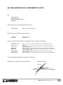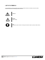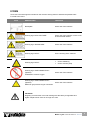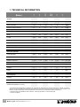
1
USER MANUAL Vacuum Packing Machine Boxer Lynx Part no 0895101 © Copyright 2014 No part of this publication may be reproduced, stored in a retrieval system, or transmitted in any form or by any electronic or mechanical means, or by photocopying, recording, or otherwise without the prior written consent of Henkelman BV. 2 USER MANUAL Boxer / Lynx Version: BL-EN-UL-0 23-03-15 INTRODUCTION Henkelman BV is a supplier of ultra-modern vacuum packing machines. Our machines are designed and manufactured to the highest standards. And that's clear. They combine a sleek built and functional design with ease of use and durability. Installation is just a matter of 'plug & pack' and the clever design ensures that the hygiene standards are maintained at all times. This manual contains relevant information and instructions for installation, operation and maintenance of the machine. The machine is not suitable for the packaging of toxic, corrosive, irritant or hazardous materials All persons responsible for the operation must at least fully read and understand the chapters on operation and safety of these operating instructions All persons responsible for assembly, installation, maintenance and/or repair should read and understand all of these instructions The user is responsible for the interpretation and use of this manual in any circumstances. Please contact the owner or the manager in case of questions or doubts about the correct interpretation This manual should be kept near the machine and should be within reach for users All major maintenance, adjustments to the machine and observations should be recorded in a log, see Appendix 10.1 Changes to the installation/machine are not permitted without prior written approval of the supplier Please contact the vendor for special servicing that is not included in this manual Comply at all times with the safety requirements, as specified in Chapter 3 The proper functioning and safety of the system can only be guaranteed if the recommended maintenance is executed on time and correctly Illustrations may differ from your machine USER MANUAL Boxer / Lynx Version: BL-EN-UL-0 23-03-15 3 TABLE OF CONTENTS LIST OF FIGURES .................................................................................................................................. 6 EC DECLARATION OF CONFORMITY (COPY) ................................................................................... 7 LIST OF SYMBOLS ................................................................................................................................ 8 ICONS ..................................................................................................................................................... 9 1. TECHNICAL INFORMATION ........................................................................................................ 10 2. DESCRIPTION OF THE MACHINE............................................................................................... 12 2.1. 2.1.1. 2.1.2. 2.2. 2.3. 2.4. 2.5. 2.6. 2.7. 2.7.1. 2.7.2. 2.7.3. 2.7.3.1. 2.7.3.2. 3. SAFETY ......................................................................................................................................... 31 3.1. 3.2. 3.3. 4. TRANSPORT AND PLACEMENT .............................................................................................. 33 CONNECTING THE MACHINE ................................................................................................. 33 START THE MACHINE FOR THE FIRST TIME ............................................................................. 33 OPERATION .................................................................................................................................. 34 5.1. 5.2. 5.3. 5.4. 5.5. 5.5.1. 5.5.1.1. 5.5.1.2. 5.5.1.3. 5.5.1.4. 5.5.1.5. 5.5.1.6. 5.5.2. 5.5.2.1. 5.5.2.2. 5.5.2.3. 5.6. 4 GENERAL ............................................................................................................................ 31 DURING NORMAL OPERATION ............................................................................................... 32 OPERATIONAL STAFF ........................................................................................................... 32 INSTALLATION ............................................................................................................................. 33 4.1. 4.2. 4.3. 5. DESCRIPTION OF THE PACKAGING PROCESS / MACHINE FUNCTIONS ....................................... 13 THE PACKAGING PROCESS / MACHINE FUNCTIONS ................................................................. 14 GENERAL FUNCTIONS.......................................................................................................... 17 THE SEAL SYSTEM ............................................................................................................... 18 THE VACUUM PUMP ............................................................................................................. 19 GAS FLUSHING (OPTIONAL) .................................................................................................. 21 ELECTRICAL INSTALLATION.................................................................................................. 21 MULTI PROGRAM DIGITAL CONTROL (MPDC) ...................................................................... 23 ADVANCED CONTROL SYSTEM (ACS) .................................................................................. 25 SETTINGS ACS GENERAL .................................................................................................... 26 IMPORT / EXPORT DATA ....................................................................................................... 28 HAZARD ANALYSIS AND CRITICAL CONTROL POINTS (HACCP) .............................................. 28 SET UP AND USE HACCP .................................................................................................... 28 EXPORT THE HACCP DATA LOG .......................................................................................... 29 STARTUP ............................................................................................................................ 34 PRODUCTION ...................................................................................................................... 34 CONTINUE TO THE NEXT STEP OF THE CYCLE ........................................................................ 35 STOP PROGRAM .................................................................................................................. 35 CHANGING THE PROGRAM SETTINGS .................................................................................... 36 MULTI PROGRAM DIGITAL CONTROL (MPDC) ...................................................................... 36 VACUUM+ OPTION (MPDC) ................................................................................................. 37 GAS+ OPTION (MPDC) ........................................................................................................ 38 LIQUID SENSOR CONTROL (MPDC) ...................................................................................... 38 RED MEAT OPTION (MPDC) ................................................................................................ 39 MULTI CYCLE OPTION (MPDC)............................................................................................. 39 EXTERNAL VACUUM OPTION (MPDC) ................................................................................... 41 ADVANCED CONTROL SYSTEM (ADC) .................................................................................. 42 PROGRAMMING THE ACS CONTROL ON YOUR PC ................................................................. 43 OPTIONS (ACS) .................................................................................................................. 44 EXTERN VACUÜM OPTIE (ACS) ............................................................................................ 45 DIRECTIVE FOR FUNCTION VALUES ....................................................................................... 46 USER MANUAL Boxer / Lynx Version: BL-EN-UL-0 23-03-15 6. MAINTENANCE ............................................................................................................................. 48 6.1. 6.2. 6.3. 6.4. 6.5. 6.6. 6.7. 6.8. M AINTENANCE DIAGRAM ...................................................................................................... 48 CLEANING THE MACHINE ...................................................................................................... 49 OIL CLEANING PROGRAM ..................................................................................................... 50 ADD OIL / CHANGE OIL ......................................................................................................... 50 REPLACING THE EXHAUST FILTER (MAINTENANCE OF VACUUM PUMP) .................................... 52 REPLACING THE SEALING WIRE ............................................................................................ 53 REPLACING THE SILICONE RUBBER ON THE SILICONE HOLDERS ............................................. 55 REPLACING THE LID GASKET ................................................................................................ 56 7. TROUBLESHOOTING ................................................................................................................... 58 8. WARRANTY CONDITIONS ........................................................................................................... 60 8.1. 8.2. 9. LIABILITY ............................................................................................................................ 60 WARRANTY ......................................................................................................................... 60 DISPOSE AS WASTE ................................................................................................................... 61 10. APPENDIX ..................................................................................................................................... 62 10.1. LOG .................................................................................................................................... 62 USER MANUAL Boxer / Lynx Version: BL-EN-UL-0 23-03-15 5 LIST OF FIGURES FIGURE 1: OVERVIEW OF THE MAIN COMPONENTS ...................................................................................... 12 FIGURE 2: OVERVIEW OF THE SEAL SYSTEM .............................................................................................. 18 FIGURE 3: OVERVIEW OF THE PUMP (FILTER COVER REMOVED) .................................................................. 20 FIGURE 4: OVERVIEW OF THE ELECTRICAL INSTALLATION ........................................................................... 22 FIGURE 5: CONTROL PANEL DIGITAL CONTROL (MPDC) ............................................................................ 23 FIGURE 6: CONTROL PANEL ADVANCED CONTROL SYSTEM (ACS) ............................................................. 25 FIGURE 7: FOUR POSSIBLE DISPLAY MODES............................................................................................... 26 FIGURE 8: OVERVIEW SETTINGS ............................................................................................................... 27 FIGURE 9: EXAMPLE OF AN EXPORTED LOG ............................................................................................... 30 FIGURE 10: CHANGING PARAMETERS (MPDC) .......................................................................................... 36 FIGURE 11: EXTERNAL VACUUM ADAPTER KIT (MPDC) .............................................................................. 41 FIGURE 12: PROGRAM DISPLAY AND CONTROLS ACS ................................................................................ 42 FIGURE 13: EXTERNAL VACUUM ADAPTER KIT (ACS) ................................................................................. 45 FIGURE 14: W ATER VAPOUR LINE ............................................................................................................. 47 FIGURE 15: MOUNTING PLATE BOXER 52 .................................................................................................. 51 FIGURE 16: REPLACING THE EXHAUST FILTER ............................................................................................ 52 FIGURE 17: REMOVING THE SEAL BAR ....................................................................................................... 53 FIGURE 18: REPLACING THE SEALING WIRE ............................................................................................... 54 FIGURE 19: REPLACING THE SILICONE RUBBER OF THE SILICONE HOLDERS ................................................. 55 FIGURE 20: REPLACING THE LID GASKET ................................................................................................... 56 6 USER MANUAL Boxer / Lynx Version: BL-EN-UL-0 23-03-15 EC DECLARATION OF CONFORMITY (COPY) We, Henkelman BV Titaniumlaan 10 5221 CK, ‘s Hertogenbosch Nederland declare under our sole responsibility that the product; Machine type: Boxer / Lynx / Toucan serie fulfils all the relevant provisions of the directives 2006/42/EG 2004/108/EG Machinery Directive EMC-Directive and is in conformity with the following standard(s) or other normative document(s); NEN-EN-ISO 12100 NEN-EN 13857 NEN-EN 349 NEN-EN 953 NEN-EN 13849-1 NEN-EN 60204-1 Safety of machinery - general principles for design – Risk assessment and risk reduction Safety of machinery – Safety distances to prevent hazard zones being reached by upper and lower limbs Safety of machinery – Minimum gaps to avoid crushing of parts of the human body Safety of machinery – Guards - General requirements for the design and construction of fixed and movable guards Safety of machinery – Safety-related parts of control systems - Part 1: General principles for design Safety of machinery – Electrical equipment of machines - Part 1: General requirements The undersigned is authorized to compile the technical file Netherlands, 's-Hertogenbosch, 28 februari 2014 Stephan Harleman Director USER MANUAL Boxer / Lynx Version: BL-EN-UL-0 23-03-15 7 LIST OF SYMBOLS For all operations in which the safety of the operator and/or technician is at stake and where caution should be exercised, the following symbols are used. Caution! Danger: High Voltage! Tip: Provides a quick overview or offers tips to make it easier to perform certain actions 8 USER MANUAL Boxer / Lynx Version: BL-EN-UL-0 23-03-15 ICONS Some icons and warnings are included on the machine among others to indicate the possible risks involved to the users. ICON DESCRIPTION LOCATION Nameplate At the rear of the machine Warning sign "HIGH VOLTAGE" At the rear of the machine, on the cover of the electrical cabinet Warning sign “SHOCK RISK” At the rear of the machine Warning sign "HEAT" On the housing of the machine Warning sign "HEAT" Warning sign “GAS CONNECTION “ (optional) On the sealbar(s) On the vacuum pump At the rear of the machine Prohibited to connect oxygen Warning sign “GAS CONNECTION “ (optional) At the rear of the machine Maximum gas pressure at gas connection CAUTION! Regularly check that the icons and markings are still clearly recognizable and legible. Replace them if this is no longer the case USER MANUAL Boxer / Lynx Version: BL-EN-UL-0 23-03-15 9 35 42 42XL 42XL BA 52 62 1. TECHNICAL INFORMATION 41 - 86 41 - 86 41 - 86 41 - 86 41 - 86 41 - 86 < 70 < 70 < 70 < 70 < 70 < 70 dB(A) 5* 5* 5* 5* 5* 5* h/day Width 17.7 19.4 19.4 15.9 27.5 27.5 inch Length 21.8 20.8 24.3 24.3 20.8 20.8 inch Height 15.9 17.3 18.5 16.5 17.3 17.3 inch Weight 108.0** 136.7** 147.7** 147.7** 145.5** 145.5** lbs 5.9 7.1 7.1 4.7 7.3 7.3 inch 0.24 0.24 0.24 0.24 0.24 0.24 inch Gas flow 60-100 60-100 60-100 60-100 60-100 60-100 l/min Maximum pressure 1 / 14.5 1 / 14.5 1 / 14.5 1 / 14.5 1 / 14.5 1 / 14.5 bar / psi Tension *** *** *** *** *** *** V Power *** *** *** *** *** *** kW Capacity 19 24 24 24 24 24 m /h Oil 0.3 0.5 0.5 0.5 0.5 0.5 liter VM32 VM32 VM32 VM32 VM32 VM32 Boxer General Ambient temperature Noise production Maximum daily production ˚F Dimensions of the machine Maximum product height Gas flush (optional) Connection size Electrical connection Vacuum pump Oil type (Ambient temperature 41-104°F) 3 * This machine is not designed for continuous use; The maximum used setting for vacuum should be 60 seconds, you have to respect a 15 seconds waiting period between each following cycle. Next to that if the machine is used for 1 hour continuous, the machine should be switched off, until the temperature of the enclosure has reached the ambient temperature ** Extensions legs are available for these machines. These legs will add 4 inch to the total height *** See the nameplate 10 USER MANUAL Boxer / Lynx Version: BL-EN-UL-0 23-03-15 32 42 Lynx 41 - 86 41 - 86 < 70 < 70 dB(A) 5* 5* h/day Width 15.7 19.3 inch Length 21.0 21.0 inch Height 15.2 15.6 inch Weight 77.2 Maximum product height 4.1 4.5 inch 0.24 0.24 inch Gas flow 60-100 60-100 l/min Maximum pressure 1 / 14.5 1 / 14.5 bar / psi General Ambient temperature Noise production Maximum daily production ˚F Dimensions of the machine 101.4** lbs Gas flush (optional) Connection size Electrical connection Tension *** *** V Power *** *** kW Capacity 9.6 19 m /h Oil 0.5 0.5 liter VM32 VM32 Vacuum pump Oil type (Ambient temperature 41-104°F) 3 * This machine is not designed for continuous use; The maximum used setting for vacuum should be 60 seconds, you have to respect a 15 seconds waiting period between each following cycle. Next to that if the machine is used for 1 hour continuous, the machine should be switched off, until the temperature of the enclosure has reached the ambient temperature ** Extensions legs are available for these machines. These legs will add 4 inch to the total height *** See the nameplate USER MANUAL Boxer / Lynx Version: BL-EN-UL-0 23-03-15 11 2. DESCRIPTION OF THE MACHINE FUNCTION This chapter provides an overview of the main components and functions If detailed information is available in this guide, you will be redirected to the specific sections The performance of your machine may differ from the figure below The figure below shows the main components of the system: 1 3 5 4 2 6 8 7 Figure 1: Overview of the main components NO. 1 PART DESCRIPTION Lid The function of the lid is to close the chamber during the vacuum cycle The lid has a lid gasket fitted, which makes sure the machine does not leak during the vacuum cycle 12 In the lid, silicone holder(s) are mounted as the opposite of the sealing bar(s) 2 Work plate / Chamber The products to be packed will be placed on the worktable / in the chamber with the opening of the vacuum seal bag on the seal position 3 Seal bar In the chamber, depending on the version, 1 or 2 seal bars are mounted. With this/these the vacuum bag is closed USER MANUAL Boxer / Lynx Version: BL-EN-UL-0 23-03-15 SECTION 6.8 2.2, 6.7 2.2, 6.6 NO. PART DESCRIPTION SECTION 4 Controlpanel See section 5 Machine housing The machine frame contains all necessary parts for the correct functioning of the machine 6 Vacuum pump See section 2.3 7 Power connection See section 2.5 8 Gas flush (optional) See section 1, 2.4 2.6, 2.7 2.1. Description of the packaging process / machine functions FUNTION This chapter provides an overview of the process and the available machine functions For the functions H2O (H2O+), Gas (Gas+) and Seal 1-2 Cut-off, specific components must be installed in your machine before they can be activated. Please contact your supplier for more details In chapter 5.5 you will find information on how to set the parameters to the correct values EXPLANATION (Only applicable to the Toucan series) The External Vacuum option does not apply On a Toucan Regular the vacuum bag is placed on the plateau in an upright position. The height of this plateau needs to be set in such a way that the seal is placed on the correct position of the vacuum bag A Toucan Square features a mold for block bags. In this mold only the specific size of the bags can be used, for which the mold is designed In a Toucan square you should first place the vacuum bag in the mold before filling it. Make sure the bag is filled sufficiently USER MANUAL Boxer / Lynx Version: BL-EN-UL-0 23-03-15 13 2.1.1. The packaging process / machine functions The following steps are taken during the process. For the detailed procedure, see Chapter 5. STEP PROCESS PHASE OPERATION 1 Preparations The operator puts the product in a vacuum bag and places it on the work top with the opening on the seal or contra bar 2 Extracting vacuum The vacuum process is started by closing the lid Depending on the options you have chosen for your machine and the product you are packaging, the following functions are available During the cycle, the air will be removed from the chamber until the set time has been reached Extracting vacuum to a set value is only possible with a sensor control (optional for Digital Control (DC). This value can be set in %. The percentage indicates the depth of the vacuum. The pressure of the outside air hereby is 0%. In the Advanced Control System (ACS), the value(s) indicated in mbar, hPa or % Available if the vacuum percentage is set to maximum Vacuum+ is an option that adds additional time to the vacuum to create the possibility to let any air escape that is still within the product FUNCTION ICON Vacuum Vacuum+ 14 Vacuum+ is only possible in combination with sensor control Gas (optional) After extracting the vacuum, a gas is injected into the chamber and the vacuum bag. This is to create a modified atmosphere to protect the shape or to increase the shelf life of the product. The value of the gas function can, depending on the control type, be set in %, mbar or hPa Gas+ (optional) Gas+ is an option that adds additional time to the gassing to increase the amount of gas in the package (see 5.5.1.2) USER MANUAL Boxer / Lynx Version: BL-EN-UL-0 23-03-15 STEP PROCESS PHASE FUNCTION OPERATION ICON Liquid Control (optional) Available with the optional Liquid Control Sensor The principle of the Liquid Control function is that it is a system that is controlled by a highly sensitive sensor. The sensor is able to detect the moment that liquids from the product or the product itself begin to vaporize (boil). At that time, the system will switch to the next step in the process. This will prevent the product from drying out, lose weight and/or splash out of the vacuum bag and thus contaminating the seal, the chamber and the oil in the pump (see 5.5.1.3) Liquid Control+ (optional) Available with the Liquid Control option The Liquid Control+ function allows you to proceed with the vacuum process for a certain time, after the evaporation phase has been reached Red Meat (optional) This function is specifically designed for packaging of fresh meat. It is added to the normal vacuum function to prevent degasification of the product during the sealing phase. This degassing can cause bubbles and causes droplet formation in the package. (see 0) Sequential vacuum (optional) Sequential vacuum makes it possible to exchange the vacuum process with pauses, so that the trapped air in a product will have the opportunity to escape. In total, up to 5 steps can be programmed. This function is available in machines with Advanced Control System (ACS) With multi-cycle it is possible to gradually extract vacuum and use gas. With this the oxygen content is reduced as well This function is available in machines with Multi Program Digital Control (MPDC) (see 5.5.1.5) Multi-cycle vacuum (optional) USER MANUAL Boxer / Lynx Version: BL-EN-UL-0 23-03-15 15 STEP 3 PROCESS PHASE OPERATION Sealing The seal bars are pressed against the contra bars, with the vacuum bag in between and melt the bag to be closed During the sealing, the material of the vacuum bag is heated and compressed to form a hermetic sealing. The function is programmed in seconds As an option, a cutting wire is available. The purpose of this wire is to remove the remaining foil from the excess flap. Depending on the chosen model, the cutting wire is controlled simultaneously, or independent from the normal seal wire (Seal 1-2 cut-off) The vacuum is released, by letting air back into the chamber This makes it possible to let air flow back into the chamber slowly, so that the vacuum bag slowly forms itself around the product. This prevents sharp edges on the product to damage the foil and possibly cause leaks FUNCTION ICON Seal 4 Releasing vacuum FUNCTION ICON Soft air (optional on Falcon) 16 5 Open vacuum chamber The lid opens 6 Remove the product The operator can remove the packed product from the worktable USER MANUAL Boxer / Lynx Version: BL-EN-UL-0 23-03-15 2.1.2. FUNCTION General Functions ICON OPERATION Cleaning the pump The pump cleaning program allows for a proper flushing of the pump. During the program, the pump and the oil will reach the operating temperature, so that the oil and the fluid will be separated and that any contamination is filtered. The high temperature takes care of evaporation of moisture in the pump, which reduces the risk of corrosion Menu This feature is available on machines with Advanced Control System (ACS) Menu is used to change the machine settings, such as language and printing options This feature is available on machines with Advanced Control System (ACS) With this function one or more labels can be created per cycle which can be stuck on the bag Print External vacuum The following information may be listed on the label: name of the manufacturer, product name, production date, shelf life, used gas, vacuum reached, the initials of the user and the recommended storage temperature This feature is available as an option depending on the machine type With this function vacuum can be applied to special food packaging gastronorm containers outside the machine The possibilities for adjusting the vacuum value are equal to the standard vacuum (see 5.5.1.6 MPDC of 5.5.2.3 ACS control) USER MANUAL Boxer / Lynx Version: BL-EN-UL-0 23-03-15 17 2.2. The seal system FUNCTION The seal system closes the opening(s) of the bag(s) to maintain the vacuum and/or gas inside The remaining flap can optionally be cut off by the seal bar 2 1 3 Figure 2: Overview of the seal system NO. 1 PART DESCRIPTION Seal bar 18 SECTION The seal bar consists of the following components Seal wires: the sealing wires are heated for a certain period of time so that the open side of the vacuum bag will melt together during the sealing Cutting wire (optional): a cutting wire is heated in such a way that the foil of the bag partially melts so that the top flap of the vacuum bag can be torn off easily Teflon-tape: sealing and cutting wires are coated with Teflon tape to prevent the bag to stick to the seal bar Refer to the indicated section for detailed information on maintenance 6.6 2 Silicon holder Opposite to each seal bar a silicone holder is mounted, which provides counter-pressure on the cylinders / seal bag 6.7 3 Seal mechanism The seal bars are pressed on the vacuum bag by using cylinders or seal bags 2.2 By connecting the outside atmospheric pressure to the inlet of the seal bags / cylinders, they will press the seal bar on the bag USER MANUAL Boxer / Lynx Version: BL-EN-UL-0 23-03-15 2.3. The vacuum pump FUNCTION The vacuum pump creates a vacuum in the chamber 8m 3 5 1 4 3 2 USER MANUAL Boxer / Lynx Version: BL-EN-UL-0 23-03-15 19 16 m 3 5 4 3 1 2 Figure 3: Overview of the pump (filter cover removed) NO. PART DESCRIPTION 1 Vacuum pump Creates the vacuum during the process 6.1 2 Exhaust filter Filters the exhaust air and absorbs oil vapors 6.1 Refer to the indicated section for detailed information with regards to maintenance The oil sight glass indicates the maximum and minimum oil level in the vacuum pump The oil sight glass is visible when te cover of the machine is in place 3 20 Oil sight glass 4 Oil drain plug In order to drain the oil 5 Oil filler plug In order to fill the pump with oil USER MANUAL Boxer / Lynx Version: BL-EN-UL-0 23-03-15 SECTION 6.1 2.4. Gas flushing (optional) FUNCTION For protection of the product it may be desirable to add a specific gas in the package after the air is removed. The machine can be provided with a gas connection optionally Installation details can be found in chapter 1 ATTENTION! 2.5. Never use a gas mixture containing over 20% of oxygen or other explosive gases. This can cause hazardous explosions By gas flushing, the seal pressure will decrease. There must be a minimum final pressure (after gas flushing) of 30% to properly seal the bag Electrical installation FUNCTION The electrical installation provides power to the vacuum pump, sealing system and control unit See the electrical diagram for the further structure and operation of the electrical installation. For the electrical diagram, please contact your dealer ATTENTION! Work on the electrical installation may only be carried out by a technical expert When performing maintenance on the machine, always unplug the power cable to avoid electrical shock The machine should always be connected to a proper grounded outlet USER MANUAL Boxer / Lynx Version: BL-EN-UL-0 23-03-15 21 3 2 1 Figure 4: Overview of the electrical installation The machine consists of the following components NO. PART DESCRIPTION 1 Power cable To connect the power supply to the machine 2 Control panel The available control functions can be used Depending on your model, your machine may have one of the following control types: 3 22 USB connection (only with ACS) Multi Program Digital Control (MPDC) 2.6 Advanced Control System?(ACS) 2.7 The USB connector is located on the side of the control box that is located behind the back panel. In order to reach the USB connection, the back panel first has to be removed The USB connector allows import and export of data USER MANUAL Boxer / Lynx Version: BL-EN-UL-0 23-03-15 SECTION/ LOCATION 2.6. Multi Program Digital Control (MPDC) FUNCTION The machine can be operated The programs can be modified See chapter 5 for instructions on operation and programming 4 6 9 1 10 2 11 3 5 7 8 Figure 5: Control panel Digital Control (MPDC) NO. ELEMENT EXPLANATION 1 Display The display shows the selected program 2 “prog 0-9” key Operate the key to select the desired program 3 “reprog” key Operate the key to switch to the program mode. The parameters can be changed by pressing the 4, 8 and 9 keys 4 Cursor key Navigates you through the functions shown in the display 6/7 5 ”Oil cleaning program” key Operate the key to activate the pump cleaning program. This removes moisture from the oil in the vacuum pump. Moisture can be absorbed by the oil when the pump is only running short cycles or when you pack products containing moisture See 0 for instructions Displays the current value of the active function during the program cycle or the set value of the selected function when the machine is idle A red dot lights up on the lower right when vacuum+ is activated The LED light for the function illuminates when the function is active during the program cycle or when the function is selected in the programming mode 6 7 Display parameter Function display USER MANUAL Boxer / Lynx Version: BL-EN-UL-0 23-03-15 23 NO. 8 9 10 11 24 ELEMENT EXPLANATION “-/stop” key The 'stop' key can be used during a packing cycle to interrupt the full cycle. All functions are cancelled, and the cycle will be terminated In the programming mode this key decreases the value of the selected parameter Stops the current function and continues with the next program step In the programming mode this key increases the value of the selected parameter Shows the pressure in the vacuum chamber A value of -1 bar corresponds to 99% vacuum This button turns the machine on/off “+/stop vacuum” key Vacuum gauge On / Off button USER MANUAL Boxer / Lynx Version: BL-EN-UL-0 23-03-15 2.7. Advanced Control System (ACS) FUNCTION The machine can be operated Programs can be changed See chapter 5 for instructions on operation and programming 2 5 1 3 4 Figure 6: Control panel Advanced Control System (ACS) NO. ELEMENT EXPLANATION 1 Stop button The 'stop' button can be used during a packing cycle to interrupt the full cycle. All functions are cancelled, and the cycle will be terminated 2 On / Off button This button turns the machine on/off 3 Display The display has four possible modes: See Figure 7 Startup mode: displays the current date and time when starting the machine. It also shows the installed software. The user cannot take action Navigation mode: shows a program with its functions. The user can navigate through the various programs and view the current setting of each function Setting mode: here the user can view and modify all settings Cycle mode: when the machine has started a packing cycle, animations of functions are displayed along with the current value of the function 4 Cursor keys With these buttons you navigate through the functions 5 Confirmation key Activates / confirms the selected value USER MANUAL Boxer / Lynx Version: BL-EN-UL-0 23-03-15 25 Figure 7: Four possible display modes 2.7.1. Settings ACS general FUNCTION To prevent unauthorized change and adjustment of settings, there are different levels of authorization. With an authorization code, you can access the different levels Users have limited access to change the settings of the machine. They can only change the printer settings using the printer icon in the navigation mode The owner of the machine is authorized to change the machine settings and all function settings An authorization code will be requested when the menu icon is selected in the navigation mode. When the code of the owner is entered, the machine setup menu opens. When logged in, the function settings can also be changed. To do this you need to go back to the navigation mode by pressing 'left' ◄ ATTENTION! 26 The machine will remember the last used authorization code, even when the machine has been turned off. Therefore, it may be necessary that you need to manually change the authorization settings when you are done USER MANUAL Boxer / Lynx Version: BL-EN-UL-0 23-03-15 With the basic functions below, you can adjust the machine and/or function settings. NO. WHAT TO DO ACTION RESULT 1 Select another setting 2 Edit selected setting Press ‘enter’ 3 Adjust the variable Use ‘up’▲ or ‘down’▼ 4 Confirm variable Press 'enter', when the desired value is found 5 Back to navigation mode When all settings are set, press ´left´◄ to return Press ‘up’▲ or ‘down’▼ Figure 8: Overview settings The site map shows all possible settings for all functions. USER MANUAL Boxer / Lynx Version: BL-EN-UL-0 23-03-15 27 2.7.2. Import / Export data FUNCTION Data such as programs and labels can be imported and exported via the USB connection Exporting HACCP data is described in 2.7.3.2 Please contact your dealer if you want to exchange other data with the controller via the USB connection . 2.7.3. Hazard analysis and critical control points (HACCP) EXPLANATION The controller is equipped with the ability to store production information. This conforms to the HACCP directives The HACCP log is stored in entries. Each entry consists of: Date, Time, User, Selected programs and settings, Selected label, Number of cycles. A new entry is saved when: Another user logs in, Program or program settings are changed, The data log is saved as a .txt file, The log data has to be exported to a USB stick (see 2.7.3.2) 2.7.3.1. Set up and use HACCP EXPLANATION Default this feature is turned off When logged in with the owners code, this feature can be enabled 5 users can be set: Owner 4 different users NO. WHAT TO DO ACTION RESULT 1 The owner logs in Log in with the owner code (1324) Access to the relevant settings 2 Turn on HACCP Go to settings<HACCP and select ON From now on, the data is logged 3 Assign initials to user codes Select the desired user code for each user Enter the initials of the user at “Name” The log file shows the initials of the user 28 USER MANUAL Boxer / Lynx Version: BL-EN-UL-0 23-03-15 ATTENTION! The initials of the users should be entered. If this is not the case, tracing the machine operator is impossible 2.7.3.2. Export the HACCP data log ATTENTION! The memory can hold up to 100 entries. If the memory is full, you will be notified The data log must then first be exported before you can continue You can export the data at any time Exporting can only be performed by the owner (owners authorization code). After exporting the data, the memory will automatically be cleared TIP Avoid unwanted delays during production by downloading the data log at scheduled times NO. WHAT TO DO ACTION RESULT 1 The owner logs in Log in with the owner code (1324) Access to the relevant settings 2 Export In the menu, go to Import/Export and select “Export” 3 Insert the USB stick Insert the USB stick in the USB connection (see electrical installation) In the display, different options appear 4 Start exporting HACCP log Select “Export HACCP” The log is transferred to the USB stick and the memory will be cleared USER MANUAL Boxer / Lynx Version: BL-EN-UL-0 23-03-15 29 1 3 4 2 5 6 User:hm started 28-3-2013 16:42 Program 2=, Vac:360.5 mbar, Seal:0.3 sec, Labelnr.:1, Amount of cycles:2 User:he started 28-3-2013 16:43 Program 1=, Sequential Vac:2.0 mbar Seal:0.4 sec, Labelnr.:1, Amount of cycles:1 User:hm started 28-3-2013 16:44 Program 3=, Vac:2.0 mbar, Seal:2.5 sec, Labelnr.:1, Amount of cycles:2 User: started 28-3-2013 16:45 Program 3=, Vac:2.0 mbar, Seal:2.5 sec, Labelnr.:1, Amount of cycles:1 Figure 9: Example of an exported log NO. 1 30 PART DESCRIPTION User initials The initials of the person who has logged in If no initials are entered in the settings, nothing is displayed here (see the bottom line of the data log) 2 Start time Start time and date of the production 3 Program The used program number 4 Vacuum The maximum vacuum reached for the package 5 Seal time The seal time used 6 Label number The label that has been printed with this package 7 Amount of cycles The total number of operating cycles from the start time USER MANUAL Boxer / Lynx Version: BL-EN-UL-0 23-03-15 7 3. SAFETY 3.1. General ATTENTION! Never pack products that can be damaged by vacuum Never pack living animals Warranty and/or liability expires if any damage is caused by repairs and/or modifications that are not authorized by the supplier or any of its distributors In case of malfunction, contact the supplier High pressure cleaning is not allowed. This can cause damage to the electronics and other components Prevent water from entering the ventilation inlet of the chamber or through the vent of the pump. This causes irreversible damage to the pump The work space around the machine must be safe. The owner of the machine must take the necessary precautions to operate the machine safely It is forbidden to start the machine in an explosive environment The machine was designed in such a way that production is safe under normal ambient conditions The owner of the machine must check that the instructions in this manual are monitored effectively The securing devices must not be removed The correct operation and safety of the system can only be guaranteed when the maintenance is performed correctly and on time, as prescribed If work on the machine must be carried out, it must be disconnected and blocked from the power supply and, if applicable, from the air and gas supply The housing of the machine may be hot after usage DANGER Only authorized persons, designated by the owner, may perform work on the electrical installation Ensure, by means of internal procedures and monitoring, that all relevant power supplies are disconnected The machine should not be used during cleaning, inspection, repair and maintenance and must be disconnected from the power supply using the plug and/or main switch Never perform welding work on the machine without disconnecting the cable connection to the electrical components first Never use the power supply of the control unit to connect to other machines All electrical connections must be connected to the terminal strip according to the wiring diagram The machine should always be connected to a proper grounded outlet USER MANUAL Boxer / Lynx Version: BL-EN-UL-0 23-03-15 31 3.2. During normal operation ATTENTION! 3.3. Before starting, ensure that no work is done on the system and that it is ready to use the machine Unauthorized persons must not operate the machine. Checking this is the task of the machine operator(s) Please immediately contact the service technician of your technical department or dealer if there are any changes, such as a poorly fitting lid, unusual vibrations or unusual noise Components of the seal system can reach high temperatures. Contact with these parts could cause injury The housing of the machine may be hot after usage Operational staff ATTENTION! 32 Operating personnel must be 18 years or older Only authorized persons will be allowed to perform work on or with the machine Only work for which one is trained should be performed. This applies to maintenance and normal use The machine may only be operated by trained personnel Operating personnel must be familiar with all situations, so that in case of an emergency quick and effective action can be taken If an operator notices errors or risks or disagrees with security, he/she should report that to the owner or manager Safety shoes are mandatory Appropriate clothing is required Everyone must follow the safety rules as one can pose a danger to themselves and others. Always follow the work instructions strictly The housing of the machine may be hot after usage USER MANUAL Boxer / Lynx Version: BL-EN-UL-0 23-03-15 4. INSTALLATION EXPLANATION Refer to chapter 1: Technical information for the correct specifications 4.1. Transport and placement ATTENTION! 4.2. The machine must be moved and transported upwards Place the machine on a flat, level surface. This is essential for trouble-free operation of the machine Machines with a plastic cover should not be placed near a heat source There must be enough space around the machine for proper ventilation. The space must be at least 15 centimeters Observe the instructions in Chapter 3 for all work to be performed. Failure to follow or ignore this may result in serious injury Make sure the machine housing is present and correctly fitted Connecting the machine ATTENTION! 4.3. Make sure that the voltage indicated on the machine plate corresponds to the mains voltage Attach the appropriate plug on the cable in accordance with local laws and connection data (see Chapter 1) Always connect the machine correctly to a grounded outlet to avoid fire or electric shock (earth is green/yellow) The power cord must always be free and nothing should be placed on it Replace the power cord immediately if damaged Connect the gas supply (if applicable). Use a quick connector or lockable shutoff valve to easily disconnect in the event of, for example, maintenance Start the machine for the first time ATTENTION! Make sure there is enough oil in the pump (Figure 3:4). If this is not the case, then fill the oil Start and use the machine (Chapter 5) USER MANUAL Boxer / Lynx Version: BL-EN-UL-0 23-03-15 33 5. OPERATION ATTENTION Observe the instructions in chapter 3 for all work to be performed Failure to follow or ignore this may result in serious injury EXPLANATION 5.1. NO. The machine is equipped with sample programs with preset parameters It is possible to optimize a program for your products by changing the parameters of the program, see Chapter 5.5 Startup WHAT TO DO ACTION RESULT 1 Turn on the power Place the plug in the socket The control is ready for use 2 Connect the additional seal pressure (if applicable) Connect the compressed air supply to the connector The additional seal pressure is ready for use 3 Connect the gas bottle (if applicable) Connect the gas supply to the connector The gas flush is ready for use 4 Switch on the control Operate the on/off button The machine is ready for use 5.2. NO. 34 Production WHAT TO DO ACTION 1 Make sure the machine is powered on See chapter 5.1 2 Select the program MPDC control: Press the program key (Figure 5:2) until the desired program appears on the display (Figure 5:1) ACS control: Use the control buttons ‘up’▲ or ‘down’▼ (Figure 6:6) USER MANUAL Boxer / Lynx Version: BL-EN-UL-0 23-03-15 RESULT NO. 3 4 5.3. WHAT TO DO st Place the 1 product Start the process ACTION RESULT Put the products in the vacuum bag Place the bag on the work table. Ensure that the opening(s) are correctly placed on the sealing position(s) On a Toucan Square first close the mold Close the lid The packing cycle starts Continue to the next step of the cycle EXPLANATION For some products, it may be necessary to proceed to the next step of the packing cycle, before the vacuum time or the vacuum level is reached NO. 1 5.4. WHAT TO DO ACTION RESULT Go to the next step of the packing cycle Press “vacuum stop” (Figure 5:9) (MPDC) The next step is started Press “right button” (►)” (Figure 6:4) (ACS) Stop program EXPLANATION Programs such as the packing program, or the oil cleaning program can be stopped at any time NO. 1 WHAT TO DO ACTION RESULT Stop the program The program will be stopped and the vacuum chamber will be decompressed Press the “stop button” (Figure 5:8) (Figure 6:1) USER MANUAL Boxer / Lynx Version: BL-EN-UL-0 23-03-15 35 5.5. Changing the program settings 5.5.1. Multi Program Digital Control (MPDC) EXPLANATION 10 programs are available. Programs 1 to 9 can be adjusted by the user. Program 0 is only intended for service purposes This section describes how parameters can be modified and indicates the units and limits of the parameters 4 6 9 1 10 2 11 3 5 7 8 Figure 10: Changing parameters (MPDC) NO. WHAT TO DO ACTION 1 Select the program to be changed Use the program ket (Figure 10:2) until the correct program number appears in the display (Figure 10:1) 2 Select the programming mode Press the “reprog” key (Figure 10:3) 3 Select the parameter Press the cursor key (Figure 10:4) to scroll thourgh the parameters The LED in the program mode display (Figure 10:7) shows at which mode you are Press “+” or “-“ (Figure 10:9/8) to adjust the values The value is saved when you press the cursor key 4 36 Change the parameter USER MANUAL Boxer / Lynx Version: BL-EN-UL-0 23-03-15 RESULT The program display flashes NO. 5 WHAT TO DO ACTION RESULT Activate the new parameter The program display stops flashing 5.5.1.1. Press the “reprog” key (Figure 10:3) Vacuum+ option (MPDC) EXPLANATION NO. If there are a lot of air inclusions in the product, it may be desirable to extend the vacuum time, after the maximum vacuum is reached. This allows more air to escape The vacuum+ time is set in seconds If a vacuum+ time is set, a dot appears in the lower right corner in the parameter display WHAT TO DO ACTION RESULT 1 Select the program on which you want to set vacuum+ 2 Select the programming mode Press the “reprog” key (Figure 10:3) 3 Select the parameter “vacuum” Press the cursor key (Figure 10:4) to scroll through the parameters The LED in the program mode display (Figure 10:7) shows at which mode you are Change the parameter vacuum to maximum (99%) Press "+" or "-" (Figure 10:9/8) to adjust the value The value is saved when you press the cursor key 5 Select the parameter vacuum+ Press the cursor key once The display shows “OFF:”. The LED in the function display will remain on vacuum 6 Change the parameter vacuum+ (seconds) Press “+” of “-“ (Figure 10:9/8) to adjust the value The value is saved when you press the cursor key When setting a value a dot appears in the lower right corner in the parameter display Activate the new parameter Press the “reprog” key (Figure 10:3) 4 7 Use the program key (Figure 10:2) until the correct program number appears in the display (Figure 10:1) The program display flashes The display shows “99” The program display stops flashing USER MANUAL Boxer / Lynx Version: BL-EN-UL-0 23-03-15 37 5.5.1.2. Gas+ option (MPDC) EXPLANATION 5.5.1.3. This option is only applicable if the machine is equipped with the gas option With the Gas+ option, it is possible to provide the maximum amount of gas to a package. This allows to create a 'balloon-package' If Gas + is set, a dot will appear in the lower right corner in the program display If Gas+ is set, it applies to all programs where gas is set To set this function, you should contact your supplier Liquid sensor control (MPDC) EXPLANATION When the liquid sensor control is set, the machine will remove air, to the maximum vacuum (99%). If the product reaches the boiling point before reaching the maximum vacuum, the machine will continue to the next step of the cycle For each program, the liquid sensor control option can be switched on or off NO. 38 WHAT TO DO ACTION RESULT 1 Select the program on which you want to set liquid control 2 Select the programming mode Press the “reprog” key (Figure 10:3) The program display flashes 3 Select the liquid control option Press the program key (Figure 10:2) until H2O appears in the display (Figure 10:1) H2O appears in the parameter display 4 Activate the new parameter Press the “reprog” key (Figure 10:3) The program display stops flashing USER MANUAL Boxer / Lynx Version: BL-EN-UL-0 23-03-15 Use the program button (Figure 10:2) until the correct program number appears in the display (Figure 10:1) 5.5.1.4. Red Meat option (MPDC) EXPLANATION 5.5.1.5. This function is especially designed for packing fresh meat By degassing of the product during the process, bubble and droplet formation can occur inside the package. Degassing of the product during the sealing phase is prevented with this option This option can be set for each program separately If the Red Meat option is activated in a program, the soft-air feature is no longer available To set this option, you should contact your supplier With this option, a parameter appears to set the expansion reduction time. This is indicated by the flashing soft-air LED in the function display. It is recommended not to change this setting. Please contact your supplier for this Multi cycle option (MPDC) EXPLANATION With multi-cycle the vacuum and gas flush process can be programmed in a maximum of 5 steps With this the oxygen content will be reduced additionally This function is only useful in very specific applications where very special requirements are set for the residual oxygen content. In the food industry, this option will cause no significant advantage To activate this option, contact your supplier USER MANUAL Boxer / Lynx Version: BL-EN-UL-0 23-03-15 39 Programming the multi cycle steps NO. ACTION RESULT 1 Select the program on which you want to set the multi cycle 2 Select the programming modus Press the “reprog” key (Figure 10:3) The program display flashes 3 Select the parameter vacuum Press the cursor key (Figure 10:4) to scroll through the parameters The LED in the program mode display (Figure 10:7) shows at which mode you are The right character of the parameter display shows that vacuum step you are programming (see Figure 10:5) Press "+" or "-" (Figure 10:9/8) to adjust the value The value is saved when you press the cursor key Press the cursor key (Figure 10:4) to scroll through the parameters The LED in the program mode display (Figure 10:7) shows at which mode you are Press "+" or "-" (Figure 10:9/8) to adjust the value The value is saved when you press the cursor key Press the "reprog" key (Figure 10:3) 4 5 6 40 WHAT TO DO Change the parameter vacuum Select the parameter gas Change the parameter gas 7 If an additional vacuum step is required go to number 3 8 Activate the new parameter USER MANUAL Boxer / Lynx Version: BL-EN-UL-0 23-03-15 Use the program key (Figure 10:2) until the correct program number appears in the display (Figure 10:1) The program display stops flashing 5.5.1.6. External vacuum option (MPDC) EXPLANATION With this function vacuum can be applied to special food packaging gastronorm containers outside the machine Depending on whether the machine has time or sensor control features, the vacuum value is set in seconds or % First check whether the container is resistant to a vacuum and can retain this 2 1 3 Figure 11: External vacuum adapter kit (MPDC) NO. 1 WHAT TO DO ACTION RESULT Select the external vacuum program Press the oil cleaning program key (Figure 10:5) “C” appears in the display Press the cursor key (Figure 10:4) “E” appears in the display The external vacuum program can be programmed in the same way as any other program (see section 5.5.1) 2 Connect the external vacuum hose to the machine Place the adapter over the suction hole in the vacuum chamber (Figure 11:1) 3 Connect the external vacuum hose to the container Connect the vacuum hose adapter (Figure 11:3) on the valve of the container. And slide the valve (Figure 11:2) in the direction of the hose (closed position) 4 Start the process Press the “+” key Vacuum will be applied until the programmed value is reached 5 Disconnect the external vacuum hose from the container Slide the valve of the adapter in the direction of the package (open position) and remove the hose Hose will be disconnected from the container and can be removed USER MANUAL Boxer / Lynx Version: BL-EN-UL-0 23-03-15 41 5.5.2. Advanced Control System (ADC) EXPLANATION sers can see the machine programs and access the functions in the navigation mode. This is the mode that appears immediately after boot time. Figure 12 shows a screenshot of this mode NO. ELEMENT EXPLANATION 1 Program number / name The program shows the currently selected, preset program. By switching to a different program, different functions will be active. The program choice depends on the product that will be packed 2 View the functions These features are active or inactive. If a function is activated, it will be displayed with a blue tint. When a function is not active, it will be displayed in a soft gray tint 3 Function active/inactive The selected function is marked with a green circle. The name and current value of this function is displayed on the screen If the Plus functions are activated, the + illustration will be shown in color. If these are not active, they are displayed in a soft gray tint The machine settings can be adjusted via the menu icon on the left of the function list 4 Menu 1 2 4 3 Figure 12: Program Display and controls ACS 42 USER MANUAL Boxer / Lynx Version: BL-EN-UL-0 23-03-15 NO. WHAT TO DO ACTION RESULT 1 Select the desired program Use the control buttons ‘up’ ▲ or ‘down’ ▼ 2 View the functions Use the control buttons ‘left’◄ or ‘right’► 3 View/edit function settings Press 'enter' when the function is selected. Users can view the preset configuration and the owner can also edit. (see section 2.7) 4 Editing machine settings Press 'enter' when the menu is selected (only accessible to the owner) (see section 2.7, 5.6) 5.5.2.1. Programming the ACS control on your PC Import files You can import labels and programs from a USB stick, by plugging it into the USB port of the machine. The imported data can be created using the online software for programming. You will find this software on our website on the 'Support' page: http://www.henkelman.com/en/support/downloads Or contact your supplier. Creating a program or label and import them into the machine: Click on the link of the LX Software, the following page will open: Start a new program by: Select a program or label you want to change You can also import existing programs and/or labels that you like to change in: Select a file to import Then select a program or a label and click on the 'GO' button USER MANUAL Boxer / Lynx Version: BL-EN-UL-0 23-03-15 43 Complete all data you want to use. Click 'Save' to save the program or the label. It is necessary to validate each label or program separately after changing the settings. When you have finished programming all programs and labels, you can save them by choosing a file on your computer and click ´Export´. When you select 'Programs', all programs will be saved. By selecting ´Labels´ all labels will be saved. For the transmission on your machine, be sure to use an empty USB key to export files. To import the settings in the machine, plug the stick in the USB port of the machine, go to import / export in the menu and import the programmes and labels. 5.5.2.2. Options (ACS) EXPLANATION 44 The options that are built into the machine can be enabled or disabled at the settings menu by the owner (login as owner) (See section 2.7.1) Subsequently the options in the various programs can be programmed USER MANUAL Boxer / Lynx Version: BL-EN-UL-0 23-03-15 5.5.2.3. Extern Vacuüm optie (ACS) TOELICHTING With this function vacuum can be applied to special food packaging gastronorm containers outside the machine Vacuum will be applied to 99% First check whether the container is resistant to a vacuum and can retain this 1 2 3 Figure 13: External vacuum adapter kit (ACS) NO. WHAT TO DO ACTION RESULT 1 Connect the external vacuum hose to the machine Place the adapter over the suction hole in the vacuum chamber (Figure 13:1) 2 Connect the external vacuum hose to the container Connect the vacuum hose adapter (Figure 13:3) on the valve of the container. And slide the valve (Figure 13:2) in the direction of the hose (closed position) 3 Start the process With the controls, select the external vacuum program Vacuum is applied to the maximum level 4 Disconnect the external vacuum hose from the container Slide the valve of the adapter in the direction of the package (open position) and remove the hose Hose will be disconnected from the container and can be removed USER MANUAL Boxer / Lynx Version: BL-EN-UL-0 23-03-15 45 5.6. Directive for function values EXPLANATION For each function, values can be set if you are authorized as the owner. In order to understand the impact of the set value the table below explains the consequences of giving a low or high value for each function FUNCTION RANGE Vacuum 2-700 mbar 30-99.8% Rule of thumb: the higher the vacuum, the less oxygen remains in the package, so the product has a longer shelf life. There are exceptions to this rule Vacuum+ 0-20 sec This is the time that vacuum continues after the maximum vacuum is reached. This is to let the entrapped air escape from the product. Note: Vacuum should be set to the maximum Red Meat 2-700 mbar Rule of thumb: the higher the vacuum, the less oxygen in the package so that the product has a longer shelf life 30-99.8% Liquid Control 2-700 mbar When the pressure decreases, the boiling point of water is reduced. This physical law can cause the product to boil. In addition to contamination of the machine, this provides loss of weight and quality of the product to be packed. By enabling the Liquid Control feature this special sensor will detect the evaporation point and ensures that the program will continue with the next step in the packing process. The value to set is the maximum achievable vacuum level. Please note that this vacuum value is only feasible as long as the product does not boil Liquid Control+ 0,1-5,0 sec This is the time that vacuum continues after detection of the evaporation point. Due to the evaporation, a small shock wave may occur that will press all the remaining air out of the bag. The best way to determine the right time is by trial and error to determine the optimal value Sequential vacuum 2-700 mbar When the value for vacuum+ time is not effective enough to let the trapped air escape, the sequential vacuum function must be turned on. In a maximum of five steps vacuum will be alternated with a hold period. Each step provides a higher vacuum than the preceding step 30-99,8% Seal time 0,1-4,0 sec 1-2 cutting time 46 CONDITIONS USER MANUAL Boxer / Lynx Version: BL-EN-UL-0 23-03-15 This is the time in which the seal wire and/or cutting wire is heated. The longer the time, the more heat is being transferred to the bag FUNCTION RANGE CONDITIONS Soft-air 1-20 sec The length of time in which air is introduced to the chamber after sealing. The best way to determine the correct time is by trial and learn by mistakes Cleaning of the pump 15 minuten There are no settings possible ATTENTION! The vacuum pressure in the chamber should be at least 30% at the time of sealing EXPLANATION When the pressure decreases, the boiling point of water is reduced (see Figure 14). This physical law can cause a product to boil. In addition to contamination of the machine, this provides for loss of weight and quality of the product to be packed When packing products that contain moisture such as soups and sauces, it is important to follow the vacuum process closely. At the moment that bubbles are formed or it starts to bubble, immediately proceed to the next step in the cycle (see section 5.3) By cooling the products as much as possible, before applying vacuum, a deeper vacuum can be achieved If a machine is equipped with a liquid sensor option, the control automatically goes to the next step when boiling occurs When packaging moisture containing products, it is important that the conditioning program is run at least 1 time per week. With daily vacuuming of moisture containing products, it is recommended to run the conditioning program at the end of the day Figure 14: Water vapour line USER MANUAL Boxer / Lynx Version: BL-EN-UL-0 23-03-15 47 6. MAINTENANCE ATTENTION! Always disconnect the power supply by unplugging the power cord Always disconnect the external pressure (if applicable) Test the machine after maintenance or repairs, so it is certain that the machine can be safely used Only trained personnel should perform the described maintenance work 6.1. Maintenance diagram Every 4 years Yearly Every 6 months LUBRICANT Weekly ACTIVITY Daily The diagram below shows the maintenance activities that must be performed. SECTION Cleaning Cleaning the machine 6.2 Lubrication Replace the oil of the vacuum pump See chapter 1 for oil type 1 Inspections Check the oil level 2.3 Execute the oil cleaning program 6.3 Inspect the seal bars 6.6 Inspect the silicone rubber of the silicone holders 6.7 Inspect the lid seal 6.8 Check the plastic lid for cracks 48 USER MANUAL Boxer / Lynx Version: BL-EN-UL-0 23-03-15 Every 4 years Yearly Every 6 months LUBRICANT Weekly Daily ACTIVITY SECTION Replacements Replace the sealing wires 6.6 Replace the silicone rubber of the silicone holders 6.7 Replace the lid seal 6.8 Replace the exhaust filter 6.5 Please contact your supplier for a professional service Replace the plastic lid 6.2. Cleaning the machine EXPLANATION NO. 1 It is not allowed to clean with a high pressure cleaning machine Do not use harsh or toxic cleaning materials Do not use cleaning materials with solvents WHAT TO DO ACTION Clean the machine RESULT You can clean the surfaces with a soft, damp cloth, or you can apply your cleaner to the machine and wipe it off with clean water USER MANUAL Boxer / Lynx Version: BL-EN-UL-0 23-03-15 49 6.3. Oil cleaning program EXPLANATION NO. 1 2 The oil cleaning program will let the vacuum pump run for 15 minutes. During the program, the pump and the oil will reach the operating temperature. The oil absorbs fluid in the pump. The high temperature ensures that the moisture evaporates in the pump and reduces the risk of corrosion If you pack moist products, such as soups or sauces, it is necessary to use the oil cleaning program more often than the prescribed interval of once a week WHAT TO DO ACTION Select the program MPDC: Press the key for the oil cleaning program (Figure 5:5) ACS: Use the control buttons "up" ▲ and "down" ▼ (Figure 6:4) Close the lid Start process RESULT The oil cleaning program will be executed for 15 minutes 6.4. Add oil / change oil WARNING The oil in the vacuum pump can be hot. When replacing the oil contact with hot oil may be possible EXPLANATION If the machine will not be used for long periods of time, the oil should be removed from the pump. This is because any moisture and dirt in the oil can affect the pump, causing the pump to jam at the next use 50 USER MANUAL Boxer / Lynx Version: BL-EN-UL-0 23-03-15 Add oil NO. 1 WHAT TO DO ACTION RESULT Add oil Remove the oil filler plug (Figure 3:5) Add oil until the oil level is between the "max" and "min" level (Figure 3:3) Place back the oil filler plug Replacing oil 1 2 3 Figure 15: Mounting plate Boxer 52 NO. 1 2 WHAT TO DO ACTION Place the drain plug outside the housing (only Boxer 52) Remove the bolts (Figure 15:1) from the mounting plate (Figure 15:3) and take them away Turn the mountingplate out, so a drip pan can be placed underneath the drain plug (Figure 15:2) Place a drip pan under the oil drain plug (Figure 3:4) Remove the oil drain plug (Figure 3:4) Place back the oil drain plug Change oil RESULT The oil drains from the pump USER MANUAL Boxer / Lynx Version: BL-EN-UL-0 23-03-15 51 NR. WAT TE DOEN ACTIE 3 Fill with new oil Remove the oil filler plug (Figure 3:5) Add oil until the oil level is between the "max" and "min" level (Figure 3:3) Place back the oil filler plug Turn the mounting plate with the vacum pump back into the housing Place back the bolts (Figure 15:1) in the mounting plate (Figure 15:3) and tighten them 4 Place back the vacuum pump in the housing (only Boxer 52) RESULTAAT 6.5. Replacing the exhaust filter (maintenance of vacuum pump) EXPLANATION 1. The exhaust filter prevents oil vapors to be emitted by the exhaust air from the vacuum pump 2. If the filter becomes saturated, it is no longer possible to reach maximum vacuum 3. Replace the filter in case of vacuum problems, or in accordance with the maintenance diagram of Chapter 6.1 3 16 m pump 1 Figure 16: Replacing the exhaust filter 52 USER MANUAL Boxer / Lynx Version: BL-EN-UL-0 23-03-15 2 3 4 NO. 1 2 WHAT TO DO ACTION Remove the exhaust filter Remove the filter cover (Figure 16: 4) from the vacuum pump (Figure 16: 1) Remove the leaf spring (Figure 16: 3) Remove the old filter (Figure 16: 2) Place the new filter in the opening Make sure the O-ring is properly placed on the filter inlet Install the leaf spring Install the filter cover Install the new filter RESULT 6.6. Replacing the sealing wire EXPLANATION Depending on your machine specification you can have one of the following (combinations of) seal elements: • Double seal: Two sealing wires • Cut-off seal: One sealing wire and one cutting wire • Wide sealing: One wide sealing wire • Bi-active seal: One seal bar with wide sealing wire on both sides The process of replacing of the seal elements is the same for all types Make sure, for bi-active seal systems, that the upper and lower seal elements are precisely aligned during the sealing Replace the sealing wires if the wire and/or the Teflon tape is damaged, or in accordance with the maintenance diagram 1 Figure 17: Removing the seal bar USER MANUAL Boxer / Lynx Version: BL-EN-UL-0 23-03-15 53 1 2 4 3 5 6 Figure 18: Replacing the sealing wire NO. WHAT TO DO ACTION 1 Remove the seal bar from his holders Lift the sealing bar (Figure 17:1) from the cylinders 2 Remove the teflon tape Remove the teflon tape (Figure 18:1) that protects the sealing wires 3 Remove the old sealing wires Remove the screws (Figure 18:2) on the bottom side of the seal bar, and remove the sealing wires (Figure 18:3) 4 Replace the teflon tape on the sealing bar Pull the teflon tape from the top of the sealing bar (Figure 18:4) Clean the bar with a lint-free cloth Put a new piece of Teflon tape of the same length on the sealing bar Cut a new piece of sealing wire or cutting wire at the length of the seal bar plus about 15 cm (6 inches) First place the wire on one side of the seal bar by tightening the screws (Figure 18:2) Place the other end of the wire in a straight line and tighten with pliers. Then fasten it by tightening the screws Trim the ends of the wire on both sides 5 54 Replace the sealing wires USER MANUAL Boxer / Lynx Version: BL-EN-UL-0 23-03-15 RESULT NO. 6 7 WHAT TO DO ACTION RESULT Replace the teflon tape on the sealing wire Cut a piece of teflon tape at the length of the seal bar plus about 5 cm (2 inches) Stick the tape smoothly and without folds over the sealing wires on the sealing bar Place seal bar Place back the seal bar 6.7. Replacing the silicone rubber on the silicone holders EXPLANATION In order to obtain a seal of good quality, the rubber should not be damaged and the surface must be flat Damage may be caused by burning with the seal wire or mechanical contact Replace the silicone rubber if it is damaged, or in accordance with the maintenance diagram in chapter 6.1 1 Figure 19: Replacing the silicone rubber of the silicone holders USER MANUAL Boxer / Lynx Version: BL-EN-UL-0 23-03-15 55 NO. WHAT TO DO ACTION 1 Remove the old silicone rubber You can pull the old silicone rubber (Figure 19:1) from the holder 2 Cut the new silicone rubber Cut a new piece of rubber. Make sure that it is just as long as the holder The size is very important, it will cause problems with the seal of the bag if the rubber is too short or too long 3 RESULT Place the new silicone rubber Place the new piece in the silicone holder by pushing it into the recess Ensure that the silicone rubber is fully and uniformly placed in the slot. It is also important that the surface of the silicone rubber is smooth after it is in place and that it shows no signs of stress 6.8. Replacing the lid gasket EXPLANATION The lid gasket ensures that the vacuum chamber is completely closed off during the machine cycle. This is essential for the achievement of a maximum vacuum level. The lid gasket will wear out due to extreme pressure differences and should be changed regularly Replace the lid gasket if it is damaged or in accordance with the maintenance schedule in section 6.1 1 Figure 20: Replacing the lid gasket 56 USER MANUAL Boxer / Lynx Version: BL-EN-UL-0 23-03-15 NO. WHAT TO DO ACTION 1 Remove the old gasket You can pull the old lid gasket off 2 Cut a new piece of gasket Cut a new piece of gasket. Cut it preferably slightly longer than the old one The ends must be cut off straight When the lid gasket is too short or too long, it can cause problems when closing the cover or leakage may occur Place the new lid gasket by pressing it in the slot. The lip of the gasket must face downwards and outwards The gasket should be placed in the holder evenly and without tension. The ends must come tightly together to prevent leakage 3 Place the new rubber RESULT USER MANUAL Boxer / Lynx Version: BL-EN-UL-0 23-03-15 57 7. TROUBLESHOOTING The tables below show the possible interference with the corresponding cause and action to be taken MALFUNCTION ACTIVITY Control panel does not illuminate Connect the machine to the power supply 2.5 The control panel is on but there is no activity after closing the lid Check / adjust the micro switch of the lid Please contact your supplier Insufficient final vacuum Check the vacuum settings of the program and adjust them Make sure that the extraction opening is not covered Check the oil level in the pump 2.3 Check / replace the exhaust filter 6.5 Check / replace the lid gasket 6.8 Make sure that the extraction opening is not covered Check the oil level in the pump 2.3 Check/ replace the exhaust filter 6.5 Check the seal program settings and adjust them 5.5 Check / replace the Teflon tape and sealing wires 6.6 Check / replace silicones in the silicon holders 6.7 Check the inside of the vacuum for contamination and clean it Check the gas springs Vacuum process is slow Vacuum bag is not sealed correctly The lid does not open automatically 58 USER MANUAL Boxer / Lynx Version: BL-EN-UL-0 23-03-15 SECTION 5.5 Please contact your supplier Error messages for MPDC F1 in display F2 in display Check / adjust the micro switch of the lid Make sure that the pump is running correctly Check if the cover is opened and restart the machine When message is repeated: Check if the lid is opened correctly (MPDC with sensor control) --- in display Please contact your supplier Please contact your supplier USER MANUAL Boxer / Lynx Version: BL-EN-UL-0 23-03-15 59 8. WARRANTY CONDITIONS This manual has been compiled with care. However Henkelman BV accepts no liability for any errors in this manual and/or for the consequences of an erroneous interpretation of the instructions. Henkelman BV accepts no liability for damage and/or problems arising from the use of spare parts not supplied by Henkelman BV. Henkelman BV reserves the right to change specifications and/or spare parts without prior notice. 8.1. Liability 1. We disclaim any liability to the extent that it is not required by law. 2. Our liability is limited to the total monetary amount of the value of the related machine. 3. With the exception of the applicable statutory provisions on public policy and good faith we are not obliged to pay to the counterparty or to third parties, any damages of any nature whatsoever, direct or indirect, including loss of profit, damage to movable or other property or personal injury. 4. We are in no way responsible for damages resulting from or caused by the use of the product used, or the unsuitability thereof for the purpose for which the other party decided to purchase. 8.2. Warranty The warranty is subject to the following limitations. The warranty period for products supplied by Henkelman is 3 years from the date of the purchase document. This warranty is limited to manufacturing and machine errors, and therefore does not cover malfunctions due to a component of the product that has been exposed to any type of wear. Normal wear and tear as expected with the use of this product is therefore hereby excluded.. 1. The responsibility of Henkelman is limited to the replacement of defective parts, we recognize no claims for any other form of damages or costs. 2. The warranty expires automatically in case of arrears or poor maintenance. 3. If there are doubts about maintenance or if the machine is not working properly, contact should always be made with the supplier. 4. The warranty does not apply if the defect is the result of improper or negligent use, or maintenance that is carried out in breach of the instructions mentioned in this manual. 5. The warranty is void if repairs or modifications on the product are carried out by third parties. 6. Defects arising from damage or injury caused by external factors are excluded from the warranty. 7. If we replace parts in accordance with the requirements of this warranty, the replaced components become our property. The provisions relating to warranty and liability are part of the general terms that can be sent on request. 60 USER MANUAL Boxer / Lynx Version: BL-EN-UL-0 23-03-15 9. DISPOSE AS WASTE Do not dispose oil and components with the household waste. Ensure that at the replacement of parts or oil after the lifecycle, that all materials are collected and destroyed or recycled in a legal and environmentally friendly manner. USER MANUAL Boxer / Lynx Version: BL-EN-UL-0 23-03-15 61 10. APPENDIX 10.1. Log This log should include among other things: ● Annual maintenance ● Big replacements and emergencies ● Modifications ● Tests of the emergency stop buttons and safety devices DATE: 62 EXECUTED BY: DESCRIPTION: (AUTORITY, TECHNICIAN) (NATURE OF THE ACTIVITIES, WHAT IS REPLACED) USER MANUAL Boxer / Lynx Version: BL-EN-UL-0 23-03-15 USER MANUAL Boxer / Lynx Version: BL-EN-UL-0 23-03-15 63 Henkelman BV Titaniumlaan 10 5221 CK, ‘s Hertogenbosch The Netherlands : +31-(0)73 621 3671 : +31-(0)73-622 1318 Email: [email protected] Website: www.henkelman.com 64 USER MANUAL Boxer / Lynx Version: BL-EN-UL-0 23-03-15