1
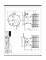
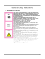
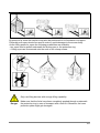
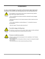
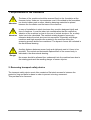
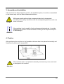
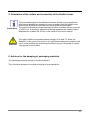
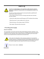
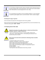
Instruction Manual
for
Tumbler Screening Machine
VTU
Product Description
1. Defined Use
The Tumbler Screening Machine VTU should only be
used for the screening of bulk material and dry products.
If the machine is not used according to this definition, the
operation of the unit may not be safe.
Danger
All injuries to persons or damages to the material occurring due to
such undefined use will be declined and are the sole responsibility
of the user!
The machine should never be used for any other than the indicated purpose. It is
especially forbidden to use the Tumbler Screening Machine as a mixer or a blender or a
dryer.
We decline all responsibility with regard to any law of product responsibility for any
kind of damages and consecutive damages which may occur due to an incorrect
installation or use of the machines supplied by us.
2
2. Assembly
The Tumbler Screening Machine VTU assembly consist of:
- A machine base with main shaft, V-belt drive and electric motor, to be fixed on the
floor.
- An adjustment system in order to achieve the three dimensional movement.
- A vibrating bottom pan with main pivot in the centre and product outlet for fines
- One or more intermediate rings with product outlets
- One or more pre-tensioned screen inserts with mesh cloth
- One or more anti-blinding systems such as balls
- A top cover with inlet and product oversize outlet.
Tumbler Screening Machines VTU are being manufactured in stainless steel.
Stainless steel surfaces may be polished smooth inside and outside or blasted with glass
beads.
By use of special profiles which are used for the pan, intermediate rings and the cover a
perfect alignment and self-centring of the screens and screen body will be achieved.
3
3. Description of operation
Basically the movement of a Tumbler Screening Machine VTU can be compared to
natural hand screening.
If no data or information is available about the product to be screened, it is recommended
to run first trials in the test centre. The results of these tests are the basis for the later
optimum use of the screening machine.
The product is continuously fed to the centre of the machine from where it spreads
uniformly to the outside over the entire screening surface. The finer particles are passing
through the screen near the centre and the coarser ones are passing through at the
periphery. The material is moved in a spiral way over the screen with increasing
acceleration to the outside where the narrow-sized particles will also pass through the
mesh. The oversize is normally directed by a deflector - like a simple door - into the outlet.
Additionally to the set movement the adjusted deflector opening increases or decreases
the retention time of the product on the screen. On each deck the screening process will
be repeated.
The heart of the Tumbler Screening Machine is the patented adjustment system for the
individual retention time of each product to be screened.
Between main shaft and main pivot first an eccentric displacement will be adjusted
between 20-40 mm. A basic plane rotating movement of the screen body is created.
The speed is set between 170-270 rpm. The screen body is inclined radially as well as
tangentially towards the drive axis, thus creating the three-dimensional movement.
The movement of the machine can be recorded with a special axially mobile pen on a
master chart where the movements can be measured exactly. The data can always be
transmitted by phone or fax or email for further checking. Optimum settings will be always
available and reproducible.
The primary necessity for a continuous operation is clean and unclogged or not blinded
screen meshes. Otherwise, the capacity and the efficiency of the machine will be reduced.
The modular design of the Tumbler Screening Machine enables the installation of very
effective anti-blinding systems depending on the products to be screened.
4. Technical Data
See attached dimensional drawing.
4
5
General safety instructions
1. RESPONSIBILITY OF THE USER
Labour
Safety
Regulations
For
Accident
Prevention
Manual
The Tumbler Screening Machine VTU has been designed and
manufactured by observing a hazard analysis and choice of the
harmonized norms, as well as further technical specifications.
It corresponds to today’s technical practice and assures maximum
safety during operation.
The safety of the machine during operation can only be
guaranteed with all the necessary requirements taken. It is the
responsibility of the user of the machine to plan these
requirements and to control their execution.
The user must especially make sure, that
• the machine is only used according to its defined use, (see
Product Description No.1)
• the machine is only operated in perfect, operational condition
and that the safety devices are checked regularly for their
proper function.
• the required personal safety devices for the operators,
maintenance staff and other persons are available and being
used.
• this manual is always available next to the machine in a well
readable condition.
• only qualified and authorized staff will operate, maintain or
repair the machine.
• the operating staff will be regularly instructed in questions of
operational safety and environmental protection; additionally
they have to be familiar with the instruction manual and the
safety instructions mentioned therein.
• all the safety and warning symbols fixed by the manufacturer
on the machine are in place and in well-readable condition.
• the manual should be completed with national or
companyspecific
regulations to prevent any accidents.
6
2. EXPLANATION OF THE USED SAFETY SYMBOLS AND PRECISE SAFETY ADVICES
Precise safety advices are given in the following paragraphs to inform about the residual
risk during the operation and use of the machine. This risk could endanger:
· persons
· the product and the machine
· the environment
The symbols used in this manual shall alert the reader to the safety advices!
This symbol alerts when there is danger especially for
persons.
(danger of death, danger of injuries)
Danger
This symbol alerts when there is danger for the machine, the
material and the environment.
Attention
The most important aim of these safety instructions is to prevent damages to the
machine and injuries to persons.
· If the symbol DANGER is shown in an advice there might also be dangers for the
machine, material and environment to be expected.
· If the symbol ATTENTION is shown in an advice there will be no danger to persons
to be expected
The symbol used for any advice is not meant to replace the written text which should
always be read completely!
This symbol does not refer to safety advices, but gives
information for a better understanding and implies a more
economic use of the machine.
Information
7
3. Primary safety requirements in normal operation
The machine must only be operated by skilled and authorized
staff, knowing the manual and able to work according to it!
Before starting the machine you must check and assure that:
- only authorized staff are within the working area of the
machine!
- nobody can be injured, when the machine starts!
- nobody is touching the machine or moving parts of it during
operation because of the danger of injuries!
Check the machine before each start for visible damages and
make sure that it will only be operated in a perfect condition!
The supervisor must be informed immediately about obvious
damages!
Remove all materials, pieces and parts which are not necessary
for the production from the working area of the machine before
starting it!
Check and make sure before each start that all safety devices are
in perfect condition!
4. Basic safety requirements for maintenance
The inspection and maintenance intervals given in the manual
must be strictly adhered to!
The information for maintenance and repairs of the single
components must be observed!
Block the access for not authorized staff to the working area of the
machine prior to starting any maintenance and repair jobs!
Put up a sign showing that maintenance and repair works are
going on!
8
Shut off the electric mains switch and secure it by means of a lock
prior to starting any maintenance and repair job!
The key for the lock must be in the possession of the person
doing the maintenance or repair work!
Only use lifting devices that are in perfect condition in case of
changing heavy machine parts!
Make sure that all the parts which will be touched later have
cooled down to ambient temperature!
All greasing, cooling or cleaning materials must be disposed of
according to the environmental safety regulations in your country!
Used Oils
Works on the electric equipment
Repair works on the electric equipment of the machine must only
be performed by authorised and skilled electricians!
Check the electric equipment regularly!
Re-fix loose connections!
Exchange damaged cables immediately!
Always close the control panel! Permit access only for authorised
staff with key and tools.
Never splash water for cleaning onto the control panels and any
other electric housing!
9
Works on hydraulic and pneumatic equipment
Maintenance and repair work on hydraulic or pneumatic
equipment should only be performed by especially skilled staff!
Prior to starting any maintenance and repair work make sure
that the hydraulic or pneumatic system is pressure less!
Exchange hoses and pipes in preventative maintenance
regularly, even if there are no visible damages. (Manufacturer’s
instructions are to be observed!)
Before any start-up after maintenance or repair works check all
threaded connections for fixed seats.
- that all covers, screens and filters have been put back and
closed.
After having finished the maintenance or repair job and before
restarting the production make sure that:
- all the tools, parts and pieces which have been used during
maintenance and repair have been removed from the working
area of the machine!
- all liquids which might have dripped out have been removed!
- all safety devices of the system are in perfect condition!
5. Environmental protection
The environmental regulations - as put down in the environmental
legislation of your country - have to be observed during all the
work on and with the machine.
Especially during installation, repair and maintenance jobs no
water hazardous materials such as
- grease and oils
- hydraulic oils
- cooling agents
- solvents and cleaning liquids
may spoil the soil or reach the sewage water system. Instead, the
materials must be stored, transported, recovered and disposed of
in adequate containers.
10
6. Requirements to the Operators
The user must assure especially that
- only qualified and authorised staff are operating, maintaining or repairing the machine
- the staff will be instructed regularly with regard to questions of operational safety and
environmental protection; they also have to be familiar with this instruction manual and
the safety instructions mentioned therein.
7. Special kinds of danger
The machine has dangerous, moving, rotating and electric parts. They may cause very
severe injuries to the personnel or damages to the material, if the safety protections are
removed without authorisation or if the safety or maintenance instructions are not obeyed.
No modifications, add-ons or changes to the machine are allowed, which could reduce its
safety, without talking to the manufacturer first and without his explicit approval.
Spare parts must correspond to the technical requirements specified by the manufacturer.
This is only guaranteed by using ORIGINAL spare parts.
11
Transport
The Tumbler Screening Machine VTU will always be shipped completely assembled,
ready to be connected and to operate and - in most cases - on a transport pallet.
The machine has been secured against turning movements by means of a transport
safety device.
The following points must be obeyed in order to avoid machine damages or
life hazardous injuries during the transport of the machine:
Danger
- The transportation should only be performed by qualified staff observing
the safety instructions.
- The machine should only be moved or lifted on the lifting points indicated.
- Only the lifting devices indicated hereafter should be used for transport.
- See the chapter “General safety instructions”
1. Dimensions and weight
The dimensions and weight of the machine can be seen from the attached dimensional
drawing.
2. Allowed transport devices to the installation site
With a fork lift having enough lifting capacity the machine may be transported to its place
of installation. Without the pallet the machine may be lifted and carried best with the forks
under the protections skirt of the bottom pan.
12
By means of a crane the machine may also be positioned on its foundation or support.
Preferably soft ropes should be used in order to avoid damages to the screen body.
As the lifting points for ropes the following possibilities are available:
- two ropes can be pulled underneath the bottom pan or the protection ring.
- 4 lifting eyes can be screwed onto the ends of the clamp screws.
Only use lifting devices with enough lifting capability.
Danger
Make sure that the forks have been completely pushed through underneath
the protection ring in case of transport with a fork-lift. Otherwise, the lower
protection plate might get damaged.
13
Installation
In order to avoid damages to the machine or life hazardous injuries during the
installation of the machine, the following items have to be strictly adhered to:
The installation of the machine should only be performed by qualified
staff observing the safety instructions.
Danger
- Prior to installation the machine should be checked for any damages
during transport.
- Especially the torque for the clamp screws and other screws has to be
rechecked.
- For the later installation a safety distance of 1 m should be foreseen
and separated.
- See the chapter “General safety instructions”.
To avoid the danger of falling down:
Danger
All machine connections such as cables, hoses, pipes must be positioned
in a way that people will not stumble and fall over them.
To insure a trouble-free operation:
Danger
- Prepare a plane and horizontal place for the installation of the Tumbler
Screening Machine
- The foundation has to be rigid and robust enough for carrying the weight
of the machine.
- All connections have to be mounted carefully and firmly.
14
1. Requirements for the installation
Attention
The base of the machine should be screwed firmly to the foundation at the
foreseen holes. Under no circumstances must it be welded to the foundation,
nor should rubber pads or other vibration damping materials be placed
between the foundation and the base of the machine.
In case of installation in steel structures they must be designed rigidly and
free of vibrations. It must be taken into consideration that the resonance
vibration of the machine is close to the one of a steel structure. So, a safety
Attention factor has to be calculated. The residual rotating dynamic forces may
otherwise shake the steel structure into resonance. Especially with larger
machines and high capacities the material in the machine during the
screening process should be considered. The dynamic forces are indicated in
the dimensional drawing.
A safety distance between screen body and rigid parts next to it have to be
provided. The vertical and horizontal displacement of the screen body is
indicated in the dimensional drawing.
Danger
No access should be allowed from underneath into the machine base due to
the rotating parts and the resulting danger of severe injuries.
2. Removing transport safety device
The transport safety device most often consists of flat steel screwed in between the
protection ring and pallet or base in order to prevent a turning movement.
This part has to be removed.
15
3. Assembly and installation
If the machine has been shipped in parts to the installation place, it must be re-assembled
in the reverse way as it has been disassembled before.
Danger
With larger machines the single components have to be transported
according to the safety instructions with the corresponding devices, such as a
crane or a winch.
If the machine is to be used for food or pharmaceutical products, it must be
cleaned on the product contact surfaces according to the requirements prior
to assembling it.
Attention
4. Fixation
After positioning the machine on its foundation the base has to be placed horizontally and
firmly fixed by means of 4 screws M16.
If the machine base is not placed horizontally, tensions may occur and result
in damages to the machine.
Attention
16
5. Orientation of the outlets and connection of the flexible hoses
The evacuation pipes for the different fractions should only be positioned
after having installed the machine in order to assure that the flexible hose
connections fit perfectly and later their wearing will be reasonable.
Information The machine should be turned manually because it rotates with an eccentric
of 25-40 mm. It should be obeyed that during operation the machine has a
displacement of about 20-30 mm in the sense of the motor rotation.
The highly flexible hoses should have a length of at least 1.5 times the
diameter. In the case of too short or too rigid hoses resonance modes could
occur in the building; the screening movement may be influenced or cracks
Attention may appear on the outlets.
6. Advices for the damping of packaging materials
The packaging materials consist of wood and plastics.
They should be damped or recycled according to local regulations.
17
Start-Up
In order to avoid damages to the machine or life hazardous injuries
during the installation of the machine, the following items have to be
observed:
Danger
The start-up of the machine should only be performed by qualified staff
observing the safety instructions.
- Prior to start-up check if all tools or foreign parts have been removed
from the machine.
- Activate the safety devices and Emergency-OFF switches before startup.
- Check the sense of motor rotation prior to start-up.
- Check the torque of the clamp screws (20-30 Nm).
- See chapter “General safety instructions.
1. Providing power supply
Electric installation
The motor data on the motor and in the dimensional drawing should be obeyed to. The
connection has to be done by the user by means of a lockable mains switch according to
VDE 00113, motor protection; other switches have to be provided by the user as well.
Check if all the required electric connections are fixed and firm!
Danger
In the case of an integration of the screening machine into an industrial
automatic process it is important that first the discharging machines, then the
screening machine and at last the feeding system will be started. Otherwise,
the machine might fill up with material and the screens be damaged.
Sense of motor rotation: clockwise
Information
18
A VTU 2000 and 2400 should be started smoothly and not directly because of
the large rotating mass of the screen body. The 5.5 kW motor can be started
with a soft starter or in star-triangle with a 5 sec. delay.
Information
For the permanent surveillance of the operating machine it is recommended
to install an optical speed sensor next to the lower V-belt’s counter weights.
Information
Checking the supply of grease
At the manufacturer’s plant the following items have been greased:
All the machine bearings have been completely greased but they must be lubrificate every
1000 hours with grease “SKF” LGHP2.
2. Checks prior to first start
Check the function of the safety devices in order to avoid machine
damages, injuries or deaths of persons:
Danger
- Prior to the first start-up and prior to start-up after a longer stop.
- Every day – before starting work – all the safety devices have to be
checked for perfect function.
Prior to the first start of the machine the following items should be
rechecked:
Attenzione
1) Transport safety device removed?
2) Electric connections / sense of motor rotation?
3) Firm seats of the clamp screws (20-30 Nm)?
4) Firm and horizontal seat of the deflectors in front of the
5) Firm seats of all connection screws of the adjustment system
counter weights?
6) V-belt tension +- 1 cm?
7) All inspection and maintenance doors firmly closed?
19
Danger
In order to avoid damages to the machine or life hazardous injuries
during the installation of the machine, the following items have to be
observed:
- That no persons are working on the machine and that no other persons
are in the working area of it.
- That no tools or other material are left on the top cover.
- Firm seats of the clamp screws (20-30 Nm). The screen body’s
components may be thrown away when the screws are loose.
4. First start-up of the Machine
After having checked all connections the Tumbler Screening Machine VTU may be started
to check the proper function of the safety devices.
5. Checks after the first start-up
After the first start with material the machine should be stopped after about 15 minutes at
the same time as the feeding system. The material layer on the screens and eventual
blinding of the screen mesh holes should be checked. An analysis of the different
fractions will give an indication about the screening efficiency achieved.
After the first start and prior to continuous use in production the function of all safety
devices should be checked!
20
Handling
1. Changing screens
For the change of screen inserts first all the clamp screws have to be unscrewed and the
flexible hoses removed on one side. Then, the machine can be stripped down from top to
bottom. For larger machines it is recommended to use the manual decklifters.
After the screen change the assembly has to be done in reverse order.
- Mark the position of the outlets before dismantling the machine
- New screens should be cleaned and degreased before use, depending on
Information the application they are intended for.
- The gaskets should be cleaned from product residues prior to assembly.
Attention
- Especially fine screens are very delicate and should be protected from
touching sharp edges.
The clamp screws should be re-tightened after 24 h especially after having
mounted new gaskets. They should be re-checked every 2 weeks.
21
2. Manual Deck Lifter
TECHNICAL DATA OF EACH DECK LIFTER
Max. load: 0,5 t
transmission: 1:20
crank pressure: 160 N
weight: ca. 8 kg without parts added
Ca. 15-18 kg with parts added
PREPARATION AND POSITIONING
The deck lifters are designed for mobile and stationary use. They are making the screen
change much easier especially on multi deck machines, because the intermediate rings
will be lowered at exactly the same position as they where lifted before.
Open all clamp screws and swing them downwards.
22
For VTU 2400 the arrangement is 150° for the first 2 ones and the 3rd one at 90° or 120°
of one of the others.
For the smaller machine VTU 1200-2000 its 180° for the first 2 ones and 72 or 108° for the
3rd one in case of 4-5 decks machine.
FIXATION
Where you want to place the deck lifter take the existing clamp screws off after removing
the clip and bolt .
Open the red safety lock and fix the deck lifter with the screw M16x20
Incline the deck lifter to the outside and move down the supporting arm to the required
deck position.
The arm must be as close as possible to the intermediate wall.
Attention
The fixation screw must fixed absolutely tight in order to avoid lateral
play.
23
Close the red safety lock.
When using the deck lifter the first time check the adjustment of the locking
bolt of the safety lock.
Attention
24
LOWERING AND LIFTING
Move up all the 2 or 3 deck lifters as simultaneously as possible about 100150 mm for checking or removing the screen insert. In case of higher
distances, as shown on the lower picture it is recommended to install 2 second
safety device with 3 or 4 cables fixed to the ceiling. (see local or internal safety
regulations)
Later lower the deck lifters and make sure that are placed again at the same
position. Small corrections are always possible as long as the parts are not
lowered completely.
Before changing the next screen deck open the red safety lock prior to
inclining the deck lifter outwards. Then move the arm again to the required
position.
It is important for lowering and lifting that the deck lifters are moved
simultaneously in order to avoid tensions and one side loads.
Information
25
STATIONARY FIXATION OF THE DECK LIFTERS
The deck lifters can be used also stationary fixed on a machine. The force of 5000 N is
sufficient to replace a standard clamp screw. The lever can be closed vertically for the
“parking position”.
SAFETY
Attention
- The use of these manual deck lifters is safe if the instructions are
followed carefully. However heavy loads are lifted and there is always
a danger of injury for hands and fingers.
- The manufacturer declines herewith all responsibility and liability for
what so ever accidents and injuries might occur for any reasons
- The user is accepting this declaimer entirely when making use of the
deck lifters. Additional safety precautions can be taken by the user if
required or specified by local safety regulations
3. Modification of the screen body
The Tumbler Screening Machine has a modular design; so, further screen decks or
antiblinding systems may be added any time. Each modification results in a change of the
screening movement and the dynamic mass balance. The movement parameters should
be recorded prior to any change on a master chart.
Attenzione
- Consult the manufacturer, if a modification is required. The adjustment
and balancing of the machine should be done preferably by one of his
technicians.
- Wrong settings may lead to catastrophic screening results and result
in damages of the screen inserts and the machine.
26
5. Grounding/earthening strap (optional)
A clamp screw can be equipped with a grounding strap made of a hollow tube and several
bolts which can be adjusted to touch firmly the screen frames and intermediate rings.
27
6. Adjustment of the settings
Take a master chart of the machine movement prior to each modification.
Information
ADJUSTMENT UNIT
28
6.1 Adjustment of eccentric radius
The eccentric radius is adjustable in a range of 20 to 40 mm. With the same speed of
rotation and a larger eccentric the acceleration increases. All modifications of the
eccentric result in a change of the dynamic mass balance and impact of the forces to the
foundation.
Remove the cover on the protection ring and loosen the 4 hexagonal screws [232] holding
together the main counter mass and the adjustment plate. Loosen the counter nut and
adjust the eccentric screw [212] as required and retighten the screws [232].
Put the cover back and draw up the ellipse on a master chart.
To the inside: eccentric smaller
To the outside: eccentric larger
6.2 Adjustment of The Radial Inclination
The radial inclination is throwing the material straight from the centre to the periphery.
Too high radial inclination: centre empty, accumulation outside
Too low radial inclination: high product layer on the screen
Remove the cover on the protection ring and loosen the 2 hexagonal screws [233] the
turn bolt [204] the adjustment segment [203] (in form of a peach) with the welded on
main pivot and adjustment plate [202]. Loosen the counter nut [254,255] and adjust the
radial inclination with the nuts [254,255] as required and retighten the nuts finally. Keep in
mind that the eccentric will also be altered.
To the right: radial und eccentric larger
To the left: radial und eccentric smaller
Put the cover back and draw up the ellipse on a master chart.
6.3 Adjustment of the tangential inclination
The tangential inclination is throwing the product in a circle from the inside to the outside.
Too high tangential inclination: centre full
Too low tangential inclination: high product layer on the outside
Remove the cover on the protection ring and loosen the 4 hexagonal screws [232] holding
together the main counter mass and the adjustment plate. Loosen the counter nuts [237]
and adjust the tangential inclination as required and retighten the nuts finally. Keep in
mind that the eccentric will also be altered.
Move plate downwards: tangential and eccentric larger
Move plate upwards: tangential and Eccentric smaller
Retighten all the screws and draw up the ellipse on a master chart.
29
7. Adjustment of the deflectors
The deflectors in front of the outlets give an additional possibility to increase or decrease
the residence time of the material on the screen. A widely open deflector guides the
material faster from the screen than one further closed. Deflectors which are adjustable
from the outside will make the adjustment easier and are fixing the last position.
The firm and horizontal seat of the deflector on the screens must be checked
after each screen exchange.
Attenzione
A deflector which is closed too far may result in screen damages due to
overloading.
A deflector not sitting firmly on the screen may result in screen damage and
reduce the screening efficiency.
8. Checking the machine adjustments
The large amplitude can easily and exactly be recorded on a master chart and will appear
as an ellipse. By use of a simple curve writer with a pen the ellipse will be drawn on a
sheet of paper and measured afterwards.
Optimum parameters can be “stored“ in this way and reproduced later at any time.
30
Procedure:
With a self adhesive tape a piece of strong paper is fixed to the bottom pan. The curve
writer is placed on a strong support next to the machine and the pen is pulled back
completely. The support should not touch the machine body, minimum distance 50 mm.
With your finger tips narrow the pulled-back pen to the paper until it is touching it. Then
the machine is moved horizontally from the left to the right side and back by pulling on a
clamp screw. The horizontal reference line is drawn. Pull the pen back.
Start the machine and let it operate for 1 minute until it stops moving from left to right.
Now press the curve writer firmly onto the support and pull the pen back. Let the pen then
drop softly onto the paper and wait for 3-5 rpm. Pull the curve writer off abruptly.
Now, the paper can be removed, and the ellipse being measured with a ruler.
The thickness of the ellipse is the radial inclination.
The inclination of the ellipse towards the horizontal line is the tangential inclination.
The length of the ellipse is 2 x the eccentric or radius.
31
32
9. Mass balance, dynamical
When the machine is placed on a concrete foundation with loosened fixation screws it will
not move. The optimal mass balance has been realised in the manufacturer’s production
plant.
- When the machine is installed within a steel structure, there can always be
vibrations or resonance, depending on the construction of the steel
structure.In most cases the vibrations can be reduced, if not stopped, on site
Information by rebalancing the machine by one of our technicians.
- Steel structures should always rigid and vibration-free!
- In case of an absolutely vibration-free installation the machine can also be
hung on chains.
33
Maintenance
1.1 Exchange and control of the bottom pan bearings
The bottom pan has two tapered roller bearings.
After a longer operation the bearings may have a play which can be detected by trying to
lift the bottom pan outlet.
For re-adjustment the machine has to be stripped down to the bottom pan. After removing
the bearing cover or the reduction gear-box the crown nut can be readjusted after
loosening the safety ring. After the adjustment the safety ring has to be locked again.
The bearings should not be over-tightened.
If the bearings are worn out and a sound is to be heard, they will have to be replaced.
Remove the bearing with pulling device. The inner bearing ring should be heated shortly
on the outside for removal. Always exchange both of the bearings and if necessary
change the shaft sealing rings and other parts as well. The free space should be filled
with grease and the bearings covered. After assembly readjust the bearing play.
The general rules and instructions for the mounting of bearings should be
observed.
If the bearings are over-tightened they will heat up; decrease the bearing
tension and increase the play slightly.
1.2 Exchange and control of the base bearings
The base has two tapered roller bearings.
If only the lower bearing shall be changed, first the counter weights and the V-belt pulley
must be removed. Access from underneath must be possible or the base must be inclined
90°.
Remove the bearing cover and safety ring and nut for the fixation of the bearings. Pull off
the bearing and put in a new one after having cleaned the seats from any old grease.
For the exchange of both bearings at the same time, the screen body must be separated
from the base by loosening the 4 screws from the eccentric adjustment plate.
Pull off the lower bearing as described above.
After opening the upper bearing cover the main shaft can be removed with a winch or a
crane. Exchange the upper bearing, put grease in and reassemble the unit. Grease again
later.
The general rules and instructions for the mounting of bearings should be
observed.
If the bearings are over-tightened they will heat up; decrease the bearing
tension and increase the play slightly.
34
1.3 Tension of V-belt drive
The V-belts can be re-tightened by moving the electric motor out by means of the
adjustment screw.
- Check the tension every 3 months (+- 1 cm)
Attention
- Too low a tension will increase the wear and lead to warming up and
reduced speed.
1.4 Re-meshing of screen frames
All screen frames can be re-meshed several times when the mesh cloth needs to be
replaced.
The re-meshing requires a tensioning unit and some experience.
We offer a prompt and fast re-meshing service for all screen sizes and designs.
The screen frames can be covered with steel, stainless steel, spring steel, plastic mesh
cloth or perforated plates. Rectangular mesh openings instead of square meshes are also
available
Of course, the screens can also be re-meshed on site. The necessary accessories and
the instructions can be offered.
- Regularly check the tension of the screens and their shape.
Attention
- Replace lose or weak screens immediately. The screening efficiency might
be reduced otherwise.
35
Anti-blinding systems
Ballcleaning
This anti-blinding system has a simple and easy handling feature. Rubber balls made of
special rubber mixtures are jumping on a perforated plate against the bottom side of the
screen while removing the grains sticking to the holes.
The rubber balls are available in Natural Rubber and in Silicon.
The standard diameter is 30 mm.
The balls are having the best efficiency when the machine speed is higher than 200 rpm.
At a higher speed the balls are jumping with more energy.
- Check the wear of the balls every 4 weeks. When they have reached a
diameter of 23 mm, they should be replaced.
Attention
36