1
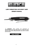
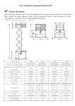
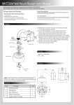
Installation Instructions Page 1 of 3 Universal Accessories, Auxiliary Input Accessory Development January 2004 SUBJECT Auxiliary Audio Input Kit - P/N 82 11 0 142 174 MODEL Z4 (E85) Vehicle Production 10/2002 – On with or without Navigation SUGGESTED INSTALLATION TIME: 0.5 Hours These instructions were developed specifically for BMW vehicles and are not to be compared to any existing instructions for vehicles other than BMW. No methods other than those specified in this document are to be used to install this Auxiliary Audio Input adapter in BMW Z4 vehicles. PARTS INFORMATION Contents of Kit – P/N 82 11 0 142 174 Description AUX input cable Bracket 12-pin Connector 12-pin Connector Cover Mounting Screws (M4x8) Mounting Screw (#4) Cable ties 1/8”x6” Users Manual QTY 1 1 1 1 2 1 3 1 BMW Part Number 84 11 0 302 893 N/A 61 13 8 387 204 61 13 8 384 550 N/A N/A N/A 84 11 0 302 888 DO IT RIGHT THE FIRST TIME, ON TIME, EVERY TIME Installation Manual P/N 01 29 0 309 665 © 2004 BMW of North America, LLC 2 Procedure: 1. Remove the following components using instructions available through TIS: • • • Center vent (1) (REF #64 22 161) Radio (2) (REF #65 11 080) Ashtray Assembly (3) (REF #61 31 057) 2. Route Auxiliary Input cable (1) through ashtray assembly (2) and up through center console to radio cavity (3). 3. Mount Auxiliary Input coin tray in ashtray assembly. Re-install ashtray assembly in center console, taking care not to pinch Auxiliary Input cable upon assembly. 4. Secure coin tray through ashtray assembly to center console with provided screw (1). Warning: Do not over-tighten screw or damage will occur. Hand-tighten only. 5. Locate radio connector (1) in radio cavity. Determine if radio connector (1) already has black 12-pin connector in lower right position: With no connector: 6. Insert AUX black 12-pin connector (2) into empty location. Proceed to Step 12. With connector: 7. Remove black 12-pin connector from rear of radio harness. Remove black housing from 12-pin connector and continue next Step. Installation Manual P/N 01 29 0 309 665 3 To remove terminals from 12-pin AUX connector: 8. Unclip and remove black 12-pin housing (1) from AUX cable connector. 9. Push in metal tabs securing pins into 12-pin connector (2) and slide out all three terminals (3). To insert terminals from AUX cable to existing radio connector: 10. Insert 3 AUX terminals (1) into pin locations (provided in diagram) of 12-pin connector (2). Depending on included options in vehicle, other populated pin locations will vary. White/Red - Slot 3 White/Blue - Slot 4 White/Brown - Slot 10 11. Slide black housing over 12-pin connector, then insert 12-pin connector into main radio connector. 12. Secure cable slack using provided cable ties. 13. Re-install radio and all components removed during installation. 14. Turn radio ON. Press “MODE” button (1) on radio until AUX mode is displayed. Test operation of system. Installation is complete. Please place Auxiliary Input User’s Manual (included in kit) in glove box for customer reference. The following parts will not be reused: • Original ashtray • Ashtray assembly securing screw Vehicle Coding No vehicle coding is required for this retrofit. Installation Manual P/N 01 29 0 309 665