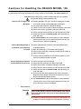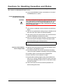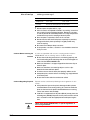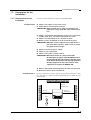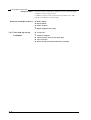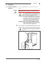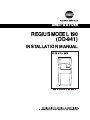
1
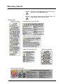
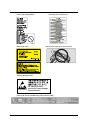
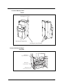
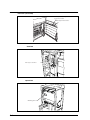
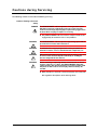
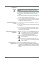
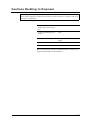
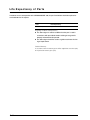
No. 26-2, Nishishinjuku 1-chome, Shinjuku-ku, Tokyo 163-0512, Japan
Table of Contents
Forward ........................................................................................................................................................ i
Features of REGIUS MODEL 190 ..........................................................................................................ii
ALERT SYMBOL MARK ........................................................................................................................iii
OTHER SYMBOL MARKS .....................................................................................................................iii
WARNING NOTICES (SIGNAL WORDS) .............................................................................................iv
Cautions relating to Laws ............................................................................................................................ 1
Warning Labels ...................................................................................................................................... 3
Cautions for Handling the REGIUS MODEL 190 ................................................................................... 8
Cautions for Handling Cassettes and Plates ......................................................................................... 9
Cautions during Servicing .................................................................................................................... 11
Cautions Relating to Disposal .............................................................................................................. 13
Life Expectancy of Parts ...................................................................................................................... 14
1. Overview
1.1
Installation Flowchart ...................................................................................................................... 1-1
1.2
Name of Parts ................................................................................................................................. 1-2
1.3
1.4
1.2.1
REGIUS 190 ......................................................................................................................... 1-2
1.2.2
Option (CS-2/3 LCD Mounting Table with Arm (Table)) ........................................................ 1-3
1.2.3
Option (CS-2/3 LCD Mounting Table with Arm (PC Rack))................................................... 1-4
Preparation for the Installation ........................................................................................................ 1-5
1.3.1
Requirements for the Installation ......................................................................................... 1-5
1.3.2
Tools and Jigs for the Installation.......................................................................................... 1-6
Specifications.................................................................................................................................. 1-7
2. Installation of REGIUS MODEL 190
2.1
Unpacking ....................................................................................................................................... 2-1
2.1.1
Unpacking of REGIUSMODEL 190 ...................................................................................... 2-1
2.1.2
Removing of Fixing Hardware .............................................................................................. 2-9
2.1.3
Checking of Fixing Hardware.............................................................................................. 2-17
2.2
Checking of Input Voltage............................................................................................................. 2-19
2.3
Checking after Installation ............................................................................................................ 2-20
2.3.1
Power Connection............................................................................................................... 2-20
2.3.2
Power ON ........................................................................................................................... 2-20
2.3.3
Connecting to Network ....................................................................................................... 2-21
2.3.4
Fixing of Adjuster Foot........................................................................................................ 2-22
2.3.5
Checking of Cassette.......................................................................................................... 2-22
3. Installation of the Optional Equipment
3.1
Installation of CS-2/3 LCD Mounting Table with Arm (Table) ......................................................... 3-1
3.2
Installation of CS-2/3 LCD Mounting Table with Arm (PC Rack) .................................................... 3-9
3.3
Installation of CS LCD Monitor Fixing Metal. ................................................................................ 3-14
Forward
Direct Digitizer REGIUS MODEL 190 (hereafter referred to as REGIUS MODEL 190) is a
device for reading an X-ray image cassette that uses photostimulable fluorescent material as
an X-ray detector.
This Installation Manual provides the procedures of installing the REGIUS 190 for a field service engineer.
Be sure to carefully read and understand this manual before installing the REGIUS 190.
TRADEMARK
• Microsoft and Windows are trademarks of Microsoft Corporation USA in the U.S. and other countries.
• Windows 2000 is an abbreviation of Microsoft ® Windows ® 2000 Professional operating system.
• The company and product names described in this manual are trademarks of their respective companies.
Please note that the marks, such as ©, ®, and ™ are omitted in this manual.
REGIUS MODEL 190 INSTALLATION MANUAL Ver.1.01 2004.12
i
Features of REGIUS MODEL 190
(1)
With the application of photostimulable fluorescent material, the X-ray images can be digitized directly.
(2)
Wider dynamic range than film, allowing a large amount of diagnostic data acquisition.
(3)
Wide latitude with respect to the emitted X-ray, minimizing fluctuations in exposures.
(4)
Approx. 40 seconds of the cassette feed/load time for reading 14” x 14” cassette at 175µm saves a patient
from waiting.
(5)
Displaying images on the LCD of Console just after exposure allows the doctor to check images on the spot.
(6)
Sampling pitch can be selected from 43.75µm, 87.5µm and 175µm depending on diagnostic purposes.
(7)
New scanning method using a semiconductor laser allows space-saving design. (Installation space: 58cm x
58cm)
(8)
Capability to transfer the digital image data to a host computer allows the system to be used as a PACS dedicated X-ray image acquisition device.
(9)
Up to 16 units of REGIUS 190 can be connected to the REGIUS Console CS-3.
ii
REGIUS MODEL 190 INSTALLATION MANUAL Ver.1.01 2004.12
ALERT SYMBOL MARK
Safety Alert Symbol
This is the industry "Safety Alert Symbol". This symbol draws your attention to items and operations associated with the use of this equipment that could result in danger to yourself and others.
Please read all messages next to alert symbol marks, and follow the directions very carefully.
Before assembling or using this equipment, it is important that you read the instructions and
safety precautions.
OTHER SYMBOL MARKS
The meaning of following symbol marks described in this equipment and this manual is as the
following table.
No.
Symbol
Meaning of Symbol
1
Danger, Warning or Note.
Read the description that bears this symbol.
2
Alternating current
3
Protective earth (ground)
4
OFF (power: disconnection from the mains)
5
ON (power: connection to the mains)
6
Stand by ON/OFF (The main power source will still be ON even when this
is turned OFF.)
7
Dangerous voltage.
8
Type B-applied part.
9
High temperature cautions. The part indicated with this symbol becomes
very hot.
REGIUS MODEL 190 INSTALLATION MANUAL Ver.1.01 2004.12
iii
10
Caution for electrostatic. Internal parts of the device may get damaged due
to electrostatic.
11
Touching the parts indicated with this mark is prohibited. It may cause electrocution or hand may become entangled in the device.
WARNING NOTICES (SIGNAL WORDS)
(1)
Signal words provide an indication of the degree of danger concealed within the product.
(2)
This manual uses three different signal words depending on the probability and severity of injury or damage as
explained below.
DANGER
WARNING
CAUTION
: Indicates an acute hazard that will result in death or serious injury if not avoided.
: Indicates a danger that may result in death or serious injury if not avoided.
: Indicates a danger that may result in medium-level wound or minor injury if not
avoided. It is also used to indicate anticipation of a danger of physical damage
only.
Probability of damage
Bodily injury and
(damage to equipment)
High
Low
Death or serious injury
(serious damage)
DANGER
WARNING
Medium-level wound or
minor injury (minor damage)
WARNING or CAUTION
CAUTION
Physical damage only
(3)
In this manual, in addition to the above warning notices, reference notes providing supplementary explanations are indicated as follows.
<IMPORTANT>Indicates a supplementary note.
iv
CAUTION
REGIUS MODEL 190 INSTALLATION MANUAL Ver.1.01 2004.12
CAUTION
The basic cautions to be observed when installing or
operating the REGIUS MODEL 190 are described in
this chapter. Be sure to read the descriptions in this
chapter and drive the users home to them.
C au t io n s re la t in g t o La w s
Following cautions must be observed when handling the REGIUS MODEL 190 and become thoroughly familiar with the correct method of usage.
Cautions relating to Laser
Regulations
WARNING
The reader device uses a laser light and high voltage.
NEVER remove the external panel.
If you remove the external panel, you may be exposed to laser
light or receive an electric shock.
Specifications of laser unit on the REGIUS MODEL 190 are:
Class: IIIb*
Medium: Semiconductor laser
Wavelength: 660 nm
Maximum output: 80 mW (CW)
* The REGIUS MODEL 190 is a laser class-1 product.
Be certain to comply with any and all laws and government regulations including electric codes
and utility regulations regarding the installation and operation of this equipment.
Precautions to be observed when using medical electrical equipment (to ensure safety and prevent danger)
1. Ensure that only a trained or approved operator uses the equipment.
2. When installing the equipment, observe the following precautions.
(1) Install the equipment in a location where it is not exposed to water.
(2) Install the equipment in a location where there is no likelihood of being
adversely affected by atmospheric pressure, temperature, humidity, drafts,
light, dust, or air containing salt, or sulfur, etc.
(3) Install the equipment in a stable location. Do not install it on an inclined
surface and avoid vibration or shock (including during transportation).
(4) Do not install the equipment in a location where chemical reagents are
stored or where chemical fumes may be present.
(5) Check the frequency, voltage and allowable current (or power consumption) of the power source.
(6) Confirm the conditions of the batteries (how exposed they are, or their
polarity).
(7) Ground the equipment well.
3. Before using the equipment, observe the following precautions.
(1) Check the contact state of the switches, the polarity dial setting, and the
various meters, and confirm that the equipment operates normally.
(2) Make sure that the equipment is well grounded.
(3) Make sure that all the cables are connected correctly and safely.
(4) Using two X-ray devices at the same time may result in an incorrect diagnosis or hazards to people.
So, extreme care should be taken.
(5) Check the batteries.
<IMPORTANT>Should this manual become not readable due to any reason, replace it with a new one
which is available at charged basis.
REGIUS MODEL 190 INSTALLATION MANUAL Ver.1.01 2004.12
C-1
4. When using the equipment, observe the following precautions.
(1) Be careful not to exceed the time period and the amount of X-rays
required for diagnosis or treatment.
(2) Always monitor the entire equipment and a patient for safety.
(3) If an abnormality occurs on the equipment or a patient, take appropriate
measures (i.e. turn off the equipment ensuring the safety for patient, etc.),
to ensure patient protection.
(4) Do not allow a patient to touch the equipment.
5. After using the equipment, observe the following precautions.
(1) Return the switches and dials to their original positions in the specified
procedure, and turn the equipment OFF.
(2) When disconnecting the cables, do not pull the cables or apply an excessive force to them.
(3) Observe the following precautions concerning the storage location.
• Store the equipment in a location where it is not exposed to water.
• Store the equipment in a location where there is no likelihood of being
adversely affected by atmospheric pressure, temperature, humidity,
drafts, light, dust, or air containing salt, or sulfur, etc.
• Store the equipment in a stable location. Do not store it on an inclined
surface and avoid vibration or shock (including during transportation).
• Do not store the equipment in a location where chemical reagents are
stored or where chemical fumes may be present.
(4) Keep all accessories, cables, terminals, etc. neatly after cleaning them.
(5) Be sure to keep the equipment clean for next use.
6. In the event that the equipment operates incorrectly or breaks
down, do not try to repair it yourself. Have a trained engineer to
repair it.
7. Never attempt to modify the equipment.
8. Maintenance and Inspection
(1) Inspect the equipment and its components regularly.
(2) If the equipment has not been used for an extended period of time, clean
the equipment and make sure it operates safely before using it.
9. Operate the equipment correctly according to the Operation
Manual.
Disposing of the system
When disposing of the following used parts, accept the regulations of each local government.
1) REGIUS MODEL 190 main body and components
2) REGIUS MODEL 190 packing materials
3) REGIUS MODEL 190 accessories, and their packing materials.
Fluorescent medium which contains toxic substance is used on the REGIUS Plate. Replacement
and disposal of the REGIUS Plate should be carried out only by qualified service engineer.
<IMPORTANT>Should this manual become not readable due to any reason, replace it with a new one
which is available at charged basis.
C-2
REGIUS MODEL 190 INSTALLATION MANUAL Ver.1.01 2004.12
War n i ng L a b e ls
Warning and Caution labels stuck on the REGIUS 190 are as follows.
• Warning Labels
• Warning for LCD fall
CAUTION
To prevent accident during servicing, never peel or soil
the labels on the REGIUS MODEL 190.
CAUTION
If the label gets soiled or falls off, and the caution is no
Longer legible, replace it with a new one.
• Warning for Cassette Ejection Slot
• Warning for Cassette Magnetizing Plate
• Warning for High Temperature
• Warning for Steel Belt
• Warning for High Temperature
REGIUS MODEL 190 INSTALLATION MANUAL Ver.1.01 2004.12
C-3
• Warning for Laser (External)
• Warning for Foreign Object
• Warning for Laser
•Do not place anything on the inner shelf.
• Warning for Electrostatic
Be careful of static
electricity it may damage
the electronics.
• Warning for CS-2/3 LCD Mounting Table with Arm (Table)
C-4
REGIUS MODEL 190 INSTALLATION MANUAL Ver.1.01 2004.12
• Location of Warning Labels
Exterior
Warning for LCD fall
Warning for Ejection Slot
Warning for Laser (Exterior)
Transport Unit/Cassette Magnetizing Plate
Warning for Magnetizing Plate
Warning for
High Temperature
Warning for
Foreign Object
Warning for High
Temprerature (erasure)
REGIUS MODEL 190 INSTALLATION MANUAL Ver.1.01 2004.12
C-5
Front Door (inner shelf)
Do not place anything
on the inner shelft
Warning for Electrostatic
Steel Belt
Warning for Steel Belt
Optical Unit
Warning for Laser
C-6
REGIUS MODEL 190 INSTALLATION MANUAL Ver.1.01 2004.12
Warning for CS-2/3 LCD Mounting
Table with Arm (Table)
Warning for CS-2/3 LCD Mounting Table
with Arm (Table)
CS-2/3 LCD Mounting Table with Arm (Table)
REGIUS MODEL 190 INSTALLATION MANUAL Ver.1.01 2004.12
C-7
C au t i o n s f o r Ha n d lin g the R E G I U S MOD E L 1 9 0
The following information should be read before proceeding with maintenance work. Those who are involved in servicing should become thoroughly familiar with these cautions relating to normal handling of the REGIUS MODEL 190.
CAUTION Failure to observe the cautions set out below will cause personal
injury and/or damage to the equipment itself.
Cautions prior to Usage of the
• Cautions detailed in the user's manual accompanying the product must be carefully read and thoroughly understood.
Equipment
•
•
•
•
•
The power cable should be checked for damage.
Check to ensure that the earth terminals are properly connected.
Check that all cables are properly and firmly connected.
Check to ensure that the LCD panel is not cracked or fractured.
Check to ensure that the REGIUS MODEL 190 is operating normally and safely.
• The REGIUS MODEL 190 is furnished with air intake and outlet
vents to prevent any rise in the internal temperature of the unit:
ensure that these vents are not blocked.
Cautions Regarding Storage of
the Product when Temporarily
out of Use
Cautions Regarding Usage after
an Extended Period of None-Use
• Power supply breakers should be switched off following prescribed procedures.
•
•
•
•
When disconnecting, be sure to hold cables properly.
•
•
•
•
•
Check the power cables for damage.
All accessories and cables should be cleaned and set in order at
the place of storage.
In order to prevent problems the next time the product is used,
the place of storage should be cleaned.
Check that earth terminals are properly connected.
Check that all cables are properly and firmly connected.
Check to ensure that the LCD panel is not cracked or fractured.
Check to ensure that the REGIUS MODEL 190 is operating normally and safely.
• Use of the unit with other equipment may result in erroneous
diagnosis or pose danger: under such circumstances, the unit
must be operated with utmost caution.
• The REGIUS MODEL 190 is furnished with air intake and outlet
vents to prevent any rise in the internal temperature of the unit:
ensure that these vents are not blocked.
Other Cautions
WARNING
If the REGIUS MODEL 190 produces any unusual noise, odor or
smoke, power should be switched off immediately. Power should
not be restored until the cause has been detected and the problem resolved.
• The Ethernet terminal should not be used for any other purpose, for
example connection to telephone lines, than Ethernet connection.
C-8
REGIUS MODEL 190 INSTALLATION MANUAL Ver.1.01 2004.12
C au t io n s f o r Ha n d l i ng C a sse tte s a nd P l a te s
The user should become thoroughly familiar with the following cautions before handling REGIUS cassettes
(RC-110 Series) and REGIUS Plates (RP-3 Series)
• In this manual, REGIUS cassettes are referred to as "cassettes"
and REGIUS plates as "plates."
Cautions Regarding Photo-stimulated Fluorescent Coating
WARNING
The surface of the plate incorporates a photo-stimulated fluorescent coating which is potentially harmful if ingested. In the event
of leakage of the fluorescent coating (milky white) due to substantial damage to the protective layer on the plate, the following
measures should be taken.
• If the coating is swallowed, a doctor should be consulted immediately.
• If the eyes are exposed to the coating, the eyes should be rinsed
with clean water and a doctor consulted immediately.
• If the coating comes into contact with the skin, the affected area
should be immediately rinsed with clean water.
• Even if the coating has not been ingested, care must be taken to
ensure that no part of the body is contaminated and the plate
disposed of following prescribed procedures.
When disposing the REGIUS Plate, accept the regulations of each local
government.
Cautions to Ensure Maintenance of Image Quality
• Constant care must be taken to ensure that the reading surface
of the plate is not damaged or soiled.
• Any contaminant (dust, etc.) that has attached to the reading
surface of the plate should be removed by cleaning immediately.
• As for films, gloves must be worn when handling plates.
• Ensure that plates are not exposed to sunlight.
• Any procedures involving exposure of the plate to fluorescent
light, such as cleaning, should be finished as quickly as possible
and the plate immediately replaced in the cassette upon completion of the procedure.
• Care must be taken to ensure that the front plate does not
become damaged or soiled.
REGIUS MODEL 190 INSTALLATION MANUAL Ver.1.01 2004.12
C-9
Cautions Regarding Transportation and Storage
• Temperature and humidity levels must be maintained within the
following specified ranges.
Before unsealing the plate
After unsealing the plate
Temperature
10:~40:
10:~30:
Humidity
80%RH or lower (without condensation)
• Do not expose the plate to X or γ rays.
• If the cassette is transported or stored in its packing, ensure that
•
•
•
•
Cautions Before Inserting the
Cassette
the cassette is kept in horizontal position. Storage of cassettes
in vertical position for extended periods or in a high-temperature
environment may result in warping of the back plate.
Once the plate is unpacked, store it in the cassette.
Do not store the front and back plates separately. In particular,
storage of the back plate separately in angled position may
result in warping.
Be careful not to drop or bump cassettes.
As for previous cassettes, cassettes in use should be stored vertically in a rack.
In order to avoid problems with cassette conveying operation inside the
REGIUS MODEL 190, the following cautions should be observed:
• Ensure that the locking mechanism is functioning properly and
check for bending or other damage. Do not insert damaged cassettes into the REGIUS MODEL 190.
• Make sure that there is no paper clipped into the memo clip on
the back plate.
• Make sure that there are no foreign objects such as clips
between the front and back plates.
• In order to ensure that the back plate properly adheres to the
• absorption plate, check that there is nothing (e.g. tape) adhered
to the back plate.
• Ensure that the bar code has not become soiled.
Cautions Regarding Disposal
WARNING
C-10
Disposal must be carried out by following the local regulations in each
country.
• If the protective layer on the plate is damaged and the photostimulated fluorescent coating leaking, be careful to handle the
plate so that none of the photo-stimulated fluorescent coating
comes into contact with the body.
• Lead foil is incorporated into all plates (RP-3S) except plates for
mammograms (RP-3M). Disposal of such plates must be carried
out in accordance with the appropriate waste disposal regulations.
When disposing the REGIUS Plate, accept the regulations of
each local government.
REGIUS MODEL 190 INSTALLATION MANUAL Ver.1.01 2004.12
C au t io n s d u r in g S e r v i c i ng
The following cautions must be observed during servicing.
Cautions Relating to Personal
Safety
DANGER
The REGIUS MODEL 190 incorporates a laser generator (class
IIIb). Direct exposure of the body or the eyes to the laser will
result in serious injury. Special purpose protective goggles must
be worn while carrying out repairs or servicing.
• Only REGIUS MODEL 190 units with the multiple interlocks disengaged may be treated as class-I laser products.
WARNING
The REGIUS MODEL 190 incorporates high-voltage parts which
pose the risk of electrocution if touched.
WARNING
To minimize risk, only properly trained service personnel are
allowed to remove covers or handle internal components, etc.
WARNING
When in the proximity of moving parts such as motors, care must
be exercised to ensure that parts of the body or clothing do
become tangled in the mechanism.
WARNING
Before removing or replacing internal circuit boards, or disconnecting connectors or cables, the REGIUS MODEL 190 power
supply must be switched off. Carrying out such procedures with
the power on will result in serious injury and must always be
avoided.
• Work procedures should be carried out properly and safely with
due regard the descriptions of the warning labels.
REGIUS MODEL 190 INSTALLATION MANUAL Ver.1.01 2004.12
C-11
Cautions Relating to Power
Supply Voltage
WARNING
The voltage supply to the REGIUS MODEL 190 is AC110V or
higher. To avoid electrocution, the following cautions must be
observed:
• Check that the REGIUS MODEL 190 earth is properly connected.
• Ensure that all cables are properly connected and check for
damage.
• Before carrying out work which may involve touching power supply lines, the power supply must be switched off.
• In cases where the power supply must be left on to carry out, for
example voltage measurement, every precaution must be taken
to avoid contact with power supply lines.
Cautions Relating to Lithium
Batteries
The SCB2 (System Control Board) in the REGIUS MODEL 190 incorporates a lithium battery.
• Unless given specific instructions, the lithium battery should not
be removed.
• In cases where the lithium battery must be removed, care must
be exercised to avoid exposure to fire or water. Such exposure
may cause the battery to explode.
Cautions Relating to Damage to
the Equipment
Cautions Relating to the
REGIUS Consoles
CAUTION
The electronic circuits in the REGIUS MODEL 190 may
be damaged by static electricity. The main body and
any electrical parts removed should be handled with
due care during installation and/or repairs.
CAUTION
An earthing strap should always be worn when handling circuit boards.
CAUTION
Never loosen the screws painted in white. Loosening
these screws may disable the restoration of the normal
status in the field.
• Do not install the REGIUS Console directly on the floor.
• In the case that a vibration may be applied to the REGIUS Console when servicing the REGIUS Console, always shut down the
REGIUS Console first, and wait for 30sec or more before starting
the work.
C-12
REGIUS MODEL 190 INSTALLATION MANUAL Ver.1.01 2004.12
C au t io n s R e la t in g to D i sp o sa l
For the purposes of disposal, this product must be handled in accordance with the appropriate
waste disposal regulations. Disposal of the product must be carried out in accordance with local
ordinances and regulations.
Part that should be disposed
of observing the local regulations
Location
Photo-stimulated fluorescent
coating
Plate
Lead foil
Plate (except for mammo and long
object)
Lithium battery
SCB2 (System Control Board)
Fluorescent tube
LCD panel
Main unit and packing material for optional equipments should also be
disposed of observing the local regulations.
REGIUS MODEL 190 INSTALLATION MANUAL Ver.1.01 2004.12
C-13
L i fe E xp e c t a n c y o f P a r ts
In order to ensure safe operation of the REGIUS MODEL 190, the part listed below should be replaced or
serviced before its life expires.
Part
Life Expectancy
Eraser lamp
approx. 10000 shots
Regarding the Above Life Expectancy
• The above figure is valid on condition that the part is used in
accordance with prescribed cautions relating to usage and is
properly maintained and inspected.
• The above figure should be used as a guide to estimate the timing of replacement.
Period of Warranty
In accordance with the warranty, parts will be supplied at cost after expiry
of the period of warranty (one year).
C-14
REGIUS MODEL 190 INSTALLATION MANUAL Ver.1.01 2004.12
Chap1
Overview
Overview for the installation of REGIUS MODEL
190 is described in this chapter.
1.1 Installation Flowchart
1.1
Installation Flowchart
Follow the flowchart below in order to facilitate the installation of the
REGIUS MODEL 190.
Refer to
"2.1.1 Unpacking of REGIUSMODEL 190"
Unpacking
Move where the REGIUS MODEL 190 is installed
Removing the fixing hardware
Connecting the power cable
Checking the stand-alone operation
"2.1.2 Removing of Fixing Hardware"
"2.3.1 Power Connection"
"2.3.2 Power ON"
Network connection
Refer to Installation/Service Manual for CS3/CS-1.
Checking the output image
Refer to Installation/Service Manual for CS3/CS-1.
Backing up the CF data
Refer to Installation/Service Manual for CS3/CS-1.
Fixing the main unit with adjuster foot
CAUTION
"2.3.4 Fixing of Adjuster Foot"
Be certain to comply with any and all laws and government regulations including electric codes and utility
regulations, regarding the installation and operation of
this equipment.
REGIUS MODEL 190 INSTALLATION MANUAL Ver.1.01 2004.12
1-1
1.2 Name of Parts
1.2
Name of Parts
1.2.1 REGIUS 190
[operation] Switch
LCD Panel
Cassette Ejection Lamp
Top Cover
"operation" Lamp (Green)
[erase] Switch
Front Top Cover
"erase" Lamp
Insertion Guide
[eject] Switch
"READY" Lamp
Right Cover
Ejection Plate
Insertion/Ejection Unit
Front Cover
Front Cover
Ethernet Port
Exhaust Duct
Left Cover
Rear Cover
Exhaust Duct
AC Inlet
Power Breaker
1-2
REGIUS MODEL 190 INSTALLATION MANUAL Ver.1.01 2004.12
1.2 Name of Parts
1.2.2 Option (CS-2/3 LCD
Mounting Table with
Arm (Table))
CS-2/3 LCD Mounting Table
ERRO
R
OK
CS-2/3 LCD Arm
CS-2/3 LCD Mounting Table
with Arm (PC Rack)
REGIUS MODEL 190 INSTALLATION MANUAL Ver.1.01 2004.12
1-3
1.2 Name of Parts
1.2.3 Option (CS-2/3 LCD
Mounting Table with
Arm (PC Rack))
CS LCD Monitor Fixing Metal
<IMPORTANT>Please note that the CS LCD Monitor Fixing Metal
and the CS-2/3 LCD Mounting Table with Arm
(Table) are different in shape and purpose. The CS
LCD Monitor Fixing Metal cannot be installed in
combination with the CS-2/3 LCD Mounting Table
with Arm (Table).
1-4
REGIUS MODEL 190 INSTALLATION MANUAL Ver.1.01 2004.12
1.3 Preparation for the Instal-
1.3
Preparation for the
Installation
1.3.1 Requirements for the
Installation
Installation Site
Ensure that the installation site meets the condition below.
• Where is not subject to any water or wax.
• Where doesn’t receive a direct sunlight.
<IMPORTANT>If the insertion slot is subject to the direct sun
light, the accuracy of the bar code reader may be
lost.
• Where is not affected or damaged by air pressure, temperature,
humidity, wind, dust, salt content, flammable gas, sulfur.
• Where is not affected by the tilt, vibration or shock.
• Where is not on the OA floor or the bit for electrical piping.
<IMPORTANT>When the caster or adjuster foot of the device is
placed on these surfaces, artifact such as streak
may appear on the image.
• Where no chemical agent is stored.
• Where no gas is generated.
• Where is away from a source of noise.
<IMPORTANT>Horizontal streaks (4~5 lines interval with
20~60steps) may appear when the REGIUS 190 is
installed nearby the high frequency therapy equipment. Widen the distance from the high frequency
therapy equipment or direct the antenna of the
equipment not against the REGIUS 190.
• Where is wide enough to go through when the cables are connected.
• Where the exhaust duct is not blocked.
Installation Space
Ensure in advance that there is enough space (shown below) for installation. The value in ( ) shows the space required for the installation or maintenance work.
At least
100(600)mm
At leaset
100(600)mm
At least
100(600)mm
Rear
At least
700mm
Front
REGIUS MODEL 190 INSTALLATION MANUAL Ver.1.01 2004.12
1-5
1.3 Preparation for the Instal-
Carrying-in Route
Ensure that there is no bump or gradient, that may cause damage to
the device, in the carrying-in route.
In addition, ensure that the entrance of the installation site is wide
enough for the device to come through.
Dimension and Weights of Device
1.3.2 Tools and Jigs for the
Installation
1-6
•
•
•
•
Width: 580mm
•
•
•
•
•
Cutter knife
Depth: 580mm
Height: 1230mm
Weight: Approximately 170kg
Phillips Screwdriver
26mm Spanner (for fixing the adjust foot)
Long-nose plier
Gloves (for work performed around the steel belt)
REGIUS MODEL 190 INSTALLATION MANUAL Ver.1.01 2004.12
1.4 Specifications
1.4
Specifications
Device Type
Direct Digitizer DD-941
Model Name
REGIUS MODEL 190
CODE No.
Safety Standard
Film Size (Note 1)
0676
IEC60601-1, IEC60825
14"X17"/14"X14"/11"X14"/10"X12"/8"X10"/24X30cm/18X24cm
Mammography * : 24X30cm/18X24cm
Pantomography : 15x30cm
Sampling Pitch (Note 2)
Maximum Resolution
Digital Gradation Level
Cycle Time
Cassette Feed/Load Time (Note 3)
Slots
Dimensions
43.75µm * , 87.5µm and 175µm
7080x9480
4096 steps12bit
90 sh/hr (14"x 14"/175µm)
approx. 40sec.(14"x 14"/175µm)
Insertion x 1 (+1 stack)
Exit x 1 (4 cassettes in stack)
580(W)580(D)1230(H) mm
Weight
approx. 170kg (excluding the cassette)
Power Supply
AC100 ~ 240V±10% (50/60Hz), 1.1kw
Operation Condition
Storage/Transportation Condition
Noise Level
Classification
Electromagnetic Conformity
15 ~ 30:/35 ~ 80RH% (no condensation)
–10~40:/10 ~ 95RH% (no condensation)
60dB or less
Class II (510K)
EMC Domestic Voluntary Control for medical use has been declared.
(IEC06061-1-2, 2001)
Accessories
Options
Power Cable, Operation Manual
REGIUS Cassette, REGIUS Console, JM, JM-BOX
Note 1: * ; Exept the USA.
Note 2: * ; A separate license is required for the optional sampling pitch (43.75µm).
Note 3: Cassette Feed/Load Time ; Time required between cassette insertion and cassette exit.
REGIUS MODEL 190 INSTALLATION MANUAL Ver.1.01 2004.12
1-7
1.4 Specifications
1-8
REGIUS MODEL 190 INSTALLATION MANUAL Ver.1.01 2004.12
Chap2
Installation of
REGIUS MODEL 190
2.1 Unpacking
2.1
Unpacking
2.1.1 Unpacking of REGIUSMODEL 190
WARNING
Unpack the REGIUS MODEL 190 and move it where it should be
installed.
Two or more persons are required to unload the REGIUS
MODEL170 from the skid in order to avoid a turnover accident.
CAUTION
Unpack the REGIUS MODEL 190 after placing the crate
on the level floor. Unpacking the REGIUS MODEL 190
on the inclined floor, it may slip from the skid.
<IMPORTANT>Unpacking the REGIUS MODEL 190 immediately after
it is carried in a facility may cause condensation due
to the difference in temperature between the outside
and room air. In order to avoid the condensation,
leave the device about 1 hour after it is carried in.
<IMPORTANT>When unpacking the REGIUS MODEL 190 in a place
other than the installation site, ensure that there is no
bump or obstacle in the carrying-in route.
1.
Using a cutter knife, cut the fixing band with holding it by one hand.
CAUTION
DON’T stand in front of the fixing band. The fixing band
is strained tightly so that it may hit you at the time when
it is cut.
Fixing Band (2pcs)
Cutter Knife
REGIUS MODEL 190 INSTALLATION MANUAL Ver.1.01 2004.12
2-1
2.1 Unpacking
2.
Remove the lid from the container box.
Lid
3.
Bring out the packing styrofoam (2pcs) and parts box (1pc) on top
of the device.
Following items are packed in the parts box.
•
•
•
•
Warranty
Check List
Operation Manual
Declaration of conformity
Be sure to give these 4 items above to the user after installation.
• Accessory List
• Power Cable
• Collection Bag for Fixing Hardware
Packing Material
Parts Box
4.
Cut the tape fixing the bottom corners of the outer carton (4 corners).
2-2
REGIUS MODEL 190 INSTALLATION MANUAL Ver.1.01 2004.12
2.1 Unpacking
5.
Turn left the knobs (3pcs) in the “Lockpiece”, and remove them.
Use a long-nose plier to easily turn the knob of the lockpiece.
Lockpiece (3pcs)
6.
Knob
Pull out all 3 lockpieces from the outer carton.
REGIUS MODEL 190 INSTALLATION MANUAL Ver.1.01 2004.12
2-3
2.1 Unpacking
7.
Open the outer carton of the crate, and remove it.
Crate
8.
Cut the tape to remove the slope, with supporting it so that it
doesn’t fall over.
CAUTION
Cutting the tape without supporting the ramp may
cause fall over trouble, resulting in serious damage to
you.
The clamp is put on the back side of the ramp, which will be used in the
procedure 11.
Ramp
Tape
2-4
REGIUS MODEL 190 INSTALLATION MANUAL Ver.1.01 2004.12
2.1 Unpacking
9.
Remove the cushioning styrofoam (2pcs) from bottom of the
REGIUS MODEL 190.
Rear Side
Front Side
Cushioning Materials
10.
Cut the bottom of dust-proof bag to remove it.
CAUTION Be careful not to damage the device with cutter knife.
Dust-Proof Bag
Cut arround the dust-proof bag
REGIUS MODEL 190 INSTALLATION MANUAL Ver.1.01 2004.12
2-5
2.1 Unpacking
11.
Place the ramp in front of the skid. Insert the cramp in the holes on
both of the ramp and skid to joint each other.
Clamp
Hole on the ramp
Hole on the skid
Ramp
12.
Open the front cover.
Fixing Screws (2pcs)
Front Cover
Fixing Parts "A"
13.
Remove the fixing screws (2pcs) to remove the fixing hardware “A”.
• The fixing hardware "A" is mounted in bottom front of the REGIUS
MODEL 190 in order to press against the cushioning material. The fixing hardware has to be removed in advance to avoid hitting an obstacles during displacement.
14.
2-6
Close the front cover.
REGIUS MODEL 190 INSTALLATION MANUAL Ver.1.01 2004.12
2.1 Unpacking
15.
Support the REGIUS MODEL 190 from both sides with 2 or more
persons.
WARNING
Two or more persons are required to unload the REGIUS MODEL
190 from the skid in order to avoid a turnover accident. REGIUS
MODEL 190 weighs approximately 170kg. In order to moderate
the speed of the REGIUS MODEL 190 sliding on the slope, 3 or
more persons may be required.
CAUTION
Be sure to follow the items below while unloading the
REGIUS MODEL 190. The outer cover may be damaged
if the device is held with improper forces.
• Don't lift the front cover by holding the bottom of the cover.
• Don't hold the ejection plate.
• Don't lift the device by holding the handle on the rear side.
Ejection Plate
Handle
Bottom of the Front Cover
REGIUS MODEL 190 INSTALLATION MANUAL Ver.1.01 2004.12
2-7
2.1 Unpacking
16.
Lift the REGIUS MODEL 190 approximately 1 cm high, and lower it
until the front caster contacts the slope.
17.
Slowly unload the REGIUS MODEL 190 from the skid.
<IMPORTANT>Handle the REGIUS MODEL 190 as slow as possible in order to avoid physical shock when it contacts the floor.
18.
Transport the REGIUS MODEL 190 to the place where it should be
installed.
2-8
REGIUS MODEL 190 INSTALLATION MANUAL Ver.1.01 2004.12
2.1 Unpacking
2.1.2 Removing of Fixing
Hardware
Remove the fixing hardware which supports the REGIUS MODEL 190
while transporting.
DANGER
1.
Don’t touch the steel belt. (Refer to the procedure 9) The edge of
the steel belt is sharp, which may seriously cut fingers.
Remove the fixing screws (6pcs) to remove the fixing hardware “B”.
• The fixing hardware "B" fixes the transport unit.
Fixing Hardware "B"
2.
Fixing Screws (6pcs)
Remove the fixing screws (2pcs) to remove the light shielding cover
(bottom).
Light-Shielding Cover(bottom)
Fixing Screws (2pcs)
REGIUS MODEL 190 INSTALLATION MANUAL Ver.1.01 2004.12
2-9
2.1 Unpacking
3.
Insert the light shielding cover, with its arrow printed side down, to
the slit of the REGIUS MODEL 190.
• There is a slit in the bottom of the REGIUS MODEL 190 in which the
bottom cover should be inserted. The position of the slit is difficult to
be located. Touch it by hand to locate its precise position before
inserting the bottom cover.
Slit
Light-Shielding Cover
Fixing Screws (2pcs)
1
2
4
3
Arrow Mark
4.
Push the bottom cover from its bottom in order to ensure that the
bottom cover is firmly inserted and secured in the slit.
• If there is rattle, the bottom cover hasn’t been secured in the slit.
Insert it again.
Slit
Light-Shielding Cover
GOOD
Bottom of the Device
NG
5.
Secure the bottom cover with 2 screws removed in the procedure 2.
CAUTION
2-10
When transporting the REGIUS MODEL 190, be sure to
ensure that there is no unevenness on the floor. If the
light shielding cover may hit an obstacle in the transport route, which resulting in a damage to the device.
REGIUS MODEL 190 INSTALLATION MANUAL Ver.1.01 2004.12
2.1 Unpacking
6.
If the bundle of cable has been removed in the procedure 2, replace
it to the original position.
7.
Remove the fixing screws (4pcs) to remove the rear cover.
Hold the handle on the rear cover to lift and remove it.
Fixing Screws
(4pcs)
Handles
Rear Cover
8.
Remove the fixing screws (10pcs) to remove the fixing hardware
“C”.
• The fixing hardware “C” secures the sub-scanning unit.
Fixing Screws (10pcs)
Fixing Hardware "C"
REGIUS MODEL 190 INSTALLATION MANUAL Ver.1.01 2004.12
2-11
2.1 Unpacking
9.
Remove the fixing hardware “D”.
<IMPORTANT>When the fixing hardware “D” is removed, check that
the steel belt is aligned to the center of the pulley. If it
is not, gently pushing the tension pulley to check the
belt become loose and then bring the steel belt to the
center while paying attention to the belt edge.
• Fixing hardware D: Styrofoam parts to protect the steel belt.
DANGER
Don't touch the steel belt. (Refer to the procedure 9) The edge of
the steel belt is sharp, which may seriously cut fingers.
CAUTION Wear gloves when working around the steel belt, and be
careful not to cut your finger with the steel belt.
CAUTION
If the sebum is stuck to the steel belt, the rust may be
generated on the belt or the sub-scanning unit will not
work normally.
Fixing Hardware "D"
Steel Belt
2-12
REGIUS MODEL 190 INSTALLATION MANUAL Ver.1.01 2004.12
2.1 Unpacking
10.
Remove the fixing screws (14pcs) to remove the fixing hardware “E”
while lifting up the balance weight.
• The fixing hardware “E” secures the balance weight.
Balancing Weight
Fixing Screws
Fixing Hardware "E"
Fixing Screws
Fixing Screws
11.
Remove the fixing screws (4pcs) that secure the fixing hardware “F”
on the device. Procedure 11 to 15 are for the removal of the fixing
hardware “F”.
Fixing Screws
12.
Open the front cover.
REGIUS MODEL 190 INSTALLATION MANUAL Ver.1.01 2004.12
2-13
2.1 Unpacking
13.
Remove the handle from its holder on the front cover to fit it in the
adapter of the transport motor.
Adapter
Toward you
Toward
Home Position
Handle
14.
Turn the handle clockwise until the transport unit tilts to its limit.
Be sure to ensure the direction of the light shielding cover before
turning the handle. (Refer to the Procedure 3.)
CAUTION
15.
If the convex side of the light shielding cover faces up,
the convex side will be pushed up by the transport unit,
which resulting in a damage to the light shielding cover.
Remove the fixing screws (4pcs) to remove the fixing hardware “F”.
• The fixing hardware “F” secures the cassette magnetizing plate from
under side.
Magnetizing Plate
Fixing Screws (4pcs)
Fixing Hardware "F"
16.
Lift the balance weight until it reaches the top end.
• As the balance weight is lifted up, the cassette magnetizing plate will
be lowered accordingly.
2-14
REGIUS MODEL 190 INSTALLATION MANUAL Ver.1.01 2004.12
2.1 Unpacking
17.
Remove the fixing hardware “G” from the cassette magnetizing
plate.
• The fixing hardware “G” protects the cassette magnetizing plate from
top side, magnetically sticking to it.
Access the front
of device for work
Right Cover is removed.
The device is viewed from the right side.
Fixing Hardware "G"
Cassette Magnetizing Plate
REGIUS MODEL 190 INSTALLATION MANUAL Ver.1.01 2004.12
2-15
2.1 Unpacking
18.
Turn the handle counterclockwise until the right gear cover (blue)
reaches the home position mark.
Gear Cover (right)
Home Position Mark
19.
20.
Return the handle to the handle holder to close the front cover.
Return the rear cover that has been removed in the procedure 7 to
the original position.
2-16
REGIUS MODEL 190 INSTALLATION MANUAL Ver.1.01 2004.12
2.1 Unpacking
2.1.3 Checking of Fixing
Hardware
Ensure that all 7 fixing hardwares are removed.
CAUTION
Fixing Hardware “A”
If the REGIUS MODEL 190 is started up with any of fixing hardwares left inside, the device will be damaged.
Fixing Hardware “B”
(Refer to the procedure 1 in page 19)
(Refer to the procedure 13 in page 16)
Fixing Hardware “C”
Fixing Hardware “D”
(Refer to the procedure 8 in page 21)
Fixing Hardware “E”
(Refer to the procedure 9 in page 22)
Fixing Hardware “F”
(Refer to the procedure 10 in page 22)
(Refer to the procedure 15 in page 24)
REGIUS MODEL 190 INSTALLATION MANUAL Ver.1.01 2004.12
2-17
2.1 Unpacking
Fixing Hardware “G”
(Refer to the procedure 17 in page 24)
Collecting the Fixing Hardware
Please collect and return the fixing hardware using the fixing hardware
recycle bag.
2-18
REGIUS MODEL 190 INSTALLATION MANUAL Ver.1.01 2004.12
2.2 Checking of Input Volt-
2.2
Checking of Input
Voltage
Remove the rear cover to ensure that the wiring color of the TAP connector suits to the power voltage provided from the facility.
• The wiring color is associated with each power voltage (AC). Following list shows the correspondence between the wiring color
and power voltage.
Wire
Color
Brown
Red
Orange
Yellow
Pink
Blue
Power
Voltage
100V
110V
120V
200V
220V
240V
TAP (Power voltage switching board)
TAP Connector
REGIUS MODEL 190 INSTALLATION MANUAL Ver.1.01 2004.12
2-19
2.3 Checking after Installa-
2.3
Checking after
Installation
Ensure that the REGIUS MODEL 190 has not been damaged while
transporting.
2.3.1 Power Connection
Connect between the AC inlet of REGIUS MODEL 190 and power outlet
of the facility with the power cable.
2.3.2 Power ON
1.
2.
Turn ON the power of the facility.
Turn ON the power breaker of the REGIUS MODEL 190.
LCD Panel
[operation] Switch
"READY" Lamp
Power Breaker
3.
4.
Push the operation switch.
Ensure the items below.
• The LCD panel will show the message “INITIALIZING” and the
counter.
• The counter will increment while initializing.
• When the counter reaches the right end, a message "Network
Error [24000]" will appear.
• The LCD panel will alternately show the default MAC address
and IP address.
Network Error (24000)
MAC: XXXXXXXXX
Network Error (24000)
IP: XXX.XXX.XXX.XXX
2-20
REGIUS MODEL 190 INSTALLATION MANUAL Ver.1.01 2004.12
2.3 Checking after Installa-
5.
After ensuring that the REGIUS MODEL 190 is normal condition,
push the operation switch for at least 5 seconds.
The back light of LCD panel will extinguish.
2.3.3 Connecting to Network
Checks of REGIUS 190 operation shall be performed by the CS-3/CS-1
that is connected with the REGIUS 190.
For details of the network settings, refer to the “REGIUS Console CS-3/
CS-1 Installation/Service Manual”.
Setting the Network
Connect the REGIUS 190 with the CS-3/CS-1 in 1 to 1 configuration,
and set the network condition.
• Refer to the "Network Setting” of the “REGIUS Console CS-3/
CS-1 Installation/Service” manual.
Connecting to the Network
After completing the network setup, connect to the facility’s network.
• Refer to the “Connecting the System” of the ”REGIUS Console
CS-3/CS-1 Installation/Service” manual.
Checking the Output Image
Read the halftone density, and check the image quality.
• Refer to the “Checks and Back up of the Setup Data” of the
“REGIUS Console CS-3/CS-1 Installation/Service” manual.
Back up of CF Card Data
Back up the data in the CF card mounted on the SCB2 of REGIUS
MODEL 190 onto the CS-3/CS-1.
• Refer to the “Checks and Back up of the Setup Data” of the
“REGIUS Console CS-3/CS-1 Installation/Service” manual.
<IMPORTANT>Network data and other setting data that are
unique to each REGIUS 190 are stored in the CF
card. Availability of the back up data will greatly
help set up of the REGIUS 190 when the CF card
needs to be replaced. Always back up the data in
the CF card at the time of installation.
REGIUS MODEL 190 INSTALLATION MANUAL Ver.1.01 2004.12
2-21
2.3 Checking after Installa-
2.3.4 Fixing of Adjuster Foot
After confirming with the facility’s administrator that the installation site is
appropriate, pull down the adjuster foot (2pcs) at the front bottom of
REGIUS MODEL 190 to secure it to the floor.
1.
Rotate and lower the adjuster foots using 26mm(M16) spanner until
the front adjuster foot firmly contact the floor and its rubber part is
slightly depressed. Lower the adjuster foots so that the device does
not mover right and left.
2.
Gently shake the REGIUS MODEL 190, and confirm that it is firmly
fixed to the floor.
2.3.5 Checking of Cassette
• Ensure that 1 or more hours have passed after the REGIUS plate
had been installed to the cassette.
• Ensure that all claws of the cassettes are properly set into the
front panel.
• Be sure to give the declaration of conformity to the user.
2-22
REGIUS MODEL 190 INSTALLATION MANUAL Ver.1.01 2004.12
Chap3
Installation of the
Optional Equipment
3.1 Installation of CS-2/3 LCD Mounting Table with Arm (Table)
3.1
Installation of CS-2/3
LCD Mounting Table
with Arm (Table)
1.
How to install the CS-2/3 LCD Mounting Table with Arm (Table) on the
REGIUS 190 and to the CS-1/2/3 Operation Unit’s Arm is described
below.
Check that all of following components are ready on your hand.
1. CS-2/3 LCD
Mounting Table
with Arm (Table)
(refer to the diagram below)
Delivered
pcs
1)Table front plate
1
2)Table rear assembly
1
3) Fixing plate (left)
1
4) Fixing plate (right)
1
5) Collar
4
6) Edge saddle
1
7) Truss screw (M4x8)
6
8) Truss screw (M4x20)
4
9) Operation Manual
1
1) Monitor Arm
1
2) Arm Cover
2
3) W/SW Ni/Fe(M4x12)
4
4) Cap for Arm Mount Fixing Screw
Hole
2
5) Operation Manual
1
2. REGIUS 190
3. CS-1/2/3 Operation Unit
4. Monitor Arm
1)
5)
2)
6)
3)
7)
4)
REGIUS MODEL 190 INSTALLATION MANUAL Ver.1.01 2004.12
8)
3-1
3.1 Installation of CS-2/3 LCD Mounting Table with Arm (Table)
2.
Place the Table Front Plate on the Upper Top Cover and Table Rear
Plate on the Lower Top Cover of the REGIUS 190 with their two
screw holes at the both edges are facing front.
Table front plate
Table rear assembly
3.
Place the Fixing Plates (Right and Left) on the Table Front Plate and
Table Rear Plate as shown in the diagram, and fix them with six
truss screws (M4x8).
Fixing plate
(left)
Fixing plate (right)
• Use one truss screw (M4x8) each to fix the Fixing Plates to the Table
Front Plate.
• Use two truss screws (M4x8) each to fix the Fixing Plates to the Table
Rear Plate.
Note :
3-2
The screw hole of the Fixing Plate (Right) has a play. Do
not tighten the screw before the final adjustment is completed.
REGIUS MODEL 190 INSTALLATION MANUAL Ver.1.01 2004.12
3.1 Installation of CS-2/3 LCD Mounting Table with Arm (Table)
4.
Hold and lift the table assembled in the step 3, and reverse it and
place on the Top Cover of the REGIUS 190.
5.
Remove four screws from the upper edges of the right and left Side
Covers of the REGIUS 190.
REGIUS MODEL 190 INSTALLATION MANUAL Ver.1.01 2004.12
3-3
3.1 Installation of CS-2/3 LCD Mounting Table with Arm (Table)
6.
Using four screws (M4x20) with collars, fix the Fixing Plates to the
REGIUS.
7.
Unplug all cables when they are connected to the CS-1/2/3 Operation Unit.
3-4
REGIUS MODEL 190 INSTALLATION MANUAL Ver.1.01 2004.12
3.1 Installation of CS-2/3 LCD Mounting Table with Arm (Table)
8.
Remove two “W/SW Ni/Fe (M4 x 12)” and remove the mount when
the mount is attached to the CS-1/2/3.
<IMPORTANT>For the step 7 and 8, work can be facilitated if the
Operation Unit is placed on a flat table with its
touch panel surface facing downward.
REGIUS MODEL 190 INSTALLATION MANUAL Ver.1.01 2004.12
3-5
3.1 Installation of CS-2/3 LCD Mounting Table with Arm (Table)
9.
Fix the Monitor Arm to the rear of the Operation Unit with four
screws of “W/SW Ni/Fe (M4 x 12)”.
3-6
REGIUS MODEL 190 INSTALLATION MANUAL Ver.1.01 2004.12
3.1 Installation of CS-2/3 LCD Mounting Table with Arm (Table)
10.
Place the Monitor Arm on the Table Rear Plate and fix with four
truss screws (M4x29).
CAUTION
11.
The Monitor Arm with the Operation Unit installed is
very unstable. Due care should be taken not to drop or
fall it. When two persons are available for the work, one
holds the Operation Unit while the other is fixing the
screws.
Affix the Screw Hole Concealing Sticker so that the screws attached
in the step 10 are not visible.
12.
When CS-2/3 LCD Mounting Table with Arm (PC Rack), proceed to
"3.2 Installation of CS-2/3 LCD Mounting Table with Arm (PC Rack)".
REGIUS MODEL 190 INSTALLATION MANUAL Ver.1.01 2004.12
3-7
3.1 Installation of CS-2/3 LCD Mounting Table with Arm (Table)
13.
Attach the Edge Saddle to the Fixing Plate (Right).
Bundle and put through the Edge Saddle the cables for mouse, keyboard and barcode reader.
Edge saddle
14.
Connect the cables according the instructions given in the Installation/Service Manual for CS-1/2/3.
3-8
REGIUS MODEL 190 INSTALLATION MANUAL Ver.1.01 2004.12
3.2 Installation of CS-2/3 LCD Mounting Table with Arm (PC Rack)
3.2
Installation of CS-2/3
LCD Mounting Table
with Arm (PC Rack)
How to install the CS-2/3 LCD Mounting Table with Arm (PC Rack) on
the REGIUS 190 is described below.
<IMPORTANT>Before installing the CS-2/3 PC Rack on the
REGIUS 190, it is necessary that the CS-2/3 LCD
Mounting Table with Arm (Table) has been
installed. CS-2/3 LCD Mounting Table with Arm
(PC Rack) cannot be installed by itself alone.
1.
Check that all of following components are ready on your hand.
Option (CS-2/3
LCD Mounting
Table with Arm
(Table))
Delivered
pcs
1) Rack top assembly
1
2) Rack base assembly
1
3) Truss screw (M4x8)
6
4) Operation Manual
1
5) Edge saddle
1
1)
2)
3)
5)
Assembling the CS-2/3 LCD
Mounting Table with Arm (PC Rack)
1.
2.
Install the CS-2/3 LCD Mounting Table with Arm (Table).
Turn off the power of CS-1/2/3, and unplug all cables from the Control Unit.
REGIUS MODEL 190 INSTALLATION MANUAL Ver.1.01 2004.12
3-9
3.2 Installation of CS-2/3 LCD Mounting Table with Arm (PC Rack)
3.
Place the Rack Base Assembly on a flat table as shown in the diagram.
4.
Place the Control Unit (PC) on the Rack Base Assembly with the
direction as shown in the diagram.
<IMPORTANT>Align the rear face to the rear edge of the Rack
Base Assembly.
3-10
REGIUS MODEL 190 INSTALLATION MANUAL Ver.1.01 2004.12
3.2 Installation of CS-2/3 LCD Mounting Table with Arm (PC Rack)
5.
Attach the Rack Top Assembly to the Control Unit as shown in the
diagram.
6.
Fix the Rack Top Assembly to the Rack Base Assembly with four
truss screws (M4x8).
<IMPORTANT>Attach the screws to the holes near the center.
• Fixing the Rack Top Assembly to the Rack Base Assembly allows the
Control Unit to be fixed to the Rack Base Assembly.
REGIUS MODEL 190 INSTALLATION MANUAL Ver.1.01 2004.12
3-11
3.2 Installation of CS-2/3 LCD Mounting Table with Arm (PC Rack)
Installing the CS-2/3 PC Rack to
the CS-2/3 LCD Mounting Table
with Arm (Table)
1.
Engage the crows of the CS-2/3 LCD Mounting Table with Arm (PC
Rack) with the right edge of the REGIUS 190 and fix it with two truss
screws (M4x8).
<IMPORTANT>Insert the CS-2/3 PC Rack to the CS-2/3 LCD
Mounting Table with Arm (PC Rack) into the gaps
at the side of the REGIUS 190, and slightly slide it
toward the rear.
3-12
CAUTION
Make sure that the CS-2/3 LCD Mounting Table with
Arm (PC Rack) is firmly hooked on the REGIUS 190.
Failure in engagement may cause fall of the CS-2/3
LCD Mounting Table with Arm (Table) while the table is
being secured with screws. Due care should be taken.
CAUTION
CS-2/3 LCD Mounting Table with Arm (PC Rack) at this
stage is heavy. Be careful not to drop it when hooking it
at the right side of the REGIUS 190.
CAUTION
Fix the screws immediately after hooking the CS-2/3
PC Rack at the right side of the REGIUS 190. Do not
leave it unscrewed.
REGIUS MODEL 190 INSTALLATION MANUAL Ver.1.01 2004.12
3.2 Installation of CS-2/3 LCD Mounting Table with Arm (PC Rack)
2.
Attach the Edge Saddle to the Fixing Plate (Right).
Bundle and put through the Edge Saddle the cables for mouse, keyboard and barcode reader.
Edge saddle
3.
Connect the cables according the instructions given in the Installation/Service Manual for CS-1/2/3.
REGIUS MODEL 190 INSTALLATION MANUAL Ver.1.01 2004.12
3-13
3.3 Installation of CS LCD Monitor Fixing Metal.
3.3
Installation of CS
LCD Monitor Fixing
Metal.
1.
How to install the CS LCD Monitor Fixing Metal on the REGIUS 190 is
described below.
CAUTION
CS-2/3 LCD Monitor Fixing Metal is to reduce the risk of
the monitor falling down by means of fixing the CS-2/3
Wide View Monitor to the Upper Top Plate of the
REGIUS 190.
Check that all of following components are ready on your hand.
1. Option (CS-2/3
LCD Mounting
Table with Arm
(Table))
Delivered
pcs
1) Collar 1 (Large)
2
2) Collar 2 (Small)
2
3) Holding base
1
4) Holding plate
1
5) Truss screw (M4x8)
2
6) Truss screw (M4x30)
2
7) Operation Manual
1
2. REGIUS 190
3. CS-1/2/3 Operation Unit
1)
2)
3)
5)
4)
2.
3-14
6)
Unplug the LAN cable when it is connected to the REGIUS 190.
REGIUS MODEL 190 INSTALLATION MANUAL Ver.1.01 2004.12
3.3 Installation of CS LCD Monitor Fixing Metal.
3.
Remove two screws from the upper rear of the REGIUS 190.
4.
Sandwich the Holding Plate Base with Collar 1s(Large) and Collar 2s
(Small), and fix the Holding Plate Base with two truss screws
(M4x30) to the REGIUS 190.
Truss screw
Collar 2
(Small)
Holding
base
5.
Collar 1
(Large)
With two truss screws (M4x8), temporary fix the Holding Plate to the
Holding Plate Base that has been fixed in the step 4.
REGIUS MODEL 190 INSTALLATION MANUAL Ver.1.01 2004.12
3-15
3.3 Installation of CS LCD Monitor Fixing Metal.
6.
Place the Control Unit on the REGIUS 190.
<IMPORTANT>Align the rear edge of the stand to the rear edge of
the REGIUS 190.
CAUTION
7.
Please note that the CS LCD Monitor Fixing Metal and
the CS-2/3 LCD Mounting Table with Arm (Table) are
different in shape and purpose. The CS LCD Monitor
Fixing Metal cannot be installed in combination with
the CS-2/3 LCD Mounting Table with Arm (Table).
Adjust the crow of the Holding Plate attached in the step 3 so that
the stand of the Control Unit fits to the crow. Then tighten the
screws.
8.
3-16
Connect the LAN cable that has been unplugged in the step 2.
REGIUS MODEL 190 INSTALLATION MANUAL Ver.1.01 2004.12
" 6-