1
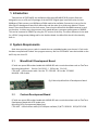
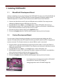
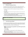
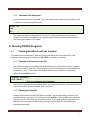
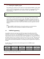
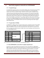
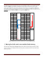
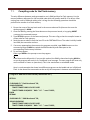
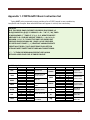
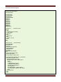
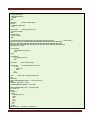
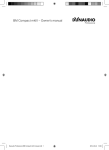
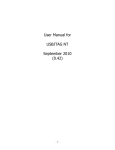
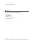
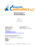
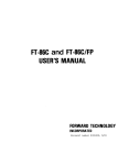
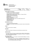
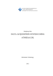
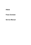
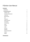
FORTHdsPIC User Manual
Contents
FORTHdsPIC User Manual ......................................................................................................................... 1
1.
2.
Introduction ................................................................................................................................... 2
System Requirements .................................................................................................................... 2
2.1. MicroStick II Development Board ........................................................................................... 2
2.2. Custom Development Board .................................................................................................. 2
3. Installing FORTHdsPIC .................................................................................................................... 3
3.1. MicroStick II Development Board ........................................................................................... 3
3.2. Custom Development Board .................................................................................................. 3
4. Running FORTHdsPIC ..................................................................................................................... 4
4.1. MicroStick II Development Board ........................................................................................... 4
4.2. Custom Development Board .................................................................................................. 4
5. Running FORTH in Interpreter Mode ............................................................................................. 5
5.1. Simple Command Line ............................................................................................................ 5
6. Running FORTH Programs .............................................................................................................. 6
6.1. Creating New Words with the Compiler................................................................................. 6
6.2. FORTH Programming .............................................................................................................. 7
6.3. How Forth programs are stored & run in FORTHdsPIC .......................................................... 8
7. Moving the Forth code to non-volatile (Flash) memory.............................................................. 10
7.1. Compiling code for the Flash memory ................................................................................. 11
7.2. Running an Embedded Application ...................................................................................... 12
Appendix 1. FORTHdsPIC Basic Instruction Set ................................................................................... 13
Appendix 2. Sample Forth programs ................................................................................................... 18
FORTHdsPIC User Manual Vsn 1.0
W.G.Marshall 2014
Page 1
1. Introduction
Two versions of FORTHdsPIC are available as Microchip MPLAB IDE 8.92 projects. Both are
designed to run on a 28-pin DIP package of the dsPIC33FJ digital signal controller series. At least
64KBytes of Flash memory and 16KBytes of RAM need to be available. One version is set up for the
MicroStick 2 development board from Microchip and the other for a third-party Arduino® format
board. The main difference is the clock source; internal on the MicroStick and 8MHz external crystal
on the other. In either case, the processor clock speed delivers a processor performance of 40MIPS.
This can be increased to 70MIPS by using the ‘EP’ version of the chip. The other difference is the need
for a PICkit 3 programmer/debug tool for the Arduino board: the MicroStick has this functionality
built-in.
2. System Requirements
Both these versions can run code in a stand-alone or embedded mode once the user’s Forth code
has been compiled and ‘Flashed’ into program memory. But first FORTHdsPIC must be installed on the
dsPIC chip via a host PC.
2.1.
MicroStick II Development Board
PC with two spare USB sockets loaded with MPLAB IDE and a terminal emulator such as TeraTerm
Microchip MicroStick II Part No. DM330013-2 RS Part No. 749-6445
FTDI UART - USB converter cable Part No. TTL-232R-RPi RS Part No. 767-6200
MiniUSB - USB-A cable
Fig.1 Microchip MicroStick II Development Board
2.2.
Custom Development Board
PC with two spare USB sockets loaded with MPLAB IDE and a terminal emulator such as TeraTerm
Development board with ICSP header pins
Microchip PICkit 3 programmer/debug tool
FTDI UART - USB converter cable (If no USB port available) P/N TTL-232R-RPi RS P/N 767-6200
FORTHdsPIC User Manual Vsn 1.0
W.G.Marshall 2014
Page 2
3. Installing FORTHdsPIC
3.1.
MicroStick II Development Board
All that’s needed for the one-time Flashing of the FORTHdsPIC firmware is the PC with MPLAB, the
MicroStick and a USB cable. The MicroStick has on-board programmer/debug hardware so no
additional equipment is required. The firmware uses the dsPIC internal clock oscillator.
1. Connect the MicroStick to the PC with the USB cable and run MPLAB. There may be some
upheaval as Windows locates a USB driver the first time.
2. Run MPLAB and click on Open… in the Project menu. Select FORTHdsPIC_Microstick_xx.
3. MPLAB might complain it can’t find some files where it expects to find them. It should offer a
link to the correct location and all you have to do is accept.
4. Generate the object code by clicking on the Build All button.
5. Click on the Program button to Flash the dsPIC program memory with the firmware.
3.2.
Custom Development Board
For other types of board including new designs, an external programmer/debug tool will be
required. A standard Microchip ICSP header should be provided to which the PICkit 3 programmer
may be connected. The firmware assumes an external 8MHz crystal is connected.
1. Plug the PICkit 3 into the development board using the ICSP header. Connect the PICkit 3 to
the PC with the USB cable and run MPLAB. There may be some upheaval as Windows locates a
USB driver the first time.
2. Run MPLAB and click on Open… in the Project menu. Select FORTHdsPIC_DIP.
3. MPLAB might complain it can’t find some files where it expects to find them. It should offer a
link to the correct location and all you have to do is accept.
4. Generate the object code by clicking on the Build All button.
5. Click on the Program button to Flash the dsPIC program memory with the firmware.
Fig.2 Arduino-format development board for PIC24/dsPIC
from WIDE.HK. Features ICSP header for
debug/programmer and a USB-UART bridge chip.
FORTHdsPIC User Manual Vsn 1.0
W.G.Marshall 2014
Page 3
4. Running FORTHdsPIC
4.1.
MicroStick II Development Board
Once programmed with the FORTHdsPIC firmware, MPLAB is no longer needed but the USB
connection is still required to power the board. In order to edit, compile and run FORTH code you
will need the PC running a terminal emulator, USB cable and a UART-USB bridge cable.
1. Connect the bridge cable to UART Tx, Rx and Gnd pins of the header on the MicroStick.
Pin 1 : Black
Pin 4 : Orange
Pin 5 : Yellow
2. Plug the other end of the cable into the PC. Again there should be a one-time search for and
loading of a driver.
3. Run the terminal emulator, in my case I use TeraTerm, and make sure it links to the correct
serial COM port with settings 19200baud, 8bits, No Parity and Transmit Delay 200ms. Save the
template so it’s selected whenever the MicroStick is plugged in.
4. The board is powered from the USB link so with the slide-switch set to A, press the RST button
and a title message with FORTH prompt should appear in the emulator window:
FORTHdsPIC Vsn. X.X (C) W.G.Marshall
10 >
4.2.
Custom Development Board
Once programmed with the FORTHdsPIC firmware, MPLAB is no longer needed but the board will
still need to be powered. Power supply and connection to the PC terminal emulator will depend
on the particular board design. In order to edit, compile and run FORTH code you will need a host
PC running a terminal emulator and a USB or UART-USB bridge cable.
1. Either connect the bridge cable to Tx, Rx and Gnd pins of a UART1 header on the board. These
are the pin numbers for a 28-pin DIP package dsPIC33. These pins will be assigned to UART1 by
FORTHdsPIC when it boots up.
Gnd Pin 19 : Black
Rx Pin 21 : Orange
Tx Pin 22 : Yellow
or connect a USB cable to the target board if it has a UART-USB bridge chip fitted.
2. Plug the other end of the cable into the PC. Again there may be a one-time search for and
loading of a driver for the bridge chip.
3. Run the terminal emulator, in my case I use TeraTerm, and make sure it links to the correct
serial COM port with settings 19200baud, 8bits, No Parity and Transmit Delay 200ms. Save the
FORTHdsPIC User Manual Vsn 1.0
W.G.Marshall 2014
Page 4
template so it’s selected whenever the MicroStick is plugged in.
4. The board is powered from the USB link so with the slide-switch set to A, press the RST button
and a title message with FORTH prompt should appear in the emulator window:
FORTHdsPIC Vsn. X.X (C) W.G.Marshall
10 >
5. Running FORTH in Interpreter Mode
From now on operation of FORTHdsPIC is largely independent of the hardware platform. Fig.3
below shows a minimal system for program development based on the MicroStick II fitted with a
dsPIC33 device.
Fig.3 FORTHdsPIC running on a
MicroStick. Communication is via
the TeraTerm window. MPLAB IDE is
open in the background.
5.1.
Simple Command Line
Basic calculations can be performed immediately by typing Forth commands and numbers
separated by spaces after the command prompt, followed by Return. Max length = 80 characters.
5.1.1 Command Prompt
The Command prompt (>) is preceded by a number indicating the number base in use. The
default is decimal (10) and its value is held in the system variable BASE. Typing HEX at the
prompt will change the base to hexadecimal (16); DECIMAL will change it back.
FORTHdsPIC User Manual Vsn 1.0
W.G.Marshall 2014
Page 5
5.1.2 Command Line Interpreter
At the command prompt (>) type: 6 4 * 3 / . not forgetting the spaces, and press Return. The
‘.’ means Print the result on the console.
10 > 6 4 * 3 / .
8 OK
10 >
This simple calculation is equivalent to Print (6 x 4) / 3 but using Reverse Polish notation
instead. This format is very efficient on computers which feature temporary data storage in
the form of push-down or LIFO stacks.
6. Running FORTH Programs
6.1.
Creating New Words with the Compiler
The Command Line Interpreter is great for testing small pieces of Forth code, but for a full
program incorporating structures such as DO…LOOP, a compiler is necessary.
6.1.1 Generate a Forth source code file
Use a basic text editor such as Microsoft Notepad to create a Forth source code or ‘program’
file. Save it on the PC hard-disk. A Forth program consists of at least one new word definition
enclosed by ‘:’ and ‘;’. The simple code example above can be compiled as a new word
definition called CALC like this:
( Program 1: Calculator )
: CALC * SWAP / ;
;
( This is a comment between brackets )
Note that the numbers are not included. When the compiled word CALC is executed it will take
the top three items off the parameter stack to work on.
6.1.2 Running the Compiler
Send the source text file to the FORTHdsPIC compiler. Use the appropriate function on the
terminal emulator to do this. For TeraTerm click on Send file… from the File menu and select
your file to send. FORTHdsPIC just sees the text file as a very long keyboard input: any ‘colon’
definitions are compiled and code saved in the code area of RAM. Any other words are
executed immediately.
FORTHdsPIC User Manual Vsn 1.0
W.G.Marshall 2014
Page 6
6.1.3 Running the compiled program
The vocabulary entry and the run-time code for the new word definition CALC is stored in RAM
memory and will be lost if the power to the board is switched off or the processor RST (Reset)
button pressed. To run CALC with the same numbers as before, type 3 4 6 CALC . at the
command prompt:
10 > 3 4 6 CALC .
8 OK
10 >
The Interpreter reads the command line from left to right and ‘pushes’ the three numbers
onto the Last-In First-Out Parameter Stack in order. When CALC is executed, the top two, 4
and 6 are ‘popped’ off the stack, multiplied together and the result pushed on the stack. The
top two parameters, now 24 and 3 are SWAPped, popped off, the division performed and the
result, 8 pushed back on the stack. Finally the print number command (.) pops the result and
displays it.
Note:
1. Now that CALC is a defined word, it can be used to operate on any three numbers.
2. CALC can be used inside new definitions alongside the standard words.
6.2.
FORTH Programming
It is possible to create one very large colon-definition using just the standard words of the
FORTHdsPIC instruction set. From the debugging point of view and of someone else trying to
understand your work, this is very definitely the worst way to program in Forth. The drawback of
using a push-down stack for storing intermediate results is keeping track, ensuring that each Forth
word begins execution with its operands on top of the stack in the correct order. Following a piece
of source code involves keeping an image of the stack in your mind at every stage. This becomes
difficult with more than three stacked items so annotating a source listing with stack ‘snapshots’ is
essential.
The table below shows the data on the stack during execution of the CALC example.
TOS = Top of Stack
Parameter Stack
TOS
TOS-1
TOS-2
Before *
6
4
3
After *
24
3
After SWAP
3
24
After /
8
Fig.4 State of Parameter Stack as CALC executes
FORTHdsPIC User Manual Vsn 1.0
W.G.Marshall 2014
Page 7
6.3.
How Forth programs are stored & run in FORTHdsPIC
6.3.1 Format & Storage
A compiled Forth program consists of a list of 16-bit address links each pointing to the code for
that word. That code could be the start of another list of addresses or actual executable
machine code. There is a problem though. The dsPIC has what is called a modified Harvard
architecture where data and program memories are separated. This means that executable
code is stored in Program memory, but Forth address links are treated as data and stored in
Data memory. Early versions of Forth ran on microprocessors with a single memory space for
both Data and Program. Fortunately there is a way of ‘fooling’ the dsPIC chip into believing
that an area of Program Flash memory is actually Data RAM. Those familiar with PIC chips will
be aware of the TBLRD and TBLWT instructions which allow data to be read from and written
to program memory. The PIC24/dsPIC devices also have an operating mode called Program
Space Visibility (PSV).
6.3.2 Program Space Visibility
In FORTHdsPIC a 32Kbyte section of program (Flash) space is mapped into data memory (RAM)
beginning at address 8000h. This is why the compiled Forth links all have Bit 15 = 1. The PSV
system is enabled from startup so every time the processor reads data from an address with
Bit 15 set, it gets it from Flash memory not RAM. Here are the Vocabulary and Code entries for
the compiled CALC example:
User Vocabulary Entry in RAM
Address Code
2000
4
Name string length
2001
C
2002
A
Name string
2003
L
2004
C
2005
00
Pointer to Code L
2006
28
Pointer to Code H
User Forth Code in RAM
Address Code
2800
0000 Forth code header
2802
8CBC *
2804
8C3A SWAP
2806
8CD8 /
2808
87FE TRET threaded return
Fig.5 Vocabulary entry and Forth linked code for example CALC program
6.3.3 How FORTHdsPIC runs the CALC example compiled code
Two pieces of code are produced by the Compiler for each ‘colon-definition’. (Fig.5) When
CALC is subsequently typed at the command prompt, the Interpreter scans the vocabulary and
when it finds the correct entry it picks up the Code Pointer and runs EXECUTE. This routine
checks the item at the Code Pointer address, in this case 2800h, to see if it is zero as here,
indicating a Forth linked list follows. The Forth Program Counter (PC) is saved on the Return
Stack and moved on to point to the next item in the list (*) at address 2802h. The contents of
FORTHdsPIC User Manual Vsn 1.0
W.G.Marshall 2014
Page 8
this address 2802h is now loaded as a pointer and the data at this address, 8CBCh, checked to
see if it’s zero. If it is, then the whole process from saving and incrementing the PC onwards is
repeated until a non-zero value is found. In our example CALC, 8CBCh is the address of the
multiply (*) machine code routine, which can now be executed. Now the actual address of the
routine in Program memory is 0CBCh so Bit 15 is masked off to enable a ‘computed goto’ to
take place. Remember Bit 15 is set to trigger the PSV system so the contents of Program
memory location 0CBCh can be read as Data. Once it has been established that it contains
executable machine code, Bit 15 is cleared and the code at 0CBCh executed instead.
The code starting at address 0CBCh is for the single-precision multiply (*) and terminates like
all the machine code routines with a jump to the threaded linker, NEXT. This tiny machine
code routine is the heart of the system, transferring program execution from one link address
to the next. After the divide (/) the linked Forth code CALC ends with TRET which pops the last
PC off the Return stack before jumping to NEXT. As this is the end of the program, control
returns to the Interpreter and the command prompt.
The important point to notice is the difference between executing CALC as a command line
and executing the compiled version.
When you type in a series of commands and data at the prompt (Section 5.1.2) the Interpreter
searches for each one in the Interpreter vocabulary, locates its code and executes it until the
end of the line is reached.
When CALC is compiled (Section 6.1.1) and then run at the command prompt, the Interpreter
pushes the three parameters on the stack before searching all the vocabularies for the CALC
entry. Once the CALC word begins executing the vocabularies are no longer referenced
because the compiled code now contains all the pointers in a list. Hence compiled code will
always run much faster than interpreted code.
Note that the Pointer to Code in the User Vocabulary (Fig.5) does not have Bit 15 set because
the newly compiled code is in RAM. This will change if user code is moved to Flash memory.
(See Section 7)
Take a look at the listing for FORTHdsPIC itself: all the speed sensitive word definitions are in
machine code while those printing to the terminal say, are composed of Forth linked lists.
6.3.4 How FORTHdsPIC runs more complex compiled code
This example serves to show the code generated (Fig.6) when two new user word definitions,
CALC and PRINT are incorporated in the definition of a third, MAIN.
( Program 2: Print results of simple calculation )
: CALC * SWAP / ;
( Perform calculation with top 3 stack items )
: PRINT . CR ;
( Print TOS item followed by NewLine )
: MAIN CALC PRINT ;
( Combine CALC and PRINT into a new word – MAIN )
FORTHdsPIC User Manual Vsn 1.0
W.G.Marshall 2014
Page 9
Fig.6 below illustrates the program flow of the new word MAIN. As before, the command interpreter
searches for MAIN in the vocabulary, and begins execution when it finds the entry and its code
pointer value of 2812. This time however, the pointer links through to a new definition, CALC which
also resides in RAM. Hence the absence of the PSV bit on the link address of 2800. Note again that the
vocabulary entries for CALC and PRINT are not required for MAIN to run.
Vocabulary
Address
Code
2000
2007
200F
4
C
A
L
C
00
28
05
P
R
I
N
T
0A
28
4
M
A
I
N
12
28
Forth Code
Address
Code
Function
2800
0000
8CBC
8C3A
8CD8
87FE
0000
8A52
8900
87FE
0000
2800
280A
87FE
CALC
*
SWAP
/
TRET
PRINT
.
CR
TRET
MAIN
CALC
PRINT
TRET
280A
2812
End
Fig.6 Vocabulary entry and Forth linked code for example MAIN program
7. Moving the Forth code to non-volatile (Flash) memory
Once the Forth code has been debugged while stored in RAM, it can be moved to the dsPIC’s Flash
memory so that it won’t disappear when the device power is removed. It will also ‘auto-boot’ from
power-up or Reset.
FORTHdsPIC User Manual Vsn 1.0
W.G.Marshall 2014
Page 10
7.1.
Compiling code for the Flash memory
The only difference between code generated to run in RAM and that for Flash memory is in the
memory address references for the compiled code which will usually need Bit 15 to be set. After
testing your code in RAM and making sure it is bug-free the following operations should be
performed to transfer it to Flash memory.
1. Ensure the name of the top-level word in the source code text file (the one that runs the
whole program) is MAIN.
2. Clear the RAM by pressing the Reset button on the processor board, or by typing ABORT
<return at the command prompt.
3. Type SETFLSH <return> at the command prompt. This sets a flag so that the compiler knows to
create code for Flash memory.
4. Send the source code file from the host PC to the FORTHdsPIC host. The code is initially loaded
into RAM, but cannot be run here.
5. If no errors appeared on the screen as the program compiled, type FLASH <return> at the
command prompt. FLASH has copied the RAM vocabulary and code space to the
corresponding Flash memory locations.
6. To run the program:
Either type MAIN at the prompt to run the program
or
Press Reset on the Microstick. If you use this method, the RAM is cleared and typing MAIN to
re-run the program will result in an ‘Undefined’ error message. The user program will now only
run from Reset or Power-on (auto-boot). This is the stand-alone or embedded mode.
Here is a code example that shows how different programs can be loaded and run in RAM and
Flash. It also shows that commands can be run by the interpreter in between colon definitions.
( Program 3: RAM versus Flash memory Benchmark Test )
SETFLSH
: FHEADING CR ." Flash Benchmark" CR ;
: MAIN FHEADING
TIMSET TIMSRT 10001 1 DO SP! LOOP
TIMSTP TIMRD 40 M/MOD ." BM1: " 8 F. ." usecs" DROP ;
FLASH
SETRAM
: RHEADING CR ." RAM Benchmark" CR ;
: BENCH RHEADING
TIMSET TIMSRT 10001 1 DO SP! LOOP
TIMSTP TIMRD 40 M/MOD ." BM1: " 8 F. ." usecs" DROP ;
FORTHdsPIC User Manual Vsn 1.0
W.G.Marshall 2014
Page 11
SETFLSH sets the Flash memory flag and the next two colon definitions FHEADING and MAIN
are compiled into RAM accordingly.
FLASH copies the code into Flash memory.
SETRAM clears the Flash flag so subsequent compilation will yield code that will execute in
RAM. The vocabulary and code entries of RHEADING and BENCH are appended to those of the
other two in RAM.
Type BENCH at the prompt and the benchmark program for RAM based programs produces:
RAM Benchmark
BM1: 7501 usecs OK
10 >
Type MAIN at the prompt and the benchmark program for Flash based programs produces:
Flash Benchmark
BM1: 8251 usecs OK
10 >
Both versions will run from the keyboard input because the MAIN vocabulary entry remains in
the RAM and so it can be found by the Interpreter search. Type VLIST to confirm this.
Notice that the Flash-based program takes longer to run than the RAM-based code. This is
because of the increased number of PSV fetches which makes the Flash code about 10%
slower.
When either Flash or RAM-based code ends, control returns to the command prompt.
7.2.
Running an Embedded Application in Flash memory
An embedded program must auto-start from power-up and never return to the command prompt.
However when testing, an exit should be provided otherwise the only way to regain control is to
connect up MPLAB IDE and force a chip erase. FORTHdsPIC will then have to be re-Flashed.
( Program 4: Walks until a key is pressed )
: MAIN BEGIN WALK INKEY 0= WHILE REPEAT ;
This code fragment from a robot control program keeps WALK running in a loop until it detects a
terminal key has been pressed.
( Program 5: Walks for ever )
: MAIN BEGIN WALK AGAIN ;
This code replaces Program 4 only when the complete program is fully debugged! The terminal
can now be disconnected.
FORTHdsPIC User Manual Vsn 1.0
W.G.Marshall 2014
Page 12
Appendix 1. FORTHdsPIC Basic Instruction Set
Typing VLIST at the command prompt provides a list of FORTH words in two vocabularies,
Interpreter and Compiler. New word definitions will appear in a third, User vocabulary.
10 >VLIST
DUP ?DUP DROP SWAP OVER ROT PICK 2DROP 2DUP 2SWAP >R
R> R@ CMOVE FILL @ C@ ! C! ARRAY1D + D+ - * M* U* / M/ /MOD
U/MOD M/MOD */ */MOD 2* 2/ 1+ 1- 2+ 2- NEGATE DNEGATE
ABS DABS S->D +! AND OR XOR NOT TOGGLE = > < U< 0= 0> 0<
MAX MIN . U. D. F. R. ? COUNT TYPE INKEY KEY QUERY EMIT
CR SPACE SPACES DECIMAL HEX .( BASE I J K DPL CODE HERE
SP! DEPTH VLIST FORGET ( : , C, CONSTANT VARIABLE EXECUTE
CREATE ALLOT DOES> ] QUIT ABORT ERASE FLASH SETFLSH
SETRAM TIMSET TIMSRT TIMSTP TIMRD WAIT SVOSET SERVO
( ' [ ; ." IF THEN ELSE BEGIN WHILE REPEAT UNTIL AGAIN
DO LOOP +LOOP LEAVE CASE OF ENDOF ENDCASE
Stack Manipulation
Word
Stack Before
Stack After
n
n
n
DUP
n
?DUP
n
n if n<>0
Action
Duplicate TOS
2DUP
DROP
Stack Before
SWAP
n2
n1
OVER
n1
n2
n2
n1
n2
n3
n1
n2
n2
n1
n2
n1
n2
n3
n
n1
n2
FORTHdsPIC User Manual Vsn 1.0
Exchange TOS and
TOS-1
2SWAP
Copy TOS-1 to TOS
>R
Rotate TOS-2 to TOS
R>
Copy TOS-n to TOS
n = 2 shown
R@
Stack After
nh
nl
nh
nl
Drop TOS
n1
n2
PICK
2DROP
Duplicate TOS if TOS
not equal to zero
n
ROT
Word
n1h
n1l
n2h
n2l
n
Drop DoublePrecision number
nh
nl
nh
nl
n2h
n2l
n1h
n1l
Duplicate DoublePrecision number
Exchange DoublePrecision numbers
Move TOS to
Return stack
n
W.G.Marshall 2014
Action
n
Move Top of Return
stack to TOS
Copy Top of Return
stack to TOS
Page 13
Memory
Word
CMOVE
FILL
Stack Before
Stack After
n
RAM address S
RAM address D
n1
n2
RAM address
RAM address
n
@
RAM address
Action
Copy n bytes from
RAM start address S
to destination D
Fill n1 bytes with
character n2 starting
at RAM address
Read 16-bit number n
at RAM address to
TOS
n
Read byte n at RAM
address to TOS
C@
Arithmetic
Word
Stack Before
Stack After
Action
n1
n2
r
+
n1
n2
r
-
n1
n2
r
*
n1
n2
r
/
M*
n1
n2
rh
rl
U*
n1
n2
rh
rl
r
/MOD
n
nh
nl
n1
n2
r
rem
U/MOD
n1
n2
r
rem
n
nh
nl
n
rh
rl
rem
r
SP to SP signed
addition
n1 + n2 → r
SP to SP signed
subtract
n2 - n1 → r
SP to SP signed
multiply
n1 × n2 → r
SP to SP signed
division
n2 / n1 → r
SP to DP signed
multiply
n1 × n2 → rh,rl
SP to DP unsigned
multiply
n1 × n2 → rh,rl
DP to SP signed
division
(nh,nl) / n → r
SP to SP signed
division & remainder
n2 / n1 → r,rem
SP to SP unsigned
division & remainder
n2 / n1 → r,rem
DP to DP unsigned
division & remainder
(nh,nl) / n → rh,rl,rem
M/
M/MOD
NEGATE
DNEGATE
DADD
nh
nl
rh
rl
n1h
n1l
n2h
n2l
rh
rl
FORTHdsPIC User Manual Vsn 1.0
Word
Stack Before
!
RAM address
n
C!
RAM address
n
Stack After
Action
Write 16-bit
number n to RAM
address
Write byte n to
RAM address
n
Creates 1D array
<name> size n
words
Moves Code
pointer in RAM up
by n bytes
ARRAY1D
n
ALLOT
SP = Single Precision (16-bit) DP = Double Precision (32-bit)
Word
Stack Before
Stack After
Action
n
r
n
r
n
r
n
r
n
r
n
r
n
r
DABS
nh
nl
rh
rl
+!
RAM address
n
2*
2/
1+
12+
2ABS
n
rh
rl
n
n1
n2
n
n1
n2
r
S->D
SP to SP negate
-n → r
*/
DP to DP negate
-(nh,nl) → rh,rl
*/MOD
r
rem
SP to SP signed
multiply by 2
n×2→r
SP to SP signed
divide by 2
n/2→r
SP to SP signed
increment
n+1→r
SP to SP signed
decrement
n-1→r
SP to SP signed
increment by 2
n+2→r
SP to SP signed
decrement by 2
n-2→r
SP to SP absolute
(Make positive)
|n | → r
DP to DP absolute
(Make positive)
| nh,nl | → rh,rl
SP addition to data
in RAM
[addr] + n → [addr]
Sign extend SP to
DP number
n → rh,rl
SP to SP signed
multiply then divide
(n1 × n2)/n → r
SP to SP signed
multiply then divide
(n1 × n2)/n → r,rem
DP to DP addition
(n1h,n1l) + (n2h,n2l)
→ rh,rl
W.G.Marshall 2014
Page 14
Logic
Word
Stack Before
Stack After
r
AND
n1
n2
n1
n2
r
OR
n1
n2
r
XOR
Action
Logical AND of TOS
and TOS-1
Logical Inclusive OR of
TOS and TOS-1
Word
Stack Before
Stack After
n
n
NOT
TOGGLE
pattern
RAM address
Action
Bit inversion of TOS
(1’s Compliment)
Exclusive OR of
data byte pattern at
RAM address
Logical Exclusive OR
of TOS and TOS-1
Comparison
Word
Stack Before
Stack After
flag
=
n1
n2
n1
n2
flag
>
n1
n2
flag
<
n1
n2
flag
U<
n
flag
0=
Action
Flag state: 0 = False -1 = True
Word
Stack Before
n
Stack After
Action
flag
TOS = True if n2 = n1
False if n2<> n1
0>
TOS = True if n2> n1
False if n2 <= n1
0<
TOS = True if n2 < n1
False if n2 => n1
n1
n2
r
MAX
TOS = True if n2 < n1
unsigned
False if n2 => n1
n1
n2
r
MIN
Word
Stack Before
TOS = True if n > 0
n
flag
TOS = True if n < 0
Larger of TOS and
TOS-1 left on TOS
Smaller of TOS and
TOS-1 left on TOS
TOS = True if n = 0
Terminal I/O
Word
Stack Before
Stack After
n
.
n
U.
D.
F.
R.
nh
nl
n
nh
nl
n
n1
RAM address
?
Pointer
COUNT
TYPE
character
Pointer+1
String length n
Pointer
FORTHdsPIC User Manual Vsn 1.0
Action
Print signed SP
number n with
trailing space
Print unsigned SP
number n with
trailing space
Print signed DP
number with trailing
space
Print formatted
signed DP number in
field width n
Print formatted
signed SP number n1
in field width n
Print SP number
stored at RAM
address
Get string character
from pointer then
increment pointer
Print n characters
from pointer. Used
with COUNT
W.G.Marshall 2014
Stack After
Character / 0
INKEY
character
Action
TOS = keyboard
character or 0 if
none available
KEY
Wait for keyboard
input
QUERY
Read line of
keyboard input to
buffer
character
EMIT
Print ASCII
character
Print Carriage
Return and Line
Feed
CR
Print Space
character
SPACE
n
SPACES
.(
Print n Spaces
Print string up to )
Command line only
Page 15
System Variables and Stack
Word
Stack Before
Stack After
Action
RAM address
Word
TOS = address of User
Code pointer
I
TOS = address of User
Vocabulary pointer
J
BASE
TOS = address of
number BASE variable
K
DECIMAL
Set number BASE = 10
SP!
HEX
Set number BASE = 16
DEPTH
CODE
RAM address
HERE
RAM address
Stack Before
Stack After
Action
n
TOS = value of first
level DO…LOOP
index
TOS = value of
second level
DO…LOOP index
TOS = value of third
level DO…LOOP
index
Reset Parameter
stack pointer to
TOS
TOS = number of
items on Parameter
stack
n
n
n
n
Define CONSTANT
<name> value n
CONSTANT
Define VARIABLE
<name>
VARIABLE
System Commands
Word
Stack Before
Stack After
Action
List all ForthdsPIC &
new User words in
RAM
Erase all user words in
RAM from <name>
onwards
Execute code at
address located at
[pointer]
VLIST
FORGET
Pointer
EXECUTE
Word
Stack Before
Stack After
Action
ABORT
Force system reset
FLASH
Copy user RAM
area to user Flash
memory area
ERASE
Erase user Flash
memory area
QUIT
Exit program & clear
all stacks
SETFLSH
Set Flash status flag
CREATE..
..DOES>
Create new definition
with <name> and
action code
SETRAM
Clear Flash status
flag
Loop Structures
Word
Stack Before
n2 n1 DO…[LEAVE]…LOOP
n1
n2
n2 n1 DO..[LEAVE]..n3 +LOOP
n1
n2
Stack After
Action
Execute words between DO and LOOP n2 – n1 times. n1 is the loop index
incremented by 1 each time round the loop. Accessed within the loop by
using I which leaves the index on TOS. Optional LEAVE forces early exit.
As for DO…LOOP but index increment set by n3.
BEGIN….WHILE….REPEAT
Execute a loop WHILE TOS = True
BEGIN....UNTIL
Execute a loop UNTIL TOS = True
BEGIN….AGAIN
Execute a continuous loop
FORTHdsPIC User Manual Vsn 1.0
W.G.Marshall 2014
Page 16
Conditional Structures
Word
Stack Before
Stack After
Flag
Action
If flag = True, words following IF executed and words after ELSE skipped.
If flag = False, words between IF and ELSE skipped and words after ELSE
executed.
CASE begins list of conditional actions. If n = number before OF then
words between OF and ENDOF executed and execution skips to
ENDCASE. If not equal, skip to next OF…. ENDOF line.
IF….ELSE….THEN
n
CASE…OF…ENDOF…ENDCASE
Embedded Functions
Word
Stack Before
Stack After
Action
n
WAIT
Wait for n milliseconds
rh
rl
TIMSET TIMSRT TIMSTP
TIMRD
SVOSET SERVO
FORTHdsPIC User Manual Vsn 1.0
Servo No
Angle
W.G.Marshall 2014
TIMSET sets up 32-bit user timer. TIMSRT starts timer. TIMSTP stops
timer. TIMRD reads timer and pushes on stack. Timer clocked at 40MHz.
SVOSET initialises OC1 to OC4 as PWM outputs. SERVO moves Servo No
(1-4) to Angle (0-180 degrees)
Page 17
Appendix 2. Sample Forth programs
Walking robot program with four servomotors
The DO…LOOPs rotate each servo by one degree followed by a 10ms delay each time round the loop. This slows the
joint movement down to a realistic level.
( Program 6: Servo test for walking robot )
( STEP performs one leg movement cycle )
( Servo 1 = right ankle, Servo 2 = left ankle )
( Servo 3 = right hip, Servo 4 = left hip )
: HOME
( Starting position: Left foot forward, right back )
90 1 SERVO 90 2 SERVO 120 3 SERVO 120 4 SERVO ;
: LEANLEFT
( Balance on left leg )
121 90 DO I 2 SERVO 10 WAIT LOOP
141 90 DO I 1 SERVO 10 WAIT LOOP
129 140 DO I 1 SERVO 10 WAIT -1 +LOOP ;
: ROTATELEFT
( Rotate on left leg )
59 120 DO I 3 SERVO I 4 SERVO 10 WAIT -1 +LOOP ;
: LEANLEFTBACK
( Return right leg to floor )
89 120 DO I 2 SERVO 10 WAIT -1 +LOOP
89 130 DO I 1 SERVO 10 WAIT -1 +LOOP ;
: LEANRIGHT
( Balance on right leg )
59 90 DO I 1 SERVO 10 WAIT -1 +LOOP
39 90 DO I 2 SERVO 10 WAIT -1 +LOOP
51 40 DO I 2 SERVO 10 WAIT LOOP ;
: ROTATERIGHT
( Rotate on right leg )
121 60 DO I 3 SERVO I 4 SERVO 10 WAIT LOOP ;
: LEANRIGHTBACK ( Return left leg to floor )
91 60 DO I 1 SERVO 10 WAIT LOOP
91 50 DO I 2 SERVO 10 WAIT LOOP ;
: STEPRIGHT
( Move right leg forward )
LEANLEFT ROTATELEFT LEANLEFTBACK ;
: STEPLEFT
( Move left leg forward )
LEANRIGHT ROTATERIGHT LEANRIGHTBACK ;
: STEP
( Full step forward )
STEPRIGHT STEPLEFT ;
: WALK
( Walks until a key is pressed )
SVOSET HOME BEGIN
STEP INKEY
0= WHILE REPEAT ;
FORTHdsPIC User Manual Vsn 1.0
W.G.Marshall 2014
Page 18
Forth Timing Benchmark Program
( Program 7. FORTH Benchmarks adapted for FORTHdsPIC 40MHz clock )
: HEADINGR CR ." RAM Benchmarks" CR ;
: BM1 TIMSET TIMSRT 10001 1 DO SP! LOOP TIMSTP
CR TIMRD 40 M/MOD ." BM1: " 8 F. ." usecs" DROP ;
( Multiplier )
: BM2 TIMSET TIMSRT 10001 1 DO 11 1 DO LOOP SP! LOOP TIMSTP
CR TIMRD 40 M/MOD ." BM2: " 8 F. ." usecs" DROP ;
( DO LOOP )
: BM3 TIMSET TIMSRT 10001 1 DO 11 1 DO 9 LOOP SP! LOOP TIMSTP
CR TIMRD 40 M/MOD ." BM3: " 8 F. ." usecs" DROP ;
( Literal )
VARIABLE V
: BM4 TIMSET TIMSRT 10001 1 DO 11 1 DO V LOOP SP! LOOP TIMSTP
CR TIMRD 40 M/MOD ." BM4: " 8 F. ." usecs" DROP ;
( Variable )
: BM5 TIMSET TIMSRT 10001 1 DO 11 1 DO 9 V ! LOOP SP! LOOP TIMSTP ( Save variable )
CR TIMRD 40 M/MOD ." BM5: " 8 F. ." usecs" DROP ;
: BM6 TIMSET TIMSRT 10001 1 DO 11 1 DO V @ LOOP SP! LOOP TIMSTP ( Read variable )
CR TIMRD 40 M/MOD ." BM6: " 8 F. ." usecs" DROP ;
9 CONSTANT C
: BM7 TIMSET TIMSRT 10001 1 DO 11 1 DO C LOOP SP! LOOP TIMSTP
CR TIMRD 40 M/MOD ." BM7: " 8 F. ." usecs" DROP ;
( Read constant )
: BM8 TIMSET TIMSRT 10001 1 DO 11 1 DO 9 DUP LOOP SP! LOOP TIMSTP ( DUP ToS )
CR TIMRD 40 M/MOD ." BM8: " 8 F. ." usecs" DROP ;
: BM9 TIMSET TIMSRT 10001 1 DO 11 1 DO 9 1+ LOOP SP! LOOP TIMSTP ( Increment ToS )
CR TIMRD 40 M/MOD ." BM9: " 8 F. ." usecs" DROP ;
: BM10 TIMSET TIMSRT 10001 1 DO 11 1 DO 9 9 > LOOP SP! LOOP TIMSTP ( Greater than )
CR TIMRD 40 M/MOD ." BM10:" 8 F. ." usecs" DROP ;
: BM11 TIMSET TIMSRT 10001 1 DO 11 1 DO 9 9 < LOOP SP! LOOP TIMSTP ( Less than )
CR TIMRD 40 M/MOD ." BM11:" 8 F. ." usecs" DROP ;
: BM12 TIMSET TIMSRT 10001 1 DO 1 BEGIN 1+ DUP 11 < WHILE REPEAT ( BEGIN WHILE )
SP! LOOP TIMSTP
CR TIMRD 40 M/MOD ." BM12:" 8 F. ." usecs" DROP ;
: BM13 TIMSET TIMSRT 10001 1 DO 20 BEGIN 1- DUP 11 < UNTIL
SP! LOOP TIMSTP
CR TIMRD 40 M/MOD ." BM13:" 8 F. ." usecs" DROP ;
( BEGIN UNTIL )
: TEN ; : NINE TEN ; : EIGHT NINE ; : SEVEN EIGHT ; : SIX SEVEN ; : FIVE SIX ;
: FOUR FIVE ; : THREE FOUR ; : TWO THREE ; : ONE TWO ;
: BM14 TIMSET TIMSRT 10001 1 DO ONE SP! LOOP TIMSTP
CR TIMRD 40 M/MOD ." BM14:" 8 F. ." usecs" DROP ;
( Compile )
: BM15 TIMSET TIMSRT 10001 1 DO 9 2 / 3 * 4 + 5 - SP! LOOP TIMSTP ( SP Maths )
CR TIMRD 40 M/MOD ." BM15:" 8 F. ." usecs" DROP ;
: BM16 TIMSET TIMSRT 10001 1 DO 900 900 M* 9 M/ 90000.
DNEGATE D+ SP! LOOP TIMSTP
CR TIMRD 40 M/MOD ." BM16:" 8 F. ." usecs" DROP ;
( DP Maths )
: BENCH HEADINGR BM1 BM2 BM3 BM4 BM5 BM6 BM7 BM8 BM9 BM10 BM11
BM12 BM13 BM14 BM15 BM16 ;
FORTHdsPIC User Manual Vsn 1.0
W.G.Marshall 2014
( Full Test )
Page 19
Fast Fourier Transform program
( Program 8. Fast Fourier Transform )
( 256-point 16-bit signed complex )
( W.G Marshall 2014 )
257 ARRAY1D REAL
257 ARRAY1D IMAG
256 ARRAY1D C/S
257 ARRAY1D POWER
VARIABLE J1
VARIABLE K1
VARIABLE L1
VARIABLE M1
VARIABLE M2
VARIABLE M3
VARIABLE U1
VARIABLE U2
VARIABLE SFACT
: REORDER 1 J1 !
( Decimation in time )
256 1 DO
I J1 @ <
IF J1 @ REAL DUP @ I REAL DUP @
ROT ROT ! SWAP !
THEN 128 K1 !
BEGIN
K1 @ DUP J1 @ <
WHILE
J1 @ OVER - J1 ! 2/ K1 !
REPEAT
J1 +!
LOOP ;
: SCALE 0 257 1 DO
( Automatic scaling )
I REAL @ DUP 13312 >
IF DROP NOT LEAVE
ELSE -13312 <
IF DROP NOT LEAVE THEN THEN
I IMAG @ DUP 13312 >
IF DROP NOT LEAVE
ELSE -13312 <
IF DROP NOT LEAVE THEN THEN
LOOP
IF 257 1 DO I REAL DUP @ 2/ SWAP !
I IMAG DUP @ 2/ SWAP !
LOOP SFACT DUP @ 2* SWAP C! THEN ;
: FFT 1 DUP M1 ! SFACT ! 256 M2 ! 9 1 DO ( 256-point FFT )
SCALE M2 DUP @ 2/ SWAP C! 0 M3 !
M1 @ DUP 2* M1 ! DUP K1 C! 1+ 1 DO
M3 @ DUP C/S @ U2 ! 192 + 255 AND C/S @ U1 !
256 I DO
I K1 @ + L1 !
L1 @ REAL @ DUP U1 @ 32767 */
L1 @ IMAG @ DUP U2 @ 32767 */
ROT SWAP - SWAP U1 @ 32767 */
ROT U2 @ 32767 */ +
DUP I IMAG @ SWAP - L1 @ IMAG ! I IMAG +!
DUP I REAL @ SWAP - L1 @ REAL ! I REAL +! M1 @
+LOOP
M3 @ M2 @ + M3 C!
LOOP
LOOP ;
FORTHdsPIC User Manual Vsn 1.0
W.G.Marshall 2014
Page 20
: POW 257 1 DO
( Calculate frequency power data )
I REAL @ DUP 16384 */
I IMAG @ DUP 16384 */ +
I POWER !
LOOP ;
: FMAX 0 U1 !
( Calculate maximum power )
257 1 DO
I POWER @ U1 @ MAX U1 !
LOOP ;
: PULSE 17 1 DO
( Create pulse data for TEST )
DUP I REAL ! 0 I IMAG !
LOOP
DROP 257 17 DO
0 I REAL ! 0 I IMAG !
LOOP ;
: S1 0 804 1608 2410 3212 4011 4808 5602 6393 7179 7962 8739 9512 10278 11039 11793
( Create Sine table )
12539 13279 14010 14732 15446 16151 16846 17530 18204 18867 19519 20159 20787 21403 22005 22594
23170 23731 24279 24811 25329 25832 26319 26790 27245 27683 28105 28510 28898 29268 29621 29956
30273 30571 30852 31113 31356 31580 31785 31971 32137 32285 32412 32521 32609 32678 32728 32757 32767
127 192 DO I C/S ! -1 +LOOP ;
: S2 1 256 193 DO
DUP 192 SWAP - C/S @ I C/S ! 1+
LOOP
DROP ;
: S3 256 128 DO
I C/S @ NEGATE I 128 - C/S !
LOOP ;
: SIN S1 S2 S3 ;
( Create -Sine/Cosine table )
: VIEW 128 1 DO
( Print Real frequency data in a table )
I 8 + I DO
I REAL @ 7 R.
LOOP
CR
8 +LOOP ;
: TEST
( Perform FFT on a single rectangular pulse )
SIN
16000 PULSE
TIMSET TIMSRT REORDER FFT TIMSTP
( Time reorder and FFT )
VIEW
20 SPACES ." Scaling Factor = " SFACT ?
TIMRD 40 M/MOD CR 24 SPACES D. ." usecs" DROP ;
: GRAPH POW FMAX U1 @ 22 / U1 ! ( Print power graph )
CR ." Power |" CR
0 22 DO
6 SPACES ." | "
41 1 DO
I POWER @ U1 @ / J < IF
SPACE
ELSE
." #"
THEN
LOOP
CR
-1 +LOOP
6 SPACES 42 1 DO ." -" LOOP SPACE ." Frequency" CR ;
FORTHdsPIC User Manual Vsn 1.0
W.G.Marshall 2014
Page 21