1
PREFACE
This manual describes the operation and use of the Rockwell Single-Chip FORTH
(RSC-FORTH) system as implemented in the Rockwell R65F11 (40-pin) and R65F12
(64-pin) FORTH-based one-chip Microcomputers and in the Rockwell R65FR1 FORTH
Development ROM.
NOTICE
Rockwell International does not assume any liability arising out of the application
or use of any products, circuit, or software described herein, neither does it
convey any license under its patent rights nor the patent rights of others.
Rockwell International further reserves the right to make changes in any products
herein without notice. This document is subject to change without notice.
© Rockwell International Corporation, 1983 All Rights Reserved, Printed in
U.S.A.
ii
TABLE OF CONTENTS
Section
1
Title
Introduction
1.1
1.2
2
2.2
1-1
1-3
RSC-FORTH Hardware ..................................
2-1
2.1.1
2.1.2
R65F11 and R65F12 Microcomputers .............
Configuring an R65Fll/R65F12-Based System ....
2-1
2-2
RSC-FORTH Software ..................................
2-2
2.2.1
2.2.2
2.2.3
2.2.4
2.2.5
2-2
2-5
2-5
2-5
2-5
Operating System .............................
Application Program Auto-Start ...............
Development ROM Startup ......................
Bootstrap Program Load .......................
Micro Monitor ................................
FORTH Concepts
3.1
3.2
4
RSC-FORTH User's Manual Description .................
Reference Documents .................................
Functional Description
2.1
3
Page
Features of FORTH ...................................
Debugging ...........................................
3-1
3-3
Elementary Operations
4.1
4.2
4.3
Simple Arithmetic ...................................
4-4
4.1.1
4.1.2
4.1.3
4.1.4
4.1.5
4.1.6
4.1.7
4-4
4-5
4-6
4-7
4-7
4-8
4-9
Examine Stack Contents with .S ...............
Print from the Stack using . ...............
Clearing the Stack ...........................
Add + and Subtract - ........................
Multiply * and Divide / .....................
Postfix Notation and Stack Operation .........
Decimal and Hexadecimal Number Base ..........
Stack Manipulation ..................................
4-10
4.2.1
4.2.2
4.2.3
4.2.4
4.2.5
DUP , DROP , SWAP and OVER .................
Test and Duplicate with -DUP ................
Delete the Top Stack Item with DROP ..........
Rotate Stack Items with ROT .................
Copy a Stack Item with PICK ..................
4-10
4-11
4-12
4-12
4-13
Memory Operations ...................................
4-14
4.3.1
4.3.2
4-14
4-15
16-Bit Store !
8-Bit Store C!
and Fetch @ .................
and Fetch C@ ................
iii
TABLE OF CONTENTS
Section
Title
4.3.3
4.3.4
4.3.5
4.4
Page
Initializing Memory with ERASE , BLANKS ,
and FILL ....................................
Dumping Memory with DUMP ....................
Moving a Block of Memory with CMOVE .........
4-15
4-16
4-16
Defining Your Own Operations ........................
4-17
4.4.1
4.4.2
4.4.3
4.4.4
4-17
4-18
4-19
4-19
Colon-Definition .............................
Find a Word in the Dictionary with ' .......
Print a Message with ." ....................
Commenting ...................................
4.5
Executing and Compiling using SOURCE
...............
4-20
4.6
DO LOOPS ............................................
4-21
4.6.1
4.6.2
4.6.3
DO ... LOOP ..................................
+LOOP ........................................
LEAVE ........................................
4-21
4-23
4-23
Comparison and Logic Operations .....................
4-23
4.7.1
4.7.2
4.7.3
< , > and « ..................................
U< , 0< and 0= .............................
Logical Operations ...........................
4-24
4-24
4-24
Conditional Control Structures ......................
4-25
4.8.1
4.8.2
4.8.3
4.8.4
IF ... ELSE ... THEN .........................
Nesting Control Structures ...................
Masking and Setting Bits .....................
BEGIN ... Loops ..............................
4-26
4-26
4-27
4-28
Data Storage ........................................
4-29
4.9.1
4.9.2
4.9.3
4.9.4
Find Next Dictionary location with HERE .....
Use PAD for Temporary Storage ................
Increment Memory with +! ....................
Exclusive-OR Memory Using TOGGLE ............
4-29
4-30
4-31
4-32
4.10 Constants and Variables .............................
4-33
4.7
4.8
4.9
4.10.1
4.10.2
4.10.3
4.10.4
4.10.5
CONSTANT ....................................
VARIABLE ....................................
Defining Words ..............................
USER ........................................
ALLOT .......................................
iv
4-33
4-33
4-34
4-34
4-35
TABLE OFCONTENTS
Section
Title
4.11 Changing the Number BASE ............................
4-36
4.12 Output Words ........................................
4-37
4.12.1
4.12.1
4.12.3
4.12.4
4.12.5
Print Right-Justified with .R ..............
Output Spaces with SPACE and SPACES ........
Output a Character with EMIT ................
Output a String with TYPE ...................
Prepare to Output a String with COUNT .......
4-37
4-50
4-37
4-38
4-38
4.13 Input Words .........................................
4-39
4.13.1
4.13.2
4.13.3
5
Page
Input a Character with KEY ..................
Input a String with EXPECT ..................
Test for Input with ?TERMINAL ...............
4-39
4-40
4-41
Advanced Operations
5.1
Other Single-Precision Arithmetic Operations ........
5-1
5.1.1
5.1.2
5.1.3
5-1
5-1
5.1.4
5.2
5.3
5.4
Modulus Operators MOD and /MOD ..............
Absolute ABS and Negate NEGATE ..............
Simple Increment and Decrement 1+ , 2+ ,
1- , 2- ......................................
Minimum MIN and Maximum MAX ..................
5-1
5-2
Unsigned, Mixed and Double-Precision Arithmetic .....
5-2
5.2.1
5.2.2
5.2.3
5.2.4
5.2.5
5.2.6
5.2.7
Entering Double-Precision Numbers ............
Printing Double-Precision Numbers ............
Other 32-Bit FORTH Operators .................
Unsigned Compare U< ..........................
Unsigned Multiply U* and Divide U/ ..........
Mixed Mode Operations M* , M/ , and M/MOD ....
Scaling ......................................
5-3
5-3
5-4
5-5
5-5
5-6
5-6
Output Formatting ...................................
5-7
5.3.1
5.3.2
S->D , <# , #S , SIGN , and #> ..........
# and HOLD .................................
5-7
5-8
Strings .............................................
5-9
5.4.1
5.4.2
5.4.3
5.4.4
5.4.5
5.4.6
5-9
5-9
5-10
5-10
5-10
5-11
Address String Data with COUNT ...............
Output String Data with TYPE ................
Input String Data with EXPECT ................
Suppress Trailing Blanks with -TRAILING ......
Interpret a Number with (NUMBER) ............
Input a Number with NUMBER ..................
v
TABLE OF CONTENTS
Section
Title
5.5
5.6
6
Page
Dictionary Structure ................................
5-11
5.5.1
5.5.2
5.5.3
FORTH Word Structure .........................
Handling FORTH Word Addresses ................
FORTH Word Handling Examples .................
5-11
5-14
5-14
Vocabularies ........................................
5-15
5.6.1
5.6.2
5.6.3
5.6.4
5-15
5-16
5-16
5-17
More on VLIST ...............................
CONTEXT and CURRENT Specify Vocabularies ....
Use LATEST and HERE to Check Directory ......
Application Libraries ........................
5.7
Immediate Words ......................................
5-18
5.8
Creating Your Own Data/Operation Types ...............
5-19
SPECIAL OPERATIONS
6.1
System Constants .....................................
6-1
6.2
Defining Words .......................................
6-2
6.2.1
6.2.2
Creating Address Constants with C.CON .........
Selecting Words with CASE: ....................
6-2
6-2
Target Compilation/Dictionary Control ................
6-3
6.3.1
6.3.2
6.3.3
6.3.4
6-4
6-4
6-6
6.3
6.3.5
6.4
6.5
Headerless Code Generating ....................
Target Compilation with H/C ...................
Codes Versus Heads Dictionary Words ...........
Move a Definition from Codes to Heads with
HWORD ........................................
Preparing for Autostart .......................
6-7
6-7
Disk Interfacing .....................................
6-8
6.4.1
6.4.2
High Level Mass Storage Words .................
Disk System Variables .........................
6-8
6-9
General Utilities ....................................
6-9
6.5.1
6.5.2
6.5.3
6.5.4
6.5.5
6.5.6
6-9
6-10
6-10
6-11
6-12
6-13
Formatting a Disk .............................
Screen Modification ...........................
Dumping a Memory Block ........................
Using EEC! to Program a PROM .................
Bank Switching ................................
Specifying Top of Memory ......................
vi
TABLE OF CONTENTS
Section
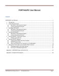
7
Title
Page
RSC-FORTH ASSEMBLER
7.1
7.2
The Assembly Process ................................
7-1
7.1.1
7.1.2
7.1.3
7-3
7-3
7-3
CODE Definitions .............................
Assembly-Time Versus Run-Time ................
CODE-Definition Example ......................
Assembler Op-codes ..................................
7-4
7.2.1
7.2.2
Single Mode Op-Codes .........................
Multi-Mode Op-Codes ..........................
7-5
7-6
7.3
Addressing Modes ....................................
7-5
7.4
R6502 Conventions ...................................
7-6
7.4.1
7.4.2
Stack Addressing .............................
Return Stack .................................
7-6
7-7
FORTH Registers .....................................
7-8
7.5
7.5.1
7.5.2
7.5.3
7.5.4
7.5.5
7.6
Assembly Registers ...........................
CPU Registers ................................
XSAVE ........................................
N Area .......................................
SETUP ........................................
7-8
7-9
7-9
7-9
7-10
Control Flow ........................................
7-10
7.6.1
7.6.2
7.6.3
7.6.4
7-11
7-12
7-13
7-14
Conditional Looping ..........................
Conditional Execution ........................
Conditional Nesting ..........................
Some Nesting Examples ........................
7.7
Return of Control ...................................
7-17
7.8
Assembler Security ..................................
7-18
7.8.1
7.8.2
Assembler Tests ..............................
Bypassing Security ...........................
7-18
7-18
Adding Assembly Code to Defining Word ...............
7-19
7.9
vii
TABLE OF CONTENTS
Section
8
Title
Handling Interrupts in FORTH
8.1
Types of Interrupt Handlers .........................
8-1
8.2
Machine Level Interrupt Handling ....................
8-1
8.2.1
8.2.2
CODE-Definition Form .........................
Code Fragment Form ...........................
8-5
8-5
Interpretive Interrupt Handling .....................
8-6
8.3
8.3.1
8.3.2
8.3.3
8.3.4
9
11
Interrupt Service Subroutine .................
Interrupt Processing Word ....................
Example ......................................
Points to Remember ...........................
9.1
Parallel I/O ........................................
9-1
9.2
Serial I/O ..........................................
9-9
9.3
Counter Timers ......................................
9-11
Counter A ....................................
Counters .....................................
9-11
9-16
Notes on Style and Program Development
10.1 General .............................................
10-1
10.2 Example Program .....................................
10-1
Preparing an Application Program for PROM Installation ...
11.1 Program Development .................................
12
8-6
8-6
8-7
8-8
Programming the R65F11 I/O in FORTH
9.3.1
9.3.2
10
Page
Interfacing to Mass Storage ..............................
12.1 Overview ............................................
12.1.1
12.1.2
11-1
11-1
12-1
12-1
Mass Storage Terminology ....................
Buffer Variables ............................
12-1
12-3
12.2 Setting up Block and Data Buffers ...................
12-3
viii
TABLE OF CONTENTS
Section
Title
Page
12.3 Using Mass Storage ..................................
12.3.1
12.3.2
12-5
Data Storage and Retrieval-the Virtual RAM ..
Program Loading and Overlays ................
12-5
12-6
12.4 Source Code Editings ................................
12-7
APPENDIX
APPENDIX
APPENDIX
APPENDIX
APPENDIX
A
B
C
D
E
APPENDIX
APPENDIX
APPENDIX
APPENDIX
APPENDIX
APPENDIX
APPENDIX
APPENDIX
APPENDIX
F
G
H
I
J
K
L
M
N
APPENDIX
APPENDIX
0
P
RSC-FORTH Functional Summary ....................
RSC-FORTH Glossary ..............................
RSC-FORTH Assembler Functional Summary ..........
RSC-FORTH Assembler Glossary ....................
Error Messages and Recovery .....................
E.l Standard Error Message .....................
E.2 Standard Error Message Word ................
E.3 RSC-FORTH Error Definitions ................
E.4 Disk Errors ................................
Page Zero Memory Map ............................
USER Variables RAM Map ..........................
ASCII Character Set .............................
FORTH String Words ..............................
USER 24-Hour Clock Program in FORTH .............
Utility Examples ................................
RSC-FORTH Versus FIG-FORTH ......................
RSC-FORTH Floppy Disk Interface .................
RSC-FORTH Screen Numbers Versus Track
Numbers .........................................
Editor ..........................................
Selected Bibliography ...........................
ix
A-l
B-l
C-l
D-l
E-l
E-1
E-2
E-2
E-6
F-l
G-l
H-l
I-1
J-l
K-l
L-l
M-l
N-l
0-1
P-l
LIST OF FIGURES
Figure
2-1
2-2
2-3
4-1
4-2
7-1
8-1
8-2
8-3
9-1
9-2
9-3
9-4
9-5
9-6
9-7
9-8
9-9
J-l
J-2
Title
Page
RSC-FORTH Memory Map ..............................
Typical RS65F11 Microcomputer Minimum Hookup
with R65FR1 Development ROM .....................
Auto-Start ROM Code Example .......................
VLIST of RSC-FORTH Words ..........................
Stack Diagram of Postfix Example ..................
VLIST of RSC-FORTH Assembler Words ................
Machine Level NMI Interrupt Handling ..............
Machine Level IRQ Interrupt Handling ..............
Interpretive Interrupt Handling ...................
R65F11 and R65F12 Interface Diagram ...............
Register Bit Assignments ..........................
RES Initialization of I/O Ports and Registers .....
Serial Communication Bit Allocations ..............
Interval Timer Timing Diagram .....................
Event Counter Mode ................................
Pulse Width Measurement ...........................
Counter B Retriggerable Interval Timer Mode .......
Counter B Pulse Generation ........................
24-Hour Clock Program Using a Machine Level
Interrupt Handler ...............................
24-Hour Clock Program Using an Interpretive
Interrupt Handler ...............................
x
2-3
2-4
2-6
4-2
4-9
7-2
8-2
8-3
8-4
9-2
9-4
9-6
9-10
9-13
9-15
9-15
9-18
9-18
J-3
J-4
RSC-FORTH ERRATA
RSC-FORTH V1.5
The RSC-FORTH Version 1.5 (V1.5) described in this manual is contained in
the following parts:
R65F11 FORTH Microcomputer
(R1100-11 or R1100-14, 1 MHz)
or
R65F12 FORTH Microcomputer
(R1200-11, 1MHz)
and
R65FR1 Development ROM
(R2952-12, 1MHz)
Errors in this version can be corrected as follows:
1. ADMP leaves two undefined bytes on the stack.
Redefine the word as:
: ADMP ADMP 2DROP ;
2. FORMAT is inoperative.
Redefine the word as:
: FORMAT 2 * SWAP 0 DO DUP 1+ SELECT I SEEK 1 I FMTRK DUP
SELECT 0 I FMTRK LOOP DROP ;
3. IRQVEC returns the value for INTVEC .
Redefine the word as:
HEX
: IRQVEC 0040 ;
4. I contains a reference to the Development ROM and can not be used
in stand-alone code.
Solution is to use R instead.
5. NOT contains a reference to the Development ROM and can not be
used in stand-alone code.
Solution is to use 0= instead.
6. CREATE has an error which can cause the CFA of a word to straddle
a page boundary, which is an error condition for the 6502 CPU.
Solution is to test a suspected word with:
HEX ' NAME CFA .
and verify that the address is not "XXFF". If the address is
"XXFF" the word should be forgotten and a "1 ALLOT" inserted
before redefining the word.
xi
RSC-FORTH V1.6
RSC-FORTH V1.6 corrects the ADMP and FORMAT errors mentioned above in
V1.5. RSC-FORTH V1.6 is implemented in ROM devices for use with either the
R6501Q or R6511Q ROM-less microcomputer. The R65FK3 is the Kernel ROM that
operates in conjunction with the R6501Q or R6511Q and functions like the
R65F11 or R65F12 FORTH microcomputer (with internal ROM). The R65FR3
Development ROM operates with the R6501Q/R6511Q microcomputer and R65FK3
Kernel ROM in a similar manner as the R65FR1 Development ROM operates with
the R65F11/R65F12 FORTH Microcomputer. These parts are identified as:
R65FK3 Kernel ROM
(R327H-11, 1 or 2 MHz)
and
R65FR3 Development ROM (R2953-11, 1 or 2 MHz)
RSC-FORTH V1.7
RSC-FORTH V1.7 corrects all the errors mentioned above in V1.5.
RSC-FORTH V1.7 is implemented in the following parts:
R65F11 FORTH Microcomputer (R1100-15, 1 MHz or R1100-16, 2 MHz)
or
R65F12 FORTH Microcomputer (R1200-13, 1 MHz or R1200-14, 2 MHz)
and
R65FR1 Development ROM (R2952-13, 1 or 2 MHz)
xii
SECTION 1
INTRODUCTION
FORTH is a unique programming system that is well suited to a variety of
applications. Because it was originally developed for real-time control
applications, FORTH has features that make it ideal for machine and process
control, data acquisition, energy and environmental management, automatic
testing, and other similar applications. The speed performance of assembly
language is required in many of these applications, however a high-level
language is often desired to improve program development productivity and
program reliability. FORTH is designed to satisfy both speed and programming
efficiency requirements.
FORTH can be called a computer language, an operating system, an interactive
compiler, a data structure, or an interpreter, depending upon your point of
view. It was designed to combine the strengths of both compilers and
interpreters. The result is a unique language based on pre-defined operations
that minimizes software development time and costs, supports structured
programming and program modularity, compiles interactively to ease debugging and
to reduce programming errors, compacts into small object code, and executes
extremely fast. Additional words may be defined to allow usage by
non-programmers.
When all of the features of the FORTH language are combined with the utility
of the RSC-FORTH single-chip microcomputer hardware, the result is a powerful
tool for the dedicated computer system designer. Many extensions have been added
to RSC-FORTH that allow a very low cost, few chip system to be both the
development system and the final target system.
1.1 RSC-FORTH USER'S MANUAL DESCRIPTION
This manual is designed to provide both introductory instruction and detail
language reference information. If you are new to FORTH, be sure to read and
follow the manual chapter-by-chapter using a system which includes the R65F11 or
R65F12 microcomputer, and the R65FR1 FORTH Development ROM as a teaching
aid in order to learn the FORTH language and operation concepts. If you
already know the FORTH language you can probably skip certain sections and
still use the language, however it is recommended to review all sections to
become familiar with the RSC-FORTH mechanization and unique features.
Section 1, Introduction, introduces the RSC-FORTH language and the RSC-FORTH
User's Manual.
Section 2, Functional Description, explains the hardware of the RSC-FORTH system
and how a RSC-FORTH system can be constructed.
Section 3, FORTH Concepts, provides a general overview into FORTH concepts and
advantages. This is a good chapter to read if you are new to FORTH.
Section 4, Elementary Operations, leads you through elementary and common
FORTH operations. By following this section step-by-step you will learn how
FORTH operates to a sufficient level to implement simple applications in FORTH.
1-1
Section 5, Advanced Operations, takes you into more complex FORTH operations
once you have become familiar with the elementary FORTH operations described
in Section 4.
Section 6, Special Operations, details the unique features of RSC-FORTH, not
found in other FORTH systems, designed to ease development in a single-chip
microcomputer system.
Section 7, RSC-FORTH Assembler, describes concepts and operating procedures
associated with the RSC-FORTH Assembler.
Section 8, Handling Interrupts in FORTH, explains how to use machine level and
interpretive interrupts in FORTH.
Section 9, Programming the R65F11 I/O, explains how to use FORTH to program
the R65F11 input/output section. These techniques can be used directly with
the R6511 and can easily be applied to other peripheral devices.
Section 10, Notes on Style and Program Development, discusses the general
approach to programming in FORTH and provides an example program.
Section 11, Preparing an Application Program for PROM Installation, tells how to
structure and locate a FORTH application program in a PROM which will operate in
conjunction with the R65F11 and R65F12 FORTH-based microcomputers.
Section 12, Interfacing to Mass Storage, tells how to prepare programs to
store and retrieve program and data from mass storage. Blocks, screens, and
buffers are described. The technique to handle program overlays is also
explained.
Appendix A, RSC-FORTH Functional Summary, summarizes FORTH word operation by
general area of usage.
Appendix B, RSC-FORTH Glossary, defines each FORTH word in ASCII sort order.
Appendix C, RSC-FORTH Assembler Functional Summary, summarizes FORTH assembler
word operation by area of usage.
Appendix D, RSC-FORTH Assembler Glossary, defines each FORTH Assembler word in
ASCII sort order.
Appendix E, Error Messages and Recovery, identifies each FORTH error number
and/or message, defines the error meaning, and describes the recovery action.
Appendix F, Page Zero Memory Map, defines the address, variable name and general
usage of page zero parameters.
Appendix G, User Variables RAM Map, defines the address, variable name and
purpose of each user variable. The cold and warm start initialization values are
also listed.
Appendix H, ASCII Character Set, provides a list of 7-bit ASCII codes in decimal
and hexadecimal corresponding to 32 control functions and the 96 upper and lower
case alphabetic, numeric and special characters.
1-2
Appendix I, FORTH String Handling Words, describes how to create string handling
functions in FORTH.
Appendix J, User 24-Hour Clock Program in FORTH, illustrates a program written
in FORTH colon- and CODE-definitions, i.e., FORTH high-level words and 6500
assembly language.
Appendix K, Utility Functions, explains how to determine the time it takes for a
FORTH word to execute.
Appendix L, RSC-FORTH Versus FIG-FORTH, identifies words incorporated in each
FORTH that are not included in the other FORTH.
Appendix M, Selected Bibliography, lists references to many popular and tutorial
FORTH articles and books.
1.2 REFERENCE DOCUMENTS
Rockwell
29650N30
Order No. 202
R6500 Programming Manual
29650N31
Order No. 201
R6500 Hardware Manual
29651N49
Order No. 2146
R65F11 and R65F12 FORTH Based
Microcomputer Product Description
29651N59
Order No. 2156
RSC-FORTH Reference Card
29651N65
Order No. 2162
Application Note; A Low-cost
Development Module for the
R65F11 FORTH Microcomputer
1-3
This page is intentionally left blank.
1-4
SECTION 2
FUNCTIONAL DESCRIPTION
The RSC-FORTH system integrates a complete ROM-based FORTH system consisting of
microprocessor, memory and peripheral hardware elements and RSC-FORTH software
into a single-chip microcomputer for runtime applications and a two-chip set for
application software development. The RSC-FORTH software includes a Software
Kernel, comprised of an RSC-FORTH Operating System and runtime portions of the
RSC-FORTH language, which is masked into ROM in the one-chip microcomputer. Two
versions of this microcomputer are available: the R65F11 and R65F12. Each
version has the same Software Kernel but different input/output capabilities.
The other portions of the RSC-FORTH software, not required at runtime, are
provided in a separate and supporting R65FR1 Development ROM for use during
application program development. The hardware elements of the microcomputer and
the features of the operating system are presented first so the interaction with
the runtime and development portions of the RSC-FORTH language can be fully
understood.
2.1 RSC-FORTH HARDWARE
2.1.1 R65F11 and R65F12 Microcomputers
The Rockwell R65F11 and R65F12 are complete, high-performance, 8-bit NMOS single
chip microcomputers, and are compatible with all members of the R6500 family .
The R65F11 and R65F12 consist of an enhanced R6502 CPU, an internal clock
oscillator, 3K-bytes of masked Read-Only Memory (ROM), 192 bytes of Random
Access Memory (RAM), and versatile interface circuitry. The interface circuitry
includes two 16-bit programmable timer/counters, 16 bi-directional input/output
lines (including four edge-sensitive lines and input latching on one 8-bit
port), a full-duplex serial I/O channel, ten interrupts and bus expandability .
The innovative architecture and the demonstrated high performance of the R6502
CPU, as well as instruction simplicity, results in system cost-effectiveness and
a wide range of computational power. These features in combination with the RSCFORTH high level operating system make the R65F11 and R65F12 ideal for
microcomputer applications.
The R65F11, with its two 8-bit ports, is housed in a 40-pin DIP. For systems
requiring additional I/O ports, the 64-pin QUIP version, the R65F12, provides
three additional 8-bit ports.
The kernel of the high level Rockwell Single Chip FORTH (RSC-FORTH) language is
contained in the preprogrammed ROM of the R65F11 and R65F12. RSC-FORTH is based
on the popular fig-FORTH model with extensions. All of the runtime functions of
RSC-FORTH are contained in the ROM, including 16- and 32-bit mathematical,
logical and stack manipulation, plus memory and input/output operators. The
RSC-FORTH Operating System allows an external user program
2-1
written in RSC-FORTH or Assembly Language to be executed from external EPROM, or
development of such a program under the control of the R65FR1 RSC-FORTH
Development ROM.
2.1.2 Configuring an R65Fll/R65F12-Based System
There are several ways to configure an R65F11 or R65F12-based system. A minimum
system includes the R65F11 or R65F12 microcomputer, a crystal, application
program in PROM/ROM and application input/output interface. Such a system can
be expanded in memory up to the 16K address limit of the R65F11/R65F12. The
R65F1 Development ROM may be included in any RSC-FORTH system by providing
proper decoding logic.
There are two basic configurations of RSC-FORTH based systems:
a.
Using an R65F11. An external addressing space of 16K bytes is possible
with the use of an eight-bit latch. The R65FR1 (at address $2000-$3FFF)
may be used as a development ROM. Two I/O Ports (A & B) are available to
the user.
b.
Using an R65F12. Five I/O ports (A, B, E, F and G) are available to the
user. All other comments are the same as for the R65F11.
Additional ROM, RAM and I/O devices can be added to the external memory map as
desired. Figure 2-1 shows a RSC-FORTH memory map. Figure 2-2 shows a typical
maximum electrical hook-up for an R65F11 system with and R65FR1 Development ROM
and RS-232C serial interface for connection to a CRT/keyboard terminal. Wiring
for an R65F12 system would be almost identical.
2.2 RSC-FORTH SOFTWARE
2.2.1 Operating System
Much of the philosophy needed to build a RSC-FORTH microcomputer system can be
understood by looking at the RSC-FORTH operating system.
Many cost effective, eight-bit memory devices are available to the system
designer today. These ROMs, RAMs, EPROMs and EEROMs usually come in multiples of
1K-byte increments. The most popular are the 2K-byte versions such as the 2016,
6116 and similar RAM devices and the 2716 type EPROMs. The RSC-FORTH Operating
System is designed to work with these memory products.
The purpose of an operating system is to initiate operation in an orderly manner
during power on or reset, the (loading and) starting of user functions and
allocation of system resources. The RSC-FORTH Operating System provides these
and many other services. Since the RSC-FORTH system is designed to serve in a
dedicated application, the operating system's unique power up procedures are
most interesting.
Upon reset, the reset vector in the kernel ROM directs processor execution to a
section of machine code in the FORTH word COLD . This initializes the
microcomputer for operation. Register values are established and interrupt
sources disabled. The serial channel of the microcomputer is set up for 1200
2-2
baud asynchronous transmission (assuming a 1 MHz internal clock) with seven data
bits, no parity, and two stop bits. System variables including pointers that
make the serial channel the system method of input/output are down-loaded from
ROM to zero page in RAM for read/write operation.
A test is made to determine the reset status. If a user variable, CLD/WRM , in
memory location $030E, contains a value other than $A55A, a cold reset is
assumed. In this case, the low level IRQ vector (IRQVEC), the low level NMI
vector (NMIVEC), and the high level interrupt vector (INTVEC) are forced to
point to the system reset routine. This prevents an unintentionally generated
interrupt from crashing the system. System variables TIB , RO , SO ,
UC/L , UPAD , UR/W and BASE are also initialized to their default values. If a
warm start is detected, only TIB , RO and SO are reset to default values (The
meanings of these variables are described in Appendix A).
2.2.2 Application Program Auto-Start
Whether a warm or cold reset, the memory map is then examined at every 1K-byte
boundary starting at location $0400, i.e. $0400, $0500, $0600, etc., through
$3F00. The first two bytes at each boundary are compared to an $A55A bit
pattern. This pattern indicates an auto-start ROM is installed. If the autostart pattern is present, the next two bytes must point to the Parameter Field
of a high level RSC-FORTH word to be executed upon reset. Assembly language
routines can also be autostarted by using a series of indirect pointers.
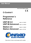
Details on auto-start ROM patterns are shown in Figure 2-3.
2.2.3 Development ROM Startup
The R65FR1 Development ROM is an example of an auto-start ROM. If there is no
other auto-start pattern lower in the memory map, when the operating system
finds the R65FR1 Development ROM, the familiar start up of the RSC-FORTH will
occur and the message
RSC-FORTH VI.5
is displayed.
FORTH words can now be entered interactively (see Section 3.1).
2.2.4 Bootstrap Program Load
If no development ROM is found, the message "NO ROM" is issued by the operating
system. Providing no interruption from the operator at that point, the RSC-FORTH
System attempts to load a bootstrap program from floppy disk. The first 128
bytes of Track 0 Sector 1 is loaded into RAM starting at address $005F. After
loading, execution is turned over to the boot program at $005F.
The boot program can be any machine code program that will fit in 128 bytes.
Clever programmers will even be able to restart FORTH (since it was a FORTH word
that called the boot) and execute a high level boot.
2.2.5 Micro Monitor
When the system issues the "NO ROM" message, before actually calling the boot
program, the serial input channel is checked for a CNTL R character ($12).
Normally, as the microcomputer powers up, the contents of the serial input
2-5
Figure 2-3. Auto-Start ROM Code Example
register will be some other value, thus boot from floppy disk will be initiated.
If a CNTL R key combination is received from the serial input channel then RESET
pressed, a program called the "Micro Monitor" is entered. The Micro Monitor is
completely self-contained in the kernel. The microcomputer with the kernel
requires only RAM from address $0300 through $3FF to run the Micro Monitor. The
external RAM is required for FORTH user variables, PAD and the Terminal Input
Buffer (TIB).
The Micro Monitor outputs a "greater than" sign, ">", to the system terminal at
the beginning of a new line then waits for an input line from the operator. The
Micro Monitor is actually a very simple FORTH interpreter. Much like the full
FORTH interpreter, the Micro Monitor allows the operator to enter FORTH words to
be executed and numbers to be placed on the stack. Since it is stand alone and
operates without the aid of a development ROM, FORTH words must be referenced by
their Parameter Field Addresses, rather than their name. The way words and
numbers are distinguished by the Micro Monitor is by the first character in the
input stream on the line. If that character is an "N", it is processed as a
number and placed on the data stack. If the character is a "W", the entry is
considered to be a FORTH word which is immediately executed. The characters
following the first character must be hex digits. The line entry is terminated
with a carriage return. Only one entry, i.e., number or FORTH word, can be made
per line.
Entry into the Micro Monitor can also be gained by executing the FORTH word MON
from the R65FR1 Development ROM. As an example of the use of Micro Monitor, the
following sequence shows the entry of two numbers, their addition, and the
outputting of the results. The Micro Monitor was entered by either sending CNTL
R then pressing RESET without an auto-start ROM in the system, or by commanding
MON in the development system.
2-6
>N1111
(The > indicates the Micro Monitor is ready )
(for input. The N1111 entered by the operator)
(puts a $1111 on the data stack.
)
>N222
(The Micro Monitor returns the > after the
(last command is finished. The operator
(enters the second number, $0222.
)
)
)
>WF778
(The W entered by the operator indicates the
(following number is a FORTH word to be exe(cuted. The address $F778 is the Parameter
(Field Address of the FORTH word + . The
(Micro Monitor causes the two numbers to be
(added therefore and the result left on the
(stack.
)
)
)
)
)
)
)
>WFEE4 1333
(The operator enters another FORTH word to
)
(be executed. This one is the . command
)
(which outputs the top value from the data
)
(stack. The outputted result is displayed
)
(on the same line. After command completion )
(the Micro Monitor displays the > , to
)
(indicate that it is ready for another input.)
A list of all the available FORTH words available in the kernel with their
Parameter Field Addresses are listed in Table 2-1. There are many useful words
that can be accessed by the user with the Micro Monitor. It is possible to
examine I/O ports, load programs from disk and even program EPROMs under
direction of the Micro Monitor. It should be easy to imagine many uses for the
Micro Monitor when making field modifications to existing products based on RSCFORTH.
2-7
Table 2-1. RSC-FORTH Kernel Words with their
Parameter Field Addresses
_________________________________________________________________
*!
F858*2DUP
F7EF*D+FC42*MOD
FCD4*
*#
FE7D*3
F8BB*D.
FECE*NEGATE
F7A5*
*#>
FE5C*4
F8BF*D.R
FEB0*OR
F6CE*
*#S
FEA0*;S
F717*DABS
FC56*OVER
F7C5*
*(+LOOP)
F4D0*<
F954*DECIMAL
F9BC*PAD
F8F0*
*(.")
FA31*<#
FE52*DIGIT
F50D*PICK
F98F*
*(DO)
F4F8*=
F938*DISK
FD08*QUERY
FAAC*
*(FIND)
F535*>
F96C*DNEGATE
F7B5*R
F73F*
*(LOOP)
F4AF*>R
F734*DPL
F8E2*R>
F73F*
*<NUMBER)
FB06*?
FEEC*DREAD
F056*RP!
F6FD*
**
FCB6*?TERMINAL
F60A*DROP
F7CF*RP@
F80C*
**/
FCE8*@
F83B*DUP
F7E5*R0
F8CD*
**/MOD
FCDC*ABS
FC4E*DWRITE
FDBE*ROT
F974*
*+
F778*AND
F6BE*EEC!
FEF4*S->D
FC2C*
*+!
F818*BANKC!
FF42*EMIT
F5D4*S0
F8CA*
*+FC36*BANKC@
FF4A*ENCLOSE
F591*SEEK
FE11*
*F96C*BANKEEC!
FF52*ERASE
FAE4*SELECT
FD43*
*-DUP
F9A5*BANKEXECUTE FF5A*EXECUTE
F471*SIGN
FE6C*
*-TRAILING
FA0B*BASE
F8D9*EXPECT
FA45*SP!
F6F3*
*.
FEE4*BL
F8C3*FILL
FABE*SP@
F6EA*
*.R
FED8*BLANKS
FAEC*HEX
F9B1*SPACE
F99D*
*/
FCCA*BOUNDS
F803*HLD
F8E5*SPACES
FE3A*
*/MOD
FCBE*BRANCH
F480*HOLD
FAF4*SWAP
F7D3*
*0
F8AF*C!
F868*IN
F8DF*TIB
F8C7*
*0<
F76B*C/L
F8E8*INIT
FDF1*TOGGLE
F830*
*0=
F7A5*C@
F84B*KEY
F5F6*TYPE
F93F*
*0BRANCH
F497*CLD/WRM
F8DC*LEAVE
F722*U*
F646*
*1
F8B3*CLIT
F458*LIT
F40E*U/
F67B*
*1+
F8F8*CMOVE
F626*M*
FC7E*U<
F940*
*1F913*COLD
FB48*M/
FC94*UC/L
F8D0*
*2
F8B7*COUNT
F9E3*M/MOD
FCF2*UPAD
F8D3*
*2+
F820*CR
F613*MAX
FC6E*UR/W
F8D6*
*2F920*D+
F787*MIN
FC5E*XOR
F6DC*
*2DROP
F7D1*
*
*
*
2-8
SECTION 3
FORTH CONCEPTS
FORTH is quite different from more conventional languages such as BASIC,
FORTRAN, or Pascal. It creates a computing environment with unique strengths,
tools, and styles. Some of the structures of FORTH have little correspondence
with those of other languages. This overview of the language and the RSC-FORTH
implementation provides background for the how-to-do-it chapters which follow.
3.1 FEATURES OF FORTH
FORTH is EXTENSIBLE, meaning that you add your own operations to the language.
New words (operations) are defined in terms of previously defined words (or
assembly language), until a single word represents the entire user's program.
The program word can then be executed by typing its name or made to auto-start
upon reset. Except that your words may be defined in RAM, (or user provided PROM
or ROM), there is no distinction between your new operations and those
originally part of the language. Extensibility allows users to define libraries
or even their own languages for particular applications-, greatly facilitating
maintenance as requirements change.
FORTH keeps all definitions in a DICTIONARY. The dictionary includes virtually
all the object code of the system itself and of your applications. Your own data
structures may be in the dictionary or outside it, at your option. The internal
structure of the dictionary is uniform and much simpler than the internals of
most other languages; therefore, application programmers typically learn much
more of the inner workings of the FORTH system.
Compiled FORTH code is extremely COMPACT in memory, even compared to machine
language. The overhead associated with most FORTH systems is nearly non-existent
in RSC-FORTH. Since the runtime portions of RSC-FORTH are in internal ROM,
there is no kernel to add to the user's code. RSC-FORTH can target compile user
code and remove all the overhead of the dictionary structures. By referring to
the internal runtime kernel and user defined function, RSC-FORTH's hierarchical
structure allows application code to build on itself, increasing the memory
advantage for larger programs, and with little loss in speed.
FORTH code is recursive, suited to multi-tasking applications, and can be
programmed in RAM, PROM or ROM.
FORTH is STRUCTURED. There is no GOTO statement in the language. IF and ELSE
control structures, and DO, UNTIL, and WHILE loops are provided; all of these
can be nested to any practical depth.
FORTH uses a STACK and its associated POSTFIX NOTATION, also called Reverse
Polish Notation (RPN), in which the operation codes are written after the
operands which they use. For example, <2+2> in BASIC would be written <2 2 +> in
FORTH. Why does FORTH use a stack explicitly when most other languages hide
their stacks from the user and avoid postfix in favor of more conventional
notation?
3-1
Part of the answer is that the stack allows very low overhead for linking
between subroutines. FORTH reduces the cost of subroutines to very little, and
the whole language is built around subroutine calls. Routines can accept and
return any number of arguments, without the complexity or other overhead of
formal parameter or local variable declarations.
The stack encourages extremely MODULAR programming, which can be debugged with
great reliability. Consider FORTH's programming environment. Each module (i.e.,
word or procedure) has only one entry and one exit point. Usually all
communication with the outside world is through the stack, so there are no side
effects on other modules, variables, etc., unless explicitly programmed. Usually
each module is short; commonly three to five lines. The smaller a module is, the
easier it is to test all paths through it.
FORTH is INTERACTIVE. Testing is immediate, because almost all FORTH words can
be executed directly as commands from the keyboard, and will behave exactly the
same in this mode as when compiled into later definitions. Any arguments
required can simply be typed onto the stack before the test, or generated by
other operations, and results can be observed or printed immediately. Usually
each component of the new definition can also be executed interactively from the
keyboard, to aid in debugging.
FORTH debugging seldom requires examining any code except the single definition
being tested. Documentation of the behavior of the defined words in glossary
form is required, i.e., inputs, outputs, and actions, but there is no need for
their code to be listed. Fewer listings are therefore required during FORTH
program development than with other languages. Everything you need to work with
is directly in front of you.
FORTH allows easy MACHINE ACCESS, unlike most other high-level languages. All of
memory and-I/O (data ports and control registers) can be addressed, although
run-time protection can be implemented simply by redefining appropriate system
or user words to include run-time bounds or other checks during testing. Except
for direct access to machine-specific registers (A, X, Y, etc. in the R6502 CPU)
which require assembly language subroutines, FORTH can do anything machine
language can do. And FORTH runs fast enough that usually no assembly language
subroutines are necessary.
But if full machine speed is needed, RSC-FORTH includes an assembler. It also
allows machine language subroutines to be tested immediately as soon as the
assembly source has been typed in or otherwise entered, with no waiting for
separate assembly and linking passes. It encourages structured programming even
in assembly language; IF...ELSE and BEGIN...UNTIL macros are provided. Users can
define their own macros, and use the full power of FORTH for address arithmetic
and other assembly-time utilities. All R6502 and R6511Q op codes and addressing
modes are available. This one-pass assembler is implemented in about 1.5K bytes,
illustrating the compactness of FORTH's object code.
The routines created by this assembler have FORTH names and behave exactly like
regular FORTH definitions. The user needn't know which words are programmed in
assembly language. Therefore, an application can first be written entirely in
high level using FORTH words, and, if more speed is necessary, parts can be
converted to assembly language code with no changes required elsewhere.
3-2
FORTH code is extremely TRANSPORTABLE between machines. It is common for
substantial programs to be moved between different computers such as 6502, 8080,
and PDP-11 with very little change or none at all. The RSC-FORTH system follows
the FORTH Interest Group (FIG) language model, probably the most common dialect
of FORTH, and one closely aligned with the International Standard for the
language. The FIG model is available on the common small computers and is
rapidly being implemented on others. Therefore the R65F11/R65F12 microcomputer
in conjunction with the R65FR1 Development ROM can be used to develop software
for other computers, and it can use published FIG-model code regardless of the
machine on which it was developed. Published programs are commonly written
entirely in FORTH with no machine code or other dependencies, but designed so
that short, time critical words can be rewritten in assembly language for
optimization on any particular host machine. These programs can first be run
unchanged, then optimized only if needed.
As in any programming, good style makes the application program easier to debug
and verify, and easier to read and modify when requirements change. Many
recommended FORTH practices are familiar from other language environments, but
some are different. Practices such as top-down design and bottom-up coding and
testing, short modules, indentation of control structures, and a glossary as the
principal documentation during development, are discussed throughout this
manual.
3.2 DEBUGGING
The FORTH environment's convenient and powerful debugging and error control
features are an important advantage of the system. FORTH allows complete access
to the machine, without the restrictions of many other languages such as BASIC
and Pascal which try to guard the programmer against mistakes. Most users report
that FORTH allows them to quickly produce and modify programs which are
exceptionally reliable.
Although RSC-FORTH includes extensive compile-time checking which detects most
of the detectable errors (see Appendix E), the most important error control is
in the tools which the FORTH environment itself gives to the programmer.
Like most other modern languages, FORTH encourages "structured programming"
design techniques, which helps to control errors. FORTH is extremely modular,
even compared to other structured languages; each software module can be tested
and debugged independently. Usually all communication between a module and the
outside world is through an internal stack. Each module relies on earlier
modules which have already been debugged, and in turn, the new testing helps
catch any errors that may still be hidden in the earlier work.
Testing is immediate and interactive; simply type arguments onto the stack,
execute the word, and output the results. If more elaborate test data is
needed, a special word can generate it. This ease of testing means that a large
number of tests can be run quickly.
Each module should be short, in the programming style preferred by most FORTH
users, so that all possible paths of control can be tested easily.
3-3
If correct results are not obtained, it is possible to step through the
definition by executing each component word individually, checking the stack
whenever desired. RSC-FORTH has a special word, .S , which non-destructively
prints the stack contents to help in this kind of debugging. Any unexpected
results can be localized to a particular component word, which in turn can then
be examined in detail. Because FORTH words work identically when compiled, or
when executed as commands, the programmer can debug at either a batch or
interactive operation mode.
Because FORTH is extensible, words can be re-defined to perform their original
functions and, in addition, give special debug print-outs or do run-time error
checks. These redefinitions can be inserted into programs for testing and
removed later; nothing else in the program need be changed.
RSC-FORTH also includes a memory dump and other words for examining or changing
memory. These commands can be compiled into programs or executed from the
keyboard.
In contrast to most other operating systems, all of these tools are part of the
normal FORTH environment. No special syntax or command language must be learned
for debugging.
Each FORTH word is documented by a glossary (see Appendix B) which lists the
arguments it takes from the stack and the results returned, and gives a short
verbal description (usually one to three sentences) of its action. Such a
glossary completely describes the word as it is seen by any other part of the
program. When a new word is being tested, all earlier words should have these
descriptions available. Therefore, the programmer seldom needs to look at the
source code of any other word; the glossary fully describes its functions.
During testing and debugging, only one word at a time needs to be examined —
this greatly cuts down the need for program listings during development.
One important debugging procedure applies only to FORTH. After a word appears to
work correctly it must be tested to make sure that it does not take any
unexpected numbers off the stack, or return unexpected results. One way to
check is to leave markers, easily-recognized numbers, such as 1, 2 and 3, on the
stack and then execute the word being debugged. After an operation, use .S to
make sure that the markers are still on the stack, below any arguments returned
by the test word. This check is important because otherwise the word may look
like it works, but causes later program crashes at unexpected and seemingly
random places making the problem hard to debug.
3-4
SECTION 4
ELEMENTARY OPERATIONS
This section provides a step-by-step description of elementary RSC-FORTH
operations, such as:
.
.
.
.
.
.
Performing simple arithmetic and comparisons
Entering and retrieving data from memory
Using the stack
Compiling interactively or in a batch mode from memory
Defining new FORTH words
Performing looping and conditional sequences
A major portion of FORTH is the FORTH dictionary itself. Each word in the FORTH
dictionary causes specific actions or operations to be performed. The use of
FORTH is explained primarily by describing how each word operates and how to use
it, either individually or with other words. Let's start by seeing what is in
the FORTH dictionary.
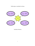
List the contents of the FORTH dictionary by running a VLIST . Type
VLIST
and then press the <RETURN> key. The entire FORTH dictionary will be displayed.
Terminate the listing at any time by pressing any key. The entire VLIST is shown
in Figure 4-1. Note that the words do not appear to be in any general order; the
words are listed by their address in the R65FR1 Development ROM. (The FORTH
dictionary structure is explained in detail in Section 5.5, but leave that for
later.) These FORTH words are described in ASCII sort order for convenient
lookup in the glossary in Appendix B and summarized by associated function in
Appendix A.
RSC-FORTH may be readily learned by performing the following procedure. As each
new FORTH word is encountered in this section, read the explanation and perform
the accompanying examples. Then read the word definition in the Appendix B
glossary. Repeat the examples, but vary one or more of the parameters until you
thoroughly understand the operation of the described FORTH word.
As you are learning FORTH, you may make errors that either cause an error
message to be displayed or cause the microcomputer to hang up or to run away. If
an error occurs with a displayed error message or number, refer to Appendix E
for the error definition and suggested recovery. If the program appears to hang
up or run away, press the <RESET> key to reinitialize the microcomputer. You can
then try the example again. You may have to back up a few steps, however, to
recover the example initialization.
4-1
VLIST
40B
367E
364C
35ED
35B6
3584
3554
3518
345B
3391
3375
3358
3301
32A9
3257
3149
306E
304B
3017
2F99
2ED7
2DBF
2D38
2D15
2CF9
2CD9
2CB9
2BF9
2B7D
2AB2
298B
28E6
2877
2836
27E6
2795
2753
26F8
269B
2646
25F7
25D3
25BA
2575
2524
2507
24D4
24A7
2471
243B
2402
TASK
FMTRK
BANKC!
SCDR
IER
PE
PA
INTFLG
VLIST
.
#S
<#
IF
UNTIL
THEN
AUTOSTART
‘
DREAD
B/SCR
LOAD
(LINE)
BUFFER
M/MOD
/
M*
ABS
COLD
DEFINITIONS
IMMEDIATE
LITERAL
ERROR
(NUMBER)
ERASE
EXPECT
TYPE
;CODE
SMUDGE
?CSP
? ERROR
CFA
-DUP
>
HERE
DP/
1+
C/L
STATE
BLK
VOC-LINK
WARNING
3844
3674
3641
35DF
35A9
3578
3548
34EF
33EC
338B
336E
3351
32E8
3291
323A
3110
3068
3041
3009
2F40
2E94
2D9A
2D2E
2D0F
2CF2
2CD1
2C4C
2BE1
2B2D
2A94
2977
2894
286D
2804
27DD
277D
273D
26E4
2686
263C
25EE
25CD
25A8
2560
251C
2500
24C9
249A
2466
242B
23F3
ADMP
BANKEXECUTE
EEC!
SCSR
IFR
PD
NMIVEC
C,CON
INDEX
.R
1
SPACES
REPEAT
+LOOP
ENDIF
?KERNEL
SEEK
SELECT
B/BUF
MESSAGE
DUMP
EMPTY-BUFFERS
*/
/MOD
MAX
D+ABORT
ASSEMBLER
INTERPRET
[COMPILE]
(ABORT)
WORD
FILL
."
COUNT
(;CODE)
]
?PAIRS
!CSP
LFA
SPACE
<
C,
,/
2PAD
KHZ
CURRENT
PREV
HEADERLESS
WIDTH
Figure 4-1.
3805
3664
361E
35D1
359C
356C
3538
34AC
33A0
3384
3368
333E
32CF
3279
3226
30BC
305F
3036
2FED
2F0F
2E69
2D72
2D27
2D06
2CEA
2CC9
2C1D
2BCS
2B02
29F1
2949
288B
2846
27FD
27C1
2771
272D
26CC
2670
262A
25E4
25C7
2595
2551
2515
24F0
24BE
248B
245A
2419
23E6
;DUMP
BANKEEC!
CASE:
SCCR
PG
PC
IRQVEC
.S
LIST
D.
SIGN
WHILE
AGAIN
LOOP
BEGIN
HWORD
INIT
DISK
-BCD
>LINE
FLUSH
UPDATE
*/MOD
*
MIN
+QUIT
FORTH
?STACK
CREATE
-FIND
HOLD
(.")
DOES>
DECIMAL
[
?EXEC
PFAPTR
LATEST
PICK
U<
,
ALLOT/
1LIMIT
MODE
CONTEXT
USE
DP
OFFSET
VLIST of RSC-FORTH Words
4-2
37CF
3657
35FD
35C3
3590
3560
3528
349F
3397
337D
335F
331A
32BF
3264
3185
3086
3056
3023
2FC9
2EFB
2E09
2D41
2D1D
2D00
2CE2
2CC2
2C0B
2B97
2AE5
29C8
28F1
2882
2840
27F4
27AF
2765
2715
26B3
2656
2604
25DB
25C0
2587
253E
250E
24DE
24B2
247C
244F
240F
23D8
FORMAT
BANKC@
MEMTOP
MCR
PF
PB
INTVEC
MON
?
D.R
#>
ELSE
END
DO
FORGET
H/C
DWRITE
R/W
—->
.LINE
BLOCK
+BUF
MOD
M/
DABS
S->D
(
VOCABULARY
DLITERAL
ID.
NUMBER
BLANKS
QUERY
-TRAILING
<BUILDS
HEX
COMPILE
?COMP
NFA
TRAVERSE
ROT
=
ALLOT
HERE/
2+
FIRST
CSP
SCR
UABORT
FENCE
ULIMIT
23CA
2393
2370
234C
232F
2317
22BE
2268
224A
2227
2202
21DE
21C0
21A1
2181
2163
20E6
20B8
2090
2069
203B
UFIRST
HLD
BASE
R0
4
0
CONSTANT
!
+!
SWAP
DNEGATE
0<
R>
RP@
XOR
U*
XOFF
KEY
DIGIT
(LOOP)
CLIT
23BC
238B
2367
2345
2329
2303
22A3
2262
2243
221E
21F6
21D5
21B9
2199
2179
215C
20D5
20B0
2084
205E
2032
B/SIDE
DPL
UR/W
S0
3
USER
;
C@
BOUNDS
2DROP
NEGATE
NOT
>R
RP!
OR
CMOVE
XON
EMIT
I
0BRANCH
LIT
23AE
2383
235E
233E
2323
22EC
2285
225B
2238
2214
21EB
21CD
21B2
2191
2172
2145
20CD
20A7
207E
2052
OK
CYLINDER
IN
UPAD
TIB
2
CODE
:
@
2DUP
DROP
D+
0=
LEAVE
SP!
AND
FINIS
CR
ENCLOSE
(DO)
BRANCH
Figure 4-1. VLIST of RSC-FORTH Words (Cont'd)
4-3
239E
237C
2355
2336
231D
22D9
226F
2255
222F
220B
21E4
21C6
21A8
2189
216A
20F9
20C6
209B
2075
2047
DISKNO
CLD/WRM
UC/L
BL
1
VARIABLE
C!
TOGGLE
DUP
OVER
+
R
;S
SP@
U/
SOURCE
?TERMINAL
(FIND)
(+LOOP)
EXECUTE
In the following descriptions, a FORTH word comprising of letters and numbers is
written in upper case. Since some FORTH words contain special characters that
may be confused with sentence structure, e.g., periods, commas, or apostrophes,
the FORTH words are set off by spaces, e.g., .S . These single spaces are not
part of the FORTH word and should not be entered.
4.1 SIMPLE ARITHMETIC
FORTH arithmetic, like that of advanced pocket slide rule calculators, uses a
stack to store operands and results. Operations such as + - * / (add, subtract,
multiply, and divide) take their arguments from the stack, and return their
results to it.
To see how the stack works, give FORTH a cold restart by typing
COLD
and pressing the <RETURN> key. The system will display
RSC-FORTH VI.6
Now type the following five numbers
1
22
333
-44
5
and terminate the input by pressing the <RETURN> key. <RETURN> at the end of a
line signals that your input is complete. (The <RETURN> is shown in the initial
examples, but is not shown in later examples, except where needed to clarify
data or command entry.) Be sure to insert one or more spaces between each
number. Now the numbers 1 through 5 are separate numbers stored on the stack
with 5 at the top. FORTH responds to your input by displaying OK . OK means
that the system has correctly acted on your command and is waiting for another
command to be entered. (The OK is not shown in most of the examples, however,
it is implied in all operations.) After <RETURN> is pressed, the following is
displayed:
1 22 333 -44 5 OK
Notice that the cursor indicates the input character position. A typing error
during FORTH command or data entry can be corrected by pressing the <DEL>, key
<BACK SPACE> or <RUB OUT> on the terminal as necessary.
4.1.1 Examine Stack Contents with .S
The word .S (pronounced dot-s) may be used at any time to examine the contents
of the stack without altering the values or removing the numbers from the stack.
Try it by typing
.S <RETURN>
4-4
The numbers entered in the prior section will be displayed (in some examples the
displayed data is underlined to distinguish it from entered data)
5
-44
333
22
1 OK
The .S word is very useful when learning RSC-FORTH or debugging a FORTH program
to determine the stack contents immediately prior to and/or after executing a
FORTH word.
4.1.2 Print from the Stack using .
The print command removes a number from the stack and displays it (and prints it
if the printer is ON) in the current I/O number base. In FORTH, the print
command is represented by a period and is called "dot". Type
. <RETURN>
The 5 will be displayed and removed from the stack.
. 5 OK
Verify this by typing .S and <RETURN> to show the new contents of the stack.
-44
333
22
1 OK
The next dot (and <RETURN>) will print the -44. Multiple commands separated by
spaces, can be typed on one line like this
. . <RETURN>
to display two numbers from the stack, e.g.,
. . <RETURN> 333 22 OK
Now only 1 is left on the stack. Output it with
. <RETURN>
which displays
. 1 OK
Trying to examine or print the stack contents when there are no numbers on the
stack will result in an error message. Try .S which will show
.S <RETURN>
EMPTY OK
4-5
Note that the word . will now cause a stack underflow and will display an
indeterminate value along with a stack empty message. Try it now
. 0 (typical number)
. ? STACK EMPTY
Similar FORTH operations trying to pull a number from an empty stack will result
in this error message. This error message, as well as others, are described in
Appendix E.
Notice that the data was displayed on the same line as the commands, i.e., the
FORTH word . in this case. Many times it is desired to display and print data
on a new line. The FORTH word CR issues a carriage return to the terminal.
Repeat the previous examples but insert CR before the . word and note that the
numbers are displayed on separate lines. Also try CR after the . and observe
the results.
Perform a cold restart before continuing.
COLD
RSC-FORTH V1.6
4.1.3 Clearing the Stack
It is sometimes desirable to delete data from the stack without performing a
COLD restart. The stack may be cleared by trying to execute a word that is not
currently defined in the FORTH dictionary. This causes an error condition in
which FORTH echoes the missing word followed by a "?" (see Appendix E for error
descriptions) and then clears the stack. Initially, the word Q is not defined in
the FORTH dictionary and can be conveniently used to clear the stack.
Note also that entering a word that is not in the dictionary will also delete
data that you may want on the stack — so be careful with your word entries or
you may have to re-enter data or repeat prior steps.
Enter some numbers on the stack and display the stack contents.
678 356
.S
356
678 OK
Type Q now and verify that the stack is cleared.
Q
Q ? .S
EMPTY OK
4-6
4.1.4 Add + and Subtract Let's now perform some simple arithmetic. Put two numbers on the stack, say
12809 135 <RETURN>
Now type the add command
+ <RETURN>
The + takes whatever two numbers are on top of the stack and adds them.
removes those numbers (by convention, most FORTH operations destroy their
arguments on the stack), and replaces them with their sum. Type
It
. <RETURN>
to verify this. The sum will be displayed as
. 12944 OK
As before, multiple operations can be placed on one line, e.g.,
12809 135 + . <RETURN> 12944 OK
Subtract works in a similar manner. Try
12809 135 - . <RETURN> 12674 OK
Repeat these last two examples but, insert CR before and after the word to
display the result on a separate line.
4.1.5 Multiply * and Divide /
Multiply and divide also work in a similar manner. Try the following
38 78 * .
<RETURN> 2964 OK
The word * multiplies the top two items on the stack and leaves only the
result on the stack. The word / divides the second item on the stack by the
top item. Try
13036 50 / . <RETURN>
which displays
13036 50 / . 260 OK
Note also that the divide limited the result to an integer value (the full
answer is 260 with a remainder of 36). Other operations allow the remainder to
be saved (see Section 5.1). In all FORTH arithmetic and comparison words
requiring two data items, the operator behaves as if it were between the top two
values on the stack. Thus, 13036 50 / behaves as if it were 13036 / 50.
4-7
Each number on the stack is 16 bits wide, therefore these single numbers have
the range -32768 to 32767 since the most significant bit (bit 15) is used for
the arithmetic sign. This is enough for many applications, but RSC-FORTH also
has double-precision (32-bit) numbers which are discussed in Section 5.1.
4.1.6 Postfix Notation and Stack Operation
Note that in the preceding examples, the operators ( + , - , * and / ) were
typed after their arguments, not between them. This style of arithmetic notation
is called POSTFIX or Reverse Polish Notation (RPN). It can represent complex
formulas without any use of parentheses. For instance
(42-50)*(128-1090/3)
would appear in postfix as
42 50 - 128 1090 3 / - *
Note that the operands (the numbers) are in the same order in the postfix and
infix (ordinary arithmetic) expressions. Don't forget to type . and <RETURN> to
display/print the result.
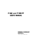
If you are new to postfix, you may want to follow this example by using stack
diagrams, as shown in Figure 4-2. This illustration shows the successive states
of the stack after each number or operation has been processed. Each column
shows the stack at one time. The number on top is the most accessible number on
the stack, ready to be used first by any operation which takes a number from the
stack. We say that this number is at the TOP of the stack.
In the execution of the postfix formula shown above, 42 is placed on the stack
(first column of Figure 4-2) — then 50 is entered. The subtraction destroys
those arguments and leaves the difference, -8. You can follow the rest of the
process similarly.
Each column in Figure 4-2 shows the stack at the time after each successive
number or operation of the formula has been processed. Note that any numbers
which may have been below these numbers on the stack will be undisturbed. Repeat
the above example but insert .S after each number and operator to examine the
stack contents after each operation.
Only numbers go on the stack. Strings or other data structures do not reside
there directly — although some data such as pointers (addresses), length and
offset information, ASCII values, are frequently on the stack.
How many
depth to
maximize
very few
numbers can reside on the stack at one time? RSC-FORTH limits the stack
50 16-bit values in order to keep the parameter stack in zero page to
the R65F11 CPU execution speed. Except for certain recursion problems,
programs ever need a stack depth of more than about 20.
4-8
Figure 4-2. Stack Diagram of Postfix Example
4.1.7 Decimal and Hexadecimal Number Base
Up to now we have been working in DECIMAL . FORTH allows input and output data
to be represented in different number bases. We will consider only two predefined bases now — DECIMAL and HEX . FORTH is initialized to DECIMAL (base 10)
during initial entry or upon commanding COLD . DECIMAL is best used when working
with numeric calculations. HEX operates in hexadecimal (base 16) and is most
useful when working with addresses or logical operations on individual bits.
Type DECIMAL or HEX to change FORTH to the desired base before entering or
displaying data in that base. FORTH will stay in the selected base until the
base is changed or until FORTH is reinitialized (to DECIMAL ). Note that DECIMAL
and HEX affect the input and output data representation and not internal data
handling.
Reinitialize FORTH and put the following numbers on the stack and print them
using different combinations of DECIMAL and HEX .
COLD <RETURN> ( Initializes DECIMAL )
RSC-FORTH VI.5
Press <RETURN> after the word . in each of the following examples:
16 . 16 OK
16 HEX . 10 OK
10 DECIMAL . 16 OK
255 . 255 OK
255 HEX . FF OK
DECIMAL 32767 . 32767 OK
32767 HEX . 7FFF OK
DECIMAL -32768 . -32768 OK
-32768 HEX . -8000 OK
4-9
Note that DECIMAL numbers -1 to -32768 entered on the stack will be displayed in
HEX in 2's complement form with a leading minus sign.
We will examine other number bases later (see Section 4.11.3).
4.2 STACK MANIPULATION
Since most FORTH words use the stack to hold input or output numbers, let's
explore some FORTH words that are used to rearrange or copy numbers near the top
of the stack. While these functions are sometimes necessary, you should avoid
using them where possible. FORTH code is more readable when less stack
manipulation is used. Common stack manipulation words are discussed here,
however, to give you additional experience in working with the stack before
proceeding into other FORTH word descriptions.
4.2.1 DUP ,
DROP ,
SWAP and
OVER
The most common stack manipulation words are DUP , DROP , SWAP and OVER .
Let's explore these, but first place some markers on the stack for reference
DECIMAL 333 222 111 <RETURN>
If we accidentally pull too many numbers from the stack we. will know where we
are. Type .S to check
.S <RETURN>
111
222
333 OK
DUP pushes a copy of the top number onto the stack to create a new top number.
In sequence
123 DUP . . <RETURN>
duplicates 123 on the stack then displays both numbers
123 DUP . . 123 123 OK
DROP deletes the top number from the stack. Try this with
456 789 DROP . <RETURN>
which deletes 789 and displays
456 789 DROP . 456 OK
SWAP exchanges the top two numbers on the stack. Put two numbers on the stack
456 789 <RETURN>
4-10
Use .S to look at the stack
.S <RETURN>
789
456
111
222
333 OK
Now swap the numbers on top the stack and examine the stack with
SWAP .S <RETURN>
which displays
456
789
111
222
333 OK
Notice that the top two numbers are reversed.
second item to be the new top
Now try OVER which copies the
OVER .S <RETURN>
789
456
789
111
222
333 OK
4.2.2 Test and Duplicate with -DUP
A related word -DUP duplicates the top number on the stack only if it is nonzero; otherwise -DUP does nothing. Continuing from the prior example, type
-DUP .S <RETURN>
to show that the top number was duplicated.
789
789
456
789
111
222
333 OK
Let's remove and display the top four numbers from the stack before continuing
CR . . . . <RETURN>
4-11
which displays
789 789 456 789 OK
Now, enter
0 -DUP CR .S <RETURN>
which displays
0
111
222
333 OK
Notice that the top number was not duplicated. -DUP is usually used before an
IF (see Section 4.8.1). In the non-zero case, some action is usually performed
using the value; the extra copy made by -DUP is therefore removed by the IF
processing. In the zero case, no additional action is performed, thus, the extra
copy of the top number is not needed.
4.2.3 Delete the Top Stack Item with
DROP
The word DROP deletes the top item on the stack. Drop the zero now and check
the stack contents
DROP .S <RETURN>
111
222
333 OK
4.2.4 Rotate Stack Items with
ROT
ROT rotates the top three items, moving the third item to the top, the previous
top item to the second, and the previous second item to the third.
For example,
800 700 600 .S <RETURN>
600
700
800
111
222
333 OK
Now rotate and display with
ROT .S <RETURN>
4-12
which outputs
800
600
700
111
222
333 OK
Now remove and display the top three numbers
CR . . . <RETURN>
800 600 700 OK
4.2.5 Copy a Stack Item with PICK
PICK looks down any depth into the stack and copies the nth number from the top
(not counting the n itself) and places it on top.
1 PICK
is the same as
DUP , and
2 PICK
is the same as
OVER . Put several numbers on the stack and check them
40 50 60 70 80 .S <RETURN>
80
70
60
50
40
111
222
333 OK
Now pick the 4th item (i.e., 50), and look at the results
4 PICK .S <RETURN>
50
80
70
60
50
40
111
222
333 OK
4-13
4.3 MEMORY OPERATIONS
Several FORTH words move data between the stack and memory, or from memory to
memory.
4.3.1 16-Bit Store
!
and Fetch
@
The FORTH word
!
(pronounced "store") takes an address from the top of the stack and the 16-bit
value beneath it and stores the value into the address (and address +1).
A corresponding word
@
(pronounced "fetch") takes an address from the top of the stack, fetches the 16bit data from that address (and address +1) and replaces the address on top of
the stack with the data from memory. Both the address and the data are specified
in the current number base. Initialize FORTH and try
COLD
RSC-FORTH V1.6
HEX OK
30FF 200 ! OK
200 @ CR .
30FF OK
which stores 30FF into addresses $200 and $201 with ! , fetches the contents of
addresses $200 and $201 with @ and displays it with . . Try
DECIMAL
16000 HEX 200 ! OK
to store a decimal number in an address entered in hexadecimal. Now display the
data in decimal by
200 @ DECIMAL CR .
16000 OK
which fetches the contents of addresses $200 and $201 and stores it on the
stack, switches to the decimal mode, and outputs the data in decimal when is
commanded.
Now fetch and display the value in hexadecimal by
HEX 200 @ CR .
3E80 OK
4-14
4.3.2 8-Bit Store
C!
and Byte Fetch
C@
Similar words allow byte length data to be stored and fetched. The word
C!
("c-store") stores the least significant 8-bits of the second item on the stack
into the address determined by the number on top of the stack. The word
C@
("c-fetch") accesses the 8-bits stored at the address on top of the stack and
stores it on top of the stack (replacing the address). Try
HEX OK
41 200 C! OK
F4 201 C! OK
which stores 41 and F4 into addresses $200 and $201, respectively. Display the
contents of those address with
200 C@ 201 C@ CR . .
F4 41 OK
4.3.3 Initializing Memory with
ERASE
,
BLANKS
and
FILL
Three words allow a block of memory to be initialized to various values.
ERASE fills memory with zeros ($00) starting at a specified address (second on
the stack) and continuing through the number of bytes specified (top number on
stack)
HEX 200 100 ERASE OK
Spot check with
200 @ 2FE @ CR . .
0 0 OK
Note that if the contents of $2FF were fetched, a non-zero number may be
displayed since '@' fetches two bytes ($2FF and $300) and address $300 was not
erased. The last byte could have been checked with
2FF C@ CR .
0 OK
BLANKS works like ERASE except that memory is initialized to ASCII blank
($20) instead of zeros. Try
HEX 200 100 BLANKS OK
200 C@ 2FF C@ CR . .
20 20 OK
4-15
FILL allows memory to be initialized to a desired value. In addition to the
starting address (third on the stack) and the number of bytes to fill (second on
the stack), the fill bit pattern (top of the stack) is specified). Try
HEX 200 100 FF FILL OK
200 C@ 2FF C@ CR . .
FF FF OK
Try
200 @ 2FE @ CR . .
-1 -1 OK
Notice that the 2's complement value (-1) was displayed when 16-bit numbers were
accessed.
Note also that HEX is not required if FORTH is already in the HEX mode.
4.3.4 Dumping Memory with
DUMP
A block of memory can be displayed using DUMP . A starting address (second on
the stack) and the number of bytes to be dumped (top of the stack) are
specified. Try
HEX
200 14 F8 FILL OK ( Fill 14 hex locations with $F8 )
Enter
200 14 DUMP <RETURN> ( Starting at $200)
to display
200 F8 F9 F8 F8 F8 F8 F8 F8 F8 F8 F8 F8 F8 F8 F8 F8
210 F8 F8 F8 F8 FF FF FF FF FF FF FF FF FF FF FF FF
OK
4.3.5 Moving a Block of Memory with CMOVE
It is often useful to move a block of data from one area of memory to another.
This can be done with the word CMOVE which takes three arguments on the stack:
a from-address, a to-address, and a byte count. It moves the given number of
bytes starting with the first address to the area of memory starting at the
second address.
Try
200 40 80 FILL OK
240 40 FF FILL OK
200 280 8 CMOVE OK
240 288 8 CMOVE OK
280 10 DUMP
280 80 80 80 80 80 80 80 80 FF FF FF FF FF FF FF FF
OK
4-16
CMOVE works from the left to right, so be careful if the "from" and "to" memory
areas overlap.
4.4 DEFINING YOUR OWN OPERATIONS
FORTH allows you to create your own operations. These new FORTH words become an
integral part of the language, just like those which are pre-defined in RSCFORTH. Your new words can take any number of arguments from the stack, and
return any number of results.
The names of your operations can have up to 31 characters. They can use any
ASCII characters except blank, delete, null and carriage return. For instance,
an operation name could be a number, or even be non-displaying or non-printing
control characters, although such names are discouraged. Even names already used
by the system may be redefined as something else; therefore there is no reserved
word list in FORTH. When a name is redefined, the old definition becomes
inaccessible for later use in the program (although all earlier references to
that name will remain as before). So, do not redefine a name if you want to use
the old definition later.
Names which are descriptive of the function they perform make the code easier to
read. Good choice of names is important for later use of the code, especially
by other programmers.
As new words are defined, they are added to the FORTH vocabulary (described in
more detail in Section 5.6). These definitions are normally stored in RAM
starting at address $0404 and build upward in memory. (They can also be stored
in PROM/ROM in normal or headerless target compiled format as described in
Section 11.) The FORTH word VLIST allows you to check what words have been added
to the FORTH vocabulary.
4.4.1 Colon-Definition
Suppose we want an operation to take the number on top of the stack, multiply it
by 5, and print the result. Let's pick the name TEST-OP . We could define it
simply as
: TEST-OP 5 * . ; <RETURN> OK
(Later we will rewrite this definition, using indentation and commenting
conventions for more readable code). Enter the colon-definition as follows
a. Start the definition with a colon which tells FORTH to look ahead in
the input stream for the word name. Follow the colon with a space.
b. Enter the word name (up to 31 characters). The FORTH word here is
TEST-OP .
c. Enter the definition of the word.
TEST-OP does
the following:
1. Puts 5 on the stack
2. Multiplies the top two numbers, i.e., the number on top of the
stack when TEST-OP is executed by the 5 put on the stack by
TEST-OP .
4-17
3. Prints the result, i.e., the top number on the stack.
d. End the definition with a semi-colon (be sure to insert a space
first). A FORTH definition may be continued on as many lines as
needed.
This TEST-OP operation takes one number from the stack, as we have seen. It
does not return any result (but if the . were omitted, the product would stay
on the top of the stack). Note that no formal parameters are used to show the
inputs and outputs of an operation. These are implicit — TEST-OP takes one
argument because it puts one number (5) on the stack then performs a multiply
which uses two numbers (the 5 and one other). Check the operation of TEST-OP
by placing a value on the stack and executing TEST-OP , e.g.
6 TEST-OP <RETURN> 30 OK
8 TEST-OP <RETURN> 40 OK
If the word being defined is already in the vocabulary dictionary, the message
<name> NOT UNIQUE will be displayed. The NOT UNIQUE message is displayed only as
a reminder that you have redefined a word which was previously defined and has
no effect on the compilation process, e.g.
: TEST-OP 10 * . ;
TEST-OP NOT UNIQUE OK
Now test it with
6 TEST-OP <RETURN> 60
8 TEST-OP <RETURN> 80
Note that only the new definition of TEST-OP is found and executed.
4.4.2 Find a Word in the Dictionary with
'
Use the word ' (pronounced "tick") to find if a word is already contained in
the dictionary and to return its parameter field pointer address (PFAPTR).
(Note: This varies from most FORTH systems which return the parameter field
pointer (PFA). This additional level of indirection is necessary to run
separated heads and codes).
Type the word <name> after the word ' , i.e. ' <name>
FORTH will respond with OK for a found word and put the word's parameter field
pointer address on the stack (See Section 5.5 for description of the parameter
field pointer address). If not found, the name is echoed with a "?" and the
stack is cleared.
4-18
Check
TEST-OP
now (and print the address in the dictionary)
HEX OK
' TEST-OP <RETURN> OK
.S
432 OK
We can also run a VLIST to determine if TEST-OP is in the dictionary and to
verify the address returned by ' . This is easy in this case since only two
colon-definitions have been added to the dictionary and these two entries are
printed immediately. Press any key to terminate VLIST.
VLIST
432 TEST-OP 41B TEST-OP 4DB TASK 3844 ADMP
3805 ;DUMP
37CF FORMAT 367E FMTRK 3674 BANKEXECUTE
( A key was pressed here)
OK
While both versions of TEST-OP are listed, only the version at address 432 is
valid since it was defined last.
4.4.3 Print a Message with
."
You can print a message of up to 127 characters with the word ." (dot-quote).
Start the message one or more spaces after the ." word. Terminate the message
with " (a double quote). Be sure to leave a space after the ."
Now define a new word to use
."
: MULTIPLY
CR ." ANSWER=" 5 * . ; <RETURN> OK
and test it
DECIMAL
108 MULTIPLY
ANSWER=540 OK
1345 MULTIPLY
ANSWER=6725 OK
4.4.4 Commenting
Because the inputs and outputs are not explicit in FORTH code, it is very
important to show them in the documentation. It is recommended that they be
included as comments in the code and also in a separate glossary of operations.
Each glossary entry should include the inputs, outputs and a short description
of what the operation does — usually two or three sentences are enough.
Comments in FORTH are enclosed in parentheses. A space must follow the left
parenthesis because the left parenthesis is itself a FORTH word, which causes
FORTH to look for a closing delimiter. The closing right parenthesis need not be
preceded by a space however, since it is a delimiter and not an operation.
4-19
A <RETURN> also acts like a right parenthesis, to terminate a comment. FORTH
comments can be included on as many lines as needed; however, the comment must
start with a left parenthesis followed by a space on each new line.
A conventional form of comment first lists the inputs, then three dashes, then
the outputs. A period may be used to separate the last output word from the
words of any description of the function of the operation. Therefore the TESTOP definition could look like
: TEST-OP ( N --- . MULT BY 5 AND PRINT)
5 * . ;
A common style is to have only the colon, the word being defined, and the
comment on the first line, then indent subsequent lines three columns. If the
comment is too long, put it on the second line. There is no compiled code
penalty for including comments and spaces so they can be used freely to improve
readability when preparing object code for mass storage; or if a listing is
being made of the source. When interactively entering commands from the keyboard
comments are not very useful.
When there is more than one input or output in a command, the right-most numbers
are toward the top of the stack. A comment for a definition of a multiply
operation might therefore be
: MPY ( N1 N2 --- . MULTIPLY & PRINT )
* CR . ;
Note that an empty comment must consist of at least a left parenthesis, two
spaces, and a right parenthesis. The reason is that the parsing word ( WORD in
FORTH) skips over leading occurrences of the delimiter. So if you leave only one
space, as in
( )
the first character encountered by WORD is the right parenthesis, therefore the
system skips it and continues looking for another right parenthesis.
4.5 EXECUTING AND COMPILING USING SOURCE
Up to now you have been operating in a manner where FORTH operations are
compiled or executed immediately upon entry in an interpretive mode. If a new
FORTH word is formed using a colon-definition (see Section 4.4) the word is
immediately compiled and entered into the FORTH vocabulary upon completion of
entry. Upon commanding the new FORTH word, the defined function is executed.
FORTH words can also be compiled and executed in a batch mode. In this mode,
the FORTH words are compiled or executed upon entry from mass storage. The
source program for colon-definitions is not lost upon compilation with this
technique, therefore, changes can easily be made without requiring re-entry of
the whole program.
4-20
There are two methods of batch compiling in RSC-FORTH. The first method uses the
standard FORTH technique of multiple RAM buffers and 1024 byte screens. This
technique is commonly used for manipulating, saving, and retrieving data files
on mass storage. This method is discussed in Section 12.
The second method of batch compiling accepts an input from an intelligent
terminal, or download from another computer. Entering the word SOURCE causes the
RSC-FORTH system to enter an XON-OFF protocol. It begins by transmitting an XON
character when SOURCE is first executed and accepts inputs until a null or
carriage return is received, or until the number of characters per line limit is
reached. It then transmits an XOFF character and interprets the received line.
When interpretation is finished for that line, an XON is transmitted to
reestablish communications for another line. When the word FINIS is executed, or
an error is detected, the compilation stops and control is returned to FORTH.
Characters sent to the RSC-FORTH system are not echoed to the sending unit. Most
terminals and computer systems that have the XON-XOFF protocol can be used with
SOURCE.
4.6 DO LOOPS
4.6.1 DO ... LOOP
The DO and LOOP statements allow repeated execution of a block of code.
For example, the following definition creates a word SERIES , which prints a
series of 25 numbers, zero through 24:
: SERIES ( --- . PRINT A SERIES )
CR 25 0 DO I . LOOP ;
Now execute
SERIES
0 1 2 3 4 5 6 7 8 9 10 11 12 13 14 15 16
17 18 19 20 21 22 23 24 OK
DO must always be paired with either LOOP or +LOOP (described in Section
4.6.2). The code section which they enclose can be of any length. This code is
executed repeatedly, and an index value, I, is available.
When DO sets up the loop (at run-time), it always takes two arguments from the
stack. The top stack number (0) is the initial index value of the loop, and the
second argument (25) is the final value plus one. If the initial value is zero,
as is often the case, the second argument is the number of times around the
loop. Also, ordering the loop limits this way makes the loop upper limit more
accessible from outside a definition. We can see how this is done in the
definition of NSERIES, below.
The loop index value is kept by the system and incremented automatically. The
FORTH word I retrieves this index and copies it onto the stack. In the example
above, the index value is zero the first time through the loop, then it is 1, 2,
etc. through 24. In this example, the index is printed each time. SERIES takes
no arguments from the stack and returns no results.
4-21
The recommended code-writing style for using DO and LOOP is to have the
entire loop in a single line if possible; if not, LOOP should be indented to
the same column as its corresponding DO . This style makes the program's
structure easier to see.
The definition
: NSERIES ( N --- . VARIABLE SERIES)
CR 0 DO I . LOOP ;
creates NSERIES , which is almost like SERIES , except that it takes one
argument from the stack, the number of times around the loop.
Now execute
NSERIES
10 NSERIES
0 1 2 3 4 5 6 7 8 9 OK
Redefine
SERIES
now in terms of
NSERIES , as
: SERIES ( --- . PRINT A SERIES)
20 NSERIES ;
This redefinition will cause a "NOT UNIQUE" warning message to be printed. The
warning can be ignored in this case; remember, its purpose is to let you know
that the word has also been defined previously. As mentioned before, FORTH
allows any word to be redefined — even the system words such as DO itself. Any
further use of the word will refer to the latest definition, but all earlier
uses still refer to the definition which was in effect when the earlier
references were compiled.
Execute
SERIES
now.
SERIES
0 1 2 3 4 5 6 7 8 9 10 11 12 13 14 15 16
17 18 19 OK
In the examples above, notice that the only difference between SERIES and
NSERIES is that the latter does not place a loop terminating value on the
stack. Instead, it uses whatever was on the stack when NSERIES was executed.
The NSERIES example also shows that the arguments to DO , the loop initial
and terminating values, need not be literal numbers; instead they can be
computed or obtained in any way. DO doesn't care how its arguments got onto the
stack. This feature helps keep FORTH code modular and reduces side effects when
changes are made.
DO ... LOOP , and the other control structures which will be introduced later,
can only be used inside colon-definitions, i.e., they cannot be executed
directly as commands at the terminal. DO and LOOP are in a special class of
words called immediate words. These are not compiled like other words used in
colon-definitions, but instead they execute at compile time to handle special
compilation functions, e.g., to compile an internal branch back from the LOOP
to its corresponding DO. Immediate words are discussed in Section 5.
4-22
An example of DO ... LOOP is a one millisecond time delay word (this example
assumes a 1 MHz internal clock rate):
: MS ( N --- . MILLISECOND DELAY)
0 DO 5 0 DO LOOP LOOP
CR ." TIME-UP" CR ;
This word will cause delays of n milliseconds when used by putting n on the
stack and then typing the word. To execute a 9 millisecond delay, simply enter
9 MS
At the end of the delay, the message
TIME-UP
is displayed. Try it with larger delays, e.g., 1000, to visually notice the
delay time.
4.6.2 +LOOP
The DO ... LOOP index always increments by 1. Another word, +LOOP , allows
other increments. Each time around the loop, it takes a number off the stack for
the increment, DO ... 2 +LOOP would increment by 2. The increment can be
computed and it can change during loop execution. It can also be negative. The
following word causes an odd number in the range 1 to N to be printed.
: ODD-SERIES ( N --- . PRINT ODD SERIES)
1 CR DO I . 2 +LOOP ;
Execute ODD-SERIES with 25 as the input number (don't forget to put the input
number on the stack or a STACK EMPTY error may occur).
25 ODD-SERIES
1 3 5 7 9 11 13 15 17 19 21 23 OK
4.6.3 LEAVE
LEAVE is another word used with DO loops. If LEAVE is executed within a
loop, it will set the limit to the index value, causing the loop to exit when
LOOP or +LOOP is next executed. LEAVE (and also the index I ) can only be
used inside a DO loop.
4.7 COMPARISON AND LOGIC OPERATIONS
The DO loop is one form
described later (IF ...
... WHILE ... REPEAT ,
(truth values) to control
Booleans on the stack and
of structured control in FORTH. Other structures
THEN , ELSE ... THEN , BEGIN ... UNTIL , BEGIN
and BEGIN ... AGAIN ) may test Boolean values
program execution. Comparison and logic words place
then the control words use these values.
4-23
4.7.1 < ,
>
and
=
Simple FORTH comparison words are < (less than), > (greater than) and =
(equal). Each of these operations takes two arguments from the stack (destroying
those arguments) and returns one result (a Boolean) to the stack. The second
item on the stack is compared to the top item in accordance with the FORTH word.
If the comparison is true, a true ("1") is returned; if false, a false ("0")
value.
4.7.2
U< , 0<
and
0=
Other comparison operations are U< , 0< and 0= . U< (unsigned less than)
compares the top two stack numbers as unsigned 16-bit integers (see Section
5.1). 0< (zero less than) and 0= (zero equals) differ from the others in
taking only one argument from the stack; it is tested for being less than zero,
or equal to zero, respectively. 0< leaves a true on the stack if the number is
less than zero, otherwise a false is left. 0= returns a true if the number
equals zero, otherwise a false is returned. 0= works the same as
0 =
written as two words; similarly for 0< . The one-word forms are more efficient,
however (faster execution).
0= is equivalent to a logical "not", because it reverses the truth value of the
top stack item (it changes 0 to 1, and 1 or any other non-zero value to 0).
Experiment with the comparison operations
HEX
10 20 < . <RETURN> 1 OK
20 10 = . <RETURN> 0 OK
5 0= . <RETURN> 0 OK
5 5 - 0=. <RETURN> 1 OK
10 -10 < . <RETURN> 0 OK
10 -10 U< . <RETURN> 1 OK
1 0= 0= . <RETURN> 1 OK
8 0= 0= . <RETURN> 1 OK
Note that the Boolean false value is always zero and any non-zero value (not
only '1') is taken as a Boolean true. However, the value returned by these
comparisons is always 0 or 1.
4.7.3 Logical Operations
Logical operations AND , OR , and XOR (exclusive OR ) are provided. These
are bit-wise operations. Each takes two arguments from the stack and returns one
result. Each of the 16 bits of the result is obtained by applying the logical
operation to the corresponding bits of the arguments. All bit positions are
treated independently.
4-24
HEX
F7 01 AND . <RETURN> 1
08 01 OR . <RETURN> 9
F7 01 XOR . <RETURN> F6
The word NOT is provided as a synonym for 0= (see Section 4.7.2) to improve
readability in logic expressions. Note that NOT is not a bit-wise operation;
it is only a Boolean inversion and just returns the right-most bit of the word.
To negate all the bits of a word (i.e., to take its one's complement), use
-1 XOR
For example
HEX
AAAA -1 XOR . <RETURN> 5555
AAAA FFFF XOR . <RETURN> 5555
These logical operations can also be applied to truth values returned by
comparisons; in this case, only the right-most bit of each word is important.
For example, suppose that a word ?HOT has already been defined to return a
value of true if a sensor detects a temperature higher than a pre-set limit,
false otherwise. Also suppose that a voltage value is previously stored on the
stack. The test
8 > ?HOT OR
will return true if the voltage (on the stack) is greater than 8, or the
temperature is high, or both. In this example the voltage value on the stack is
first compared to 8 by use of the relational operator. This results in a Boolean
value left on the stack. Then ?HOT puts another Boolean on the stack and the two
Boolean values are OR'ed together.
Note that
?HOT 8 > OR
would be erroneous in this case, because the Boolean left on the stack by ?HOT
would be compared with the 8 and the result of that comparison (always false)
would be OR'ed with the voltage that was on the stack before this phrase was
extended.
4.8 CONDITIONAL CONTROL STRUCTURES
The following FORTH control structures test a Boolean result generated by the
comparison or logical operations, and direct the flow of program execution
accordingly.
4-25
4.8.1 IF ... ELSE ... THEN
As with other control structures, the IF and THEN must be used as a pair; if
they are not, error message #19 or #20 will be generated (see Appendix E) at
compile-time. Any correct block of FORTH programming may occur between the IF
and the THEN .
The IF takes one argument, a Boolean value, from the stack. If it is true
(non-zero), the code between IF and THEN is executed; if false (zero), that
code is skipped. In either case control resumes with the THEN . For instance,
GET-VOLTAGE 8 > ?HOT OR
IF SHUT-DOWN THEN
will execute the (predefined) operation SHUT-DOWN if the previously defined
word GET-VOLTAGE returns a value greater than 8 or ?HOT returns true (or
both).
An optional ELSE clause allows a block of code to be executed only if a test
is false. For example, the simple control loop
10000 0
( Loop 10000 times)
DO
GET-VOLTAGE 8 > ?HOT OR
( Danger?)
IF GO-SLOWER ELSE GO-FASTER THEN
LOOP
repeatedly tests whether temperature or voltage exceed their limits, and
executes predefined operations GO-SLOWER or GO-FASTER accordingly.
4.8.2 Nesting Control Structures
The previous example shows that control structures can be nested; an IF ...
ELSE ... THEN is inside a DO ... LOOP . Any of FORTH's control structures can
be nested within any other to any practical depth. The recommended coding
technique is to keep each definition short and simple, breaking complex
operations into two or more shorter ones. For this reason, great depth of
nesting is not normally used. For instance, in the examples above, operating
like GO-SLOWER and GO-FASTER may themselves contain complicated control, it
is best to define them as separate words to avoid cluttering a single word with
many levels of nesting. Also, this is an example of top down coding as GETVOLTAGE , GO-SLOWER , GO-FASTER and ?HOT may not exist in final form yet as
the programmer experiments with the overall design of the control loop.
Of course GET-VOLTAGE , GO-FASTER and ?HOT
before the loop would compile in a definition.
name encountered would cause the error message
<name>?
to be output.
4-26
must exist in some form at least
If not, the first unknown word
Another recommended coding style is to indent IF ... THEN or IF ... THEN ...
ELSE like DO ... LOOP . Keep the whole structure on one line if it is short
enough, otherwise, indent the IF , ELSE (if present) and THEN to line up
vertically. Each new level of nesting structure should be indented at least one
space.
4.8.3 Masking and Setting Bits
The operations used for masking — selecting certain bits within a 16-bit word,
and turning them OFF or ON , or complementing or testing them — were largely
covered in Section 4.7.3. This section further explores these operations in many
of the control applications to which the R65F11 and R65F12 microcomputer is well
suited.
Mask values are best presented in hexadecimal. In hexadecimal, the values 0000
through FFFF can be input; a minus sign can also be used to input numbers 8000
to FFFF (-8000 to -1). The dot (period) works for output, but if the first bit
is set, use the phrase
0 D.
(zero, double-precision print) instead, to avoid having the number interpreted
as negative. This makes the top stack item a double integer, whose most
significant 16 bits are zero, and then uses the double integer print word to
output the resulting positive 32-bit integer.
In the following examples we will be changing or testing the last three bits of
a word; i.e., the mask value will be 0007 (last three bits set, all others off).
This value could be written simply as 7, but the leading zeros are
conventionally used on both address and mask values for program clarity. The
mask of course need not be a literal value as shown in these illustrations; it
could be computed, perhaps by previous logical operations, or input from the
terminal, etc.
To turn ON the last three bits of the word on top of the stack (leaving all
other bits unchanged), execute
0007 OR
The OR operation, as described earlier, does a logical OR of each bit
independently. The sign bit is treated like any other. (In these examples, we
will assume that HEX has been executed to set the number base to 16.)
Similarly to turn OFF the last three bits, use
FFF8 AND
To test if any of the last three are ON, use
0007 AND
4-27
The stack top will now be zero if none of the last three bits were ON, and nonzero otherwise. This value can be used as a Boolean by IF , UNTIL , or
WHILE , but be careful if the value is used as input to another AND or OR ;
input to these operations should be a Boolean zero vs. one, not zero vs. nonzero. If such further logic is to be done, use
0= 0=
which leaves the truth-value unchanged but converts the zero/non-zero result
into a more correct zero/one Boolean. Use
0007 AND 0= 0=
or
0007 XOR
to complement (reverse values of) the last three bits of the top stack word.
To complement all bits, use
FFFF XOR
(which could also be written
-1 XOR
because the numeric representations FFFF and -1 are the same in 16-bit 2'scomplement arithmetic.)
With the operations AND , OR , and
two or more arguments can be used.
XOR , any truth-value functions of one,
4.8.4 BEGIN ... Loops
In a BEGIN ... UNTIL loop, the UNTIL takes a Boolean value from the stack.
If false, it loops back to the BEGIN ; if true, it terminates the loop, i.e.,
the loop continues UNTIL a condition is true. The following loop executes
until ?HOT is true (non-zero):
BEGIN
PERFORM-AN-ACTION
?HOT ( STOP IF HOT)
UNTIL
The BEGIN ... WHILE ... REPEAT loop is almost opposite; it will continue to
execute the statement(s) between WHILE and REPEAT while the condition
between BEGIN and WHILE is true. WHILE tests the Boolean; if true, it does
nothing, allowing control to remain in the BEGIN ... REPEAT loop; if false, it
branches out of the loop (to beyond the REPEAT ). The REPEAT always branches
back to the BEGIN . The following loop is almost the same as the UNTIL loop
above
4-28
BEGIN
?HOT 0=
WHILE
PERFORM-AN-ACTION
REPEAT
The difference is that the words contained between WHILE and REPEAT loop can
execute zero times, but the words in the BEGIN ... UNTIL loop will always
execute at least once since the test is made at the end of the loop, not the
beginning. Note the use of 0= (equivalent to a logical NOT ) to reverse the
truth-value returned by ?HOT.
A BEGIN ... AGAIN structure creates an infinite loop. AGAIN takes no
arguments from the stack — it always causes control to return to its
corresponding BEGIN . This structure could be used in a real-time control
program to execute a final procedure until interrupted. It is also possible to
exit this loop with a ;S word.
All of these structures can be nested within any others. Again, avoid long or
complicated definitions. Short definitions make programs easier to read, debug,
and modify.
4.9 DATA STORAGE
How can you get an address of available memory to use for data storage?
One way to find available memory for data structures is to use the top of your
RAM memory and work down, since your word definitions start at $411 and work up.
For instance, if you have 8K of RAM, addresses such as $1FOO-$1FFF might be used
for data, depending on the size of your program (i.e., the number and size of
your word definitions).
Another approach is to allocate memory for data within the dictionary — the
words
CONSTANT , VARIABLE and ALLOT , described in the next chapter, do this.
4.9.1 Find Next Dictionary Location with HERE
The word HERE returns the address of the next available dictionary location.
HERE can be used to determine the size, i.e., the memory required of a colondefinition.
The procedure is to type:
HERE ( puts current dictionary address on stack)
Enter the colon-definition
: <name> --- :
4-29
Enter the current dictionary address on stack, swap to subtract the smaller
address from the larger, and then print the size of the defined word.
HERE SWAP - .
Enter the following example of a square function. Note the first available
dictionary location before and after entry of the SQUARE colon-definition. The
length of the colon-definition in the dictionary is $15.
HEX OK
HERE DUP
: SQUARE
HERE DUP
SWAP - .
. <RETURN> 411 OK
DUP * . ; OK
. <RETURN> 426 OK
<RETURN> 15 OK
Check the operation of the SQUARE word.
DECIMAL
4 SQUARE <RETURN> 16
4.9.2 Use PAD for Temporary Storage
A common location for temporary storage in most FORTH systems is the address
returned by the word PAD , and the memory above. In RSC-FORTH, PAD returns a
starting address two bytes below the Terminal Input Buffer (TIB) in the USER
area of RAM. PAD must be used with caution therefore in RSC-FORTH: the space
below PAD is used by RSC-FORTH itself for temporary storage. Let's restart and
check the starting address of the FORTH dictionary using HERE and the starting
address of the temporary storage area using PAD .
COLD
RSC-FORTH V1.6
PAD HERE HEX .S
411
37E OK
In most FORTH systems
PAD
starts 68 bytes above the start of the FORTH
dictionary. To make RSC-FORTH compatible with other FORTH systems, define PAD
as follows:
DECIMAL
: PAD HERE 68 + ;
Since PAD is located relative to the current top of the RAM dictionary it will
change when any new words are defined, or when words already in the dictionary
are forgotten. Usually this is not a problem because any particular test or run
would move data into its temporary storage at PAD , and not rely on data stored
there previously.
As an example, add a word to the FORTH dictionary that can be used to check
where HERE and PAD are located, as other words are either added or deleted
from the dictionary. Then use it first to check itself.
4-30
: CK-PAD ( --- . CHECK PAD & HERE)
PAD HERE HEX
CR ." HERE=" .
CR ." PAD=" . ;
Enter
CK-PAD
and compare the results
CK-PAD
HERE=43D
PAD=481 OK
Now the memory fetch and store words can be tested, using
memory. Try the sequence
PAD
as available
DECIMAL OK
PAD 20 BLANKS OK
15 PAD ! OK
15 PAD 10 + C! OK
PAD 10 HEX DUMP
XXX F 0 20 20 20 20 20 20 20 20 F 20 20 20 20 20
OK
The output shows the blanks (ASCII $20), the 15 ($OOOF) stored as a word (with
the bytes reversed by the 6502 CPU so it looks like OFOO),and the 15 ($F) stored
as a byte 10 bytes later. The
10 +
shows use of an offset to an address; this technique can be used to create data
structures such as arrays, records and fields, etc.
4.9.3 Increment Memory with +!
A very useful memory modification word is +!
(pronounced "plus store"). +!
takes a stack value and a memory address and adds the value to the contents of
the address; for example, it is used for incrementing counters in memory.
Define the word BUMP to increment the contents of address $600 by one, eight
times, and prints the contents of $600 after each increment.
HEX
: BUMP
CR 8 0 DO 1 600
+! 600 C@ . LOOP ;
Initialize $600 to zero and execute
BUMP
0 600 C!
BUMP
1 2 3 4 5 6 7 8 OK
4-31
Try it again but first initialize $600 to $10
10 600 C!
BUMP
11 12 13 14 15 16 17 18 OK
Define another function UPBY6 to increment the memory contents by six and
display the results
: UPBY6
CR 8 0 DO 6 600
+! 600 C@ . LOOP ;
Clear $600 contents and try it.
0 600 C! OK
UPBY6
6 C 12 18 1E 24 28 30 OK
4.9.4 Exclusive-OR Memory Using
TOGGLE
TOGGLE takes an address and a one-byte mask as arguments; it does an exclusiveOR between the byte and the address contents, updating the latter.
Experiment with TOGGLE by first initializing $600 to $FO
HEX OK
FO 600 C! OK
TOGGLE the value
600 55 TOGGLE OK
Print the result
600 C@ . <RETURN> A5 OK
Note that both +! and TOGGLE could be performed otherwise using multiple
FORTH words, however, these words are convenient, and use less memory than
multiple definitions.
4-32
4.10 CONSTANTS AND VARIABLES
4.10.1 CONSTANT
The word CONSTANT creates a new FORTH word which returns a value to the stack
whenever it is executed. For example,
50 CONSTANT X
creates a constant named X . When this new word is executed, it will return 50
to the stack. Print the value of X with
X . <RETURN> 50
Constants are commonly used to give names to values which are fixed parameters
in programs.
The same result could also have been accomplished by using a colon-definition,
: X 50 ;
But the former is more efficient in both memory use and run-time speed.
If it is necessary to change the value of a CONSTANT in RAM before storage of
the program in ROM it can be done using the following technique
<new value> ' <name> @ !
For example, to change the 50 in the prior example to 78, use
78 ' X @ !
check it now with
X . <RETURN> 78
Note that trying to change the value of a constant, by putting a new definition
of the constant in the dictionary after compiling a word using it, will not work
since existing linkage to the prior value will not change.
4.10.2 VARIABLE
VARIABLE is like CONSTANT , but the word it creates returns the address of a
value instead of the value itself. Therefore new values can be stored into the
variable. Try
50 VARIABLE Y
Y @ . <RETURN> 50
60 Y !
Y @ . <RETURN> 60
( Define variable Y, initialize
to 50 )
( Fetch and print Y )
( Store 60 into Y )
( Fetch and print Y )
4-33
Although this example illustrates the use of the word VARIABLE to initialize
the value (to 50), the better practice is to always create the variable as zero
or some dummy value, and initialize if necessary in an initialization section of
the code. If the program is later moved to ROM, the variable location will have
to be in RAM, where it cannot be initialized at compile time (see Section
4.10.4).
4.10.3 Defining Words
CONSTANT and VARIABLE are both in a special class of words called "defining
words". Defining words add new words to the dictionary. The only other defining
word we have seen so far is the colon used to begin colon definitions. As with
the colon, the names created by CONSTANT and VARIABLE can be up to 31
characters long and can redefine other names.
The RSC-FORTH system includes eight defining words which are commonly used: the
colon, CONSTANT , VARIABLE , USER , VOCABULARY , CODE , <BUILDS ... DOES>
, and ;CODE . Each defining word is equivalent to a data type or class of
operations. Later we will learn how the user can create entirely new data types
(new defining words) by using the special operations <BUILDS ... DOES> or
;CODE .
4.10.4 USER
USER is a defining word which creates a different kind of variable. A user
variable, like an ordinary variable, returns an address of where a value is
stored. But user variables store their values in a special "user area" which is
normally in RAM from address $300 through $37F; not in the dictionary (which may
be in ROM). (The name "user area" originated on large, multi-user FORTH
systems. Each user has a unique memory area for system variables, e.g., the
number base currently in effect for that user, and the programmer's own
variables.) The user variables are defined in Appendix G.
USER , like CONSTANT and VARIABLE , takes one argument from the stack, but
the argument is not an initial value; instead it is an offset from $300 into the
user area. For example,
60 HEX USER A
62 HEX USER B
creates two variables, A and B, with offsets of $60 and $62 bytes, respectively,
from the user variables base address at ($300). USER is configured to allow
offsets of 0-255 ($FF).
Offsets between $54 and $60 should be used however, to place the USER variables
at $354 through $360. Note that offset values below 84 ($54) and particularly
above 96 ($60) may cause conflict with other system user variables, PAD , or the
Terminal Input Buffer (see Appendix G). Be sure that your assignment allows one
word (two bytes) for each user variable.
4-34
4.10.5 ALLOT
FORTH programs can use arrays, records, virtual arrays (if mass storage is
available), and other data structures. The most elegant way to create such
structures is described in the chapter on user-defined data types. But a simple
method which is sometimes good enough uses VARIABLE and another word, ALLOT .
ALLOT takes one argument from the stack and leaves space for that many bytes in
the dictionary. For example,
0 VARIABLE RECORD
creates a variable called RECORD ; two bytes are available for the value.
Suppose 100 bytes are needed. Then
0 VARIABLE RECORD 98 ALLOT
would create the variable
RECORD
and leave the 98 extra bytes for it.
Suppose RECORD were to be used for a customer name and address; the programmer
could create such operations as
:
:
:
:
:
LAST-NAME 0 + ;
FIRST-NAME 20 + ;
MIDDLE-INITIAL 30 + ;
ADDRESS1 31 + ;
ADDRESS2 51 + ;
Then
RECORD FIRST-NAME
would return the address of the start of the FIRST-NAME field.
In a similar manner, arrays can be generated and manipulated. To define an array
of 300 bytes, use
0 VARIABLE ARRAY 298 ALLOT
To fetch the nth value of this array, one can use
: GETN ARRAY SWAP 2 * + @ ;
Type
41 GETN
to place the value of the 41st element onto the stack.
4-35
4.11 CHANGING THE NUMBER BASE
We have already seen the words DECIMAL and HEX , which set the number base to
10 and 16, respectively. FORTH can work in any number base (even above 16) but
in practice only 10, 16, 2, and perhaps 8 are commonly used.
The number base can be changed by storing the desired base value into the user
variable BASE , which is available as part of the system. For example,
2 BASE !
sets FORTH terminal input and output to binary. The user could define a word to
do this,
: BINARY 2 BASE ! ;
and then later just execute
BINARY
The words DECIMAL and HEX similarly change BASE ; for convenience, these
words are already defined in the system as supplied.
Note that BASE only affects input and output. Internal computation is always
in binary so there is no computation-speed penalty for using different bases.
Also note that the base will remain as set until changed again.
You can easily determine the current I/O number base with BASE @ DUP DECIMAL .
The word @ puts the value of BASE on the stack. DUP duplicates the base
value for the later restore. DECIMAL converts the I/O number conversion base
to decimal and . prints the base and removes it from the stack.
If you need to check the base often, you can define a colon-definition word to
do it, such as
: BASE? BASE @ DUP DECIMAL . BASE ! ;
When a colon-definition is compiled, the base in effect at compile time is the
one that counts. Notice that the following code is erroneous and fails to
compile:
DECIMAL
: MASK HEX 00FF OR ;
00FF?
The 00FF is unrecognized because the base is decimal at compile time; the word
HEX does not change the base immediately (as was intended), but compiles as
part of the definition of MASK. It will change the base when MASK was
executed. The correct code is
4-36
HEX
: MASK 00FF OR ;
DECIMAL
A possible source of confusion is the fact that in binary, the numbers 2, 3 and
4 (as well as 0 and 1) are correctly recognized on input. This happens because
the numbers 0-4 are so commonly used that they were made into constants to save
memory space. Since these common numbers are FORTH words in the dictionary, they
are recognized regardless of the number base in effect.
4.12 OUTPUT WORDS
4.12.1 Print Right-Justified with
.R
We have already seen the word . (dot) used for printing numbers. Other
operators are available to output single-precision and double-precision numbers
left-justified and right-justified.
The word .R prints a 16-bit number right-justified in a field of a given
width. It takes two arguments, the number and the desired field width; the
latter is on top of the stack. For example,
4734 CR 26 .R CR
4734
OK
prints 4734 right-justified 26 columns. Note the use of
print on the following line.
CR
to cause OK to
Later (in Section 5.2.2) you will see that the corresponding double-precision
(32-bit) output word D. prints a double-precision signed number left-justified,
while D.R prints a double-precision signed number right-justified.
4.12.2 Output Spaces with
SPACE
and
SPACES
The word SPACE outputs one space, and SPACES takes one argument from the
stack and outputs that number of spaces; such as
CR ." TEXT1" 4 SPACES ." TEXT2" CR
TEXT1
TEXT2
OK
4.12.3 Output a Character with
Use the word EMIT
it. For example
EMIT
to take the top stack number as an ASCII value and output
DECIMAL 65 EMIT
outputs A to the terminal.
4-37
Use EMIT in conjunction with the input word
display an entered character. Try it with
KEY
(see Section 4.13.1) to
KEY <RETURN> <input character> OK
EMIT "Entered character" OK
Note that the input character (from the keyboard) is not output by the word KEY
— only by EMIT. Now, define one word to do both
: ?KEY KEY CR EMIT CR ;
Check it with
?KEY <RETURN> A
A
OK
?KEY <RETURN> #
#
OK
Now try a few other characters of your own choice — try lower case letters also.
4.12.4 Output a String with TYPE
To display an ASCII string given its address and length (length on top of the
stack), use TYPE . Try
HEX 600 10 TYPE
which displays 16 bytes starting from
HEX
address 600.
This will convert whatever is in these locations to ASCII and output it — which
will display random characters and spaces until known data is placed in these
locations.
Try it after first entering in string of data from the keyboard in RAM using the
word EXPECT (see Section 4.13.2).
DECIMAL 600 40 CR EXPECT
<character string> <RETURN> ( if less than 40 characters)
600 40 CR TYPE
Try it with a message of up to 40 characters. Note that if the string is less
than 40 characters, whatever is in memory between the last entered character
through the 40th character will be converted and displayed.
4.12.5 Prepare to Output a String with COUNT
Sometimes a string is stored as a length byte followed by the string itself, and
only the address of the string (of the length byte) is on the stack; this is an
alternate form for storing a string.
4-38
To convert from this form, the word COUNT
arguments required by TYPE. Therefore,
takes the address and returns the
COUNT TYPE
displays a string given the address of its length byte. Try the following
HERE COUNT CR TYPE
TYPE
More advanced output operations are discussed in Section 5.3, "Output
Formatting". These allow you to create your own output formats which may include
such characters as decimal points, dollar signs, and commas. More on string
handling is discussed in Section 5.4.
4.13 INPUT WORDS
FORTH handles input by taking all characters (tokens) separated by spaces and
first trying to look them up in the dictionary. If the token is not in the
dictionary, the system tries to make a number of it, using the number base
currently in effect. Then if the token contains a non-digit character, the
system reports an error condition by typing the token followed by a question
mark, indicating an unrecognized word (see Appendix E).
Most programs can use the FORTH system itself for terminal input. You type the
numbers onto the stack and execute operations to use them. Many programs run
without a terminal so no special input is needed. You seldom need to write
operations to accept input from the keyboard, except for turnkey programs which
do not run under the FORTH interpreter (i.e., which do not give the 'OK' to the
user). When special input is required, several primitive operations are
available.
4.13.1 Input a Character from the Terminal with KEY
The word KEY accepts a single character from the keyboard, returning its ASCII
value to the top of the stack. It is the opposite of EMIT (see Section
4.12.3). It is often used to accept a single-letter menu choice from the user.
The entry procedure is
KEY <RETURN> <character>
Note that the entered character is not displayed. Upper or lower case letters
may be entered, however, FORTH words must be in upper case.
Clear the stack with an undefined word, enter a character, and check the entered
value on the stack.
Q
Q ?
HEX KEY <RETURN> A
.S
41
( Type A)
4-39
Notice the hexadecimal representation of the ASCII code for the entered number.
Change the I/O base to DECIMAL and check the value again
DECIMAL .S
65
Use
EMIT
now to output the numbers to the display.
EMIT <RETURN> A
You can use the words KEY and . along with the I/O base to easily convert
the ASCII code for an entered character into the number base of your choice.
This is especially useful if you do not have an ASCII/HEX/DECIMAL conversion
table handy.
To enter a number and display it in hexadecimal, use
KEY <RETURN> <input character> HEX .
To display an entered number in decimal, use
KEY <RETURN> <input character> DECIMAL .
A word can easily be defined to display the entered number in both bases:
: ASC
KEY DUP DUP CR EMIT HEX . DECIMAL . ;
The input procedure is
ASC <RETURN> <character>
Try it with a couple of numbers.
ASC <RETURN> A
A 41 65
ASC <RETURN> 1
1 31 49
ASC <RETURN> ?
? 3F 63
( A will not be displayed)
Experiment with a few other numbers and compare your results with Appendix H.
4.13.2 Input a String from the Terminal with
EXPECT
The word EXPECT accepts a one-line string from the terminal. EXPECT takes
two arguments from the stack, a starting address in RAM and a maximum length of
the input string; it returns no result to the stack. When executed, EXPECT
waits for the terminal input; it keeps accepting characters until you press
<RETURN>, or until the maximum length is reached. Note that EXPECT terminates
the input string with a null byte ( $00); be sure there is room for it in the
input area.
4-40
For example, use EXPECT to prepare to input 15 characters, enter the data,
then dump the input data in hexadecimal which represents the ASCII code for the
input data (see Appendix H). After you type EXPECT , FORTH will wait for your
input — 15 characters maximum. Press <RETURN> to end the input early. Notice
that the last byte dumped is the null byte.
HEX 600 OK
DECIMAL OK
15 CR EXPECT
1234567890123450K
HEX 600 10 DUMP
600 31 32 33 34 35 36 37 38 39 30 31 32 33 34 35 0
OK
Use
TYPE
to display the input data as it was entered:
HEX 600
DECIMAL OK
15 CR TYPE
1234567890123450K
Using the two preceding examples as a guide, set up an input of 40 characters
and display it in HEX and in ASCII.
4.13.3 Test for Character Input with
?TERMINAL
The word ?TERMINAL tests the terminal keyboard and leaves a true flag (1) on
the stack if any key is depressed. An example of a word that waits for a key
depression is
: ANY-KEY? BEGIN ?TERMINAL UNTIL ;
4-41
This page is intentionally left blank.
4-42
SECTION 5
ADVANCED OPERATIONS
5.1 OTHER SINGLE-PRECISION ARITHMETIC OPERATIONS
There are other FORTH arithmetic words that perform simple operations. While
these words are not required for many elementary arithmetic operations, they
simplify implementation of more complex functions.
5.1.1 Modulus Operators
MOD
and
/MOD
The word MOD takes a dividend (second on the stack) and a divisor (top of the
stack), and leaves only the remainder of a division on the stack; for example,
22 7 MOD . <RETURN> 1
The word "/MOD" ("divide-mod") leaves both the quotient (top of the stack) and
the remainder (second on the stack), for example
22 7 /MOD CR . .
3 1
5.1.2 Absolute
ABS
and Negate
NEGATE
To get the absolute value of a number use the word ABS. For example, take the
absolute values of both a positive and a negative number
22 ABS . <RETURN> 22
-22 ABS . <RETURN> 22
To reverse the sign of a number use the word
a negative word; for example,
NEGATE. Negate both a positive and
-33 NEGATE . <RETURN> 33
33 NEGATE . <RETURN> -33
5.1.3 Simple Increment and Decrement
1+ ,
2+ ,
1- ,
2-
Four words are included for convenience of incrementing or decrementing a value
on the stack by one or by two. They are
1+
2+
12-
("one-plus") Increment by 1
("two-plus") Increment by 2
("one-minus") Decrement by 1
("two-minus") Decrement by 2
5-1
Try the following examples,
1
2
3
5
1+
2+
12-
.
.
.
.
<RETURN>
<RETURN>
<RETURN>
<RETURN>
5.1.4 Minimum
MIN
2
4
2
3
and Maximum
MAX
When you wish to limit the range of number between a lower and upper value, the
words MAX and MIN will compare the values of the top two numbers on the
stack and leave only the greater, or smaller number, respectively.
1 2 MIN . <RETURN> 1
-10 5 MIN . <RETURN> -10
4 7 MAX . <RETURN> 7
-10 5 MAX . <RETURN> 5
A word that will limit numbers to a range between 1 and 9 uses the following
colon-definition:
: RANGE 1 MAX 9 MIN ;
For example:
6
1
0
9
10
RANGE
RANGE
RANGE
RANGE
RANGE
.
.
.
.
.
<RETURN>
<RETURN>
<RETURN>
<RETURN>
<RETURN>
6
1
1
9
9
( 0 is smaller than 1)
( 10 is larger than 9)
5.2 UNSIGNED, MIXED AND DOUBLE-PRECISION ARITHMETIC
The FORTH stack is 16 bits wide, and the numbers we have seen so far are signed
values internally formatted in 2's complement binary arithmetic. In this number
representation, bit 15 (the most significant bit) contains the arithmetic sign,
and bits 0 to 14 contain the numeric magnitude value. A '0' in the sign bit
indicates a positive number while a '1' indicates a negative number. A positive
signed 16-bit number may range from 0 ($0000) to 32,767 ($7FFF) while a signed
negative number may vary from -1 ($FFFF) to -32,768 ($8000). Signed values are
used most often for arithmetic calculations.
16 bits can also hold an unsigned number, where bit 15 is interpreted as an
additional order of magnitude rather than the arithmetic sign. In this case, bit
15 represents a value of 32,768 (2^15 ) with the sign implicitly positive. The
value of a 16-bit unsigned number may, therefore, range from 0 ($0000) to 65,535
($FFFF). Unsigned values are used most often for addresses.
5-2
5.2.1 Entering Double-Precision Numbers
RSC-FORTH also supports 32-bit (double-precision) 2's complement numbers. These
are represented as two 16-bit numbers on the stack, with the high-order number
on top. Double-precision allows positive or negative decimal integers in the
range -2147483648 to 2147483647 to be used.
FORTH interprets an input number as double-precision if there is a decimal point
anywhere in it. The location of the decimal point does not affect the value of
the input number (although the number of decimal places is saved in the system
variable DPL in case you need to know it, see Appendix G). For example,
'555555555.' and '.555555555' are input as the same number — only DPL is
different. Input the following numbers in double-precision format and display
the contents of DPL to check the number of decimal places in the input number:
100. DPL @ . <RETURN> 0
156.7 DPL @ . <RETURN> 1
365.12 DPL @ . <RETURN> 2
496.436752 DPL @ <RETURN> 6
Double-precision numbers are integers, with the decimal point used only as a
flag to indicate double-precision; the programmer must keep track of any
implicit decimal point information.
Input the following small numbers in double-precision format and print out the
two 16-bit numbers that make up the number. Notice that the most significant
16-bits is zero for positive numbers and is -1 ($FFFF) for negative numbers
(consistent with 2's complement notation).
456. . . <RETURN> 0 456
23145. . . <RETURN> 0 23145
-879. . . <RETURN> -1 -879
-1289.4 . . <RETURN> -1 -12894
Change to hexadecimal and repeat the examples. Notice the difference since each
hexadecimal digit represents four binary bits.
HEX
456. . . <RETURN> 0 456
23145. . . <RETURN> 2 3145
-879. . . <RETURN> -1 -879
-1289.4 . . <RETURN> -2 -2894
5.2.2 Printing Double-Precision Numbers
Now that you understand how double-precision numbers are stored on the stack,
let's look at two FORTH words that print the data in double-precision format.
The word D. (pronounced "d-dot") prints the top two numbers on the stack as a
32-bit number, left-justified. Repeat the previous examples in decimal.
5-3
DECIMAL
456. CR D.
456
23145. CR D.
23145
-879. CR D.
-879
-1289.4 CR D.
-12894
It is often desirable to print the data right-justified. The word D.R
("d-dot-r") prints a double-precision number, right-justified in a variable
width field. The top number on the stack is the column in which the least
significant digit of the data is to be printed, while the second number is the
double-precision number (the data) to be printed. Try the example data one
more time, but right-justify it in the 30-column field as follows (if the
number prints in the wrong column, you forgot to switch back to decimal)
456. 30 CR D.R
456
23145. 30 CR D.R
23145
-879. 30 CR D.R
-879
-1289.4 30 CR D.R
-12894
Define a word to print multiple double-precision numbers right-justified 15
columns.
: PRINT-RIGHT ( N ---.)
0 DO CR 30 D.R LOOP CR ;
Enter the data on the stack and print it with PRINT-RIGHT . Place the numbers
and the number of items on the stack before calling PRINT-RIGHT .
456. 23145. -879. -12894.
4 PRINT-RIGHT
-12894
-879
23145
456
5.2.3 Other 32-Bit FORTH Operators
There are several other double-precision FORTH words which are analogous to the
single-precision operations.
Double-precision add D+ ("d-plus") operates in the same manner as + , except
it uses the top two double-precision numbers on the stack as inputs and leaves
one double-precision number, e.g.,
3456. 6576. D+ D. <RETURN> 10032
5-4
DABS ("d-abs") returns the absolute value of a double precision number similar
to the single-precision word ABS.
-76543. DABS D. <RETURN> 76543
DNEGATE ("d-negate") changes the sign of the double-precision number on the
stack, allowing subtraction.
-768945. DNEGATE D. <RETURN> 768945
The word S->D ("s-to-d") converts a single-precision number on the top of the
stack to double-precision number.
6758 DUP CR .
6758
S->D CR D.
6758
The operation D+- ("d-plus-minus") applies the sign of the single-precision
number on top of the stack to the double-precision number beneath it. Note that
a minus number on top always changes the sign of the double-precision number
below. Note also that the single-precision number is removed by the D+operation.
56789. -78 D+- D. <RETURN> -56789
5.2.4 Unsigned Compare
U<
Addition and subtraction are the same for signed or unsigned single precision
numbers so there are no special operations for these. Comparison is different,
however, so an unsigned compare word U< ("u-less-than") should be used instead
of the signed compare word < . Using < in a comparison where one number exceeds
32,767 will result in an incorrect answer. The comparison
20000 40000 < . <RETURN> 0
gives 0 (Boolean false), because 40,000 as a signed 16-bit number is negative
and is therefore less than 20,000. The comparison
20000 40000 U< . <RETURN> 1
yields 1 (Boolean true) which is the correct result. Use U< to compare
addresses, unless you are sure both of them will be below 32,768, or both above
it.
5.2.5 Unsigned Multiply
U*
and Divide
U/
Two other unsigned operations are provided. The unsigned multiply word U*
("u-times") multiplies two unsigned single-precision numbers to give an unsigned
double-precision number. For example,
40000 40000 U* CR D.
1600000000
5-5
The unsigned divide word U/ ("u-divide") divides an unsigned double-precision
number (second on stack), by an unsigned single-precision number (top of stack),
to give an unsigned single-precision quotient (top of stack) and unsigned
single-precision, remainder (second on stack).
The following example gives a positive quotient and unsigned remainder.
120031. 4 U/
. .
<RETURN> 30007 3
Note that another example,
140035. 4 U/
. .
<RETURN> -30528 3
appears to give a negative quotient and unsigned remainder. In the singleprecision format a number between 32,768 and 65,535 is displayed as negative
unless printed as a double-precision number. The following example forces the
quotient to a double-precision number and prints it along with the remainder:
140035. 4 U/ 0 D. . <RETURN> 35008 3
5.2.6 Mixed-Mode Operations
M* ,
M/
and
M/MOD
Some mixed-mode operations are also available. The operator M* ("m-times")
multiples two signed numbers and returns a signed double-precision product. Two
examples illustrate the operation:
4532 8765 M* D. <RETURN> 39722980
4876 -5467 M* D. <RETURN> -26657092
The operator M/ ("m-divide") divides a double-precision number (second on
stack), by the single-precision number (on top of the stack), and returns a
signed single-precision remainder (second on stack) and signed single-precision
quotient (top of stack). Try this example:
564755. 500 M/ . . <RETURN> 1129 255
The word M/MOD ("m-divide-mod") divides a positive double-precision number
(second on stack) by a positive single-precision number (top of stack),
returning an unsigned single-precision remainder (second on stack) and an
unsigned double-precision quotient (top of stack). Examine with
54000. 5000 M/MOD D. . <RETURN> 10 4000
5.2.7 Scaling
Suppose you are working with 16-bit integers and want to multiply one by a
scaling factor such as the sine of 45 degrees. Since we are using only integers,
this sine value (0.7071) could be represented as multiplied by 10000, i.e.,
7071. We want to multiply our number by 7071 and divide it by 10000 — the
problem is that the intermediate product is too large to represent as 16 bits ——
so FORTH provides an operation */ ("times-divide")
5-6
which multiplies the third term on the stack by the second item and then divides
the result by the top of stack item, while keeping a 32-bit intermediate
product. This is illustrated by
12345 7071 10000 */ . <RETURN> 8729
Another operation */MOD ("times-divide-mod") performs the same operation but
also returns the remainder as the second number on the stack. Repeat the last
example but also print the remainder.
12345 7071 10000 */MOD . . <RETURN> 8729 1495
5.3 OUTPUT FORMATTING
The numeric output commands described in Section 4.11.1 are enough for most
programs. However, some applications need special formats such as decimal points
and dollar signs with printed numbers, or colons within numbers to indicate
degrees, minutes, and seconds. FORTH includes special output operations which
let you define your own numeric formats.
5.3.1
S->D ,
<# ,
#S ,
SIGN
and
#>
To use these operations, first get a double-precision number on the stack. Then
a special operation <# ("less-sharp") starts numeric conversion. Digits are
converted from the right, i.e., least significant digit first. ASCII characters
such as decimal points and dollar signs can be added where needed. Then another
special operation #> ("sharp-greater") closes the conversion. Between the <#
and the #> a double-precision number from the stack is converted into a string
of ASCII characters representing the number's value. Depending on the program,
this conversion can be done a character at a time or several characters at once.
The least significant digit is converted first and builds in memory starting at
PAD and moving down as the string grows.
For example, the following definition creates and tests a word .PRINT , which
works like the print command . . This example illustrates a fairly simple case
with no added character.
: .PRINT
S->D SWAP OVER DABS
<# #S SIGN #>
TYPE SPACE ;
Enter a number to test
.PRINT
12345 .PRINT <RETURN> 12345
First, S->D converts the top stack number to double-precision. The SWAP OVER
, in effect, makes an extra copy of the high-order 16-bit part below the doubleprecision number of the stack; this is required to preserve the sign information
since the numeric conversion itself requires a positive number — hence the
DABS.
5-7
The <# sets up the output conversion followed by the #S ("sharp-S") which
converts all digits of the number to ASCII. The SIGN word then places an ASCII
minus sign if necessary; it uses the extra copy of the high-order part of the
double-precision number to detect if that number was originally negative.
The #> closes the conversion, and leaves stack arguments set up for TYPE —
i.e., the number of characters to type on top of the stack, and the address of
the first one below it. The SPACE word leaves one space after the number to
separate it from the next one.
5.3.2
#
and
HOLD
Here is an example showing creation of a word D$. which prints a doubleprecision number with decimal point and dollar sign. Besides the above
operations, it also uses # ("sharp") , which places a single digit into a
string being created. It also uses HOLD which takes an ASCII value from the
stack and places that character into the number being formed. Remember that the
string builds from the least significant digits first.
The following colon-definition shows how to convert digits, individually,
placing additional characters such as decimal points and dollar signs where
desired within a number.
DECIMAL
: D$. ( D ---)
SWAP OVER DABS
<# # # 46 HOLD
( 46 is the decimal point)
#S 36 HOLD SIGN #> ( 36 is the dollar Sign)
TYPE SPACE ;
The following examples show that the leading zeros are handled properly.
555. D$. <RETURN> $5.55
5. D$. <RETURN> $0.05
If three places after the decimal point were desired, one additional
be necessary before the '46'.
Let's define another word that uses
D$.
to print multiple numbers
: PRINT-D$.
CR 0 DO D$. CR LOOP ;
Now put four numbers on the stack and print them
123. 45678.
3456. 23456.
4 PRINT-D$.
$234.56
$34.56
$456.78
$1.23
( Print four numbers)
5-8
#
would
The following word prints a mixed number when the integer double-precision
number is on top of the stack and the position of the decimal point is held in
the user variable DPL .
HEX
: XN.
SWAP OVER DABS
<# DPL @ -DUP
IF 0 DO # LOOP THEN
2E HOLD #S SIGN #>
TYPE SPACE ;
DECIMAL
( Set form for sign and
conversion)
( Convert digits to right of
decimal point)
( Convert decimal point and
remainder of digits)
( Print results)
Verify proper conversion with an example such as:
34.786 XN.
<RETURN> 34.786
5.4 STRINGS
FORTH does not have a standardized package of string-handling operators, but it
does have primitive operations from which string routines can be built. For many
applications the primitives themselves are enough. A series of string handling
functions that can easily be constructed in FORTH is described in Appendix I.
Because there is no ready-made standard, you can decide how to represent strings
internally. Two formats are already in use within the system. In one, a length
byte is followed by the string itself; string length cannot exceed 255
characters. The address of the string is the address of the length byte (this is
used to store names of words in the dictionary). In the other format, only the
string itself is stored in memory; its address is the address of its first
character. The length is stored separately, and kept above the string address
on the stack.
5.4.1 Address String Data with
COUNT
The COUNT word returns the address (second on stack) of a character string and
the number of characters, e.g., bytes, in the string (top of the stack). The
character string can be up to 255 bytes in length. COUNT operates on the
address preceding the first byte of the character data which must contain the
number of bytes of the character data.
5.4.2 Output String Data with TYPE
The word TYPE takes the address of the first data byte (second on stack) and
the data byte count (top of stack) and outputs it to the active output device.
TYPE is usually preceded by COUNT which sets up the data address and byte
count in a compatible format.
5-9
5.4.3 Input String Data with
EXPECT
The word EXPECT (see Section 4.11.2) can be used to read a string into memory.
Unfortunately it does not return the actual length of the input string; however,
you can find this length if it is needed by searching for the trailing nulls
(binary zero bytes).
5.4.4 Suppress Trailing Blanks with
-TRAILING
To eliminate trailing blanks of a message, the word -TRAILING is used. If TRAILING is given an address of a string (second on stack) and a count (top of
stack) such as that output by COUNT , then -TRAILING will adjust the count to
commands if necessary to eliminate any trailing blanks in the string. For
example,
HEX 9
600 9 EXPECT <RETURN>
allows nine characters to be entered into memory starting at $600. Enter
ONLY5 (followed by four spaces)
immediately after the <RETURN> following EXPECT (note that OK will not be
displayed until after nine characters are entered). A five character message
with four trailing blanks is now in RAM. Check it with
600 9 DUMP
600 4F 4E 4C 59 35 20 20 20 20 0 XX XX XX XX XX XX
OK
Notice the terminating null character ($0) placed after the entered data. Now
enter
600 9 -TRAILING .S
5
( character count less trailing blanks)
600 ( starting address)
To see the full message less trailing blanks, enter
CR TYPE
ONLY5 OK
5.4.5 Interpret a Number with (NUMBER)
Most of the words needed for terminal input are described in Section 4.11. This
section covers the special situation of accepting a numeric string as input and
interpreting it as a number. Such special input is seldom necessary, because
most programs can accept input from the FORTH system itself (i.e., numbers typed
onto the stack), if they use a terminal at all. This special terminal input is
most often for turnkey programs not run under the direct control of FORTH (in
which the user should not see the OK ).
5-10
First use EXPECT to accept a string from the user (see Section 4.11.2). Then
use (NUMBER) to interpret part or all of that string as a number (the
parentheses are part of the name). This operation is a bit complicated. It
needs a double-precision zero on the stack, as well as the address of the first
ASCII character of the number minus one, i.e., the address of one byte before
the number begins. This address must be on top of the stack. (NUMBER) then
returns the value of the number; it is accumulated into the double-precision
zero. The address on top of the stack is incremented to point to the first nonnumeric character, i.e., to the terminator of the number; the program may test
this terminator, which would normally be a blank, and if it is an unexpected
quantity, e.g., a letter erroneously typed by the terminal operator, error
handling can be performed.
For example,
: INPUT
600 10 EXPECT 0 0 600 1 - (NUMBER) ;
defines a word
INPUT
which when executed, accepts a number, returning the address just beyond the
number, and the number itself in double-precision form (as two numbers on the
stack). (NUMBER) will not skip leading blanks or handle minus signs; you must
do so if necessary. By defining INPUT , you have handled the difficult part of
(NUMBER) just once. Subsequent inputs can be processed easily by using the
INPUT word.
5.4.6 Input a Number with
NUMBER
The word NUMBER (written without the parentheses) will handle leading blanks
and the minus sign. But if the string being converted is in error (e.g.,
contains alphabetic letters), FORTH will handle the error itself by echoing the
unrecognized string with a question mark; the user cannot get control to process
the error differently. Therefore the more primitive (NUMBER) is usually
preferred for turnkey applications.
5.5 DICTIONARY STRUCTURE
As you are well aware by now, FORTH consists primarily of a dictionary of words.
The FORTH words were listed using VLIST in Section 4 and are shown in Table 41. This section describes the structure of the words in the dictionary. RSCFORTH allows some very useful ways to manipulate the dictionary, not found in
other FORTH systems. These unique features are discussed in Section 6.
5.5.1 FORTH Word Structure
The FORTH words are arranged one after the other, starting with LIT to TASK ,
followed by all user-created words. Each word is composed of six sections:
5-11
.
.
.
.
.
.
flag bits and name character count
name
link address
parameter field pointer
code address
parameter field
Here is a picture of the dictionary with a word expanded with its sections:
The first byte of a word begins with the name field and contains the number of
characters in the word's name along with two flag bits:
The MSB is set to indicate the start of a name. The precedence flag indicates if
the word is for compile or immediate execution. The smudge flag prevents the
word from being found in the dictionary during compilation. If the compilation
finishes successfully, the smudge bit is reset to zero allowing the name to be
recognized. "SMUDGED" words will show up in a VLIST, however. To eliminate a
"SMUDGED" word from the dictionary, toggle the "SMUDGE" bit by using the word
SMUDGE and then use FORGET to eliminate the word from the dictionary.
The name field continues with the ASCII characters of the name with the MSB of
the last character set to indicate the end of the name.
The link address is the address of the count byte of the previous word (i.e.,
the beginning of the previous name field). This allows the dictionary to be
scanned, word-by-word, beginning with the most recent word and moving back. The
last word in the dictionary has a link address of zero.
5-12
The parameter field pointer is a two-byte pointer that points from the
dictionary portion of the definition to the actual code of the definition. This
field is unique to RSC-FORTH. It is this pointer that allows RSC-FORTH to
operate with a separated kernel in ROM. This provides the link from the
dictionary to the kernel. Note that there is no reciprocal link from the kernel
back to the dictionary. This is done to save space in the kernel. This means it
is possible to use the PFAPTR to find the parameter field, but not vice versa.
The code address indicates the code to be executed depending on the type of
word, i.e.,
code =
=
=
=
=
=
$F874
$F8A0
$F894
$F889
$F9C5
next address
for
for
for
for
for
for
"colon-definition" words
USER words
VARIABLE words
CONSTANT words
DOES> words
"CODE-definition" words
The parameter field changes meaning depending on type of word. If the word is a
"colon-definition" word, the parameter field contains the addresses of the FORTH
words (their CFA's) that make up the definition. If the word is a "CODEdefinition" word then the parameter field contains the actual R6500 assembly
code for the logic to be performed.
Examine the TASK word; as an example,
FORGET TASK OK
: TASK ; OK
HEX OK
404 10 DUMP
404 84 54 41 53 CB 3D 38 F 4 74 F8 17 F7 4 44 55
OK
Now look at its component parts:
404 84
( 8 =
( 4 =
MSB = 1 = start of a word)
Number of characters in TASK)
405 54 41 53 CB
( ASCII characters for TASK with MSB)
( of last character set to 1)
409 3D 38
( Link address of $383D links to ADMP)
( word in the RSC-FORTH Development ROM)
40B OF 04
( Parameter Field Pointer address links)
( to Parameter Field location)
40D 74 F8
( Code address of $F874 indicates)
( colon-definition)
40F 17 F7
( Parameter address of $F717 indicates)
( the end of a colon-definition,)
( i.e., ';')
5-13
For both CONSTANT and VARIABLE words, the parameter field is two bytes long
and contains the value of the constant or variable. For USER words, the
parameter field is one byte long and contains the offset into the user area for
the USER variable.
5.5.2 Handling FORTH Word Addresses
There are five FORTH words concerned with finding the address of the various
word fields. They are:
'
PFAPTR
CFA
LFA
NFA
a.
'
(
(
(
(
(
tick)
Parameter Field Pointer Address)
Code Field Address)
Link Field Address)
Name Field Address)
leaves the parameter field pointer address (PFAPTR) of
the word following it on the stack.
b. NFA
converts the parameter field pointer address on the
stack into the name field address (NFA).
c. LFA
converts the PFAPTR into the link field address (LFA).
d. CFA
converts the PFAPTR into the code field address (CFA).
e. PFAPTR converts the name field address (NFA) to the
parameter field pointer address.
5.5.3 FORTH Word Handling Examples
To print the contents of LFA of CLIT , perform
HEX
' CLIT LFA @ 0 CR D.
202C
To print the name of LIT , perform
' LIT NFA COUNT 1F AND CR TYPE
LIT
5-14
To print the topmost word name in the dictionary, perform
LATEST CR ID.
TASK
A simple list of all words in the FORTH dictionary can be obtained with
: DIR CR LATEST
BEGIN
DUP ID. CR
PFAPTR LFA @ DUP
0= UNTIL ; OK
DIR <RETURN>
DIR
TASK
.S ( Press <RESET> to terminate list)
5.6 VOCABULARIES
Vocabularies are groupings of FORTH words. They are used to allow the same names
to be used for different operations in different application areas. If a name is
redefined in the same vocabulary, only the latest definition will be accessible.
But, if the same name is used in two or more different vocabularies, all the
definitions can be selected.
The RSC-FORTH system as supplied includes two vocabularies: FORTH , which is
the default vocabulary, where the example definitions illustrated earlier in
this manual were all placed, and ASSEMBLER , which contains definitions of
R6500 instruction mnemonics, mode symbols, and other operations only used for
the assembler (See Section 6). For example, RSC-FORTH has two words, 0= and 0< ,
which are defined in both vocabularies and used differently (see Section 4.7.2
and 6.6) depending on which vocabulary is selected (see Section 6.1).
5.6.1 More on VLIST
As mentioned at the beginning of Section 4, you can list the FORTH vocabulary by
executing the word
VLIST
Press any key to terminate the VLIST . VLIST can also be used to list the
words contained in the assembler vocabulary (see Section 6). Enter
ASSEMBLER VLIST
which will print the ASSEMBLER vocabulary (and then link to the FORTH
vocabulary and print that also). The FORTH link word (no name) is shown at
address $338 in the VLIST. Then it is wise to execute
FORTH
to set the vocabulary back to FORTH .
5-15
Vocabularies are effective only at compile time; they have no meaning after
object code has been compiled. They only affect the search for names of words in
the dictionary and have no bearing on headerless code.
5.6.2
CONTEXT
and
CURRENT
Specify Vocabularies
At any given time, two vocabularies are in effect: CONTEXT and CURRENT .
CONTEXT specifies the vocabulary in which dictionary searches begin, while
CURRENT gives the vocabulary into which new definitions are placed. Often
CONTEXT and CURRENT are the same; e.g., when RSC-FORTH is initialized
(initial entry or COLD word), both of them point to the FORTH vocabulary. But
when a CODE-definition is being assembled, the CONTEXT vocabulary is
ASSEMBLER , while CURRENT is usually FORTH or something else ( CURRENT would
be ASSEMBLER only if you were adding new capabilities, e.g., macros, to the
assembler).
To set the
CONTEXT , just execute the name of a vocabulary; e.g.,
ASSEMBLER
switches to the
ASSEMBLER
vocabulary. To set the
CURRENT , the word
DEFINITIONS
changes the CURRENT
ASSEMBLER , execute
to the
CONTEXT . So to change both of them to
ASSEMBLER DEFINITIONS
Now any new colon-, CODE- , or other definition will go into the
vocabulary. Remember to get back by executing
ASSEMBLER
FORTH DEFINITIONS
after you are done extending the assembler.
Incidentally, any colon or other new definition will set CONTEXT back to
CURRENT . This is done to help the programmer avoid errors. So if you are in
FORTH and then execute just
ASSEMBLER
without DEFINITIONS , and then define any new words, they will go into FORTH ,
and also the CONTEXT will be set back to FORTH ; i.e., executing ASSEMBLER
alone will have had little effect.
5.6.3 Use
LATEST
and
HERE
to Check Directory Addresses
The word LATEST leaves on the stack the name field address of the last word
pointed to by CURRENT . Do a COLD start and check the FORTH dictionary
HEX LATEST <RETURN> . 404
5-16
The word HERE leaves on the stack the next available dictionary address where
new words can be added.
HERE . <RETURN> 411
5.6.4 Application Libraries
You can create your own vocabularies, in order to keep different application
libraries separate from each other. Just execute
VOCABULARY <name>
where <name> is the name (up to 31 characters) you want the new vocabulary to
have. Then you would usually say
<name> DEFINITIONS
and begin putting your application library words into the <name> vocabulary.
In the RSC-FORTH system, the new vocabulary will be linked to whatever
vocabulary it was created in (usually FORTH). All vocabularies form a tree,
allowing sub-vocabularies nested to any depth. All vocabularies from CONTEXT
along the branching path back to the root of the tree (which is always FORTH)
will be searched whenever a name is entered into the FORTH system for execution
or compilation.
To create a new vocabulary, use the word VOCABULARY along with the vocabulary
name to change CONTEXT to point to its last word, e.g.,
VOCABULARY NEW
To add words to NEW, now type
NEW DEFINITIONS
because DEFINITIONS sets CURRENT
added to the NEW vocabulary.
equal to
5-17
CONTEXT
allowing new words to be
Now add a new word
: MYWORD ." NEW VOC" ;
and type VLIST and get
42C MYWORD
336
3844 ADMP
3805 ;DUMP
3674 BANKEXECUTE 3664 BANKEEC!
( <SPACE> bar pressed here)
417
37CF FORMAT
3657 BANKC@
40B TASK
367E FMTRK
OK
Now type FORTH , this will set CONTEXT back to the FORTH
MYWORD will not show up on a VLIST but it will execute.
vocabulary and
Now type FORTH DEFINITIONS , changing both CURRENT and CONTEXT to the FORTH
Dictionary. Now MYWORD will not show up in VLIST and will not execute. To
use MYWORD one needs only to link the NEW vocabulary to FORTH by typing NEW
.
It is generally recommended that use of sub-vocabularies be avoided and all
user-defined vocabularies be created in FORTH. This is for compatibility with
many other FORTH systems which only allow one level of vocabulary nesting.
Vocabularies are optional, needed for advanced users only. Most programs only
use the default FORTH vocabulary, and the programmers do not even need to know
that vocabularies exist.
5.7 IMMEDIATE WORDS
Most FORTH words will be compiled, not executed, when they are used inside a
colon-definition. Immediate words are the exception. They are executed even at
compile time.
The words used for conditional branching and looping (e.g., IF , THEN , DO ,
LOOP , BEGIN , etc.) are all immediate words. They execute at compile time in
order to handle forward or backward branch references, various error checks, and
other functions. Some of these words such as DO and LOOP place special runtime words, not used directly by the programmer, into the object code. But
some, (e.g., BEGIN ) place nothing at all in the object code.
To define a new immediate word, use IMMEDIATE after its definition, i.e.,
after the semicolon. This causes the last word defined to be immediate.
On rare occasions the programmer must force compilation of an immediate word. To
do this, use [COMPILE] (the brackets are part of the name before the immediate
word to be compiled.)
For example, suppose you want to run source code written for an older version of
FORTH which used the name ENDIF for THEN (RSC-FORTH supports both of these
words). You don't want to go through the code and make all the changes. It would
be wrong to define ENDIF by
: ENDIF THEN ; IMMEDIATE
5-18
because the THEN would try to compute a conditional branch and cause an error
message because there is no corresponding IF . The correct form would be
: ENDIF [COMPILE] THEN ; IMMEDIATE
This defines
ENDIF
to work the same as
THEN .
5.8 CREATING YOUR OWN DATA/OPERATION TYPES
The RSC-FORTH system includes several 'defining words'; that is, words which
create new words. The most important of those are: (the colon), CODE ,
CONSTANT ,
VARIABLE , USER , and VOCABULARY . The defining words C , CON
and CASE: are unique to RSC-FORTH and are discussed separately in Section 6.
You may want to create new defining words. In general, each new defining word
creates a new type of data structure of operation. Examples might be ARRAY ,
MATRIX , CUSTOMERRECORD , and VIRTUAL-ARRAY . FORTH assemblers use similar
structures for classes of instructions, such as one and two-byte addresses.
New data or operation types are usually created by the pair words <BUILDS and
DOES> ; these words are always used together. The word ;CODE is an
alternative way to create new data structures; they run faster but require use
of the assembler (see Section 6.9).
For example, suppose we want a word to create arrays of 2-byte (16-bit) memory
locations numbered from zero. We want to say, e.g.,
50 ARRAY X
10 ARRAY Y
to create arrays 'X' and 'Y1 with 50 and 10 elements, respectively. Then we want
to use these arrays as
0 X
49 X
0 Y
9 Y
(0th element of ARRAY X)
(49th element of ARRAY X)
(0th element of ARRAY Y)
(9th element of ARRAY Y)
to return the addresses of the first (0th) and last elements of X and Y. We can
then use the arrays to store and fetch data using ! and @ . Note that there
are 50 elements in ARRAY X (numbered from 0 to 49) and, similarly, there are
10 elements in ARRAY Y (numbered from 0 to 9).
How do we define ARRAY to do this? We could use
: ARRAY
<BUILDS 2 * ALLOT
DOES> SWAP 2 * + ;
How does this definition work?
5-19
The <BUILDS part tells what happens at compile time. The argument (on top of
the stack) to ARRAY (50 or 10 in the above example) is multiplied by two, and
ALLOT leaves that many bytes of space in the dictionary. Note that when
X or Y or any other array is being defined, the appropriate number of bytes
must be allotted for it.
The DOES> part tells what happens when X or Y is executed. At execution of
OX , 49 X , etc., DOES> automatically causes the system to place the address
of where the array begins on top of the stack; any arguments ( 0 , 49 or 9 in
these examples) are below that address. The SWAP brings the array index to the
top of the stack, where it is multiplied by two to get its byte offset from the
beginning of the array. This offset is then added to the address of the array
to get the desired address of the particular element.
To see how the allocation works, after entering the definition of ARRAY , type:
DECIMAL HERE .
to see where the next dictionary entry will occur . Then enter
50 ARRAY X HERE .
to how much dictionary space has been used by the array. Note that there are 10
bytes of overhead plus the 100 bytes for the array.
If you now enter
10 ARRAY Y HERE .
you will see that 20 bytes of array plus 10 bytes of overhead has been
allocated. Entering
1234 5 X !
will now store 1234 in the fifth element in the X array. And entering
5 X @
will now place 1234 on the top of the stack.
The data to go in an array may be loaded at compile time by the following
technique:
: VECTOR <BUILDS 0 DO ,
LOOP DOES>
SWAP 2 * + ;
The data on the stack is in inverse order and the top value on the stack is the
number of elements in the vector. Thus,
Data(n-1)
data(n-2)
--- data(0)
n VECTOR ALPHA
5-20
creates a vector with n elements called ALPHA . For example:
55 4444 -33 2222 1111 0
6 VECTOR ALPHA
Now check the element data
3 ALPHA @ . <RETURN> -33
0 ALPHA @ . <RETURN> 0
2 ALPHA @ . <RETURN> 2222
These elements may be changed if so desired if the dictionary is in RAM, e.g.,
1010 0 ALPHA !
Check with
0 ALPHA @ . <RETURN> 1010
In the definition of VECTOR , a loop is executed .the number of times indicated
by the top value on the stack. The only function performed by the loop is to use
the , command to store the current top value of the stack into the dictionary
entry. This is repeated until all of the vector elements are stored in the
dictionary definition. The remainder of the operation is the same as the
definition. The remainder of the operation is the same as the prior example for
ARRAY .
<BUILDS and DOES> can be used to create much more elaborate data types such as
special array definitions which do bounds or other error checks at run-time.
These definitions could be used during debugging and replaced with the regular
(faster) definitions for production use, once you are assured that no out-ofbounds error will occur.
5-21
This page is intentionally left blank.
5-22
SECTION 6
SPECIAL OPERATIONS
RSC-FORTH has many extensions not found in other standard FORTH packages.
Basically these extensions can be grouped into five categories of new words;
system constants, new defining words, target compilation/dictionary control,
disk interface and general utilities.
6.1 SYSTEM CONSTANTS
There are a number of significant addresses in RSC-FORTH corresponding to
microcomputer functions such as input/output ports, mode controls and serial
channel controls. These locations are of importance to the designer of RSC-FORTH
systems for dedicated applications since these designs usually require the
construction of I/O structures not covered by the use of KEY and EMIT . A
list of these words is given with definitions in Table 6-1.
These addresses are named in RSC-FORTH by a special type of defining word. Later
in this section it will be made clear that applications which are programmed for
a target system must reference only words that are in the kernel. Referring to
a word not in the kernel will cause system failure when the R65FR1 Development
ROM is removed (addresses $C000 to DFFF set to $FF).
Although none of these system addresses are actually defined in the kernel, they
may be used in the development of dedicated application code. This is possible
because the defining word used to create the system constants interprets their
use differently when compiling. Used outside a colon definition these words
perform exactly as constants do.
TABLE 6-1.
System Address Constants
Word
Function
Address
PA
PB
PC
PD
PE
PF
PG
IFR
IER
MCR
SCCR
SCSR
SCDR
INTFLG
INTVEC
IRQVEC
NMIVEC
Port A
Port B
Port C
Port D
Port E (only with R65F12)
Port F (only with R65F12)
Port G (only with R65F12)
Interrupt Flag Register
Interrupt Enable Register
Mode Control Register
Serial Communications Control Register
Serial Communications Status Register
Serial Communications Data Register
High Level Interrupt Flag Register
High Level Interrupt Vector
Low Level Interrupt Request (IRQ) Vector
Low Level Non-Maskable Interrupt (NMI)
Vector
$0000
$0001
$0002
$0003
$0004
$0005
$0006
$0011
$0012
$0014
$0015
$0016
$0017
$004A
$005B
$0040
$0042
6-1
For example, enter
PB .
A 1 will be displayed. Port B is at address $0001. To see the value in Port B,
enter
HEX PB C@ .
An FF will be displayed if Port B has not been modified since reset. A check of
the words in the kernel shows that PB is not one of them. The application
programmer can, however, access PB . The following definition does not cause
system failure when the Development ROM is removed:
: PB? PB C@ . ;
The interpreter detects that PB is being used inside a colon definition and,
rather than compile the CFA of PB into the definition, instead, compiles a
primitive that indicates the byte following it is a constant to be put on the
stack and then puts the value of PB in the next byte. This is exactly what
happens if you look up the actual address of Port B and use that number in the
definition. The following definition produces identical code to the previous
example
: PB? 1 C@ . ;
Each of the system variables function In this fashion.
6.2 DEFINING WORDS
6.2.1 Creating Address Constants with
C,CON
The defining word used to create the system address constant is available for
general use. Its name is C,CON . It is used in the same format as CONSTANT .
For example:
12 C,CON TWELVE
causes a new system address constant to be added to the vocabulary. Unless you
are working with special cases of target compiled code, C,CON has no advantage
over CONSTANT . It should be noted that C,CON uses only byte values which
limits its use to zero page addresses.
6.2.2 Selecting Words with
CASE;
The other new defining word of RSC-FORTH is very useful. There are many
instances when a program needs to perform one of several actions based on a
known condition. For instance, programs are often required to perform one of
several possible functions when an operator pushes a key. The defining word
CASE: allows a very compact structure to be easily constructed. When a word
defined with CASE: is executed, a number is taken from the stack and is used
to pick that numbered word from the definition and execute it.
6-2
To illustrate the use of CASE: , assume that several possible functions are
already defined: UP , DOWN , LEFT , RIGHT , TO , and FROM . A selective
case structure could be built by defining as follows:
CASE: MOVE-IT UP DOWN LEFT RIGHT TO FROM ;
Assuming the names of the functions imply their actions, an entry of 0 MOVE-IT
causes an upward movement (using UP ) and 2 MOVE-IT causes a movement to the
left (using LEFT ). When used in a large definition, an operator could push a
coded key to evoke the desired response. The definition could be as follows:
: MOVE-LOOP BEGIN KEY 30 - MOVE-IT AGAIN ;
MOVE-LOOP makes it possible for you to enter the keys 0 through 5 and command
movements up, down, left, right, to and from repeatedly, one per keystroke.
A word of caution when using a CASE: definition is needed. CASE: performs no
error checking on the entries made into the list. An entry other than 0-5 in the
last example would in all probability cause system failure or, at a minimum,
undesired side effects. Error checking was omitted from interpreter in CASE:
to save room, increase the operating speed and give the programmer maximum
flexibility. Error checking can easily be accomplished as in the following
expanded definition of MOVE-LOOP:
: MOVE-LOOP BEGIN KEY 6 OVER U< IF MOVE-IT ELSE . . "?" THEN AGAIN
More elaborate forms of error checking are also possible.
The code that interprets CASE: definitions is itself the product of a <BUILDS
DOES> structure. The DOES> portion, the interpreter, is actually in the
kernel. Therefore, even though CASE: is not in the kernel, words defined with
CASE: can be used in standalone, target compiled systems without the support of
the Development ROM.
6.3 TARGET COMPILATION/DICTIONARY CONTROL
Although FORTH code by its very nature is compact, it is often desirable to
compress code even further by target compilation. The process of target
compilation in conventional FORTH systems usually implies a disk to disk
operation. The compiling program supplies a runtime kernel of fixed size
(usually 2K to 5K bytes). FORTH structures are then compiled onto the kernel
from FORTH source code on disk screens. Since the operating target compilation
program itself is so large the resultant program generally is assembled on disk.
More advanced target compiling systems are not limited to fixed size kernels.
These programs generate a new kernel that contains only the functions required
by the application dictionary. The finished program is usually much smaller, on
the order of 2K bytes for a simple program. The compiling program is much more
complicated and takes more memory in the compiling system and a much longer time
to compile.
6-3
6.3.1 Headerless Code Generation
The RSC-FORTH system has an advanced method of FORTH target compilation. You
have the option when your code is entered of selecting either in-line dictionary
code or target compiled code with separated dictionary headers. The latter is
called "headerless" code. The unique field called the PFAPTR relieves RSC-FORTH
from having its dictionary header information (heads for short) in line with its
code portion (codes for short). The RSC-FORTH kernel in ROM inside the R65F11 or
R65F12 single chip computer (or RSC-FORTH-ROM) is always available and need not
be added as overhead to the target compiled system. Simple programs can be made
as small as a few hundred bytes. As long as the operator is careful not to write
definitions referring to words outside the kernel the resultant program can
stand alone. The R65FR1 Development ROM will not be needed in the final system.
See Table 2-1 for a list of kernel words. Programs that do not need external RAM
can be installed in target systems consisting only of the R65F11 or R65F12, a
74LS373 and the program in a ROM or EPROM. Programs that require the use of the
disks or serial channel will need one additional RAM chip and decoding to hold
buffers, etc.
Unlike other FORTH systems, the dictionary information is not lost in target
compilation, but rather is stored in separate memory. It, too, may be saved if
desired. This can be an invaluable feature for debugging the compiled program.
Since the target compiled program can be run directly, in whole or in parts,
when the dictionary is still present, thorough testing is possible. The code is,
however, in final format and requires no changes before storage in PROM or ROM.
The option of using the target compilation features is totally at the discretion
of the user. Either way, after target compilation is set up, there is no
detectable difference in the operation of the RSC-FORTH system. There are
basically three reasons to choose target compilation. The most obvious is to
save room in the target storage ROM. Another desirable feature is that target
compilation provides an immediate level of program security. Only the most
sophisticated program pirates will be able to reconstruct program flow without
the dictionary header information, and even then there will be a severe penalty
in time required to decompile the target code. Finally, by selectively target
compiling some words and normally compiling others, a limited vocabulary can be
created. Other languages can even be written in FORTH.
The programmer has complete control over the state of compilation. A system
variable called HEADERLESS contains a Boolean value determining if the words
entered are either normal or target compiled. When HEADERLESS is zero, normal
codes with heads are generated. When HEADERLESS is a one, codes are generated
in one memory area, controlled by DP , and heads in another, accessible by
reference to DP/ .
6.3.2 Target Compilation with H/C
Normally, direct reference to HEADERLESS is not required. The word H/C
initiates the entire target compilation process. H/C forces a Boolean one into
HEADERLESS and takes one user-supplied number from the stack to be the memory
location where the heads are generated. It then displays the address
HEADS/XXXX on one line, where XXXX is the address of heads dictionary, and
6-4
CODES/YYYY on the next line, where YYYY is the address codes dictionary. XXXX
is the same as the operator supplied number and is displayed for verification.
YYYY is the value of DP at the time H/C is executed.
In effect, using H/C creates two dictionaries, one for heads and one for the
codes. With such an arrangement additional dictionary control words are needed
to access both memory files. The words DP , HERE , ALLOT and , are
sufficient for normal FORTH code. Their counterparts added for headerless code
dictionary control are DP/ , HERE/ , ALLOT/ and ,/ . When HEADERLESS is a
zero, these words have exactly the same effect as their counterparts. When
HEADERLESS is a one, these words work on the heads dictionary instead.
To test the effects of the above words, try the following examples. First,
after reset, run a short VLIST .
Now, find the end of the dictionary:
HERE . <RETURN> 411 OK
Remember HERE
is defined as
DP @
, so
DP @ . <RETURN> 411 OK
has the same effect. Before beginning target compilation, verify the operation
of DP/ and HERE/ to be the same as DP and HERE .
DP/ @ . <RETURN> 411 OK
HERE/ . <RETURN> 411 OK
If you begin target compilation now, TASK will be left in the codes dictionary.
Temporarily drop TASK from the dictionary:
FORGET TASK
Begin target compilation by specifying a heads dictionary address:
HEX 600 H/C
Now add
VLIST .
TASK
back to the dictionary with a colon definition and run a short
607 TASK
3844 ADMP
367E FMTRK <RETURN> OK
Note that the
CFA of TASK
3805 ;DUMP
37CF FORMAT
VLIST shows the PFAPTR of TASK to be at $607. Displaying the
shows where the actual code is in memory:
' TASK CFA . <RETURN> 404 OK
6-5
You can verify that HEADERLESS is indeed a true value now and test the
functions of the dictionary control words mentioned above:
HEADERLESS ? <RETURN> 1 OK
DP ? <RETURN> 408 OK
DP/ ? <RETURN> 609 OK
HERE . <RETURN> 408 OK
HERE/ . <RETURN> 609 OK
Examining memory at $400 and $600 with the DUMP command can be useful. The
breakdown of the two memory spaces is as follows:
It is evident here that the codes are being generated at the $400 memory space
and the heads at $600. By this example and comparison of the two memory sections
it should be clear that target compilation can save a great deal of space in
codes area.
6.3.3 Codes Versus Heads Dictionary Words
In the target compile mode ( HEADERLESS contains a one) ALLOT provides free
space in the codes area while ALLOT/ reserves bytes in the heads dictionary.
Similarly, , puts a 16-bit value in the codes area whereas ,/ puts a 16-bit
value in the heads dictionary. Any of these words modify the system variables at
the addresses of DP and DP/ . The physical addresses of DP and DP/ are
adjacent in memory.
DP . 32A <RETURN> OK
DP/ . 32C <RETURN> OK
The words ending in "/" simply use
DP
plus two if
6-6
HEADERLESS
is non-zero.
6.3.4 Move a Definition from Codes to Heads with
HWORD
A useful dictionary control word, HWORD , picks up a definition from the target
codes area and places it in line in the heads dictionary. HWORD works on the
last definition entered. Try entering HWORD now. Since the last entry was
TASK , the code for TASK will no longer be in the codes area. This can be
verified by checking its CFA:
' TASK CFA . <RETURN> 609 OK
HWORD is often useful for moving the code for a test word out of the target
area. PROM programmer loops and other utilities can likewise be picked out of
the codes area before final preparation for a ROM code.
The question of whether a particular word is in or out of the kernel can be
quite important when preparing target standalone programs. No references can be
made to words defined in the Development ROM if the program is to stand alone.
Checking the CFA of a word to be used in a definition can be tedious. The word
?KERNEL followed by a word name performs a quick check. ?KERNEL responds with
a simple IN or OUT message, indicating location.
6.3.5 Preparing for Autostart
After a program is target compiled and thoroughly tested, just prior to being
transferred to EPROM, you may want to prepare it for autostart of your program
on power on reset. In order to do this, a $A55A pattern must be placed on a 1Kbyte boundary followed by the PFA of the word to be started. This will usually
be the first four bytes of your final EPROM. The word AUTOSTART was added to
RSC-FORTH to simplify the process. To use AUTOSTART the address of the 1Kboundary being used must be on the stack. AUTOSTART should be followed by the
high level FORTH word that defines the entire process to be run. A strong word
of caution is in order: AUTOSTART should be used with care. Once it is
executed, there is no way to return the Development ROM using a reset.
Try the following example to see AUTOSTART in action.
entering COLD . Then type:
First, start fresh by
FORGET TASK HEX 600 H/C <RETURN>
Notice that the codes are listed starting at $404. This is because at reset RSCFORTH reserves the first four bytes at $400 for an autostart vector to be added
later. Now enter this program:
: PROGRAM 0 BEGIN 1+ DUP . <RETURN> AGAIN ;
Test the program by entering PROGRAM but be ready to press reset because this is
an endless loop. PROGRAM displays all the possible numbers, starting from 1.
Now, prepare PROGRAM for autostart by entering
400 AUTOSTART PROGRAM <RETURN>
6-7
This sets up the autostart pattern in memory $400. Look for the autostart
pattern by performing:
400 20 DUMP <RETURN>
Now press reset. PROGRAM will run automatically. In fact, the only way to stop
PROGRAM from running is to turn off power and turn it on again. This will
cause a cold reset of the Development ROM. PROGRAM was an example of a
dedicated application control program. Although it has no real world
application, it nicely demonstrates target compiled, autostarting code.
PROGRAM took only 16 bytes in code.
6.4 DISK INTERFACING
Perhaps the most unique feature of the RSC-FORTH Kernel is the built-in floppy
disk handler. This firmware allows a RSC-FORTH Microcomputer to control up to
four quad-density 5-1/4" or 3-1/2" disk drives with 2.4 megabytes of on-line
virtual disk memory. The words inside the kernel are designed to read or write a
1K-byte block in memory either from or to the floppy disk drive.
As is common with most FORTH systems, all mass storage is designated in groups
of bytes called "blocks". Each block on the disk has an identifying number.
Blocks are labeled from zero to "n-1", where n = (number of blocks per side) x
(number of sides per disk) x (number of disks).
6.4.1 High Level Mass Storage Words
The higher level words used for mass storage all eventually refer to a word
that, internally, calls the appropriate disk handler primitives. The word is
R/W and has no function other than to pass control from the calling routine to
the disk handler via a vector contained in UR/W . The higher level mass
storage words of RSC-FORTH, such as LOAD , BLOCK , BUFFER , etc., are
contained in the R65FR1 Development ROM. R/W is the last word outside the
kernel. All the disk handler primitives are contained in the kernel.
UR/W is a system variable in the kernel that is initialized to point to DISK .
R/W does not remove any parameters from the stack, but expects to be passed
three numbers. The lowest of the three on the stack is the memory address to be
used, the second is the block number of the data on disk and the top is a
Boolean value telling whether to read or write. To read block 20 from the disk
into memory location $800, an entry of
HEX
800 20 1 R/W
has the same effect as
800 20 1 DISK
DISK initiates the correct sequence of events to access the disk using the four
lower level disk handling words SELECT , SEEK , DREAD and DWRITE .
6-8
6.4.2 Disk System Variables
There are three system variables that are very important to disk operations;
DISKNO , CYLINDER and B/SIDE . DISKNO holds the number of the last disk
selected. This is used as an index when looking into CYLINDER . These are
actually four bytes reserved in CYLINDER , one byte for each disk. The track
last used on each disk is recorded in its corresponding byte. The variable
B/SIDE holds the number representing the number of 1K-byte blocks per side of a
disk. The default value of B/SIDE is 360, for a quad-density disk. The disk
handlers will work with double- or quad-density disk drives.
By the number of the block passed to it, using B/SIDE , DISK computes the
number of the drive to be selected. That number, between zero through three, is
passed to SELECT . SELECT turns on the motors, if necessary, and waits for
them to come up to speed. The active disk drive number is stored in DISKNO .
DISK calls SEEK after the appropriate drive is selected. SEEK is passed to
the number of the track which contains the data. If the number for the current
disk track stored in CYLINDER is out of range, SEEK will recalibrate before
trying to attain correct head positioning.
After the correct disk is selected and the head has been moved over the desired
track, DISK calls either DREAD , if the Boolean value passed to it on the top
of the stack is a one, or DWRITE , if it is a zero. Both DREAD and DWRITE
are passed the original memory address which was passed to DISK , and the
number of the 1K-byte group of multiple sections to read. Since there are 16
sectors per track, that number will be zero through three.
The word INIT sets all disk drive track information in CYLINDER
order to force recalibration if so chosen by the programmer.
to $FF's in
An error on READ or WRITE will cause the displaying of an error message and
return to the calling routine. If more elaborate error handling or other mass
storage techniques are desired, it is up to the programmer to write his, or her,
own versions of these primitives. Control can be taken from these routines by
modifying the vector in UR/W .
The words SELECT , SEEK , DREAD , DWRITE , DISK and INIT are all in the
kernel. The variables DISKNO , CYLINDER and B/SIDE are not, but are
referred to where needed by actual address in page 3.
6.5 GENERAL UTILITIES
6.5.1 Formatting a Disk
A number of words best described as utilities have been added to RSC-FORTH to
allow more complete use of the facilities of a single chip application. Two are
directly related to disk operations.
The code required
reason the format
instead. FORMAT
passed to FORMAT
to format a disk is quite extensive, over 300 bytes. For that
routine is not in the kernel, but in the Development ROM
formats a complete disk on both sides. Two parameters must be
, the drive number to format on the top of the stack
6-9
and the number of tracks to format second on the stack. FORMAT calls a lower
level primitive FMTRK which formats a single track. Although it is doubtful
that many will use this primitive directly, it is available for execution.
6.5.2 Screen Modification
Although most standard FORTH systems allow examination of mass storage by block,
with words like LIST , INDEX and .LINE , few, if any, have words that allow
the blocks to be modified. Normally you must load a screen editor to perform
such functions. RSC-FORTH has a utility word added to allow simple screen
modification directly. The word is >LINE (pronounced "to-line"). To use >LINE
, first list a screen (this has the same meaning as showing a block). Any line
on that screen can be replaced by typing the line number and >LINE followed by
a carriage return. >LINE then accepts up to 64 characters from the terminal and
places them on the screen at the specified line.
6.5.3 Dumping a Memory Block
A pair of high and low level utility words are ADMP and ;DUMP . ADMP causes
the system to dump the contents of a memory block in a standard format to the
system terminal. Data can be transferred to one of several commercially
available PROM programmers for permanent storage. In this format, every record
begins with a semicolon followed by a two ASCII character representation of the
number of bytes (in hex) in this record. Next is the four ASCII character number
starting address (in hex) for this record. The individual bytes follow, each
byte represented in the form of two ASCII characters as the hex value. A 16-bit
checksum is sent as the final field with four digits (in hex). Multiple records
are sent until all of the memory designated is dumped. A final record is sent
with zeros for the number of bytes (in hex) and address and a final total 16-bit
checksum (in hex). This is the same format used by the AIM 65, AIM 65/40 and
KIM-1 Microcomputers for a memory dump.
The primitive used by ADMP to output an individual record is ;DUMP . Both
words are easily exercised. ;DUMP requires two parameters from the stack, the
starting address and the number of bytes to dump. To test it try dumping a
record that contains the first few bytes of the Development ROM with DUMP and
;DUMP .
HEX CR 2000 10 DUMP
2000 5A A5 6E 2C FF FF FF FF 40 1 F8 17 0 20 0 0
OK
CR 2000 10 ;DUMP
;1020005AA56E2CFFFFFFFF4001F817002000000735
OK
6-10
Now try ADMP over a larger area of memory.
ending address.
ADMP
requires a starting and
2000 207F OK
ADMP
;1820005AA56E2CFFFFFFFF4001F817002000001F000000040411040779
;182018000000003C0381A00404000081AOC73F36034E2C834C49D0467E
;182030000010F484434C49D42C205AF487455845435554C53420730917
;182048F4864252414E43C83D2082F487304252414E43C8492099F40AD6
;18206086284C4F4F50A95420B1F487282B4C4F4F50A96020D2F4840AC9
;08207828444F196B20FAF4047D
;0000070007
OK
6.5.4 Using EEC!
to Program a PROM (works only with R65F11 and R65F12)
Although it may be quite convenient to use commercial PROM programmers for
permanent program storage, particularly when the program is large in respect to
the addressing space available on the R65F11 or R65F12, they are expensive and
not always readily available. It is possible to use the R65F11 or R65F12 to
"program EPROMs or EEROMS directly in-circuit. The word EEC! accomplishes this
for a single byte at a time by manipulating the address and data bus to be
stable for the period required for programming. In fact, a Rockwell 5213/2816
EEROM can be programmed directly in a socket without extra programming voltages.
To program PROMs that require a larger programming voltage (VPP) than +5V, a
minimal amount of external hardware must be added to apply VPP to the device
during programming. The 2764 variety PROMs have a separate VPP pin and are
easily handled. The 2732 family has a combination VPP and OE pin and requires
more elaborate circuitry to multiplex the normal OE TTL signal and VPP. The 2716
family is very difficult to program because the programming pulse is positive
going and not readily generated with R/W alone.
Three parameters must be supplied to EEC! . The first (lowest on the stack) is
the data byte to be put in PROM, followed by the address that it is to be
programmed into. The top value on the stack is the number of clock cycles to
hold the bus stable while the PROM programs. For example, assume that a Rockwell
5213/2816 EEROM is in a socket previously set up and tested for a 6116 type RAM
device. Chip select is generated by decoding the address bus when EMS is low.
Output Enable (OE) is the logical NAND of Φ2 and R/W. The 2K-byte device is
located at address $0800. In order to program the second byte with a $55 pattern
the following entry is required:
HEX 55 801 DECIMAL 10000
The 10000 assumes a 1 MHz clock to give a 10 millisecond programming pulse.
In order to transfer an entire program from RAM at address $400 to EEROM at
address $800 a small programming word must be entered.
HEX
: MOVE-TO-PROM 800 400 DO I C@ I 400 + 2710 EEC! LOOP ;
6-11
MOVE-TO-PROM runs a loop from $400 to $7FF, picking up bytes and programming
them at addresses $800 to $BFF. The data is held stable for $2710 (10000) clock
cycles. Similar words can be made for about any programming requirement using
EEC! .
6.5.5 Bank Switching
Most dedicated applications will find the 16K-byte addressing range of the
R65F11 and R65F12 to be quite sufficient. Occasionally there will be designs
that require even more space. For these occasions RSC-FORTH has four words that
can be used to bank switch the external memory map to give a virtual memory
capability of nearly four megabytes. To accomplish this, Port B must be used as
upper address lines.
The bank switching words allow a byte to be fetched from a particular bank,
stored in a particular bank, and programmed into PROM in a particular bank. A
word in another bank can be executed, also. Unlike most other bank switching
schemes, these bank switching words alter the bank port during operation, but
return to the original calling bank upon completion. Although this takes more
processor time, the programming of bank functions in high level is greatly
simplified.
The bank switching words BANKC! , BANKC@ , BANKEEC! and BANKEXECUTE are
all in the kernel and can be used in standalone applications. The function of
each of these words is identical to its non-banking namesake except one
additional parameter tops the stack. That is the number of the bank to perform
the action on. For instance
1234 6 BANKC@
fetches the contents of location 1234 in bank 6 and returns its value to the
stack. The entry
22 1234 6 BANKC!
places a byte value of 22 at memory location 1234 in bank 6. When working with
large programs that make it difficult to have the Development ROM, the target
program in RAM and a PROM in the memory map at one time, BANKEEC! may be
invaluable. After the program is complete, it can be programmed into PROM in
another bank with no problem of address translation. The programming word shown
here could transfer all the program in RAM from $400 right up to the Development
ROM to a 2764 in bank 1:
: BANK-PROM 2000 400 DO I C@ I C350 1 BANKEEC! LOOP ;
Note that $C350 was used for the cycles to program because the 2764 requires 50
milliseconds per byte.
Once programmed, the word can even be tested by calling the main word while
still in the PROM in bank 1. Assume the word to be tested is RUN , then test it
with:
RUN CFA 1 BANKEXECUTE
6-12
Caution should be observed concerning system variables unless RAM has been
provided and initialized at $300 in bank 1.
Bank 256 ($FF) is the main bank since this is the value of Port B at reset. In
order for bank switching to work, Port B must be used in the chip select
decoding of all memory chips, or the "window" in which the bank switching can
occur must be limited to those in which it is.
6.5.6 Specifying Top of Memory
Finally , MEMTOP is provided to initialize the values of FIRST and LIMIT if
it is not a full RAM system. Note that LIMIT is $2000 and FIRST is $17F4 at
power on. These can be changed by entering
n MEMTOP
where n is the last location of RAM available plus one.
6-13
This page is intentionally left blank.
6-14
SECTION 7
RSC-FORTH ASSEMBLER
The RSC-FORTH structured assembler allows the creation of machine language
procedures that may be more time efficient than if defined in high-level FORTH
colon-definitions. A separate ASSEMBLER vocabulary provides the op-codes,
addressing modes, conditionals, and other support words necessary to program
functions in R6500 assembly language. A function written in assembly language is
entered into a vocabulary in a similar manner as a FORTH colon-definition. It is
also executed in the same manner by referring to the word name. It is
recommended that assembly language, or "code", as it is often referred to in
FORTH terminology, be structured and written similar to high-level FORTH for
clarity of expression. A function can first be rapidly written and debugged in
FORTH, tested for proper operation, and then recoded in assembly language for
faster execution with a minimum of restructuring.
7.1 THE ASSEMBLY PROCESS
The RSC-FORTH assembler vocabulary is selected by the word ASSEMBLER or by the
word CODE (explained in the following paragraphs). A separate ASSEMBLER
vocabulary is linked ahead of the FORTH vocabulary. The words in the ASSEMBLER
vocabulary are defined in Appendix D, RSC-FORTH Assembler Glossary, in ASCII
sort order.
To examine the assembler words, perform a cold start, command ASSEMBLER , and
run a VLIST . The Assembler VLIST is shown in Figure 7-1. Note that the
ASSEMBLER VLIST continues into the FORTH vocabulary upon completion of the
ASSEMBLER word list. Press any key to terminate the VLIST before completion.
Code assembly consists of interpreting entered words with the ASSEMBLER
vocabulary as CONTEXT (see Section 5.6.2). Thus, each word in the input stream
is matched according to the FORTH practice of searching CONTEXT first, then
CURRENT .
The vocabulary search order is:
Order
Vocabulary
1
ASSEMBLER
( Now CONTEXT )
2
FORTH
( Chained to ASSEMBLER )
3
User's Vocabulary
( CURRENT if one exits)
4
FORTH
( Chained to user's vocabulary)
5
Literal Number
The above sequence is the usual action of FORTH's text interpreter, which
remains in control during assembly.
7-1
3FDC
3FAA
3F37
3ECD
3E4B
3DD1
3D91
3D51
3D11
3CD1
3C91
3C57
3C1F
3BE7
3BAF
3B77
3B3F
3A44
3A10
39DF
3984
394C
3918
END-CODE
CS
ENDIF,
WHILE,
BITSET
JMP,
LDX,
ROR,
DEC,
ORA,
AND,
TXA,
SEI,
RTI,
PHA,
DEY,
CLD,
SEC
X)
#
PUTOA
PUT
UP
3FCB
3F9B
3F1E
3EAC
3E29
3DC1
3DB1
3D41
3D01
3CC1
3C81
3C49
3C11
3BD9
3BA1
3B69
3B31
3A34
3A04
39D4
3976
3940
390D
0<
NOT
IF,
UNTIL,
RMB,
JSR,
CPY,
ROL,
ASL,
LDA,
ADC,
TSX,
SED,
PLP,
NOP,
DEX,
CLC,
TOP
,Y
,A
PUSHOA
PUSH
W
3FC0
3F73
3EFC
3E99
3DF1
3DB1
3D71
3D31
3CF1
3DB1
3C73
3C3B
3C03
3BCB
3B93
3B5B
3B23
3A27
39F8
39A1
3967
3933
3903
0=
ELSE,
REPEAT,
BEGIN,
8MB,
STY,
CPX,
LSR,
STA,
EOR,
TXS,
TAY,
SEC,
PLA,
INY,
CLV,
BRK,
)
,X
SETUP
POPTWO
NEXT
IP
Figure 7-1. VLIST of RSC-FORTH Assembler Words
7-2
3FB5
3F63
3EE6
3E79
3DE1
3DA1
3D61
3D21
3CE1
3CA1
3C65
3C2D
3BF5
3BBD
3B85
3B4D
3A54
3A1C
39EC
3993
3958
3926
38F8
VS
THEN,
AGAIN,
BITCLR
BIT,
LDY,
STX,
INC,
SBC,
CMP,
TYA,
TAX,
RTS,
PHP,
INX,
CLI,
RP)
)Y
MEM
BINARY
POP
XSAVE
N
7.1.1 CODE Definitions
The CODE word defines a word written in assembly code (called a CODEdefinition) in a similar manner as the : word defines a word written in FORTH
(a colon-definition). The assembler vocabulary is automatically selected as
CONTEXT when CODE is encountered. The name following CODE is entered into
the dictionary as the FORTH word for the CODE-definition. Assembly language
routines or program segments in CODE-definition form are often referred to as
"CODE" or "code" in general FORTH literature. Assembly language instructions in
RPN format (see Section 7.2) are then entered along with any instructions to
save and restore return stack values (see Section 7.4) and conditionals (see
Section 7.6) The END-CODE word terminates a CODE-definition in a similar
manner as the ;
terminates a FORTH colon-definition.
During assembly of CODE-definitions, FORTH continues interpretation of each word
encountered in the input stream (not in the compile mode). These assembler words
specify operands, address modes, and op-codes. END-CODE concludes the CODEdefinition. An error check verifies correct completion then "unsmudges" the
definition's name to make it available for dictionary searches.
7.1.2 Assembly-time Versus Run-time
It is important to understand at what time a particular word definition
executes. During assembly, each assembler word interpreted executes. Its
function at that instant is called 'assembling' or 'assembly-time'. This
function includes op-code generation from mnemonics, address calculation,
address mode selection, and relative branch calculation.
The later execution of the generated code is called 'run-time'. This
distinction is particularly important with the conditionals. At 'assembly-time',
each word (i.e., IF, UNTIL, BEGIN, etc.) 'runs' to produce machine code
(conditional branch and/or jump instructions) which will later execute at 'runtime' when its CODE-definition name is used.
7.1.3 CODE-Definition Example
As a practical example, here's a simple program that increments the value in
Port A by one. Enter the following words:
CODE POPA
PA INC,
NEXT JMP,
END-CODE
a. The word CODE is first encountered and executed by FORTH. CODE
builds the name POPA into a dictionary header and calls ASSEMBLER
as the CONTEXT vocabulary. Note that the <name> after CODE must be
on the same line.
7-3
b. INC, is next found in the assembler vocabulary as the op-code. When
INC, executes, it assembles the byte value E6 into the dictionary as
the INC instruction machine code. This causes the R6502 CPU to
read the value from Port A, increment the value, and then return the
new value to Port A.
Note that the FORTH assembler word names end with a ",".
The significance of this is:
(1) The comma distinguishes assembler control words from FORTH
control words, e.g., IF, versus IF , etc.
(2) The comma shows the conclusion of a logical grouping that would
be one line of classical assembly source code.
(3) "," compiles into the dictionary; thus, a comma implies the
point at which code is generated.
(4) The "," distinguishes op-codes from possible hexadecimal numbers
ADC, ADD, and BCC.
c. FORTH executes your word definitions under control of the address
interpreter, named NEXT . This short code routine moves execution from
one definition to the next. At the end of your CODE-definition you must
return control to NEXT or else to other code which returns to NEXT.
NEXT is a constant that specifies the machine address of FORTH's
address interpreter (at $F428). Here NEXT is the operand for JMP, .
As JMP, executes, it assembles a machine code jump to the address
of NEXT from the assembly time stack value. If control is not returned
to this FORTH address as the last instruction in the CODE-definition,
improper operation of the microcomputer and possible alteration of your
program may result.
d. The END-CODE word terminates the CODE-definition with a SMUDGE of
the name. It also exits the ASSEMBLER making CONTEXT the same as
CURRENT .
The object code of our example is:
84
45
00
14
E6
4C
58 49 D4
08
08
00
6F C0
( Name letter count with MSB set)
POPA
( Name with MSB of last digit set)
link field
code field
INC PORTA ( location $00)
JMP NEXT
7.2 ASSEMBLER OP-CODES
The bulk of the assembler consists of dictionary entries for the R6500 mnemonic
op-codes. Refer to Appendix B in the R6500 Programming Manual to see the machine
code that is generated by each mnemonic op-code.
7-4
7.2.1 Single Mode Op-Codes
The R6500 single mode op-codes are:
BRK, CLC, CLD,
INY, NOP, PHA,
SEC, SED, SEI,
TYA,
CLI, CLV, DEX, DEY, INX,
PHP, PLA, PLP, RTI, RTS,
TAX, TAY, TSX, TXS, TXA,
When any of these op-codes are executed, the corresponding machine code byte is
assembled into the dictionary.
7.2.2 Multi-Mode Op-Codes
The multi-mode op-codes are:
ADC, AND, CMP, EOR, LDA, ORA, SBC, STA,
ASL, DEC, INC, LSR, ROL, ROR, STX, CPX,
CPY, LDX, LDY, STY, JSR, JMP, BIT, RMB,
SMB,
These op codes take an operand which must already be on the stack. An address
mode may also be specified. If none is given, the op-code uses z-page (when
appropriate) or absolute addressing.
7.3 ADDRESSING MODES
The addressing modes are specified by:
FORTH
Word
Addressing
Mode
Address
.A
#
,X
,Y
X)
)Y
)
none
accumulator
immediate
indexed X
indexed Y
indexed indirect X
indirect indexed Y
indirect
memory
none
8 bits only
z-page or absolute
z-page or absolute
z-page only
z-page only
absolute only
z-page or absolute
Here are examples of FORTH vs. conventional assembler. Note that the operand
comes first, usually followed by any addressing mode modifier, and then the opcode mnemonic. This makes best use of the stack at assembly-time. Also, each
assembler word is set off by blanks, as is required for all FORTH source text.
7-5
FORTH
Conventional Assembler
.A ROL,
1 # LDY,
DATA ,X STA,
DATA ,Y CMP,
60 X) ADC,
POINT )Y STA,
VECTOR ) JMP,
ROL
LDY
STA
CMP
ADC
STA
JMP
A
( .A distinguishes A
#1
from hex number OA)
DATA,X
DATA.Y
(60,X)
(POINT),Y
(VECTOR)
The words DATA , POINT , and VECTOR specify machine addresses defined by
prior VARIABLE or CONSTANT words. In the case of "60 X) ADC," the operand
memory address $0060 was given directly. This is occasionally done if the usage
of a value does not justify devoting the dictionary space to a symbolic value.
7.4 R6502 CONVENTIONS
7.4.1 Stack Addressing
The parameter stack is located in z-page, and is usually
PAGE,X". This stack starts at $00C2 and grows physically
register is the data stack pointer. Thus, incrementing X
stack value; decrementing X twice makes room for one new
addressed by "Zdownward. The X index
by two removes one data
data stack value.
16-bit values are placed on the stack according to the R6500 convention; the low
byte is at low memory, with the high byte following. This allows "indexed,
indirect X" instructions to be executed directly off of a stack value.
The top and second stack values are referenced often enough that the support
words TOP and SEC are included. Using
TOP LDA,
SEC ADC,
assembles LDA (0,X)
assembles ADC (2,X)
and
TOP leaves 0 on the stack and sets the address mode to
the stack and also sets the address mode to ,X .
,X .
SEC
leaves 2 on
Here is a pictorial representation of the parameter stack in z-page (see
Appendix F):
7-6
The 0 or 2 left by TOP or SEC is the base address above which X register
indexes. You may further modify this at assembly-time to address at any byte in
the parameter stack.
Here is an example of assembly code to "or" together the top four bytes on the
stack:
FORTH
Conventional Assembler
TOP
LDA,
TOP 1+ ORA,
SEC
ORA,
SEC 1+ ORA,
LDA
ORA
ORA
ORA
(0,X)
(1,X)
(2,X)
(3,X)
To obtain the 14-th byte on the stack, use:
TOP 13 + LDA,
7.4.2 Return Stack
The FORTH Return Stack (and the machine stack) is located in the R6500 machine
stack area in Page Zero. It starts at $00FF and builds physically downward. No
lower bound is set or checked. This implementation has sufficient capacity for
most non-recursive applications with 30 levels of entry.
By R6500 convention the CPU's S register points to the next free byte below the
bottom of the Return Stack. The byte order follows the convention of low
significance byte at the lower address.
Return stack values may be obtained by: PLA, PLA, which will pull the low
byte, then the high byte from the Return Stack. To operate on arbitrary bytes,
the method is:
a.
Save X in
b.
Execute
XSAVE .
TSX, to move the S register contents to the X register.
7-7
c.
Use RP) to address the lowest byte of the return stack. Offset the
value to address higher bytes. (The address mode is automatically
set to ,X .)
d.
Restore X from
XSAVE .
As an example, this CODE-definition non-destructively tests the second item on
the Return Stack (also the machine stack), to see if it is zero.
CODE IS-IT
XSAVE STX,
TSX,
RP) 2+ LDA,
RP) 3 + ORA,
0= IF,
INY,
THEN,
TYA,
XSAVE LDX,
PUSHOA JMP,
END-CODE
( Is second item on Return Stack zero?)
( Setup for Return Stack)
( Or second item's bytes together)
( If zero, increment Y by one)
(
(
(
Save low byte)
Restore data stack)
Push Boolean and zero onto data stack)
7.5 FORTH REGISTERS
7.5.1 Assembly Registers
Several FORTH registers are available only at the assembly level and have been
given names that return their memory addresses. These are:
IP
Address of the Interpretive Pointer, specifying the next FORTH
address which will be interpreted by NEXT .
W
Address of the pointer to the code field of the dictionary definition
just interpreted by NEXT . W-1 contains $6C, the op-code for the
indirect jump instruction. Therefore, jumping to W-1 will indirectly
jump via W to the machine code for the definition.
7-8
UP
User Pointer containing the address of the base of the user area.
N
A utility area in z-page from N-1 thru N+7.
7.5.2 CPU Registers
When FORTH execution leaves
conventions apply:
NEXT
to execute a CODE-definition, the following
a.
The Y register is zero.
It may be freely used.
b.
The X register defines the low byte of the bottom data stack item
relative to machine address $0000. X must point to the correct item
upon returning to FORTH.
c.
The CPU stack pointer S points one byte below the low byte of the
bottom item in the Return Stack. Executing PLA, will pull this byte
to the accumulator.
d.
The accumulator may be freely used.
e.
The CPU is in the binary (i.e., not decimal) mode and must be
returned in the binary mode (with a CLD prior to return, as needed).
7.5.3 XSAVE
XSAVE is a byte buffer in z-page, for temporary storage of the X register.
Typical usage, with a call to a previously defined code word USER , which will
change X, is:
CODE DEMO
XSAVE STX,
' USER JSR,
XSAVE LDX,
NEXT JMP,
END-CODE
7.5.4 N Area
When absolute memory registers are required, use the 'N Area' in Page Zero.
These registers may be used to store pointers for indexed/indirect addressing or
to store temporary values.
The assembler word N returns the base address ($0051). The N area spans 9
bytes, from N-1 thru N+7. Conventionally, N-1 holds one byte and N, N+2, N+4,
N+6 are pairs which may hold 16-bit values. See SETUP for help on moving
values to the N Area.
It is very important to note that many FORTH procedures use N . Thus, N may
only be used within a single CODE-definition. Never expect that a value will
remain within N outside a single definition!
7-9
7.5.5 SETUP
Often we wish to move stack data values to the N area. The word SETUP has
been provided for this purpose. Upon entering SETUP the accumulator specifies
the quantity of 16-bit stack values to be moved to the N area. That is, A may be
1, 2, 3, or 4 only:
3 # LDA,
SETUP JSR,
Stack before
TOP —-> A
B
SEC -—> C
D
E
F
G
H
high
low
N after
Stack after
N -—> A
B
C
D
E
F
low
high
TOP —> G
H
7.6 CONTROL FLOW
FORTH discards the usual convention of assembler labels. Instead, two
replacements are used. First, each FORTH definition name is permanently included
in the dictionary. This allows procedures to be located and executed by name at
any time as well as be compiled within other definitions.
Secondly,
branching
form used
temporary
within a CODE-definition, execution flow is controlled by label-less
according to "structured programming". This method is identical to the
in colon-definitions. Branch calculations are done at assembly-time by
stack values placed by the control words:
BEGIN,
UNTIL,
IF,
ELSE,
THEN,
AGAIN,
WHILE,
REPEAT,
Here again, the assembler words end with a comma, to indicate that code is being
produced and to clearly differentiate from the high-level form.
One major difference occurs! High-level flow is controlled by run-time Boolean
values on the data stack. Assembly flow is controlled instead by processor
status bits. You must indicate which status bit to test with one or two FORTH
condition code (cc) words, just before a conditional branching word i.e., IF,
UNTIL, or WHILE, .
7-10
The conditional specifiers for the CPU are:
FORTH
Condition
Code (cc)
Words
Test
Function
CS
0<
0=
VS
CS NOT
0< NOT
0= NOT
VS NOT
BITCLR
BITSET
carry set
less than zero
equal to zero
overflow set
carry clear
positive
not equal zero
overflow clear
state of bit in zero page location
state of bit in zero page location
Processor Status Bit
C=1
N=1
Z=1
V=1
C=0
N=0
Z=0
V=0
N/A
N/A
7.6.1 Conditional Looping
A conditional loop is formed at assembler level by placing the instructions to
be repeated between BEGIN, and UNTIL, . Precede UNTIL, by a conditional
specifier, e.g., 0< . The assembler generates the proper conditional branch
machine instruction, e.g., BEQ, to test the processor status and to
conditionally branch back to the machine instruction immediately after the
BEGIN, .
The general format is:
BEGIN,
<assembly code>
<cc> UNTIL,
<continuing assembly code>
For example, enter the CODE-definition for LOOP-TEST :
HEX
0 VARIABLE TICK
CODE LOOP-TEST
6 # LDA,
N STA,
BEGIN,
TICK DEC,
N DEC,
0= UNTIL,
NEXT JMP,
END-CODE
7-11
Note where the variable TICK
dictionary by using VLIST :
VLIST
42A LOOP-TEST
3805 ;DUMP
3664 BANKEEC!
and
LOOP-TEST
418 TICK
37CF FORMAT
3657 BANKC@
are located in the FORTH
40B TASK
3844 ADMP
367E FMTRK 3674 BANKEXECUTE
OK ( <SPACE> bar pressed)
Also, find the start of the next dictionary entry
HERE . <RETURN> 43C
A disassembly of the code is as follows:
042E
0430
0432
0435
0437
0439
A9
85
CE
C6
DO
4C
06
51
1C 04
51
F9
28 F4
LDA
STA
DEC
DEC
BNE
JMP
#$06
$51
$041C
$51
$0432
$F428
( Address of TICK)
This shows you how the assembly code is generated for a typical conditional
loop.
First, the temporary storage byte at address N is loaded with the value 6. The
beginning of the loop is marked (at assembly-time) by BEGIN, . Memory at TICK
is decremented, then the loop counter in N is decremented. Of course, the CPU
updates its status register as N is decremented. Finally, a test for Z=1 is
made; if N hasn't reached zero, execution returns to BEGIN, . When N
reaches zero (after executing TICK DEC, 6 times) execution continues ahead after
UNTIL, . Note that BEGIN, generates no machine code, but is only an assemblytime locator. In this example, 0 = UNTIL, generated a BNE instruction to the
address located by BEGIN, .
7.6.2 Conditional Execution
Paths of execution may be chosen at assembly in a similar fashion as done in
colon-definitions. In this case, the branch is chosen based on a processor
status condition code. The general format is (using 0= as a typical condition
code word):
PORT LDA,
0= IF,
<code for zero set>
THEN,
<continuing code>
In this example, the accumulator is loaded from PORT . The zero status is
tested and, if set (Z=1), the code for zero set is executed. Whether the zero
status is set or not, execution will resume at THEN, .
7-12
The conditional branching also allows a specific action for the false case.
Here we see the addition of the ELSE, part.
PORT LDA,
0= IF,
<assembly code for zero set>
ELSE,
<assembly code for zero clear>
THEN,
<continuing assembly code>
The test of PORT will select one of two execution paths, before resuming
execution after THEN, . The next example increments N based on bit D7 of a
port:
PORT LDA,
0< IF,
N DEC,
ELSE,
N INC,
THEN,
( Fetch one byte )
( If D7=l, decrement N )
( If D7=0, increment N )
( Continue on )
7.6.3 Conditional Nesting
Conditionals may be nested, according to the conventions of structured
programming. That is, each conditional sequence begun ( IF, BEGIN, ) must be
terminated ( THEN,
UNTIL, ) before the next earlier conditional is terminated.
An ELSE, must pair with the immediately preceding IF, .
BEGIN,
<code always executed>
CS IF,
<code if carry flag set>
ELSE,
<code if carry flag clear>
THEN,
<loop until zero flag is non-zero>
0= NOT UNTIL,
<code that continues onward>
Next is an error that the assembler security will reveal.
CODE <name>
BEGIN,
PORT LDA,
0= IF,
TOP INC,
0= UNTIL,
ENDIF,
7-13
The UNTIL, will not complete the pending BEGIN, since the immediately
preceding IF, is not completed. An error trap will occur at UNTIL, and error
number 19 "conditionals not paired" will be generated. To delete the erroneous
code from the dictionary, first SMUDGE the word to allow finding it, then
FORGET it, and correct the source code and recompile.
7.6.4 Some Nesting Examples
a. An 8-Bit Counter
An 8-bit counter illustrates simple conditional looping.
0 VARIABLE COUNTS
-1 ALLOT
CODE COUNT-DOWN
0 # LDA,
COUNTS STA,
BEGIN,
COUNTS DEC,
0= UNTIL,
NEXT JMP,
END-CODE
Execute the counter:
COUNT-DOWN <RETURN> OK
Dump the machine code for examination:
HEX ' COUNT-DOWN NFA 20 DUMP
41F 8A 43 4F 55 4E 54 2D 44 4F 57 CE 11 4 30 4 30
42F 4 A9 0 8D 1E 4 DO FE 4C 28 F4 4 44 55 4D 50
OK
The breakdown of the machine code is:
41E
41F
420
42A
42C
42E
430
432
435
438
43A
00
8A
43
11
30
30
A9
8D
CE
DO
4C
4F
04
04
04
00
1E
1E
FB
28
55 4E 54 2D 44 4F 57 CE
04
04
F4
LDA
STA
DEC
BNE
JMP
#$00
$041E
$041E
$0435
$F428
(
(
(
(
(
(
(
COUNTS Variable)
Name Field = Start)
COUNT-DOWN Name)
Link Field = $0411)
PFAPTR = $0430)
Code Field = $0430)
Parameter Field)
( Next)
In this example we use part of the RAM dictionary for the counter
(COUNTS) . This counter is only 8 bits, however, so after we create
the 16-bit named dictionary location COUNTS , we use ALLOT to
back up over the extra byte and recover it for use.
7-14
The definition of the word COUNT-DOWN is a simple loop, decrementing COUNTS
until it hits zero then jump to NEXT . First, of course, we clear COUNTS to
its initial value by the LDA, and STA, instructions. The initializing to
zero is no problem because right after we clear counts to zero we decrement it
and it becomes FF. This way we loop 256 times before finally exiting when we
decrement to zero.
b.
A 16-Bit Counter
This counter is similar to the 8-bit one except that:
-
COUNTS is the right size to begin with therefore
unnecessary.
We initialize two bytes to zero to start with.
We use two nested loops to do the decrementing.
ALLOT
The assembly code is:
0 VARIABLE COUNTS
CODE COUNT-DOWN
0 # LDA,
COUNTS STA,
COUNTS 1+ STA,
BEGIN,
BEGIN,
COUNTS DEC,
0= UNTIL,
COUNTS 1+ DEC,
0= UNTIL,
NEXT JMP,
END-CODE
Execute the counter:
COUNT-DOWN <RETURN> OK
The machine code is:
041E
0420
0421
042B
042D
042F
0431
0432
0435
0438
043B
043D
0440
0442
00
8A
43
11
31
31
A9
8D
8D
CE
DO
CE
DO
4C
00
4F
04
04
04
00
1E
1F
1E
FB
1F
F6
28
55 4E 54 2D 44
LDA #$00
04
04
04
04
F4
STA
STA
DEC
BNE
DEC
BNE
JMP
(
(
4F 57 CE (
(
(
(
(
$041E
$041F
$041E
$0432
$041F
$0432
$F428
7-15
COUNTS Variable)
Name Field Start)
COUNT-DOWN Name)
Link Field = $0411)
PFAPTR = $0431)
Code Field = $0431)
Parameter Field)
is
c.
A 24-Bit Counter
The value of indenting the loops for visual clarity is more obvious
here than in the previous example. This example uses a three byte
counter and so one more byte of dictionary space is allotted and
three nested loops do the work.
0 VARIABLE COUNTS
1 ALLOT
CODE COUNT-DOWN
0 # LDA,
COUNTS STA,
COUNTS 1+ STA,
COUNTS 2+ STA,
BEGIN,
BEGIN,
BEGIN,
COUNTS DEC,
0= UNTIL,
COUNTS 1+ DEC,
0= UNTIL,
COUNTS 2+ DEC,
0= UNTIL,
NEXT JMP,
END-CODE
Execute the counter:
( About 2½ min.)
COUNT-DOWN <RETURN> OK
The breakdown of the machine code is:
041F
0422
0423
042C
042E
0430
0432
0434
0437
043A
043D
0440
0442
0445
0447
044A
044C
00
8A
43
11
32
32
A9
8D
8D
8D
CE
DO
CE
DO
CE
DO
4C
00 00
4F
04
04
04
00
1F
20
21
1F
FB
20
F6
21
F1
28
55 4E 54 2D 44
LDA #$00
04
04
04
04
04
04
F4
STA
STA
STA
DEC
BNE
DEC
BNE
DEC
BNE
JMP
(
(
4F 57 CE (
(
(
(
(
$041F
$0420
$0421
$041F
$043D
$0420
$043D
$0421
$043D
$F428
7-16
COUNTS Variable)
Name Field Start)
COUNT-DOWN Name)
Link Field - $0411)
PFAPTR = $0432)
Code field = $0432)
Parameter Field)
7.7
RETURN OF CONTROL
When concluding a CODE-definition, several common stack manipulations are often
needed. These functions are already in the nucleus, so we may share their use
just by knowing their return points. Each of these words ultimately returns
control to NEXT :
POP
Remove one 16-bit stack value.
POPTWO
Remove two 16-bit stack values.
PUSH
Push two bytes to the data stack.
PUT
Write two bytes to the data stack, replacing
the present top of the stack.
PUSH0A
Push a zero and the accumulator to the data stack.
PUT0A
Replace the top of the stack with a
zero and the accumulator.
BINARY
Combines the action of
POPTWO
Our next example complements a byte in memory.
stack when INVERT is executed.
CODE INVERT
HEX
TOP X) LDA,
FF # EOR,
TOP X) STA,
POP JMP,
END-CODE
(
(
(
(
(
(
(
and
PUSH .
The bytes' address is on the
Code to invert a memory byte )
Change I/O base to HEX)
Fetch byte addressed by stack )
Complement accumulator )
Replace in memory )
Discard pointer from stack )
Return to NEXT )
A new stack value may result from a CODE-definition. We could place it on the
stack by:
CODE ONE
DEX,
DEX,
1 # LDA,
TOP STA,
TOP 1+ STY,
NEXT JMP,
END-CODE
( Code to put 1 on the stack )
( Make room on the data stack )
( Store low byte )
( High byte stored from Y since = zero )
A simpler version could use PUSH :
CODE ONE
1 # LDA,
PHA,
TYA,
PUSH JMP,
END-CODE
( Code to put 1 on the stack )
( Push low byte to machine stack )
( High byte to accumulator )
( Push to data stack )
7-17
The convention for
•
•
•
PUSH ,
BINARY
and
PUT
is:
Push the low byte on to the machine stack.
Leave the high byte in the accumulator.
Jump to PUSH , BINARY or PUT .
PUSH will place the two bytes at the new bottom of the data stack. PUT will
over-write the present bottom of the stack with the two bytes. BINARY first
pops two stack values (four bytes) then does a push. Failure to push exactly one
byte on the machine stack will disrupt execution upon usage!
The simplest version would use PUSH0A :
CODE ONE
1 # LDA,
PUSHOA JMP,
END-CODE
If the high byte of a result to be placed on the stack is zero, and the low byte
is in the accumulator, the words PUSH0A and PUT0A are convenient. They work the
same as PUSH and PUT but add to, or replace, the data on the stack with a zero
in the high byte position and the contents of the accumulator in the low byte
position.
7.8 ASSEMBLER SECURITY
7.8.1 Assembler Tests
Numerous tests are made by the assembler to detect errors in structure and
syntax. These tests verify that
a.
b.
c.
d.
All parameters used in CODE-definitions are removed.
Conditionals are properly nested and paired.
Op-codes are valid.
Address modes and operands are allowable for the op-codes.
Note that a possible error not detectable by the assembler, is referencing a
word in the wrong vocabulary, e.g., referring to 0= in the FORTH vocabulary
rather than the Assembler vocabulary.
7.8.2 Bypassing Security
Occasionally we may want to generate unstructured code. We can then control the
assembly-time security checks, as follows: First, we must note the parameters
utilized by the control structures at assembly-time. The notation below is taken
from the assembler glossary in Appendix D. The "---" indicates assembly-time
execution and separates input stack values from the output stack values.
7-18
BEGIN,
UNTIL,
AGAIN,
WHILE,
REPEAT,
IF,
ELSE,
THEN,
-->
-->
-->
-->
-->
-->
-->
-->
--- addrB 1
addrB 1 <cc> --addrB 1 --addrB 1 --- addrB 1 addrW 3
addrB 1 addrW 3 --<cc>
--- addrI 2
addrI 2 --- addrE 2
addrI 2 --or addrE 2 ---
Where the address values indicate the machine location of the corresponding
"B"EGIN, , "I"F, , or "E"LSE, and <cc> represents the condition code to select
the processor status bit referenced. The digit 1, 2 or 3 is tested for
conditional pairing.
The general method of security control is to drop off the check digit and
manipulate the addresses at assembly-time. The security against errors is less,
but the programmer is usually paying intense attention to detail during this
effort.
7.9 ADDING ASSEMBLY CODE TO A DEFINING WORD
The word ;CODE is used in a colon-definition to stop compiling and to add
assembly code to the definition. The format is as follows:
: <name> [FORTH words] ;CODE [assembly code] END-CODE
where the [FORTH words] are run at compile time and the [assembly code] is
executed at run-time.
When <name> is used later to define new words, this assembly code address will
be put into the code sequence of the new words. Thus, the new words will cause
this assembly code to be executed. For example,
: VALUE CREATE SMUDGE C,
;CODE
0 X) LDA,
PUSH0A JMP,
END-CODE
When used by typing 80 VALUE EIGHTY , the word EIGHTY is created which, when
executed with a "dot" to print the stack top,
EIGHTY .
will yield
80 OK
7-19
This page is intentionally left blank
7-20
SECTION 8
HANDLING INTERRUPTS IN FORTH
8.1 TYPES OF INTERRUPT HANDLERS
Interrupts can easily be handled in FORTH using one of two methods: machine
level or interpretive interrupt processing. A machine level, or conventional,
interrupt handler is written in assembly language and performs the entire
interrupt processing before returning to the interrupted routine. NMI
interrupts must be serviced with a machine level interrupt handler, as shown in
the flowchart in Figure 8-1. The IRQ interrupts can also be serviced with a
machine level interrupt handler. The general flowchart for using this method on
the R65F11/R65F12 microcomputer is shown in Figure 8-2. This approach provides
the fastest response to an interrupt, however, since it is written in assembly
language it may take longer to develop and check out.
An interpretive IRQ interrupt has a minimum length assembly language subroutine
to service the interrupt and to initiate interrupt processing, which is written
in high level FORTH and is executed under control of the FORTH innerinterpreter, NEXT . The general flowchart for this approach is shown in Figure
8-3. Although the response to an interrupt may be longer with this approach, the
development and checkout may be done quicker and easier since the main interrupt
processing is done in FORTH.
When developing interrupt dependent software (regardless of the type of
interrupt) try to take small steps between checkout. Carefully determine when
system interrupts should be disabled or enabled. Avoid using any interrupt
service routine that has not been first tested for logical integrity.
8.2 MACHINE LEVEL INTERRUPT HANDLING
Write a machine level interrupt handler in assembly language either as a CODEdefinition (see Section 7.1) or as a code fragment (described in Sections 8.2.1
and 8.2.2). If written as a CODE-definition, assign a name to the interrupt
handler and later address it by that name to load the interrupt vector. If
written as a code fragment, include the assembly code directly into the
dictionary, but first save the starting address for later loading into the
interrupt vector. The code fragment (also called an orphan) eliminates the
slight overhead of the dictionary header. In either case, terminate the
interrupt handler with an RTI,
to return to the interrupted program rather
than NEXT JMP, which returns control to the inner-interpreter. Before
continuing you may want to review the R6500 interrupt processing features
discussed in Chapter 9 of the R6500 Programming Manual.
The R65F11/R65F12 interrupt vectors normally available to the user are:
NMI - $0040 (NMIVEC)
IRQ - $0042 (IRQVEC)
8-1
Figure 8-1. Machine Level NMI Interrupt Handling
8-2
Figure 8-2. Machine Level IRQ Interrupt Handling
8-3
Figure 8-3. Interpretive IRQ Interrupt Handling
8-4
Unless modified by the user, these vectors normally point to
COLD , so that an unintentionally generated interrupt will not totally crash
the system.
8.2.1 CODE-Definition Form
The form for an interrupt handler written as a CODE-definition is
HEX
CODE <name>
<assembly code>
<for interrupt>
<handler>
RTI,
END-CODE
' <name> @ 004X !
( Set interrupt vector)
where X = 0 or 2
Don't forget the END-CODE as it completes the CODE-definition and makes <name>
available for use to load the interrupt handler address in the interrupt vector.
The word ' ("tick") fetches the parameter field pointer address (PFAPTR) of
the word <name> to the stack. The PFAPTR obtained is a pointer to the
starting address of the executable machine code. The @ retrieves the actual
address. The 004X ! stores it in the appropriate vector.
8.2.2 Code Fragment Form
The form for a machine level interrupt handler written as a code fragment is:
HEX
ASSEMBLER
HERE
<assembler code>
<for interrupt>
<handling>
RTI,
004X !
( Include assembler vocabulary)
( Locate dictionary address)
( Store dictionary address in
interrupt vector)
Since the interrupt handler is not named, the starting address of the machine
code is saved on the stack by the word HERE until the coding is complete, then
it is stored in the appropriate interrupt vector. Notice that in both the above
cases the interrupt vector was loaded after the interrupt handler was assembled.
This method allows an IRQ or NMI interrupt occurring immediately after the
interrupt vector is loaded (and the IRQ interrupt is enabled) to be processed
correctly.
8-5
8.3 INTERPRETIVE INTERRUPT HANDLING PROCEDURE
8.3.1 Interrupt Service Routine
To write a minimum length interrupt service routine using the procedure
described in Section 8.2 to load the R65F11/R65F12 interrupt vectors, this
routine needs only to set bit 7 in the FORTH interrupt flag INTFLAG ( at $004A)
to one and return to the interrupted routine.
The format of the INTFLAG variable word is
8.3.2 Interrupt Processing Word
The desired IRQ interrupt processing procedure uses a high level FORTH colondefinition word. Load the code field address (CFA) of this interrupt handler
word into the FORTH interrupt vector INTVEC , a two-byte user variable located
at $005B and $005C. Note that upon FORTH initial entry, or upon executing FORTH
word COLD , this vector is initialized to $FB4A, which points to COLD
processing.
When FORTH is executing its inner-interpreter, i.e., NEXT , it examines the
interrupt request and inhibits bits of INTFLG . When the interrupt inhibit (bit
6) of INTFLG is ON, the interrupt request (bit 7) is ignored and NEXT
executes the FORTH word. When the interrupt inhibit is OFF, the interrupt
request (bit 7) of INTFLG is tested. If the interrupt request is OFF, then
NEXT executes the next FORTH word. If the interrupt request is ON, then NEXT
passes execution to the word whose CFA is in INTVEC , i.e., the interpretive
interrupt service word, and sets the inhibit bit.
The interpretive interrupt word now processes the service required without
interruption (inhibit bit is set). When the interpretive interrupt word has
finished, it must reset the inhibit bit to zero, restore the interrupted word to
the interpretive pointer, and jump to NEXT to continue the interrupted
execution. Remember to keep the assembly interrupt code as short and simple as
possible. For example, if you are reading data values at specific times,
8-6
read them and put them away in, say, a FORTH variable using a small interrupt
routine for just that purpose. Meanwhile, a high level FORTH routine examines
that variable for new data and processes it when it appears. FORTH is fast
enough for much of the work to be done in high level which will speed program
development time.
If FORTH is not fast enough for some purposes, a powerful technique is to first
develop the program logic in high level FORTH and test the logic at reduced
speed. When it works correctly, code in assembly language only those FORTH words
that are required to bring the speed performance to the desired level. By this
technique, program development time is reduced to the minimum.
8.3.3 Example
An example of an interpretive interrupt handler is shown in Figure J-2. Only two
short CODE-definition words are defined; one to set the request bit in INTFLG
when an IRQ interrupt occurs due to Timer 3 timeout, and one to clear the
inhibit bit in INTFLG when the interpretive interrupt word completes
execution.
The changes to the 24-Hour Clock to use interpretive interrupts involve
replacing the code interrupt handling routine with a colon-definition or code
fragment service word, writing the interpretive interrupt arm and trigger words
and then the FORTH interrupt processing word. The conventional interrupt
handler from PHA, to RTI, is replaced with two smaller code routines, one a
code fragment and the other the ARM word that goes at the end of the FORTH
interrupt processing word.
The code fragment is the interrupt service subroutine that is executed with each
IRQ interrupt. It sets the interrupt request bit in INTFLG and clears the
Timer's IRQ request bit which caused the interrupt. This code fragment serves
as a typical example of all that is necessary to do at the code level for a wide
variety of high level FORTH interrupt words.
The CODE word ARM turns OFF the interpretive interrupt inhibit bit (bit 6) of
INTFLG , restores the FORTH interpretive pointer into the interrupted FORTH word
and then jumps to FORTH's inner-interpreter NEXT to continue execution. ARM
could be written in high level FORTH using C@ , C! and ; words but it must
not be interfered with by a high level interrupt. This interference cannot occur
if the functions are done within a CODE-definition.
The FORTH interpretive interrupt word for the 24-Hour Clock is T+ . Another
FORTH word, +!L is used often by T+ . These two words comprise the entire
interpretive interrupt service word. T+ does just what the CODE-definition
interrupt routine did; i.e., increment the hundredth's of a second byte by 5 and
when it reaches 100, increment the seconds, minutes, etc. The utility word +!L
increments a certain byte by a given amount and checks it against the given
limit. If the limit is exceeded, it zeros the byte and returns a true value so
that the next byte can be incremented. The arguments on the stack for +!L
are:
limit 1- byte-address increment --- T/F
8-7
The CODE-definition word ARM stops execution of T+ . The word [ switches
FORTH from the compiling state to the interpreting state so that the word
SMUDGE will be executed, which makes the name of T+ available in the FORTH
dictionary.
In order for the interpretive interrupts to work, the code field address (CFA)
of the interpretive interrupt word must be loaded into INTVEC . This is
accomplished in this example by the following:
' T+
CFA
ASSEMBLER
INTVEC
!
FORTH
(
(
(
(
(
(
Obtain the PFA of T+)
Change it to the CFA)
Switch to the FORTH assembler vocabulary)
Obtain the address of INTVEC )
Store the CFA of 'T+' in INTVEC )
Return to the FORTH only vocabulary)
which follows the definition of
T+ .
Note that if the microcomputer is executing machine code for an appreciable
amount of time and not frequently executing NEXT , the FORTH interrupt routine
will not be executed and interrupt requests may pile up or be lost (depending on
the interrupt service subroutine) . This can happen when using the printer or
waiting for a key.
The proper choice of machine level or interpretive (or both) interrupt service
routines can make a very flexible approach to control situations or
understanding computer interrupts.
8.3.4 Points to Remember
a.
Define and code all required words before loading INTVEC , or
requesting an interpretive interrupt. The required CODE words are
(see text for more detail):
1 - the IRQ or NMI code fragment
2 - the ARM word to rearm the interrupt, etc.
3 - the ENABLE and DISABLE words for IRQ (if using IRQ).
A colon-definition level FORTH word is also required to run at
interrupt request. The last word executed by this word is ARM ,
above.
b.
See that NMI and IRQ do not contend for the interpretive interrupt -there is no stacking and they can get lost.
c.
Do not alter any of FORTH's floating buffers (at HERE and PAD ) or
any of the USER variables ( BASE , DPL , IN , etc.) or leave
anything on the stack between interrupts.
8-8
d.
Use caution when using interpretive interrupts — think the sequence
through before acting. If it does not operate correctly, perhaps you
are overwriting something that FORTH needs. Try using a do-nothing
word like
: DUMMY ARM [ SMUDGE
for the interpretive interrupt word and see if that works.
e.
The X register contents must be saved if X is used during the
interrupt processing, but not in XSAVE or any of the other regular
FORTH "registers". For example, use the Return Stack instead, such
as TXA,
PHA, .
8-9
This Page is intentionally left blank
8-10
SECTION 9
PROGRAMMING THE R65F11 MICROPROCESSOR I/O IN FORTH
Programming the R65F11 and R65F12 single chip microcomputer I/O functions in
FORTH is similar to programming individual members of the R6500 peripheral
devices family. Special consideration must be given, however, to the specific
operation characteristics of the R65F11 and R65F12 parallel I/O ports, serial
I/O channel and timers. The techniques described can, however, be applied to
other Rockwell single chip microcomputers, e.g., the R6501/R6511, as well as
peripheral devices, such as:
R6520
R6522
R6551
R6545
Peripheral Interface Adapter (PIA)
Versatile Interface Adapter (VIA)
Asynchronous Communications Interface Adapter (ACIA)
CRT Controller (CRTC)
The R65F11 and R65F12 Microcomputers are organized as shown in Figure 9-1 with
its registers occupying 32 addresses as listed in Table 9-1. R65F11/R65F12
interface operates in accordance with the settings of four internal control
registers.
a.
The Mode Control Register (MCR) determines the type bus structure
selected, latching of Port B, and the operating modes of Timers A
and B.
b.
The Serial Channel Control Register (SCCR) determines serial
transmitter and receiver enable and operation mode, the number of
characters per data word, parity enable and parity odd/even settings.
c.
The Serial Channel Status register (SCSR) controls End of
Transmission and Wake Up statuses of the serial channel.
d.
The Interrupt Enable Register (IER) determines the ability of a
particular hardware event to cause an IRQ interrupt.
See Figure 9-2 for the detail bit assignments of these registers. Note that
unlike most other R6500 peripheral devices, these single chip microcomputers do
not have data direction registers to control the I/O ports. The port is put in a
reset state when RES is driven from low to high. The registers and I/O ports
are configured as shown in Figure 9-3 before an external ROM is autostarted.
9.1 PARALLEL I/O
The R65F11 has 16 I/O lines grouped into two 8-bit ports. These two ports, Port
A and Port B, may be used either for input or output. Each port line may be
programmed as an input or an output, either independently or in groups of any
combination. A number of the I/O pins are multifunction. For example, the
serial channel lines use the Port A lines PA6 and PA7. These are protected from
normal port I/O instructions when they are programmed to perform special
functions.
9-1
Figure 9-1. R65F11 and R65F12 Interface Diagram
9-2
Table 9-1. I/O and Internal Register Addresses
9-3
Figure 9-2.
Register Bit Assignments
9-4
Figure 9-2.
Register Bit Assignments (Continued)
9-5
The direction of the I/O lines are controlled by 8-bit port registers located in
page zero. There are no direction registers associated with the I/O ports, which
simplifies I/O handling. The I/O addresses are shown in Table 9-2.
Table 9-2. I/O Port Addresses
Figure 9-3. RES Initialization of I/O Ports and Registers
9-6
Inputs for Ports A and B are enabled by storing logic 1's into all I/O port
register bits. This can be accomplished by entering:
HEX FF PA C! FF PB C!
Since the two ports, Port A and Port B are adjacent in the memory map,
FFFF PA!
accomplishes the same thing. A low input (<0.8V) signal causes a logic 0 to be
read when the contents of the port is fetched. A high input (>2.0V) causes a
logic 1 to be read. A reset forces all I/O port registers to logic 1's thus
initially treating all I/O lines as inputs. The status of the input lines can
be read at any time, i.e.,
PB C@
Note that this returns the actual status of the input lines, not the data stored
in the I/O port register.
Port outputs are controlled by storing the desired I/O line output states into
the corresponding I/O port register bit positions. A logic 1 forces a high
output (>2.4V) while a logic 0 forces a low output (<0.4V).
The settings of the Mode Control Register (MCR) and the Serial Channel Control
Register (SCCR) determine whether Port A operates as a standard 8-bit, bit
independent I/O port or serial I/O lines, counter I/O lines, or input data
strobe for Port B latching. Table 9-3 tabulates the control bit settings and
usage of Port A.
In addition to their normal I/O functions, PA0 and PA1 can detect positive going
edges, and PA2 and PA3 can detect negative going edges. A proper transition on
these pins will set a-corresponding status bit in the IFR.
Port B can operate as an 8-bit, bit independent I/O port. This port also has a
useful function when used as an input port in that the input values can be
latches at a particular point in time based on a hardware event. If MCR bit 4
is set to a 1, reading Port B gives the value present the last time PA0 was
pulsed (PA0 is positive edge sensitive.) By using this feature the processor
does not have to continuously polled for an event on Port B to know when to read
Port B. The value on Port B is instead preserved by the event in the Port B
latches until the processor has time to read the port. Caution should be
exercised when using Port B since the bank switch instructions also use Port B.
If the bank instructions are not used, however, there is no conflict.
9-7
Table 9-3.
Port A Control and Usage
9-8
9.2 SERIAL I/O
The R65F11/R65F12 Microcomputers provide a full duplex serial I/O channel with
programmable bit rates and operating modes. The serial I/O functions are
controlled by the Serial Channel Control Register (SCCR). The SCCR bit
assignments are shown in Figure 9-2. The bit rate, sometimes referred to as baud
rate, is determined by Counter/Timer A for all modes except the -Receiver Shift
Register mode which requires an external clock. The maximum data rate using the
internal clock is 62.5K bits per second. This assumes a 2 MHz internal clock.
The transmitter and receiver can be independently operated in different modes.
They can also be independently enabled or disabled.
The RSC-FORTH Operating System initializes the serial channel for asynchronous
operation with both the receiver and transmitter enabled, seven bits per
character and no parity. Counter/Timer A is set to the interval timer. With the
one exception of the Receiver Shift Register Mode, which uses the external
clock, all transmitter and receiver bits rates occur at one sixteenth of the
Counter/Timer A interval timer rate. Counter/Timer A is forced into the
interval timer mode whenever one of these other serial modes is selected.
Counter/Timer A must be loaded with the correct value for the desired serial
rate. The RSC-FORTH Operating System sets the baud rate for 1200 baud (assuming
a 1 MHz internal clock) at power up. The operator or an application program can
change the baud rate to whatever value desired.
Table 9-4 shows values for standard baud rates.
altered to these values as illustrated by
The serial channel can be
HEX XXXX 18 !
where XXXX is the desired hex value from Table 9-4 and 18 is the address of
Counter/Timer A.
The transmitter operation and the transmitter related control/status functions
are enabled by bit 7 of the SCCR. The transmitter, when in asynchronous mode,
automatically adds a start bit, one or two stop bits, and when enabled, a parity
bit to the transmitted data. A word of transmitted data in the asynchronous mode
can have 5, 6, 7 or 8 bits of data. The nine possible data modes are shown in
Figure 9-4. When parity is disabled, the 5, 6, 7 or 8 bits are terminated with
two stop bits. When parity is enabled words with 4, 6, or 7 bits end with two
stop bits. Those with 8 bits are allowed only one stop bit.
To calculate a desired baud rate in FORTH enter the following:
DECIMAL 1000000. ( . means double-precision)
16 9600 *
U/ DROP 1- .
Instead of a final print command, . , enter HEX 18 !
rate.
9-9
to establish, the baud
Table 9-4.
Counter A Values for Baud Rate Selection
Figure 9-4.
Serial Communication Bit Allocations
9-10
In the Shift Register Mode, eight data bits are always used. The serial data is
shifted out via the SO output on pin PA6, as it is in the asynchronous mode. The
serial clock, however, is available at the CA line, PA4, only in the transmitter
shift register mode.
The receiver and its selected control and status functions are enabled when the
SCCR Bit 6 is set to a 1. In the asynchronous mode incoming words must have one
start bit, the appropriate number of data bits and parity, and one stop bit.
Framing error, over-run and parity error conditions, or a Receiver Data Register
Full condition, will set the appropriate bits in the Serial Channel Status
Register (SCSR). If enabled, an IRQ will be generated whenever any of these
bits, SCSR0-SCSR3, are true. Serial words received are available in the Serial
Channel Data Register (SCDR) by character fetch. Words can be transmitted by
character storing bytes in the SCDR when the status flags indicate transmitter
data register empty.
9.3 COUNTER TIMERS
The R65F11/R65F12 Microcomputers contain two 16-bit counter/timers and three 16bit latches. Each of the two counters, A and B, can be independently programmed
to operate in one of four selectable modes. Counter A supports an Interval
Timer, Event Counter, Pulse Width Measurement and Pulse Generation Mode.
Counter B has an Internal Timer, Event Counter, Retriggerable Interval Timer and
Asynchronous Pulse Generation Mode.
The operating modes of the counter/timers are controlled by the Mode Control
Register (MCR). All counting begins at the initialized values and decrements
from there. When modes are selected requiring a counter input/output line, PA4
is automatically selected for Counter A and PA5 for Counter B.
9.3.1 Counter A
Counter A consists of a 16-bit counter and a 16-bit latch organized as follows:
Lower Counter A (LCA), Upper Counter A (UCA), Lower Latch A (LLA), and Upper
Latch A (ULA). The counter contains the count of either Φ2 clock pulses or
external events, depending on the counter mode selected. The contents of Counter
A may be read any time by executing a read at location 0019 for the Upper
Counter A and at location 001A or location 0018 for the Lower Counter A. A read
at location 0018 also clears the Counter A Underflow Flag (IFR4).
The 16-bit latch contains the counter initialization value, and can be loaded at
any time by executing a write to the Upper Latch A at location 0019 and the
Lower Latch A at location 0018. In either case, the contents of the accumulator
are copied into the applicable latch register.
Counter A can be started at any time be writing to address 001A. The contents
of the accumulator will be copied into the Upper Latch A before the contents of
the 16-bit latch are transferred to Counter A. Counter A is set to the latch
value whenever Counter A underflows. When Counter A decrements from 0000 the
next counter value will be the latch value, not FFFF, and the Counter A
Underflow Flag (IFR4) will be set to a 1. This bit may be cleared by
9-11
reading the Lower Counter A at location 0018, by writing to address location
001A, or by RES. Counter A operates in any of four modes. These modes are
selected by the Counter A Mode Control bits in the Control Register.
See Table 9-5.
Table 9-5. Counter A Control Bits
The Interval Timer, Pulse Generation, and Pulse Width Measurement Modes are Φ2
clock counter modes. The Event Counter Mode counts the occurrences of an
external event on the CNTR line.
a. Interval Timer Mode
The Counter is set to the Interval Timer Mode (00) when a RES signal is
generated.
In the Interval Timer mode, the Counter is initialized to the Latch
value by either of two conditions:
1. When the Counter is decremented from 0000, the next Counter value
is the Latch value (not FFFF).
2. When a write operation is performed to the Load Upper Latch and
Transfer Latch to Counter address 001A, the Counter is loaded
with the Latch value. Note that the contents of the Accumulator
are loaded into the Upper Latch before the Latch value is
transferred to the Counter.
The Counter value decrements by one count at the Φ2 clock rate.
The 16-bit Counter can hold from 1 to 65535 counts. The Counter
Timer capacity is therefore 1 µs to 65.535 ms at the 1 MHz Φ2
clock rate or 0.5 µs to 32.767 ms at the 2 MHz Φ2 clock rate
Time intervals greater than the maximum Counter value can be
easily measured by counting IRQ interrupt requests in the
application program IRQ interrupt routine.
9-12
When Counter A decrements from 0000, the Counter A Underflow
(IFR4) is set to logic 1. If the Counter A Interrupt Enable
Bit (IER4) is also set, an IRQ interrupt request will be
generated. The Counter A Underflow bit in the Interrupt Flag
Register can be examined in the IRQ interrupt routine to
determine that the IRQ was generated by the Counter A Underflow.
While the Timer is operating in the Interval Timer Mode, PA4
operates as a PA I/O bit.
A timing diagram of the Interval Timer Mode is shown in Figure 9-5.
b. Pulse Generation Mode
In the Pulse Generation mode, the CA line operates as a Counter
Output. The line toggles from low to high or from high to low
whenever a Counter A Underflow occurs, or a write is performed
to address 001A.
The normal output waveform is a symmetrical square-wave. The CA
output is initialized high when entering the mode and transitions low
when writing to 001A.
Figure 9-5.
Interval Timer Timing Diagram
9-13
Asymmetric waveforms can be generated by changing from Pulse
Generation to Interval Timer mode after only one occurrence of the
output toggle condition.
c. Event Counter Mode
In the Event Counter mode, CA is used as an Event Input line, and the
Counter decrements with each rising edge detected on this line.
The maximum rate at which this edge can be detected is one-half the Φ2
clock rate.
The Counter can count up to 65,535 occurrences before underflowing.
As in the other modes, the Counter A Underflow bit (IER4) is set to
logic 1 if the underflow occurs. See Figure 9-6.
d. Pulse Width Measurement Mode
This mode allows the accurate measurement of a low pulse duration on
the CA line. The Counter decrements by one count at the Φ2 clock
rate as long as the CA line is held in the low state. The Counter is
stopped when CA is in the high state.
The Counter A underflow flag is set only when the count in the timer
reaches zero. Upon reaching zero the timer is loaded with the latch
value and continues counting down as long as the CA pin is held low.
After the counter is stopped by a high level on CA, the count holds
as long as CA remains high. Any further low levels on CA will again
cause the counter to count down from its present value. The state of
the CA line can be determined by testing the state of PA4.
A timing diagram for the Pulse Width Measurement Mode is shown in
Figure 9-7.
e.
Serial I/O Data Rate Generation
As mentioned earlier, Counter A also provides clock timing for the
Serial I/O which establishes the data rate for the Serial I/O port.
When the Serial I/O is enabled, Counter A is forced to operate at the
internal clock rate. Counter A is not required for the Receiver S/R
mode. The Counter I/O (PA4) may also be required to support the
Serial I/O.
Table 9-4 identifies the values to be loaded in Counter A for selecting standard
data rates with a Φ2 clock rate of 1 MHz and 2 MHz. Although Table 9-4
identifies only the more common data rates, any data rate from 1 to 62.5K bps
can be selected by using the formula:
Φ2
N = ---------- - 1
16 x bps
9-14
Figure 9-6.
Figure 9-7.
Event Counter Mode
Pulse Width Measurement
9-15
where
N
= decimal value to be loaded into Counter A using its hexadecimal
equivalent.
Φ2 = the clock frequency (1 MHz or 2 MHz)
bps = the desired data rate.
In Table 9-4 you will notice that the standard data rate and the actual data
rate may be slightly different. Transmitter and receiver errors of 1.5% or less
are acceptable. A revised clock rate is included in Table 9-4 for those baud
rates which fall outside the limit. Using a 2.4576MHz will give accurate Baud
rates.
9.3.2 Counter B
Counter B consists of a 16-bit counter and two 16-bit latches organized as
follows: Lower Counter B (LCB), Upper Counter B (UCB), Lower Latch B (LLB),
Upper Latch B (ULB), Lower Latch C (LLC), and Upper Latch C (ULC). Latch C is
used only in the asymmetrical pulse generation mode. The counter contains the
count of either 22 clock pulses or external events depending on the counter mode
selected. The contents of Counter B may be read any time by executing a read at
location 001D for the Upper Counter B and at location 001E or 001C for the Lower
Counter B. A read at location 001C also clears the Counter B Underflow Flag.
Latch B contains the counter initialization value, and can be loaded at any time
by executing a write to the Upper Latch B at location 001D and the Lower Latch B
at location 001C. In each case, the contents of the accumulator are copied into
the applicable latch register.
Counter B can be initialized at any time by writing to address 001E. The
contents of the accumulator is copied into the Upper Latch B before the value in
the 16-bit Latch B is transferred to Counter B. Counter B is also be set to the
latch value and the Counter B Underflow Flag bit (IFR5) is set to a 1 whenever
Counter B underflows below 0000.
IFR5 may be cleared by reading the Lower Counter B at location 001C, by writing
to address location 001E, or by RES. Counter B operates in the same manner as
Counter A in the Interval Timer and Event Counter modes. The Pulse Width
Measurement Mode is replaced by the Retriggerable Interval Timer mode and the
Pulse Generation mode is replaced by the Asymmetrical Pulse Generation Mode.
a. Retriggerable Interval Timer Mode
When operating in the Retriggerable Interval Timer mode, Counter B is
initialized to the latch value by writing to address 001E, by a
Counter B underflow, or whenever a positive edge occurs on the CB pin
(PA5). The Counter B interrupt flag will be set if the counter
9-16
underflows before a positive edge occurs on the CB line. Figure 9-8
illustrates the operation.
b. Asymmetrical Pulse Generation Mode
Counter B has a special Asymmetrical Pulse Generation Mode whereby a
pulse train with programmable pulse width and period can be generated
without processor intervention once the latch values are initialized.
In this mode, the 16-bit Latch B is initialized with a value which
corresponds to the duration between pulses (referred to as D in the
following description). The 16-bit Latch C is initialized with a
value which corresponds to the desired pulse width (referred to as P
in the following description). The initialization sequence for Latch
B and C and the starting of a counting sequence are as follows (see
Figure 9-9):
1.
The lower 8 bits of P are loaded into LLB by writing to address
001C, and the upper 8 bits of P are loaded into ULB and the full
16 bits are transferred to Latch C by writing to address
location 001D. At this point both Latch B and Latch C contain
the value of P.
2.
The lower 8 bits of D are loaded into LLB by writing to address
001C, and the upper 8 bits of D are loaded into ULB by writing
to address location 001E. Writing to address location 001E also
causes the contents of the 16-bit Latch B to be downloaded into
the Counter B and caused the CB output to go low as shown in
Figure 9-9.
3.
When the Counter B underflow occurs the contents of the Latch C
is loaded into the Counter B, and the CB output toggles to a
high level and stays high until another underflow occurs.
Latch B is then down-loaded and the CB output toggles to a
low level repeating the whole process.
9-17
Figure 9-8.
Counter B Retriggerable Interval Timer Mode
Figure 9-9.
Counter B Pulse Generation
9-18
SECTION 10
NOTES ON STYLE AND PROGRAM DEVELOPMENT
10.1 GENERAL
Like most other programming languages FORTH is not particularly readable to
someone who is not familiar with it. Because FORTH is unique among programming
languages even experienced programmers have difficulty at first — FORTH is
unlike their past experience. After reading this manual FORTH should be
understandable and some practice in coding will sharpen the eye. The key to
easily readable FORTH code lies in logical factoring of key words and in
choosing appropriate names for words.
Correct FORTH code should read in an almost natural English way for the higher
level key words if these practices are followed. Factoring means writing a word
as a collection of lower level words that actually name the functions performed
by this word. These lower level words in turn are made up of other still lower
level words which more precisely define the task accomplished by the word.
Finally, you will arrive at a level which uses mostly regular FORTH words and is
the most fundamental level, not particularly obvious to anyone but the system
programmer, and then only when coding the word and for a short time afterwards.
Comments are necessary to understanding the operation of words. What may be
perfectly clear to you today will not be next month or to another equally
qualified programmer at any time. Comment in simple statements using the
appropriate FORTH word names adjacently where you can. Be a bit more detailed
than you think necessary when you write them, since they will be a bit too
obscure later if you don't. However, comments are not tutorials to the novice
or non-programmer. Too much verbiage obscures the program flow in a sea of text.
Commentary documentation that must speak to the non-programmer should be written
elsewhere in a companion document.
Comments given at the start of a FORTH word should include a simple statement
about what the word takes from and leaves on the stack.
10.2 EXAMPLE PROGRAM
To illustrate the style and comment forms described above, look at the many
examples elsewhere in this manual and you will see the top-down approach in use,
and reasonable comments that can be included on a printer. This section takes as
an example simple problem of figuring the miles a car traveled per gallon of
fuel from data kept in a common automobile record book.
a. Problem Definition
Start with the definition
miles traveled
mpg = )))))))))))))
gallons used
10-1
which is fine if you record mileage and gallons and you aren't
particular about accuracy. For the newer automobiles, an error of a
tenth of a gallon can cause an error of 0.5 mpg in the result.
For best accuracy you should accumulate mileage and gasoline used
over several fill-ups. This averages your error in filling the tank
non-uniformly and then by recording the data carefully you can have
an accurate picture of your gas mileage.
miles
amount
mpg = ———————, but gallons = ———————,
gallons
price
so
miles
——————
miles(price)
mpg = amount = ————————————
——————
amount
price
However, miles is not the odometer reading, it is the miles traveled,
and the odometer will require a correction factor, so
miles = (m1-m0)k
m0 = last odometer reading
m1 = current odometer
reading
k = correction factor
therefore,
(m1-m0)kp
mpg = ——————————
a
p = price
a = amount
But price is either in cents per gallon or cents per liter, and since
you are probably interested in miles per gallon you will have to
multiply any cents per liter prices by 3.785 to correct to cents per
gallon.
Finally,
(m1-m0)kp
mpg = ————————— for cents/gallon
a
or
(m1-m0)k 3785p
mpg = ———————— (—————) for cents/gallon
a
1000
To be efficient when doing more than one gas mileage check, the
current odometer reading should be saved as m0 for the next calculation.
10-2
b. Scaling
To correctly scale the calculation for integer computation, you must
first decide the level of precision desired in the answer. If you
want mpg to a tenth of a mile per gallon, distance in miles, price to
a tenth of a cent and amounts in cents, then
(m1-m0 )p(10)
mpg(10) = —————————————
a
If we enter p without the decimal, we get p times 10 automatically
and the result will come out in 10's of mile per gallon as desired.
c. Program Design, Coding and Checkout
If the data are recorded in a data book as miles, price, and amount,
it is convenient to enter them as written, therefore the stack would
look like this:
m1 p a
and they would all be 16-bit numbers.
Given the data on the stack as described above and the odometer
correction and price adjustment necessary, the principle word looks
(without any comments) like this:
: ?MPT
ROT
ROT
TRUE-MILES ROT
*/
.MPG ;
CENTS/GAL
where the ROT words bring the stack values up to be operated on by
the fairly obvious correction and adjustment words. The */
computes the final operation
mp
——
a
and the word .MPG prints the answer out in a nice format with a
decimal point where we expect it.
Now that we have the 'top' level structure, let us define the lower
level words TRUE-MILES , CENTS/GAL and .MPG
It is not necessary but a convenience to use two memory storage
locations in this calculation, one constant for k and a variable
where we can store the current odometer reading (m1) to use as the
last odometer reading (m0 ) for the next calculation.
Start with the word .MPG and use the normal FORTH output formatting
words except include a decimal point in the output text string with
the phrase 46 HOLD and embellish the result with the ending "MPG" .
10-3
Enter the program source code in a FORTH screen if mass storage is
available. Notice that blank lines (enter <SPACE> followed by
<RETURN>) aid in source code readability.
( MPG PROGRAM )
( CONST & VARIABLES )
103 CONSTANT K
0 VARIABLE OLD
: .MPG ( MPG * 10 --- . DISPLAY MPG )
S->D <# # ( 1 DIG. )
46 HOLD ( DEC. PT. )
#S #> ( FINISH IT)
CR TYPE ." MPG " ;
The test of .MPG puts a few numbers on the stack before the test
number 456 and then execute .MPG along with .S to see that the
stack contents have not been altered.
1 2 3 456 .MPG .S
45.6 MPG
3
2
1 OK
With .MPG working correctly, define TRUE-MILES which uses */ as
a scaling operator. The constant k (derived for each odometer and
set of tires separately) is multiplied by the miles traveled ( M OLD ) and then divided by 100. The decision point for CENTS/GAL
tells if the price for a gallon or liter is $1.00 and should be
correct for a while yet. The adjustment for liter prices is
3785
p————
1000
which results in cents per gallon equivalent.
Now enter the rest of the code-definitions:
: TRUE-MILES ( ODOMETER --- . ADJUST MILEAGE )
OLD @ ( OLD #)
OVER OLD ! ( NEW #)
- ( MILES)
K ( CORRECTION )
100 */ ( ADJUST) ;
: CENTS/GAL ( PRICE --- . CONVERT PRICE )
DUP ( FOR COMPARE)
1000 < ( ? < $1.00)
IF ( CENTS/LITER)
3785 100 */
THEN ;
10-4
: ?MPG ( ODO PRICE AMT ---. DISPLAY MPG )
ROT ( GET ODOMETER)
TRUE-MILES
ROT ( GET PRICE)
CENTS/GAL
ROT ( GET AMOUNT)
*/ ( COMPUTE MPG)
.MPG ( & PRINT) ;
<RETURN>
If any errors occur during compilation, check the source code for
entry errors. Compile each word separately, if needed, to verify
proper coding by bracketing each word with parenthesis before the
word (before the : ) and after the word (after the ; ) as comments.
d. Program Final Testing
The testing of ?MPG involves entering some known values into it and
observing the results. Don't forget to set the OLD value for the
odometer reading first, as shown below. Then enter test values on
the stack for the current odometer reading, the price, and the miles
traveled.
3198 OLD ! OK
3457 1199 841 ?MPG
37.9 MPG OK
3665 1169 1038 ?MPG
24.1 MPG OK
3839 1199 1063 ?MPG
20.1 MPG OK
4017 1339 1150 ?MPG
21.3 MPG OK
4200 1329 997 ?MPG
25.0 MPG OK
OLD ? 4200 OK
Finally, if you want to put the decimal points in the input numbers,
remember that RSC-FORTH interprets this as a 32-bit number. So, for
every number with a decimal point in it, you will have two 16-bit
numbers on the stack.
e. Program Enhancement
You can redefine word ?MPG which will take such numbers and
rearrange them to be acceptable to the original ?MPG . This time
the input is in whole miles, cents and a tenth and dollars.
The 32-bit numbers go on the stack with the most significant part on
top. Since none of the numbers are even close to using the most
significant 16-bit part, simply drop them off the stack at the
appropriate place and use the old version of ?MPG .
10-5
: ?MPG ( ODO CENTS $ ---. COMPUTE MPG)
DROP ( UNUSED WD.)
SWAP ( OTHER ONE)
DROP ( IT TOO)
?MPG ( USE IT OVER)
;
<RETURN>
Now test it with miles, cents and a tenth, and dollars.
3198 OLD ! OK
3457 119.9 8.41 ?MPG
37.9 MPG OK
Check to be sure OLD was updated.
OLD ? 3457 OK
10-6
SECTION 11
PREPARING AN APPLICATION PROGRAM FOR PROM INSTALLATION
It is often desirable to install an application program written in FORTH into
one or more PROM/ROM devices for immediate operation upon microcomputer power
turn-on, i.e., without requiring entry into the FORTH interpreter, or
recompilation of the application FORTH source code. This section describes a
method to develop an application program written in FORTH as normal or target
compiled headerless code, how to locate it for execution from either RAM or
PROM/ROM, and how to cause one word to be autostart executed at power on or
reset.
The RSC-FORTH System was designed to easily autostart a dedicated program. The
RSC-FORTH Operating System initializes all variables required by the kernel at
reset then searches for an external user program to autostart. Functions
included in the development ROM that make preparation of programs for PROM/ROM
easy.
11.1
PROGRAM DEVELOPMENT
The first step in preparing an application for PROM is, naturally, to develop
the program itself. There are a number of viable options to choose from, but
some sort of development system must be created. The RSC-FORTH system is truly
unique in that the target system which the program is being developed for, can
actually be the system used to do the development. The only additional cost in
designing a product that can be its own development system is the overhead
required to support the development ROM, a 28-pin socket and decode logic.
It is entirely possible to do complete developments for small systems just as
stated. Mass storage, however, is certainly required when the program size
increases. There are two likely ways to accommodate mass storage. One is to
have the mass storage be a part of the RSC-FORTH system, e.g., add a floppy disk
controller and associated circuitry. The other is to stick with a minimal RSCFORTH system and use a host system to download source code to the target system.
This host could be another RSC-FORTH system, an AIM 65 Microcomputer, AIM 65/40
Microcomputer or other microcomputer system with mass storage. The only real
requirement on such a host system is that text can be entered and edited, then
transferred over a serial channel compatible with the RSC-FORTH serial channel
and respond to XON/XOFF protocol. It would also be desirable if the host could
act as a terminal so direct communications with the R65F11 of R65F12 could be
used during testing.
Most of the considerations made for PROM-based systems depend on the nature of
the target system. The deciding factor is largely the memory allocation. First,
it must be determined if the final target system requires any external RAM.
Dedicated applications that do all I/O functions by manipulating the port lines
(for example: a traffic light controller) can rely entirely on the stack to
provide temporary storage. Applications that require a small array area (i.e.,
magnetic badge readers) can directly refer to the lower stack area. Locations
$0060 to $00A0 are usually safe since normal stack depths do not exceed 16 words
at a time.
11-1
The print functions such as . , ? , D.R , # , etc., make use of the area of
PAD and therefore must use external RAM at 0300. The terminal input routines,
such as QUERY , EXPECT , etc., use the Terminal Input Buffer (TIB) at address
$0380. For these and other applications that require disk operations or large
block of memory external RAM is a must.
The R65FR1 Development ROM initializes RSC-FORTH to start its dictionary at
$0400, the first 1K-byte boundary. If no RAM is required in the final system
and the program is small, i.e., less than 1K bytes, the RSC-FORTH development
system can be as simple as the one shown in Figure 2-2. The program can then be
developed in the RAM and dumped to a PROM programmer. After PROM programming,
the RAM device can be removed and replaced with the PROM, such as a 2716. Only
the last half of the PROM would be used, but this would still be a very cost
effective solution.
If RAM is required in the final system, or more than 1K-byte of program is to be
generated, an additional RAM will have to be added to the development system
shown in Figure 2-2. Decoding logic will also need to be changed accordingly.
The program will be developed in the second RAM, at address $0800 to $0FFF and
replaced with a EPROM.
To move the program to the second RAM at power on, enter:
FORGET TASK HEX 400 ALLOT : TASK ;
The lower addressed RAM can remain in the target system if needed. By allotting
blocks in multiples of $0400, any 1K-byte boundary can be used for the autostart
vector.
Another independent question to be addressed is that of normal or target
compiled code. No action is required if normal code is desired. In order to
initiate target compilation, action must be taken at power on. The sequence
FORGET TASK HEX 600 H/C
: TASK ;
causes codes to be generated at address $0404 and up and dictionary heads to be
placed at $0600 and up.
Depending on the system configuration and RAM available the codes might need to
be at other addresses. A combination of the two methods above might be required.
For example:
FORGET TASK HEX 400 ALLOT 1800 H/C
: TASK;
puts tie codes at address $0800 and the heads at $1800.
After a program has been entered, tested and debugged and re-entered in the
correct memory location and compiled format, it is ready to have the autostart
pattern added. This is the very last step before transferring the image to
PROM. This should be done with great caution. Once a program is set for
program autostart, the development ROM cannot be reentered by RESET.
11-2
Addition of the autostart pattern is extremely easy. The word AUTOSTART
generates the autostart pattern and loads the vector to the definition to be
autostarted. AUTOSTART requires only an address specifying where the autostart
pattern is to be placed and the name of the routine to autostart. For example,
if GO-TO-IT was the main routine of a dedicated application;
HEX 800 AUTOSTART GO-TO-IT
puts A55A at address $800 followed by a pointer that identifies the location of
the PFA of GO-TO-IT. The value stored there is the equivalent of ' GO-TO-IT @
.
Once the RAM image is established the PROM can be made by using ADMP to transfer
the RAM image to a PROM programmer or using the EEC! functions described in
Section 6.
In summary, the steps to enter a program into EPROM is as follows:
a.
Write, enter, test and debug the application program on the
development system. Save the source code.
b.
Enter COLD to initialize the RSC-FORTH System.
c.
Enter FORGET TASK to remove the linkage to TASK .
d.
If moving the address of the target code area, enter
XXXX ALLOT or YYYY DP!
where XXXX = number of bytes to move the starting address from $0400.
YYYY = actual starting address to be used.
NOTES:
e.
XXXX must be multiple of 1024 ($400).
YYYY should be four bytes from a 1K-boundary
(i.e., $804, $C04, $1004, etc.) to leave
room for a preceding autostart pattern.
Watch the number base when entering!
If using target compiled code, enter
ZZZZ H/C
where ZZZZ = the address to put the dictionary heads to be generated.
These do not necessarily need to be saved for the final system.
f.
Re-enter the source code to recompile. This can be done with
from disk or SOURCE from a host computer.
11-3
LOAD
g.
Add the autostart pattern, i.e., enter
AAAA AUTOSTART <name>
where AAAA = 1K-page boundary to be used and <name> is the main
starting point-routine.
h.
Transfer the image to PROM with ADMP or EEC! as described in
Section 6.
11-4
SECTION 12
INTERFACING TO MASS STORAGE
12.1 OVERVIEW
RSC-FORTH includes all of the fundamental words needed to interface with, and
effectively use, mass storage devices. This chapter provides directions and
guidelines on how to interface to a floppy disk, however, the procedure may be
easily modified to include other peripherals.
Before you begin, you must have a mass storage device in correct functioning
order, and you must have enough memory added to the R65F11 or R65F12
microcomputer to hold two FORTH screens. The minimum RAM requirement for
buffers is 2056 bytes, but a practical minimum for the system is 4K bytes,
although 6K is more reasonable and a full 8K is better.
12.1.1 Mass Storage Terminology
FORTH accesses mass storage in uniformly-sized pieces called blocks, and keeps
data, or source code, in RAM in 1024-byte pieces called screens. If the block
buffer is 1024 bytes, then the terms 'block' or 'screen' are often used
interchangeably. Since these block sizes are commonly the size of a floppy disk
sector of 128 or 256 bytes, there are normally eight or four blocks per screen,
respectively, however, in RSC-FORTH, the floppy interface reads multiple sectors
from the floppy at once. Therefore, the block size and the buffer size is the
same as the screen size.
a. Block Buffer
A particular block is referenced by the FORTH word BLOCK which takes
the block number as the argument. If the block of data is in RAM,
BLOCK returns immediately with the address of the buffer where the
data is to be found. If the block is not in RAM, BLOCK uses R/W
(described below) to fetch it from mass storage and put it in a
buffer in RAM, then returns the address of that buffer. BLOCK also
checks to see if the data in a particular buffer needs to be written
out to mass storage before it uses the buffer for new data.
Each block buffer in RAM is four bytes larger than the mass storage
block size. Two of these extra bytes are at the end of the buffer
and both contain ASCII null characters ($00) to mark the end of data.
The other two bytes, located at the start of the buffer, contain the
block number and a one-bit flag (MSB) that indicates whether or not
the buffer contains data that must be written to mass storage before
the buffer can be used for new data. The layout of a block buffer is:
12-1
b. Data Buffer
The RAM area reserved for use by mass storage, commonly called the
data buffer area, or the mass storage buffer area, must contain two
or more of the block buffers described above. The first byte of the
entire mass storage buffer area is referenced by the word FIRST and
is stored in the variable UFIRST . The last byte of the entire
buffer area is located at LIMIT -1 and the value returned by the
word LIMIT is kept in ULIMIT . The layout of the buffer area is:
12-2
c. Screen Size
Conventionally, when a screen of source code is listed on a CRT
display, it appears as 16 lines of 64 characters each. The lines are
numbered 0 to 15 on the left of the text.
12.1.2 Buffer Variables
The number of blocks and the size and location of the data buffer in RSC-FORTH
is controlled by two user variables ( UFIRST and ULIMIT ). The logic of which
one to use at any given time is controlled by three other variables ( PREV ,
USE , and OFFSET ). The names, description and access words for these
variables are given in Table 12-1.
12.2 SETTING UP BLOCK AND DATA BUFFERS
R/W is the primary word that interfaces FORTH to mass storage. All of the FORTH
logic which automatically handles the locating, reading and writing of mass
storage data ultimately winds up using R/W . However, before R/W can work
properly, it must have a set of data buffers to use. As explained earlier, RSCFORTH needs at least two buffers in order for the buffer rotation logic to work
correctly.
The general steps in the process of setting up the block and data buffers is a
simple procedure as summarized below; the details are given in the following
section.
1.
2.
3.
4.
5.
Set the top (high RAM) of the data buffer area into ULIMIT .
Compute and set the start of the data buffer area into UFIRST .
Set USE and PREV to FIRST .
Clear the data buffer.
Initialize the block offset value.
In many cases, steps 1 and 2 can be omitted. The default value of the top of RAM
for ULIMIT is a good choice, unless special circumstances dictate that another
value should be used. MEMTOP may be used instead, MEMTOP sets LIMIT and
FIRST (see below)!
In steps 3 and 4, it is convenient to use FORTH to compute the actual values to
store and to setup and clear the buffers to use. The FORTH word EMPTY BUFFERS
performs both these functions.
Steps 1, 2, 3 and 4 can be replaced if a standard two-buffer memory area is
desired. Entering XXX MEMTOP , where XXX is the word that would be put in ULIMIT
from step 1, accomplishes all the above tasks automatically.
Step 5 is necessary if a value other than zero is desired as FORTH adds this
offset value to each block number requested via R/W . The utility of OFFSET is
in setting it to the first block number in an extra mass storage device. Then
the block numbers of media inserted in that device will be the same to the user
as when OFFSET is zero and the media is in the primary device. This is important
if there is more than one disk drive.
12-3
Table 12-1.
Buffer Variables, Constants, and Access Words
12-4
12.3 USING MASS STORAGE
The simplicity of the disk interface and FORTH's ability to customize to a
particular application allows mass storage devices to be easily used in powerful
ways. Two such ways are described in this section. Remember all mass storage
operations must use diskettes that are first formatted with either FORMAT or a
similar word.
12.3.1 Data Storage and Retrieval - the Virtual RAM
Data storage and retrieval using a mass storage device is quite simple. Just
think of the data as an array of numbers, and, given the element number of a
data item in the array, compute the required block number and offset into that
block. Knowing the block number, all that is left to do is to access the block
and add the offset to the address returned by BLOCK .
Suppose you want to process an array of 250 16-bit numbers and you wish the data
to start at block 25. If the disk uses 256-byte blocks, a word that would
supply the RAM address of a given array element number (0-249) would look like:
: DATA 128 /MOD 25 + BLOCK SWAP 2 * + ;
The address produced by DATA can then be used like any other variable address.
The normal FORTH words @ and ! would then fetch and store data as if it were
always in RAM. One extra modification would be appropriate here — the word !
should automatically indicate that data was put into a disk buffer so that the
buffer will be written out automatically. This is easily done by redefining !
and @ as U! and U@ :
(
:
(
:
value index —— )
U! DATA ! UPDATE ;
index —— value )
U@ DATA @ ;
The actual use of DATA is shown by a couple of examples. To print the 153rd
number, simply type:
153 U@ .
To clear out the entire array use:
: CLEAR 250 0 DO 0 I U! LOOP FLUSH ;
(The word FLUSH at the end writes all updated buffers out to the mass storage
device.)
12-5
12.3.2 Program Loading and Overlays
Once a screen has been written with a FORTH program, it is necessary to compile
the program into the dictionary. This is done with LOAD , which takes the
screen number from the stack and begins compiling that screen, starting at line
0 and continues until a ;S is encountered. The ;S terminator may be placed
at any position, and any number of ;S words may appear on a screen, but FORTH
will always stop compiling at the first ;S encountered.
Programs of more than one screen may be compiled but only if the screens are
contiguous. Each screen, except for the last, must end with the word --> , and
the last screen must be terminated with ;S . Compilation starts with a LOAD
of the first screen in the sequence.
With a disk connected to an RSC-FORTH microcomputer with 18K-bytes
can run quite large programs in FORTH by dividing the program into
sized pieces and using program overlays. The techniques for using
overlays are — like the disk data storage — quite straightforward.
words FORGET and LOAD to overlay programs.
of RAM, you
convenientprogram
Use the FORTH
Suppose you have a program that consists of three parts: input, processing and
output. If these three parts do not need to be resident in RAM all at the same
time, they can be loaded and run sequentially.
First, construct what is called a load screen, which contains the directions for
loading and executing the entire program. Suppose the source code of the input
part of the program is in screens 12, 13 and 14, the source code for the
processing part is in screens 30, 31 and 32, and the output source code is in
screens 33 to 35. Further suppose that some data manipulating words are in
screen 102 and 103, and that these words are commonly used by the three overlays
of the program. The resulting load screen might look like this:
FORGET TASK : TASK ; ( CLEANS DICTIONARY)
102 LOAD 103 LOAD ( DATA WORDS)
: INPUT 12 LOAD 13 LOAD 14 LOAD ;
: PROCESS 30 LOAD 31 LOAD 32 LOAD ;
: OUTPUT 33 LOAD 34 LOAD 35 ;
: LEVEL ;
INPUT
Each of the three overlay programs,
have the phrase
INPUT ,
PROCESS
and
OUTPUT
, should
FORGET LEVEL : LEVEL ;
in the first screen to be loaded. This phrase discards the previous overlay and
makes room in the dictionary for the next overlay. The process of overlays is
started by interpreting the word INPUT in the load screen. Note that the
three overlay words are defined before the dummy word LEVEL . This ensures
that the overlay words will not be forgotten by the overlays themselves.
12-6
The process of overlaying can be a manually directed one, or if desired, the
next overlay can be called as the last action of the current overlay. The
process of overlaying can then continue indefinitely and unattended.
The methods outlined above for enhanced use of mass storage are very useful in
actual practice even though the methods are quite simple. FORTH is capable of
much more. By using the defining words <BUILDS and DOES> , different classes
of new FORTH words can be created to take advantage of other mass storage or
external facilities.
12.4 SOURCE CODE EDITING
The many different mass storage devices, terminals and user preferences make it
impossible to provide more than a start at putting source code onto FORTH
screens. Four useful words for manipulating character data are already supplied
in RSC-FORTH, namely (LINE) , .LINE , >LINE and LIST . The following code
defines a word useful for initializing screens used for text, called WIPE .
SCR
0
1
2
3
4
5
6
7
8
9
10
11
12
13
14
15
#13
( WORD TO CLEAR SCREENS>)
( S - S WIPE BLANKS etc.
: WIPE BLOCK 1024 BLANKS
UPDATE FLUSH ;
;S
The words LIST and >LINE work together in that a screen should be listed
before text is placed in it with >LINE . The act of listing a screen makes
that screen the current screen and operations are directed to it.
The word LIST uses .LINE to output 16 lines of 64 characters each. LIST
also prints the screen number and the number of each line, for reference when
placing text in that screen. Given the line number as a parameter, the word
>LINE fetches the current screen number then places blanks in that line before
moving the following text string into it. Once the text is in the proper
buffer, >LINE flags the buffer as having new data in it, and that data will
automatically be written to mass storage if the buffer is needed.
The word WIPE takes the screen number left on the stack and fills all of its
blocks with spaces, thus preparing the screen for editing. Because WIPE
overwrites anything written in the screen, it must be used with caution.
12-7
The words are used like this:
10 WIPE
places blanks in screen 10, and
10 LIST
verifies this.
To enter text, use
>LINE
like this:
3 >LINE THIS LINE OF TEXT GOES ON LINE 3.
This text will be placed on line 3, and the rest of line 3 will be blanked, in
case there was old text on it.
Use >LINE to place text into screens to make a simple editor. Test these
words by loading the screens and trying them out. Then use the simple editor to
make a enhanced editor that takes advantage of any features that your particular
setup has.
After a screen has been created or edited, the new information must be written
to the disk before that screen is compiled. This can be done with a FLUSH
before the LOAD .
12-8
APPENDIX A
RSC-FORTH FUNCTIONAL SUMMARY
This appendix contains a summary of the RSC-FORTH word definitions, grouped by
area of primary function. Consult Appendix B for the detailed definition of
each word.
Stack Notation
The stack operation is denoted in the parentheses. The symbols on the left
indicate the order in which input parameters must be placed on the stack prior
to FORTH word execution. Three dashes (---) indicates the FORTH word execution
point. Any parameters left on the stack after execution are listed on the right.
The top of the stack is to the right.
Symbol Definition
n,n1,...
16-bit signed number
d,d1,...
32-bit signed number
u,u1,...
16-bit unsigned number
ud,ud1,... 32-bit unsigned number
addr,addr1... address
b
8-bit byte (with eight high bits zero)
c
7-bit ASCII character value (with nine high bits zero)
f
Boolean flag (zero - false, non-zero = true)
ff
Boolean false flag (value = zero)
tf
Boolean true flag (value = non-zero)
A.1
STACK MANIPULATION
DUP
2DUP
DROP
2DROP
SWAP
OVER
ROT
-DUP
( n --- n n )
( d --- d d )
or ( n1 n2 --n1 n2 n1 n2 )
( n --- )
( d --- )
or ( n1 n2 --- )
Duplicate the number on the stack.
Duplicate the top double
number (or the top two
numbers) on the stack.
Delete the top number on the stack.
Delete the top double
number (or the top two numbers) on
the stack.
( n1 n2 --- n2 n1 ) Exchange the top two numbers on
the stack.
( n1 n2 --Copy second number on
n1 n2 n1 )
the stack to the top.
( n1 n2 n3 --Rotate the third number
n2 n3 n1 )
on the stack to the top.
( n --- n ? )
Duplicate the top number on the stack
only if it is non-zero.
A-1
A.1
A.2
STACK MANIPULATION (Continued)
>R
( n --- )
R>
( --- n )
R
( --- n)
PICK
( n --- nth )
SP@
( --- addr )
RP@
( --- addr )
.S
( --- )
SP!
( --- )
NUMERIC REPRESENTATION
DECIMAL
HEX
BASE
DIGIT
0
1
2
3
4
A.3
Move top item to Return Stack.
Retrieve item from Return Stack.
Copy top of Return Stack onto stack.
Copy the nth item to top.
Return address of stack top position.
Return address of the return stack
pointer.
Display stack contents without
modifying the stack.
Initialize Parameter Stack.
(
(
(
(
(
(
(
(
(
)
)
--- addr )
--- )
--- 0 )
--- 1 )
--- 2 )
--- 3 )
--- 4 )
Set decimal base.
Set hexadecimal base.
System variable containing number base.
Convert ASCII to binary.
The number zero.
The number one.
The number two.
The number three.
The number four.
ARITHMETIC AND LOGICAL
+
D+
*
/
MOD
/MOD
U*
U/
( n1 n2 --- sum )
( dl d2 --- sum )
( n1 n2 --- diff )
( n1 n2 --- prod )
( n1 n2 --- quot )
( n1 n2 --- rem )
( n1 n2 --rem quot )
( n1 n2 n3
--- rem quot )
( n1 n2 n3 --quot )
( u1 u2 --- ud )
( ud u1 --- u2 u3 )
M*
(
M/
(
M/MOD
(
MAX
(
*/MOD
*/
Add two 16-bit numbers.
Add two 32-bit numbers.
Subtract (n1-n2).
Multiply.
Divide (n1/n2).
Modulo (i.e., remainder from division).
Divide, giving remainder
and quotient.
Multiply, then divide
(n1*n2/n3), with double intermediate.
Like */MOD , but give
quotient only.
Unsigned multiply leaves double product.
Unsigned remainder and quotient from
double dividend.
n1 n2 --- d )
Signed multiplication leaving double
product.
d n1 --- n2 n3 )
Signed remainder and quotient from
double dividend.
ud1 u2 --- u3 ud4 ) Unsigned divide leaving
double quotient and remainder from
double dividend and single divisor.
n1 n2 --- max )
Maximum.
A-2
A.3
A.4
A.5
ARITHMETIC AND LOGICAL (Continued)
MIN
+D+ABS
DABS
NEGATE
DNEGATE
S->D
(
(
(
(
(
(
(
(
nl n2 --- min )
nl n2 --- n3 )
dl n --- d3 )
n --- absolute )
d --- absolute )
n --- -n )
d --- -d )
n --- d )
1+
2+
12AND
OR
XOR
-BCD
BOUNDS
( nl --- nl+1 )
( nl --- nl+2 )
( nl --- nl-1 )
( nl --- nl-2 )
( nl n2 --- and )
( nl n2 --- or )
( nl n2 --- xor )
( ul --- u2 )
( addr n --addr r + n addr )
Minimum.
Set sign, n3 = nl times the sign of n2.
Set sign of double number.
Absolute value.
Absolute value of double number.
Change sign.
Change sign of double number.
Sign extend single number to double
number.
Increment by 1.
Increment by 2.
Decrement by 1.
Decrement by 2.
Logical AND (bitwise).
Logical OR (bitwise).
Logical exclusive OR (bitwise).
Connect a number to its BCD equivalent.
Convert start addr and
count to start and stop addresses.
COMPARISON OPERATORS
<
>
=
0<
0=
(
(
(
(
(
nl n2
nl n2
nl n2
n --n ---
--- f )
--- f )
--- f )
f )
f )
U<
NOT
( ul u2 --- f )
( f --- f' )
True if
True if
True if
True if
True if
truth
True if
Reverse
nl less than n2.
nl greater than n2.
top two numbers are equal.
top number negative.
top number zero (i.e., reverses
value).
ul less than u2.
Boolean value (same as 0 = ).
CONTROL STRUCTURES
DO ... LOOP ( end+1 start --... loop )
DO ... n
( end+1 start --+LOOP
... n +loop )
I
( --- index )
LEAVE
( --- )
BEGIN
BEGIN ... f UNTIL
... UNTIL
BEGIN ... BEGIN ... f
WHILE ... WHILE ... REPEAT
... REPEAT
BEGIN ...
AGAIN
IF ... THEN if: ( f --- )
Set up loop, given index
range.
Like DO...LOOP , but
add stack value (instead of always
'1') to index.
Place current index value on stack.
Terminate loop at next LOOP or +LOOP.
Loop back to BEGIN until
true at UNTIL .
Loop while true at
WHILE ; REPEAT loops
unconditionally to BEGIN
Unconditional loop.
If top of stack true, execute.
A-3
A.5
CONTROL STRUCTURES (Continued)
IF ... ELSE if: ( f --- )
... THEN
END
ENDIF
BANKEXECUTE ( addr n --- )
Same, except that if top
stack false, execute ELSE clause.
Alias for UNTIL .
Alias for THEN .
Execute the definition with CFA of addr
from bank n. Return to current bank.
A.6 MEMORY
A.7
@
!
C@
C!
?
+!
(
(
(
(
(
(
addr --- n
n addr --addr --- b
b addr --addr --- )
n addr ---
)
)
)
)
CMOVE
FILL
( from to n --- )
( addr n b --- )
ERASE
( addr n --- )
BLANKS
( addr n --- )
TOGGLE
EEC!
( addr b --- )
( b addr n --- )
BANKC@
BANKC !
BANKEEC !
( addr n --- b )
( b addr n --- )
( b addr nl n2 --- )
)
Replace word address by contents.
Store second word at address on top.
Fetch one byte only.
Store one byte only.
Print contents of address.
Add second number on stack to contents
of address on top.
Move n bytes in memory.
Beginning at addr, fill
n bytes in memory with b.
Beginning at addr, fill n bytes in
memory with Zeroes.
Beginning at addr, fill n bytes in
memory with blanks.
Exclusively OR byte at addr with byte b.
Program byte b into addr for n clock
cycles.
Fetch one byte at addr from bank n.
Store one byte b at addr in bank n.
Program byte b into addr for nl clock
cycles, in bank n2.
INPUT-OUTPUT
.
CR
( n --- )
( --- )
SPACE
SPACES
."
DUMP
(
(
(
(
TYPE
( addr n --- )
?TERMINAL
KEY
EMIT
EXPECT
(
(
(
(
WORD
IN
( c --- )
( --- addr )
--- )
n --- )
--- )
addr n --- )
--- f )
--- c )
c --- )
addr n --- )
Print number ASCII string.
Output a carriage return and line feed
to the serial line.
Type one space.
Type n spaces.
Print message (terminated by " ).
Dump n bytes starting at address using
current base.
Type string of n characters starting at
address.
True if any key is depressed.
Read key, put ASCII value on stack.
Output ASCII value from stack.
Read n characters (or until carriage
return) from input to address.
Read the next text character string.
User variable containing current offset
within input buffer.
A-4
A.7 INPUT-OUTPUT (Continued)
A.8
BL
( --- c )
C/L
TIB
QUERY
ID.
(
(
(
(
;DUMP
( addr n --- )
ADMP
( addr1 addr2 --- )
" "(NULL)
( --- )
--- n )
--- addr )
--- )
addr --- )
Put a SPACE character
(ASCII $20) on the stack.
Maximum number of characters/line.
Terminal Input Buffer start addr.
Input text from terminal.
Print <name> given name field address
(NFA).
Dump n bytes starting at addr in ASCII
format in one semicolon record.
Dump bytes from addr1 to addr2 in ASCII
format in as many semicolon records
as required. Also send closing record.
Executed at end of each input or screen
line. Not used by user.
OUTPUT FORMATTING
NUMBER
( addr --- d )
<#
#
( --- )
( |d| — |d| )
#S
( |d| --- 00)
SIGN
#>
HOLD
HLD
-TRAILING
.R
( n |d| --- |d| )
( |d| --- addr u )
( c --- )
( --- addr )
( addr nl --addr n2 )
( line SCR --- )
( addr1 --addr+1 n )
( n fieldwidth --- )
D.
D.R
( d --- )
( d fieldwidth --- )
DPL
( --- addr )
.LINE
COUNT
Convert string at address to
double-precision number.
Start output string.
Convert next digit of double-precision
number and add character to output
string.
Convert all significant digits of
double-precision number to output
string.
Insert sign of n into output string.
Terminate output string (ready for TYPE ).
Insert ASCII character into output string.
Hold pointer, user variable.
Suppress trailing blanks.
Display line of text from mass storage.
Count and address of
message text.
Print number ASCII string
right-justified in field.
Print double number ASCII string.
Print double number ASCII string
right-justified in field.
Address of number of digits to the
right of decimal point.
A-5
A.9
MONITOR
COLD
MON
CLD/WRM
( --- )
( --- )
( --- addr )
SOURCE
( --- )
FINIS
( --- )
XON
( --- )
XOFF
( --- )
RSC-FORTH cold start.
Exit to RSC-FORTH Monitor.
User variable containing the COLD/WARM
flag. When equal to A55A, reset
does warm start, otherwise does cold
start.
Interpret input from active input
device with XON/XOFF protocol.
End of file marker for input via
SOURCE .
Restores input vector.
Emits "ON" character for XON/XOFF
protocol.
Emits "OFF" character for XON/XOFF
protocol.
A.10 COMPILER-TEXT INTERPRETER
A.11
;S
[COMPILE]
LITERAL
DLITERAL
EXECUTE
(
(
(
(
(
--- )
<name> --- )
n --- n )
d --- d )
addr --- )
[
]
IMMEDIATE
INTERPRET
( --- )
( --- )
( <name> --- )
STATE
( --- addr )
Stop interpretation.
Force compilation of IMMEDIATE word.
Compile a number into a literal.
Compile a double number into a literal.
Execute the definition CFA on top of
stack.
Suspend compilation, enter execution.
Resume compilation.
Forces execution when compiling.
The Text Interpreter executes or
compiles.
User variable containing compilation
state.
DICTIONARY CONTROL
CREATE
FORGET
HERE
( --- )
( <name> --- )
( --- addr )
ALLOT
( n --- )
TASK
'
-FIND
( --- )
( <name> --- addr )
found: ( <name> --PFA b tf ) <name>
not found: ( <name>
--- ff )
Create a dictionary header.
FORGET all definitions from <name>.
Returns address of next unused byte in
the dictionary.
Leave a gap of n bytes in the
dictionary.
A dictionary marker null word.
Find the PFA of <name> in the
dictionary.
Search dictionary for
<name>.
A-6
A.11 DICTIONARY CONTROL (Continued)
C,
,
PAD
LATEST
(
(
(
(
b --- )
n --- )
--- addr )
--- addr )
SMUDGE
HERE/
( --- )
( --- addr )
ALLOT/
( n --- )
,/
( n --- )
HEADERLESS ( --- addr )
AUTOSTART
( addr <name> --- )
TRAVERSE
( addr n --- addr )
?KERNEL
( <name> --- )
H/C
( addr --- )
HWORD
( --- )
NFA
( pfaptr --- nfa )
PFAPTR
( nfa --- pfaptr )
LFA
( pfaptr --- Ifa )
Compiles byte into dictionary.
Compile a number into the dictionary.
Pointer to temporary buffer.
Leave name field address (NFA) of top
word in CURRENT .
Toggle name SMUDGE bit.
Returns address of next unused byte in
heads dictionary or codes dictionary.
Leave a gap of n bytes in the heads
dictionary or codes dictionary.
Compile a number into the heads
dictionary or codes dictionary.
User variable containing headerless
code flag. If equal to one, above
"/" words, use code dictionary; if
not, use heads dictionary.
Prepare autostart vector at addr which
will cause <name> to be executed upon
reset. Note: addr must.be on a
1K-byte boundary.
Adjust addr positively or negatively
until contents of addr is greater
then $7F.
Checks <name> to see if code is in
kernel. Display IN or OUT
accordingly.
Separates heads and codes portions of
definition to different place in
memory.
Moves codes portion of last defined
word from the codes memory to the
heads memory.
Alter parameter field pointer address
to name field address.
Alter name field address to parameter
field pointer address.
Alter parameter field pointer address
to link field address.
A.12 DEFINING WORDS
: <name>
;
VARIABLE
( --- )
( --- )
Compilation:
( n --- <name> )
Execution:
( <name> --- addr )
Begin colon definition of <name>.
End colon definition.
Create a variable
named <name> with
initial value n;
returns address when executed.
A-7
A.12 DEFINING WORDS (Continued)
CONSTANT
Compilation:
( n --- <name>
Execution:
( <name> --- n
CODE <name> ( --- )
Create a constant named
<name> with value n;
returns value when
executed.
Begin definition of assembly-language
primitive operation named <name>.
;CODE
( --- )
Used to create a new defining word, with
execution-time "code routine" for this
data type in assembly.
<BUILDS.. Compilation:
Used to create a new
DOES>
<BUILDS ...
defining word, with
Execution: ...
execution-time routine
DOES> ...
for this data type in
higher-level FORTH.
USER
Offset user <name>
Create a user variable.
CASE: <name> ( --- )
Begin case statement definition.
C,CON
Compilation:
Create byte constant named
( n --- <name> )
<name> with value n;
Execution
returns address when
( <name> --- address ) executed.
A. 13 VOCABULARIES
CONTEXT
( --- addr )
CURRENT
( --- addr)
FORTH
( --- )
ASSEMBLER
( --- )
DEFINITIONS ( <name> --- )
VOCABULARY ( --- <name> )
VLIST
( --- )
VOC-LINK
( --- addr)
Returns address of pointer to
CONTEXT vocabulary.
Returns address of pointer to
CURRENT vocabulary.
Main FORTH vocabulary (execution
of FORTH sets CONTEXT vocabulary).
Assembler vocabulary;
sets CONTEXT .
Sets CURRENT vocabulary to
CONTEXT .
Create new vocabulary named
<name>.
Print names of all words in
CONTEXT vocabulary.
Most recently defined vocabulary.
A.14 MASS STORAGE
LOAD
( screen --- )
BLOCK
( block --- addr )
Load editing screen into buffer and
compile or execute. Automatically
saves prior buffer contents if
necessary.
Load editing screen into buffer and
compile or execute. Automatically
stores prior contents of buffer if
necessary.
A-8
A.14 MASS STORAGE (Continued)
B/BUF
( --- n )
B/SCR
BLK
( --- n )
( --- addr )
SCR
( --- addr )
UPDATE
( --- )
FLUSH
( --- )
EMPTY-BUFFERS ( --- )
+BUF
(addrl --- addr2 f )
BUFFER
(n --- addr)
LIST
( n --- )
-->
R/W
USE
( --- )
(addr blk f - )
( --- addr )
PREV
( --- addr )
FIRST
LIMIT
OFFSET
( --- n )
( --- n )
( --- addr)
MEMTOP
DISKNO
( n --- )
( --- addr )
CYLINDER
( --- addr )
B/SIDE
( --- addr )
DISK
( addr n b --- )
SELECT
SEEK
DREAD
( n --- )
( n --- )
( addr n --- err )
DWRITE
( addr n --- err )
INIT
( --- )
FORMAT
FMTRK
( nl n2 --- )
( nl n2 --- )
>LINE
( n <text> --- )
System constant giving mass storage
block size in bytes.
Number of blocks/editing screen.
System variable containing current
block number.
System variable containing current
screen number.
Mark last buffer accessed as updated.
Write all updated buffers to disk.
Erase all buffers.
Increment buffer address.
Fetch next memory buffer.
List a screen to the current output
device.
Interpret next screen.
User read/write linkage.
Variable containing address of next
buffer.
Variable containing address of latest
buffer.
Leaves address of first block buffer.
Top of memory.
User variable block offset to mass
storage.
Sets LIMIT to n, FIRST to n-$C0C.
User variable currently selected
disk.
User variable four bytes, each byte holds
current track for each
of four disk drives.
User variable blocks per side per
drive.
Accesses disk, read if b=l, write if
b=0 block number n at addr.
Selects disk drive n, n=0-3.
Seeks track n on selected drive.
Reads multiple (4) disk sectors starting
at sector 4n + 1 of selected disk,
current track to addr and leaves
the disk error byte.
Writes multiple (4) disk sectors starting
at sector 4n + 1 of selected disk,
current track to addr and leaves
the disk error byte.
Sets current tracks in CYLINDER to
$FF's, which forces recalibration
on next disk access.
Format nl tracks on disk number n2.
Format track nl on side n2 of the
selected disk.
Puts text following into line n of
current screen in buffer.
A-9
A.14 MASS STORAGE (Continued)
INDEX
( nl n2 --- )
List the first lines of all screens
n1 thru n2.
A.15 MISCELLANEOUS AND SYSTEM
( <comment> )( --- )
A. 16
CFA
( pfaptr --- cfa )
QUIT
SCDR
( --- )
( --- addr )
SCSR
( --- addr )
SCCR
( --- addr )
MCR
IER
IFR
PG
PF
PE
PD
PC
PB
PA
NMIVEC
(
(
(
(
(
(
(
(
(
(
(
IRQVEC
( --- addr )
INTVEC
( --- addr )
INTFLG
( --- addr )
-----------------------
addr
addr
addr
addr
addr
addr
addr
addr
addr
addr
addr
)
)
)
)
)
)
)
)
)
)
)
Begin comment, terminate by right
parentheses on same line.
Alter parameter field pointer address
to code field address.
Clear Return Stack and return to terminal.
Returns addr of Serial Channel Data
Register.
Returns addr of Serial Channel Status
Register.
Returns addr of Serial Channel Control
Register.
Returns addr of Mode Control Register.
Returns addr of Interrupt Enable Register.
Returns addr of Interrupt Flag Register.
Returns addr of Port G.
Returns addr of Port F.
Returns addr of Port E.
Returns addr of Port D.
Returns addr of Port C.
Returns addr of Port B.
Returns addr of Port A.
Returns addr of low level Non-Maskable
Interrupt (NMI) vector.
Returns addr low level Interrupt
Request (IRQ) vector.
Returns addr high level FORTH interrupt
vector.
Returns addr of high level FORTH
interrupt flag.
SECURITY
!CSP
( --- )
?COMP
?CSP
?ERROR
?EXEC
?PAIRS
?STACK
CSP
ABORT
(
(
(
(
(
(
(
(
-----------------
)
)
)
)
)
)
)
)
Store stack position into check stack
pointer.
Error if not compiling.
Check stack position.
Outputs error message.
Not executing error.
Conditional not paired error.
Stack out of bounds error.
User variable for check stack pointer.
Error ...operation terminates.
A-10
A.16 SECURITY (Continued)
A. 17
ERROR
(line --- in blk)
MESSAGE
WARNING
FENCE
WIDTH
(n --- )
( --- addr)
( --- addr)
( --- addr)
Execute error notification and restart
system.
Displays message number n.
Flag for to message routine.
Prevents FORGET below this point.
Controls the number of significant
characters of <name>.
PRIMITIVES
(.")
(;CODE)
(+LOOP)
(ABORT)
(DO)
(FIND)
(LINE)
(LOOP)
(NUMBER)
0BRANCH
BRANCH
CLIT
ENCLOSE
R0
S0
RP!
LIT
( --- )
( --- )
( n --- )
( --- )
( limit+1
start --- )
( addrl addr2 --pfa b ff )
( addr1 addr2 --ff)
( nl n2 --addr count)
( --- )
( --- )
( --- )
( --- )
( addr c --addr nl n2 n3)
( --- addr )
( --- addr )
( --- )
( --- n )
Run-time
Run-time
Run-time
Run-time
Run-time
procedure
procedure
procedure
procedure
procedure
compiled
compiled
compiled
compiled
compiled
by
by
by
by
by
." .
;CODE
+LOOP .
ABORT .
DO .
Searches the dictionary.
Virtual storage line
primitive.
Run-time procedure compiled by LOOP .
Converts ASCII to numeric.
Run-time conditional branch.
Run-time unconditional branch.
Indicates single character literal.
Text scanning by WORD .
Location of Return Stack base.
Location of Parameter Stack base.
Initializes Return Stack.
Place 16-bit literal on the stack.
A. 18 PARAMETER
DP
DP/
( --- addr )
( --- addr )
UABORT
( --- addr )
UC/L
( --- addr )
UFIRST
( --- addr )
ULIMIT
( --- addr )
UPAD
( --- addr )
Puts Dictionary Pointer address on stack.
Puts Dictionary Pointer address of
Heads on stack.
Puts address of code field for Abort on
stack.
Puts address of number of
characters/line on stack.
Puts first address of data buffer on
stack.
Puts last +1 address of data buffer on
stack.
Puts address of temporary storage PAD
on stack.
A-11
A.18 PARAMETER (Continued)
UR/W
KHZ
MODE
( --- addr )
( --- addr )
( --- addr )
Puts code field address on stack.
Unused user variable.
Assembler variable.
A-12
APPENDIX B
RSC-FORTH GLOSSARY
This glossary contains the definition of all words in the RSC-FORTH vocabulary.
The definitions are presented in ASCII sort order.
Stack Notation
The first line of each entry shows a symbolic description of the action of the
procedure on the parameter stack. The symbols on the left indicate the order in
which input parameters have been placed on the stack. Three dashes " —— "
indicate the execution point; any parameters left on the stack after execution
are listed on the right. In this notation, the top of the stack is to the
right.
Symbol Definition
addr ,addr1,...
b
c
d,di,...
flag
ff
n,n1,...
u,u1,...
ud,udi,...
tf
memory address
8-bit (with high eight bits zero)
7-bit ASCII character (with high nine bits zero)
32-bit signed double integer, most significant portion with
sign on top of stack
Boolean flag (0=false, non-zero=true)
Boolean false flag (value = 0)
16-bit signed integer number
16-bit unsigned integer number
32-bit unsigned number
Boolean true flag (value = non-zero)
Pronunciation
The natural language pronunciation of FORTH names is given in double quotes (").
Integer Format
Unless otherwise noted, all references to numbers are for 16-bit signed
integers. The high byte of a number is on top of the stack, with the sign in the
left-most bit. For 32-bit signed double numbers, the most significant part (with
the sign) is on top.
All arithmetic is implicitly 16-bit signed integer math, with error and
underflow indication unspecified.
Capitalization
Word names as used within the glossary are conventionally written in upper case
characters. Lower case is used when reference is made to the run-time machine
codes (not directly accessible), e.g., VARIABLE is the user word to create a
variable. Each use of that variable makes use of a code sequence 'variable'
which executes the function of the particular variable.
B-1
Attributes (ATTR)
Capital letters show definition characteristics:
C
E
I
P
U
May only be used within a colon-definition. A digit indicates number of
memory addresses used, if other than one.
Intended for execution only.
Indicates that the word is IMMEDIATE and will execute during compilation,
unless special action is taken
Has precedence bit set. Will execute even when compiling.
A user variable.
Group Key Words (GROUP)
The following key words identify the functional group (see Appendix A) that each
word is most related to.
STACK
Stack Manipulation
NUMERIC
Numeric Representation
ARITHMETIC
Arithmetic and Logical
COMPARISON
Comparison Operators
CONTROL
Control Structures
MEMORY
Memory
I/O
Input/Output
FORMAT
Output Formatting
MONITOR
Monitor
COMPILER
Compiler - Text Interpreter
DICTIONARY
Dictionary Control
DEFINING
Defining Words
VOCABULARY
Vocabularies
MASS
Mass Storage
MISC
Miscellaneous and System
SECURITY
Security
PRIMITIVE
Primitives
ASSEMBLER
Assembler Dictionary
PARAMETER
Parameter Used in FORTH
B-2
WORD
STACK NOTATION/DEFINITION
GROUP ATTR
!
n addr --MEMORY
"store"
Stores 16-bit number n into addr.
! CSP
--SECURITY
"store CSP"
Stores the stack position in CSP .
Used as part of the compiler security.
See CSP .
#
ud1 --- ud2
FORMAT
"sharp"
Generates the next ASCII character placed in an
output string from ud1. Result ud2 is the quotient
after division by BASE, and is maintained for
further processing. Use between <# and #> .
See #S .
#>
d --- addr n
FORMAT
"sharp-greater"
Terminates numeric output conversion by dropping d,
leaving the text address and character count n
suitable for TYPE .
#S
ud --- 0 0
FORMAT
"sharp-s"
Converts all digits of a ud adding each to the
pictured numeric output text, until the remainder is
zero, A single zero is added to the output string
if the number was initially zero.
Use only between <# and #> .
'
--- addr
"tick"
Used in the form:
DICTIONARY
I
' <name>
If executing, leaves the parameter field address of
the next word accepted from the input stream.
If compiling, compiles this address as a literal;
later execution will place this value on the stack.
If the word is not found after a search of CONTEXT
and FORTH vocabularies an error message is displayed.
B-3
WORD
STACK NOTATION/DEFINITION
GROUP ATTR
(
MISC
I
"paren"
Used in the form:
( cccc)
Accepts and ignores comment characters from the
input stream, until the next right parenthesis.
As a word, the left parenthesis must be followed
by one blank. It may be freely used while executing
or compiling. An error condition exists if the input
stream is exhausted before the right parenthesis.
(.")
PRIMITIVE
The run-time procedure, compiled by .", which
transmits the following in-line text to the selected
output device.
See ." .
(;CODE)
PRIMITIVE
The run-time procedure, compiled by ;CODE , that
rewrites the code field of the most recently defined
word to point to the following machine code sequence.
See ;CODE .
(+LOOP)
PRIMITIVE
The run-time procedure compiled by +LOOP , which
increments the loop index by n and tests for loop
completion.
See +LOOP .
(ABORT)
PRIMITIVE
Executes after an error when WARNING is -1.
This word normally executes ABORT , but may be altered
(with care) to a user's alternative procedure.
See ABORT .
(DO)
limit +1 start ---
PRIMITIVE
The run-time procedure, compiled by DO , which moves
the loop control parameters to the return stack.
See DO .
B-4
WORD
(FIND)
STACK NOTATION/DEFINITION
GROUP ATTR
PRIMITIVE
addr1 addr2 --- pfa byte tf (ok)
addr1 addr2 --- ff
(bad)
Searches the dictionary starting at the name field
address addr2, matching to the text at addr1.
Returns parameter field address, length of name field
byte and Boolean true for a good match.
If no match is found, only a Boolean false is left.
See -FIND .
(LINE)
n1 n2 --- addr count
PRIMITIVE
Converts the line number n1 and the screen number n2
to the disk buffer address containing the data.
A count of 64 indicates the full line text length.
See .LINE .
(LOOP)
PRIMITIVE
The run-time procedure, compiled by LOOP, which
increments the loop index and tests for loop completion.
See LOOP .
(NUMBER)
d1 addr1 --- d2 addr2
PRIMITIVE
Converts the ASCII text beginning at addr1+1 with
regard to BASE . The new value is accumulated into
d1, being left as d2. addr2 is the address of the
first unconvertable digit.
See NUMBER .
*
n1 n2 --- n3
ARITHMETIC
"times"
Multiples n1 by n2 and leaves the product n3.
*/
n1 n2 n3 --- n4
ARITHMETIC
"times-divide"
Multiplies n1 by n2, divides the result by n3 and
leaves the quotient n4. n4 is rounded toward zero.
The product of n1 times n2 is maintained as an
intermediate 32-bit value for a greater precision
than the otherwise equivalent sequence:
n1 n2 * n3 /
B-5
WORD
STACK NOTATION/DEFINITION
*/MOD
n1 n2 n3 --- n4 n5
ARITHMETIC
"times-divide-mod"
Multiplies n1 by n2, divides the result by n3 and
leaves the remainder n4 and quotient n5.
A 32-bit intermediate product is used as for */ .
The remainder has the same sign as n1.
+
n1 n2 --- n3
ARITHMETIC
"plus"
Adds n1 to n2 and leaves the arithmetic sum n3.
+!
n addr --MEMORY
"plus store"
Adds n to the 16-bit value at the address,
by the convention given for +.
+-
n1 n2 --- n3
ARITHMETIC
"plus-minus"
Applies the sign of n2 to n1 , which is left as n3.
+BUF
addr1 --- addr2 flag
MASS
"plus-buf"
Advances the virtual storage buffer address (addr1)
to the next buffer address (addr2).
Boolean flag is false when addr2 is the buffer
presently pointed to by variable PREV .
+LOOP
n1 --- (run-time)
CONTROL
addr n2 --- (compile-time)
"plus-loop"
Used in a colon-definition in the form:
DO
GROUP ATTR
IC
... nl +LOOP
At run-time, +LOOP selectively controls branching
back to the corresponding DO based on nl, the loop
index and the loop limit. The signed increment n1 is
added to the index and the total compared to the limit.
The branch back to DO occurs until the new index is
equal to or greater than the limit (n1 > 0) , or until
the new index is equal to or less than the limit
(n1 < 0). Upon exiting the loop, the parameters are
discarded and execution continues.
Index and limit are signed integers in the range
<-32,768..32,767>.
B-6
WORD
STACK NOTATION/DEFINITION
GROUP ATTR
+LOOP
(Cont.)
At compile-time, +LOOP compiles the run-time word
(+LOOP) and computes the branch offset from HERE
to the address left on the stack by DO . n2 is
used for compile time error checking.
,
n --DICTIONARY
"comma"
Stores n into the next available dictionary memory
cell, advancing the dictionary pointer.
,/
n
"comma
Stores
memory
-
n1 n2 --- n3
ARITHMETIC
"minus"
Substracts n2 from n1 and leaves the difference n3.
-->
MASS
"next-screen"
Continues interpretation with the next virtual
storage screen.
-BCD
u1 --- u2
ARITHMETIC
"b-c-d"
Converts a number to its binary coded decimal (BCD)
equivalent.
-DUP
n1 --- n1 (if zero)
STACK
n1 --- n1 n1
(non-zero)
"minus-dup"
Reproduces n1 only if it is non-zero.
This is usually used to copy a value just before IF ,
to eliminate the need for an ELSE clause to drop it.
--DICTIONARY
slash"
n into the next available heads dictionary
cell, advancing the dictionary pointer, DP/.
B-7
I
WORD
STACK NOTATION/DEFINITION
GROUP ATTR
-FIND
--- pfa b tf (found)
DICTIONARY
--- ff
(not found)
"dash-find"
Accepts the next text word (delimited by blanks)
in the input stream to HERE , and searches the
CONTEXT and then CURRENT vocabularies for a
matching entry. If found, the dictionary entry's
parameter field address, its length byte, and a
Boolean true is left. Otherwise, only a Boolean
false is left.
-TRAILING
addr n1 --- addr n2
FORMAT
"dash-trailing"
Adjusts the character count n1 of a text string
beginning address to suppress the output of trailing
blanks. The characters at addr+n1 to addr+n2 are
blanks. An error condition exists if n1 is negative.
.
n --INPUT/OUTPUT
"dot"
Displays the number on the top of a stack.
The number is converted from a signed 16-bit two's
complement value according to the numeric BASE .
The sign is displayed only if the value is negative.
A trailing blank is displayed after the number.
Also see D. .
."
INPUT/OUTPUT
I
"dot-quote"
Used in the form:
." cccc"
Accepts the following text from the input stream,
terminated by " (double-quote). If executing,
transmits this text to the selected output device.
If compiling, compiles so that later execution will
transmit the text to the selected output device.
At least 127 characters are allowed in the text.
If the input stream is exhausted before the terminating
double-quote, an error condition exists.
B-8
WORD
STACK NOTATION/DEFINITION
GROUP ATTR
.LINE
n1 n2 --FORMAT
"dot-line"
Displays a line of text from mass storage by its
line number n1 and screen number n2.
Trailing blanks are suppressed.
.R
n1 n2 --FORMAT
"dot-R"
Displays number n1 right justified n2 places.
No trailing blank is printed.
.S
STACK
"dot-S"
Displays the contents of the stack without altering
the stack. This word is very useful in determining
the stack contents during debugging programs and
learning FORTH.
/
n1 n2 --- n3
ARITHMETIC
"divide"
Divides n1 by n2 and leave the quotient n3.
n3 is rounded toward zero. The remainder is lost.
/MOD
n1 n2 --- n3 n4
ARITHMETIC
"divide-mod"
Divides n1 by n2 and leaves the quotient n4 and
remainder n3. n3 has the same sign as n1.
0
--- 0
NUMERIC
"zero"
The number zero is placed on top of the stack.
0<
n --- flag
COMPARISON
"zero-less"
Leaves a true flag (1) if the number is less than
zero (negative), otherwise leaves a false flag (0).
The number is lost.
0=
n --- flag
COMPARISON
"zero-equals"
Leaves a true flag (1) if the number is equal to
zero, otherwise leaves a false flag (0).
The number is lost.
B-9
WORD
STACK NOTATION/DEFINITION
GROUP ATTR
0BRANCH
flag --PRIMITIVE
"zero-branch"
The run-time procedure to conditionally branch.
If the flag is false (zero), the following in-line
parameter is added to the interpretive pointer to
branch ahead or back.
Compiled by IF , UNTIL , and WHILE .
1
--- 1
NUMERIC
"one"
The number one is placed on top of the stack.
1+
n --- n+1
ARITHMETIC
"one-plus"
Increments n by one according to the operation of
+ .
1-
n --- n-1
ARITHMETIC
"one-minus"
Decrements n by one according to the operation of
- .
2
--- 2
NUMERIC
"two"
The number two is placed on top of the stack.
2+
n --- n+2
ARITHMETIC
"two-plus"
Increments n by two according to the operation of
+ .
2-
n --- n-2
ARITHMETIC
"two-minus"
Decrements n by two, according to the operation of
- .
2DROP
d --STACK
or
n1 n2 --"two-drop"
Drops the top double number on the stack.
B-10
WORD
STACK NOTATION/DEFINITION
2DUP
d --- d d
STACK
or
n1 n2 --- n1 n2 n1 n2
"two-dup"
Duplicates the top double number on the stack.
3
--- 3
NUMERIC
"three"
The number three is placed on top of the stack.
4
--- 4
NUMERIC
"four"
The number four is placed on top of the stack.
:
DEFINING
"colon"
A defining word used in the form:
: <name>
...
GROUP ATTR
E
;
Selects the CONTEXT vocabulary to be identical to
CURRENT . Creates a dictionary entry for <name> in
CURRENT , and sets the compile mode. Words thus
defined are called 'colon-definitions'.
The compilation addresses of subsequent words from
the input stream which are not immediate words are
stored into the dictionary to be executed when
<name> is later executed. IMMEDIATE words are
executed as encountered.
If a word is not found after a search of the CONTEXT
and FORTH vocabularies conversion and compilation of
a literal number is attempted, with regard to the
current BASE ; that failing, an error condition exists.
;
DEFINING
I,C
"semi-colon"
Terminates a colon-definition and stops further
compilation. If compiling from mass storage and the
input stream is exhausted before encountering ; an
error condition exists.
B-11
WORD
STACK NOTATION/DEFINITION
GROUP ATTR
;CODE
DEFINING
"semi-colon-code"
Used in the form:
: <name> ....
END-CODE
;CODE <assembly code>
Stops compilation and terminates a new defining word
<name> by compiling (;CODE) . Sets the CONTEXT
vocabulary to ASSEMBLER , assembling to machine
code the following mnemonics.
When <name> is later executed in the form:
<name> <namex>
to define the new <namex>, the code field address of
<namex> will contain the address of the code
sequence following the ;CODE in <name>.
Execution of any <namex> will cause this machine code
sequence to be executed.
;DUMP
addr n --I/O
"semicolon dump"
Dumps n bytes starting at addr in ASCII format in
one semicolon record.
;S
COMPILER
"semi-colon-S"
Stops interpretation of a screen. ;S is also the
run-time word compiled at the end of a colondefinition which returns execution to the calling
procedure.
<
n2 --- flag
COMPARISON
"less-than"
Leaves a true flag (1) if n1 is less than n2;
otherwise leaves a false flag (0).
B-12
WORD
STACK NOTATION/DEFINITION
<#
d --- d
FORMAT
"less-than-sharp"
Initializes the pictured numeric output format using
the words:
<#
#
GROUP ATTR
#S HOLD SIGN #>
# specifies the conversion of a double-precision
number into an ASCII character string stored in
right-to-left order, producing text at PAD .
<BUILDS
DEFINING
I,C
Used within a colon-definition:
: <name> <BUILDS ... DOES>
...
;
each time <name> is executed, <BUILDS defines a
new word with a high-level execution procedure.
Executing <name> in the form:
<name> <namex>
uses <BUILDS to create a dictionary entry for <namex>
with a call to the DOES> part for <namex>.
When nnnn is later executed, it has the address of
its parameter area on the stack and executes the words
after DOES> in <name>. <BUILDS and DOES> allow
run-time procedures to written in high-level rather
than in assembler code (as required by ;CODE ).
=
nl n2 --- flag
COMPARISON
"equals"
Leaves a true flag (1) if n1 is equal to n2;
otherwise leaves a false flag (0).
>
nl n2 --- flag
COMPARISON
"greater-than"
Leaves a true flag (1) if n1 is greater than n2;
otherwise a false flag (0).
>LINE
n --- <text>
MASS
"to-line"
Places the following text on line n of the current
screen as designated by SCR.
B-13
WORD
STACK NOTATION/DEFINITION
GROUP ATTR
>R
n --STACK
"to-R"
Removes a number from the computation stack and
places it as the most accessible number on the
return stack. Use should be balanced with R> in
the same definition.
?
addr —
MEMORY
"question-mark"
Displays the value contained at the address on the
top of the stack in free format according to the
current BASE. Uses the format of . .
?COMP
SECURITY
Issues error message if not compiling.
?CSP
SECURITY
Issues error message if stack position differs from
value saved in CSP .
?ERROR
SECURITY
Issues error message #1 (STACK EMPTY), if the
Boolean flag is true.
?EXEC
SECURITY
Issues an error message if not executing.
?KERNEL
?PAIRS
--DICTIONARY
"question kernel"
Tests name following an input stream for code being
inside or outside the RSC-FORTH kernel.
"IN" or "OUT" is displayed accordingly.
n1 n2 ---
SECURITY
Issues error message #19 (CONDITIONALS NOT PAIRED)
if n1 does not equal n2. The message indicates that
compiled conditionals do not match.
B-14
WORD
STACK NOTATION/DEFINITION
GROUP ATTR
?STACK
SECURITY
Issues error message #7 (FULL STACK) if the stack is
out of bounds.
?TERMINAL
--- flag
INPUT/OUTPUT
Tests the terminal keyboard for actuation of any key.
Generates a Boolean value. A true flag (1) indicates
actuation, whereas a false flag (0) indicates
non-actuation.
@
addr --- n
MEMORY
"fetch"
Leaves the 16-bit contents of the address on top of
the stack.
ABORT
SECURITY
"abort"
Clears the stacks and enters the execution state.
Returns control to the serial keyboard.
ABS
n --- u
ARITHMETIC
"absolute"
Leaves the absolute value of n as u.
ADMP
addr1 addr2 ---
I/O
Dumps bytes from addr1 to addr2 in ASCII format in
as many semicolon records as necessary.
Also sends closing record.
AGAIN
addr n --- (compile-time) CONTROL
"again"
Used in a colon-definition in the form:
BEGIN ... AGAIN
At run-time, AGAIN forces execution to return to
the corresponding BEGIN . There is no effect on
the stack. Execution cannot leave this loop
(unless R> DROP is executed one level below).
B-15
WORD
STACK NOTATION/DEFINITION
GROUP ATTR
AGAIN
(Cont.)
At compile-time, AGAIN compiles BRANCH with an
offset from HERE to addr.
n is used for compile-time error checking.
ALLOT
n --DICTIONARY
"allot"
Adds the signed number to the dictionary pointer DP .
May be used to reserve dictionary space or re-origin
memory, n is the number of bytes.
ALLOT/
n --DICTIONARY
"allot slash"
Adds the signed number to the dictionary pointer DP/ .
May be used to reserve space in the heads dictionary
or re-origin memory.
AND
n1 n2 --- n3
ARITHMETIC
"and"
Leaves the bit-wise logical AND of n1 and n2 as n3.
ASSEMBLER
VOCABULARY
"assembler"
Sets the vocabulary to ASSEMBLER .
AUTOSTART
addr --DICTIONARY
"autostart"
Establishes autostart pattern of memory location
addr. Bit pattern A55A is put at addr.
Parameter Field Address (CFA+2) is placed at addr+2.
B/BUF
--- n
MASS
"bytes-per-buffer"
Leaves the number of bytes (value = 1024) per data
buffer, the byte count read from mass storage by
BLOCK . The actual buffer size is four bytes larger
than this value.
B/SIDE
--- addr
MASS
"blocks per side"
User variable containing number of 1K-byte blocks
per side per disk drive.
B-16
I
WORD
STACK NOTATION/DEFINITION
GROUP ATTR
B/SCR
--- n
MASS
"blocks per screen"
Leaves the number of blocks (value =1) per FORTH
screen. By convention, an editing screen is 1024
bytes organized as 16 lines of 64 characters each.
BANKC@
addr n --- b
MEMORY
"bank c fetch"
Fetches data b of bank n, address addr.
BANKC!
b addr n --MEMORY
"bank c store"
Stores data b in bank n, address addr.
BANKEEC!
b addr n1 n2 --MEMORY
"bank e e c store"
Stores data b in bank n1, address addr for n2 cycles.
Used in programming EEROM's and EPROM's.
BANKEXECUTE
addr n --CONTROL
"bank execute"
Execute FORTH word with CFA of addr in bank n.
Restore to current bank upon return.
BASE
--- addr
NUMERIC
"base"
Leaves the address of the variable containing
the current number base used for input and output
conversion. The range of BASE is 2 through 70.
BEGIN
--- addr n (compile-time) CONTROL
"begin"
Occurs in a colon-definition in form:
BEGIN ... flag UNTIL
BEGIN ... AGAIN
BEGIN ... flag WHILE ... REPEAT
At run-time, BEGIN marks the start of a word
sequence for repetitive execution.
B-17
WORD
STACK NOTATION/DEFINITION
GROUP ATTR
BEGIN
(Cont.)
A BEGIN-UNTIL loop will be repeated until flag is
true. A BEGIN-WHILE-REPEAT loop will be repeated
until flag is false. The words after UNTIL or
REPEAT will be executed when either loop is finished,
flag is always dropped after being tested.
The BEGIN-AGAIN loop executes indefinitely.
At compile-time, BEGIN leaves its return address
and n for compiler error checking.
BL
--- char
INPUT/OUTPUT
"blank"
A constant that leaves the ASCII character value for
"blank", i.e., $20. on top of stack
BLANKS
addr n --MEMORY
"blanks"
Fills an area of memory beginning at addr with the
ASCII value for "blank", the number of bytes
specified by count n will be blanked.
BLK
--- addr
MASS
U
"b-l-k"
Leaves the address of a user variable containing the
number of the mass storage block being interpreted
as the input stream. If the content is zero, the
input stream is taken from the terminal.
BLOCK
n --- addr
MASS
"block"
Leaves the first address of the block buffer
containing block n. If the block is not already in
memory, it is transferred from mass storage to
whichever buffer was least recently accessed.
If the block occupying that buffer has been marked
as updated, it is rewritten onto mass storage before
block n is read into the buffer. If correct mass
storage read or write is not possible, an error
condition exists. Only data within the latest block
referenced by BLOCK is valid by byte address, due
to sharing of the block buffers, n is an unsigned
number. Also see BUFFER , R/W , UPDATE and FLUSH .
B-18
WORD
STACK NOTATION/DEFINITION
GROUP ATTR
BOUNDS
addr n --- add +n addr
ARITHMETIC
"bounds"
Bounds is equivalent to OVER + SWAP . It is used
to convert addr and count to a start and stop
address for a loop.
BRANCH
PRIMITIVE
"branch"
The run-time procedure to unconditionally branch.
An in-line offset is added to the interpretive
pointer IP to branch ahead or back. BRANCH is
compiled by ELSE , AGAIN , and REPEAT .
BUFFER
n --- addr
MASS
"buffer"
Obtains the next block buffer, assigning it to block
n. The block is not read from mass storage. If the
previous contents of the buffer is marked as UPDATED,
it is written to the mass storage. If correct writing
to mass storage is not possible, an error condition
exists. The address left is the first byte within
the buffer for data storage.
C!
n addr --MEMORY
"c-store"
Stores the least significant 8-bits of n into the
byte at the address.
C,
n --DICTIONARY
"c-comma"
Stores 8 bits of n into the next available dictionary
byte, advancing the dictionary pointer.
C,CON
b --- <name>(compile time) DEFINING
<name> --- b (run time)
"c comma constant"
A defining word used in the form:
P
b C,CON <name>
to create a dictionary entry for <name>, leaving b
in its parameter field. When <name> is executed
later in command mode b will be pushed on the stack,
when in compile mode the CFA of CLIT followed by b
will be compiled into the definition.
B-19
WORD
STACK NOTATION/DEFINITION
GROUP ATTR
C/L
--- n
INPUT/OUTPUT
"characters/line"
Leaves the number of characters (default value = 80)
per input line.
C@
addr --- byte
MEMORY
"c-fetch"
Leaves the 8-bit contents of the byte at the address
on the top of the stack in the low order byte.
The high order byte is zero.
CASE:
--- <name>
DEFINING
"case colon"
A defining word used in the form
E
CASE: <name> ... ;
Creates a dictionary entry for <name> in CURRENT ,
and sets the compile mode. Words thus defined
are called "case statements".
The compilation addresses of subsequent words
from the input stream are stored into the dictionary.
(Intended for non-immediate words only.)
CFA
pfa --- cfa
MISC
"c-f-a"
Converts the parameter field address (pfa) of a
definition to its code field address (cfa).
CLD/WRM
--- addr
MONITOR
"cold warm"
User variable containing the COLD/WARM flag.
When equal to A55A, reset does a warm start.
When not equal to A55A reset does cold start.
Checked by the kernel; set by the user or
development ROM.
CLIT
--- b
PRIMITIVE
"c-lit"
Compiled within system object code to indicate
that the next byte is a single character literal
(i.e., in range 0-255). Used only in system code
(not by application program, i.e. user).
Application programs use LITERAL , which uses CLIT
or LIT as appropriate.
B-20
U
WORD
STACK NOTATION/DEFINITION
GROUP ATTR
CMOVE
addr1 addr2 n --MEMORY
"c-move"
Moves n bytes from memory area beginning at address
addr1 to memory area starting at addr2.
The contents of addr1 is moved first proceeding
toward high memory.
If n is zero or negative, nothing is moved.
CODE
DEFINING
"code"
A defining word used in the form:
CODE <name> ... <assembly code> ... END-CODE
To set CONTEXT to the ASSEMBLER vocabulary and
to create a dictionary entry for <name>.
When <name> is later executed the machine code
in this parameter field will execute.
COLD
MONITOR
"cold"
The cold start procedure to adjust the dictionary
pointer to the minimum standard and restart via
ABORT . May be called from the terminal to remove
application programs and restart.
COMPILE
COMPILER
"compile"
When the word containing COMPILE executes, the
compilation address of the next non-immediate word
following COMPILE is copied (compiled) into the
dictionary. This allows specific compilation
situations to be handled in addition to simply
compiling an execution address (which the
interpreter already does).
CONSTANT
n --- <name> (compile-time) DEFINING
<name> --- n (run-time)
"constant"
A defining word used in the form:
n CONSTANT <name>
to create a dictionary entry for <name>, leaving n
in its parameter field. When <name> is later
executed, it will push the value of n to the stack.
B-21
WORD
STACK NOTATION/DEFINITION
GROUP ATTR
CONTEXT
--- addr
VOCABULARY
"context"
Leaves the address of a user variable pointing to
the vocabulary in which dictionary searches are to
be made, during interpretation of the input stream.
COUNT
addr --- addr+1 n
FORMAT
"count"
Leaves the address addr+1 and the character count n
of text beginning at addr. The first byte at addr
must contain the character count n. The actual text
starts with the second byte. The range of n is 0-255.
Typically COUNT is followed by TYPE .
CR
INPUT/OUTPUT
"carriage-return"
Transmits a carriage return (CR) and line feed (LF)
to the active output device.
CREATE
DICTIONARY
"create"
A defining word used in the form:
CREATE <name>
Creates a dictionary entry for <name> without
allocating any parameter field memory. When <name>
is subsequently executed, the address of the first
byte of <name>'s parameter field is left on the stack.
The code field contains the address of the word's
parameter field.
The new word is created in the CURRENT vocabulary.
CSP
--- addr
SECURITY
U
"c-s-p"
Leaves the address of a user variable temporarily
storing the check stack pointer (CSP) position,
for compilation error checking.
CURRENT
--- addr
VOCABULARY
"current"
Leaves the address of a user variable pointing to
the vocabulary into which new word definitions are
to be entered.
B-22
WORD
STACK NOTATION/DEFINITION
CYLINDER
--- addr
MASS
"cylinder"
User variable, four bytes long, used as an array.
Each byte contains the track number of corresponding
disk.
D+
d1 d2 --- d3
ARITHMETIC
"d-plus"
Adds double precision numbers d1 and d2 and leaves
the double precision number sum d3.
D+-
GROUP ATTR
d1 n --- d2
ARITHMETIC
Applies the sign of n to the double precision number
d1 and leaves it as double precision number d2.
D.
d --FORMAT
"d-dot"
Displays a signed double-precision number from a
32-bit two's complement value. The high-order 16
bits are most accessible on the stack.
Conversion is performed according to the current BASE .
A blank follows.
D.R
d n --FORMAT
"d-dot-r"
Displays a signed double-precision number d right
aligned in a field n characters wide.
DABS
d --- ud
ARITHMETIC
"d-abs"
Leaves the absolute value ud of a double number.
DECIMAL
NUMERIC
"decimal"
Sets the numeric conversion BASE to decimal (base 10)
for input-output.
B-23
WORD
STACK NOTATION/DEFINITION
GROUP ATTR
DEFINITIONS
"definitions"
Used in the form:
VOCABULARY
cccc DEFINITIONS
Sets CURRENT to the CONTEXT vocabulary so that
subsequent definitions will be
created in the
vocabulary previously selected
at CONTEXT .
DIGIT
NUMERIC
char n1 --- n2 tf (Valid conversion)
char n1 --- ff
(Invalid conversion)
"digit"
Converts the ASCII character (using base n1) to its
binary equivalent n2, accompanied by a true flag (1).
If the conversion is invalid, leaves only a false
flag 0) .
DISK
addr n f --MASS
"disk"
Single point entry to kernel disk handlers.
Perform disk operation, read if f=1, write if f=0,
write disk block n and memory location addr.
DISKNO
--- addr
MASS U
User variable containing the currently selected disk
drive number 0 through 3.
DLITERAL
d --- d (executing)
COMPILER
d --(compiling) "d-literal"
If compiling, compiles a stack double number into a
literal. Later execution of the definition
containing the literal will push it to the stack.
If executing, the number will remain on the stack.
DNEGATE
d1 --- -d1
ARITHMETIC
"d-negate"
Leaves the two's complement of a double precision number.
B-24
WORD
DO
STACK NOTATION/DEFINITION
GROUP ATTR
n1 n2 --- (run-time)
addr n --- (compile-time)
CONTROL
Occurs in a colon-definition in form:
DO ... LOOP
DO ... +LOOP
At run-time, DO begins a sequence with repetitive
execution controlled by a loop limit n1 and an index
with initial value n2. DO removes these from the
stack. Upon reaching LOOP the index is incremented
by one. At the +LOOP the index is modified by a
positive or negative value. Until the new index
equals or exceeds the limit, execution loops back
to just after DO ; otherwise the loop parameters are
discarded and execution continues ahead.
Both n1 and n2 are determined at run-time and may be
the result of other operations.
Loops may be nested. Within a loop I will copy the
current value of the index to the stack.
See I , LOOP , +LOOP , LEAVE .
At compile-time within the colon-definition, DO
compiles (DO) and leaves the following addr and n
for later error checking.
DOES>
DEFINING
"does"
Defines the run-time action within a high-level
defining word.
Used in the form:
: <name> ... (BUILDS ...
DOES> ... ;
and then <name> <namex>.
Marks the termination of the defining part of the
defining word <name> and begins the definition of
the run-time action for words that will later be
defined by <name>.
B-25
WORD
STACK NOTATION/DEFINITION
GROUP ATTR
DOES>
(Cont.)
DOES> alters the code field and first parameter of
the new word to execute the sequence of compiled
word addresses following DOES> .
Used in combination with <BUILDS .
The execution of the DOES> part begins with the
address of the first parameter of the new word
<namex> on the stack. Upon execution of <name>
the sequence of words between DOES> and ; will
be executed, with the address of <namex>'s
parameter field on the stack.
This allows interpretation using this area or
its contents.
Typical uses include the FORTH assembler,
multi-dimensional arrays, and compiler generation.
DP
---— addr
PARAMETER
U
"d-p"
Leaves the address of user variable, the dictionary
pointer, which points to address the next free
memory address above the dictionary.
The value may be read by HERE and altered by ALLOT .
DP/
--- addr
PARAMETER
"d-p-slash"
Accesses user variable. Addr is dictionary pointer
for heads portion of definitions.
When normal code DP/ equals DP.
When headerless DP/ equals DP plus two.
DPL
---— addr
FORMAT
U
"d-p-l"
Leaves the address of user variable containing the
number of digits to the right of the decimal on
double integer input.
It may also be used hold output column location of
a decimal point in user generated formatting.
The default value on single number input is -1.
DREAD
addr n --- m
MASS
"d read"
Reads from disk sector 4n +1 to memory location
addr in 1K-byte records and leaves the disk error
byte on the stack (see E.4).
B-26
WORD
STACK NOTATION/DEFINITION
GROUP ATTR
DROP
n --STACK
"drop"
Drops the number on top of the stack from the stack.
DUMP
addr n --INPUT/OUTPUT
"dump"
Displays the contents of n memory locations
beginning at addr. Both addresses and contents are
shown in the current numeric base.
DUMP outputs 8 bytes on a line.
DUP
n --- n n
STACK
"dup"
Duplicates the value on the stack.
DWRITE
addr n --MASS
"d-write"
Writes to disk sector 4n + 1 from memory location
addr in 1K-byte records and leaves the disk error
byte on the stack (see E.4).
EEC!
b addr n --MEMORY
"e-e-c store"
Stores data b in addr for n clock cycles.
Used for EEROM or EPROM programming.
ELSE
CONTROL
addr1 n1 --- addr2 n2 (compiling)
"else"
Occurs within a colon-definition in the form:
I,C
IF ... ELSE ... THEN
At run-time, ELSE executes after the true part
following IF . ELSE forces execution to skip over
the following false part and resumes execution after
the THEN . It has no stack effect.
At compile-time, ELSE emplaces BRANCH reserving
a branch offset, leaves the address addr2 and n2 for
error testing. ELSE also resolves the pending
forward branch from IF by calculating the offset
from addr1 to HERE and storing at addr1.
See IF and THEN .
B-27
WORD
STACK NOTATION/DEFINITION
GROUP ATTR
EMIT
char --INPUT/OUTPUT
"emit"
Transmits an ASCII character to the selected output
device. See KEY .
EMPTY-BUFFERS
MASS
"empty-buffers"
Marks all block-buffers as empty, not necessarily
affecting the contents. Updated blocks are not
written to the mass storage. This is also the
required initialization procedure before first
use of the mass storage.
ENCLOSE
PRIMITIVE
addr char --- addr n1 n2 n3
"enclose"
The text scanning primitive used by WORD.
From the text address addr and an ASCII delimiting
character, is determined the byte offset to the
first non-delimiter character n1, the offset to
the first delimiter after the text n2, and the
offset to the first character not included n3.
This procedure will not process past an ASCII
'null', treating it as an unconditional delimiter.
END
CONTROL
I,C
"end"
This is an 'alias' or duplicate definition for UNTIL
ENDIF
addr n --- (compile)
"end-if"
An alias for THEN . See THEN .
ERASE
addr n --MEMORY
"erase"
Clears a region of memory to zero from addr over n
addresses.
B-28
CONTROL
WORD
STACK NOTATION/DEFINITION
GROUP ATTR
ERROR
line --- in blk
SECURITY
"error"
Executes error notification and restart of system.
WARNING is first examined. If WARNING = 1, the
text of line n, relative to screen 4 of drive 0 is
printed. This line number may be positive or
negative, and beyond just screen 4.
If WARNING = 0, n is just printed as a message number
(non-disk installation).
If WARNING = -1, the definition (ABORT) is executed,
which executes the system ABORT .
The user may cautiously modify this execution by
altering (ABORT) .
RSC-FORTH saves the contents of IN and BLK to assist
in determining the location of the error.
Final action is execution of QUIT .
EXECUTE
addr —
COMPILER
"execute"
Executes the definition whose code field address is
on the stack. The code field address is also called
the compilation address.
EXPECT
addr count --INPUT/OUTPUT
"expect"
Transfers characters from the terminal beginning at
addr, upwards until a "return" or the count of n
characters has been received. Takes no action for
n = zero or less.
One or more nulls are added at the end of the text.
FENCE
--- addr
SECURITY
U
"fence"
Leaves the address of a user variable containing an
address below which FORGETting is trapped.
To forget below this point the user must alter the
contents of FENCE .
FILL
addr n b --MEMORY
"fill"
Fills n bytes, beginning at addr, with the byte
pattern b.
FINIS
MONITOR
"finis"
Marks the end of the input data stream into the compiler.
B-29
WORD
STACK NOTATION/DEFINITION
GROUP ATTR
FIRST
--- n
MASS
"first"
Leaves the first (lowest) address of the data
(or mass storage) buffer.
FLUSH
MASS
"flush"
Writes all blocks to mass storage that have been
flagged as UPDATEd .
An error condition results if writing to mass
storage is not completed.
FORGET
DICTIONARY
"forget"
Executes in the form:
FORGET <name>
Delete from the dictionary <name> (which is in the
CURRENT vocabulary) and all words added to the
dictionary after <name>, regardless of their
vocabulary.
An error message will occur if the CURRENT and
CONTEXT vocabularies are not currently the same.
Failure to find <name> in CURRENT or FORTH is
an error condition.
FORMAT
n1 n2 --MASS
"format"
Format n1 tracks on disk number n2.
FORTH
VOCABULARY
"forth"
The name of the primary vocabulary.
Execution makes FORTH the CONTEXT vocabulary.
I
New definitions become a part of FORTH until a
differing CURRENT vocabulary is established.
User vocabularies conclude by "chaining" to FORTH,
so it should be considered that FORTH is 'contained'
within each user's vocabulary.
FMTRK
n1 n2 --MASS
"format track"
Format track n1 on side n2 of the selected disk.
B-30
WORD
STACK NOTATION/DEFINITION
GROUP ATTR
H/C
addr --DICTIONARY
"h-slash-C"
Separates heads and codes dictionary.
Heads are set to generate at addr. DP/ is
assigned this addr.
Codes are set to generate at value of DP
prior to execution. HEADERLESS is set to 1.
Results are displayed for verification.
HEADERLESS
--- addr
DICTIONARY
"headerless"
User variable containing boolean flag indicating
state of target compilation.
When equal to 0, normal code is compiled.
When equal to 1 headerless code is compiled.
HERE
--- addr
DICTIONARY
"here"
Leaves the address of the next available
codes dictionary location.
HERE/
--- addr
DICTIONARY
"here-slash"
Leaves the address of the next available
dictionary in the heads dictionary.
HEX
NUMERIC
"hex"
Sets the numeric conversion BASE to sixteen
(hexadecimal).
HLD
--- addr
FORMAT
"hold"
Leaves the address of user variable which holds
the address of the latest character of text
during numeric output conversion.
HOLD
char
FORMAT
"hold"
Used between <# and #> to insert an ASCII
character into a pictured numeric output string.
B-31
WORD
STACK NOTATION/DEFINITION
HWORD
--DICTIONARY
"h-word"
Latest defined word's code section is lifted from
codes dictionary, relinked and placed in the heads
dictionary.
Dictionary pointers are re-adjusted accordingly.
I
--- n
CONTROL
"i"
Used within a DO-LOOP to copy the loop index from
the return stack to the stack.
ID.
nfa --INPUT/OUTPUT
"i-d-dot"
Prints a definition's name from its name field
address. See NFA.
IER
--- addr
MISC
P
"interrupt-enable-register"
System address constant for addr of Interrupt Enable
Register.
IF
flag ----- addr n
GROUP ATTR
(run-time)
(compile)
CONTROL
"if"
Used in a colon-definition in form:
IF ...
IF ...
THEN
ELSE
...
THEN
At run-time, IF selects execution based on a
Boolean flag. If flag is true, the words following
IF are executed and the words following ELSE are
skipped. The ELSE part is optional.
If flag is false, the words between IF and ELSE ,
or between IF and THEN (when no ELSE is used),
are skipped.
IF-ELSE-THEN conditionals may be nested.
At compile-time, IF compiles 0BRANCH and
reserves space for an offset at addr . Addr and n
are used later for resolution of the offset and
error testing.
B-32
WORD
STACK NOTATION/DEFINITION
GROUP ATTR
IFR
--- addr
MISC
"interrupt-flag-register"
System address constant for addr of Interrupt Flag
Register.
IMMEDIATE
COMPILER
"immediate"
Marks the most recently made dictionary entry as a
word which will be executed when encountered rather
than being compiled.
IN
--- addr
INPUT/OUTPUT
U
"in"
Leaves the address of user variable containing the
byte offset within the current input text buffer
(terminal or disk) from which the next text will
be accepted. WORD uses and moves the value of IN .
INDEX
n1 n2 --MASS
"index"
Lists the first lines of screens n1 to n2.
Terminates indexing if a key is typed.
INIT
--MASS
"init"
Sets all locations in CYLINDER to $FF, in effect
forcing the next access to that drive to recalibrate
from track 0.
INTFLG
--- addr
MISC
"interrupt-flag"
System address constant for addr of High Level
Interrupt Flag.
INTVEC
--- addr
MISC
"interrupt-vector"
System address constant for addr of High Level
Interrupt Vector.
B-33
WORD
STACK NOTATION/DEFINITION
GROUP ATTR
INTERPRET
COMPILER
"interpret"
The outer text interpreter which sequentially
executes or compiles text from the input stream
(terminal or mass storage) depending on STATE .
If the word name cannot be found after a search
of CONTEXT and then CURRENT it is converted to
a number according to the current BASE .
That also failing, an error message echoing the
<name> with a "?" will be given.
Text input will be taken according to the convention
for WORD . If a decimal point is found as part of a
number, a double number value will be left.
The decimal point has no other purpose than to force
this action. See NUMBER .
IRQVEC
--- addr
MISC
"I-R-Q vector"
System address constant for addr of Low Level IRQ vector.
KEY
--- char
INPUT/OUTPUT
"key"
Leaves the ASCII value of the next available character
from the active input device.
KHZ
--- addr
PARAMETER
"kilo-hertz"
A user variable that specifies the speed of the
processor clock. Currently unused and uninitialized.
LATEST
---— addr
DICTIONARY
"latest"
Leaves the name field address of the top-most word
in the CURRENT vocabulary.
LEAVE
CONTROL
"leave"
Forces termination of a DO-LOOP at the next
opportunity by setting the loop limit equal to
the current value of the index.
The index itself remains unchanged, and execution
proceeds normally until LOOP or +LOOP is encountered.
B-34
WORD
STACK NOTATION/DEFINITION
LFA
pfa --- If a
DICTIONARY
"l-f-a"
Converts the parameter field address (pfa) of a
dictionary definition to its link field address
(lfa).
LIMIT
GROUP ATTR
--- n
MASS
Leaves the highest address plus one available in
the data (or mass storage) buffer.
Usually this is the highest system memory.
LIST
n --MASS
"list"
Lists screen n to the current output device.
LIT
--- n
PRIMITIVE
"lit"
Within a colon-definition, LIT is automatically
compiled before each 16-bit literal number
encountered in input text. Later execution of
LIT causes the contents of the next dictionary
address to be pushed to the stack.
LITERAL
n --- (compiling)
COMPILER
"literal"
If compiling, then compile the stack value n as a
16-bit literal, which when later executed, will
leave n on the stack. This definition is immediate
so that it will execute during a colon definition.
The intended use is:
: xxx [ calculate ] LITERAL ;
Compilation is suspended for the compile time
calculation of a value.
Compilation is then resumed and LITERAL compiles
this value into the definition.
B-35
WORD
STACK NOTATION/DEFINITION
GROUP ATTR
LOAD
n --MASS
"load"
Begins interpretation of screen n by making it the
input stream; preserves the locators of the present
input stream (from IN and BLK ).
If interpretation is not terminated explicitly it
will be terminated when the input stream is exhausted.
Control then returns to the input stream containing
LOAD , determined by the input stream locators IN and BLK .
LOOP
addr n --- (compiling)
CONTROL
"loop"
Occurs in a colon-definition in form:
DO
I,C
... LOOP
At run-time, LOOP selectively controls branching
back to the corresponding DO based on the loop
index and limit. The loop index is incremented
by one and compared to the limit.
The branch back to DO occurs until the index
equals or exceeds the limit; at that time, the
parameters are discarded and execution continues
ahead.
At compile-time, LOOP compiles (LOOP) and uses
addr to calculate an offset to DO . n is used
for error testing.
M*
n1 n2 --- d
ARITHMETIC
"m-times"
A mixed magnitude math operation which leaves the
double number signed product of two signed number.
M/
d n1 --- n2 n3
ARITHMETIC
"m-divides"
A mixed magnitude math operator which leaves the
signed remainder n2 and signed quotient n3, from
a double number dividend d and divisor n1.
The remainder takes its sign from the dividend.
M/MOD
ud1 u2 --- u3 ud4
ARITHMETIC
"m-divide-mod"
An unsigned mixed magnitude math operation which
leaves a double quotient ud4 and remainder u3,
from a double dividend ud1 and single divisor u2.
B-36
WORD
STACK NOTATION/DEFINITION
GROUP ATTR
MAX
nl n2 --- max
ARITHMETIC
"max"
Leaves the greater of two numbers.
MCR
--- addr
MISC
"mode control register"
System address constant for addr of Mode Control
Register.
MEMTOP
addr --MASS
"memory top"
Initializes ULIMIT to addr and UFIRST to addr-$C0C.
Clears disk buffers.
MESSAGE
n --SECURITY
"message"
Displays on the selected active device the text of
line n relative to screen 4 of drive 0. n may be
positive or negative. MESSAGE may be used to
print incidental text such as report headers.
If WARNING is zero, the message will simply be
displayed as a number (no mass storage).
MIN
nl n2 --- n3
ARITHMETIC
"min"
Leaves the smaller number n3 of two numbers,
n1 and n2.
MOD
n1 n2 --- n3
ARITHMETIC
"mod
Leaves the remainder n3 of n1 divided by n2, with
the same sign as n1.
MODE
--- addr
PARAMETER
"mode" A variable used by the assembler.
MON
MONITOR
"mon"
Exits to the micro Monitor, leaving a re-entry to
FORTH.
B-37
U
WORD
STACK NOTATION/DEFINITION
GROUP ATTR
NEGATE
n --- -n
ARITHMETIC
"negate"
Leaves the two's complement of a number, i.e.
the difference of 0 less n.
NFA
pfa --- nfa
DICTIONARY
"n-f-a"
Converts the parameter field address (pfa) of a
definition to its name field address (nfa).
NMIVEC
--- addr
MISC P
"N-M-I vector"
System address constant for addr of Low Level NMI
vector.
NOT
flag --COMPARISON
"not"
Leaves a true flag (1) if the number is equal to
zero, otherwise leaves a false flag. Same as 0 = .
NUMBER
addr --- d
FORMAT
"number"
Converts a character string left at addr with a
preceeding count, to a signed double precision
number, using the current number BASE .
If a decimal point is encountered in the text,
its position will be given in DPL , but no other
effect occurs.
If numeric conversion is not possible,
an error message will be given.
OFFSET
--- addr
MASS
U
"offset"
Leaves the address of user variable which contains
a block offset to mass storage. The content of
OFFSET is added to the stack number by BLOCK .
Messages by MESSAGE are independent of OFFSET .
See BLOCK and MESSAGE .
OR
nl n2 --- n3
ARITHMETIC
"or"
Leaves the bit-wise logical or of two 16 bit values.
B-38
WORD
STACK NOTATION/DEFINITION
OVER
n1 n2 --- n1 n2 n1
STACK
"over"
Copies the second stack value, placing it as the new
top of stack.
PA
--- addr
MISC
"port-a"
System address constant for addr of Port A.
PAD
GROUP ATTR
--- addr
P
DICTIONARY
Leaves the address of a scratch area used to hold
character strings for intermediate processing.
The maximum capacity is 64 characters.
PB
--- addr
MISC
"port-b"
System address constant for addr of Port B.
P
PC
--- addr
MISC
"port-c"
System address constant for addr of Port C.
P
PD
--- addr
MISC
"port-d"
System address constant for addr of Port D.
P
PE
--- addr
MISC
"port-e"
System address constant for addr of Port E.
P
PF
--- addr
MISC
"port-f"
System address constant for addr of Port F.
P
PFAPTR
nfa --- pfaptr
DICTIONARY
"p-f-a-pointer"
Converts the name field address (nfa) of a pointer
dictionary definition to its parameter field address
(pfaptr).
B-39
WORD
STACK NOTATION/DEFINITION
GROUP ATTR
PG
--- addr
MISC
P
"port-g"
System address constant for addr of Port Port G.
PICK
n --- nth
STACK
"pick"
Returns the contents of the nth stack value, not
counting n itself. An error conditions results for
n less than one. 2 PICK is equivalent to OVER .
PREV
--- addr
MASS
U
"prev"
Leaves the address of a user variable containing the
address of the disk buffer most recently referenced.
The UPDATE command marks this buffer to be later
written to mass storage.
QUERY
INPUT/OUTPUT
"query"
Accepts input of up to 80 characters of text,
(or until a "return") from the keyboard into the
terminal input buffer (TIB) .
WORD may be used to accept text from this buffer
as the input stream, by setting IN and BLK to zero.
QUIT
MISC
"quit"
Clears the return stack, stops compilation, and
returns control to the keyboard.
No message is given.
R
--- n
STACK
"r"
Copies the top of the return stack to the
computation stack.
R/W
addr blk flag --MASS
"r-slash-w"
The mass storage read-write linkage. addr specifies
the source or destination block buffer, blk is the
sequential number of the referenced block; and flag
specified read or write (flag = 0 is write and flag
= 1 is read). R/W determines the location on
B-40
WORD
STACK NOTATION/DEFINITION
GROUP ATTR
R/W
(Cont.)
storage, performs the read-write and performs any
error checking. R/W executes the cfa found in
UR/W . On cold start this is the address of (ABORT) .
R>
--- n
STACK
"r-from"
Removes the top value from the return stack and leaves
it on the computation stack. See >R and R .
R0
--- addr
PRIMITIVE
U
"r-zero"
Leaves the address of user variable containing the
initial value of the return stack pointer. See RP! .
REPEAT
addr n --- (compiling)
CONTROL
"repeat"
Used within a colon-definition in the form:
BEGIN ... WHILE ... REPEAT
At run-time, REPEAT forces an unconditional branch
back to just after the corresponding BEGIN .
At compile-time, REPEAT compiles BRANCH and the
offset from HERE to addr. n is used for error testing.
ROT
n1 n2 n3 --- n2 n3 n1
STACK
"rot"
Rotates the top three values on the stack,
bringing the third to the top.
RP!
--PRIMITIVE
"r-p-store"
Initializes the return stack pointer from user
variable R0 .
RP@
--- addr
STACK
"r-p-fetch"
Leaves the address of a variable containing the return
stack pointer.
B-41
WORD
STACK NOTATION/DEFINITION
GROUP ATTR
S->D
n --- d
ARITHMETIC
"s-to-d"
Extends the sign of single number n to form double
number d.
S0
--- addr
PRIMITIVE
U
"s-zero"
Leaves the address user variable that contains the
initial value for the parameter stack pointer.
See SP!
SCCR
--- addr
MISC
P
"serial channel control register"
System address constant for addr of Serial Channel
Control Register.
SCDR
--- addr
MISC
P
"serial channel data register"
System address constant for addr of Serial Channel
Data Register.
SCSR
--- addr
MISC
P
"serial channel status register"
System address constant for addr of Serial Channel
Status Register.
SCR
--- addr
MASS
"s-c-r"
Leaves the address of user variable containing the
screen number most recently referenced by LIST .
SEEK
n --MASS
"seek"
Causes drive selected to seek track n.
SELECT
n --MASS
"select"
Selects and activates disk drive number n.
B-42
WORD
STACK NOTATION/DEFINITION
GROUP ATTR
SIGN
n d --- d
FORMAT
"sign"
Inserts the ASCII "-" (minus sign) into the pictured
numeric output string if n is negative,
n is discarded, but double number d is maintained.
Must be used between <# and #> .
SMUDGE
--DICTIONARY
"smudge"
Used during word definition to toggle the "smudge bit"
in a definitions name field.
This prevents an uncompleted definition from being
found during dictionary searches, until compiling is
completed without error.
SOURCE
--MONITOR
"source"
A procedure which allows batch compilation from the
serial channel or an alternate input.
Compilation continues until FINIS is encountered.
FINIS alters serial input back to serial channel.
SP!
--STACK
"s-p-store"
Initializes the stack pointer from S0 .
SP@
--- addr
STACK
"s-p-fetch"
Returns the address of the top of the stack as it was
before SP@ was executed, (e.g., 1 2 SP@ @ . . .
would type 2 2 1)
SPACE
INPUT/OUTPUT
Transmits an ASCII blank to the active output device.
SPACES
n —INPUT/OUTPUT
"spaces"
Transmit n ASCII blanks to the active output device.
B-43
WORD
STACK NOTATION/DEFINITION
GROUP ATTR
STATE
--- addr
COMPILER
U
"state"
Leaves the address of user variable containing the
compilation state.
A non-zero value indicates compilation.
SWAP
n1 n2 --- n2 n1
STACK
"swap"
Exchanges the top two values on the stack.
TASK
--DICTIONARY
"task"
A no-operation word which can mark the boundary
between applications. By forgetting TASK and
recompiling, an application can be discarded
in its entirety. Its definition is : TASK ; .
THEN
CONTROL
"then"
Used within a colon-definition, in the form:
IF . . . ELSE . . . THEN or
IF . . . THEN
THEN is the point where execution resumes after ELSE
or IF (when no ELSE is present).
TIB
--- addr
INPUT/OUTPUT
"t-i-b"
Leaves the address of user variable containing the
starting address of the terminal input buffer.
TOGGLE
addr b --MEMORY
"toggle"
Complements the contents of addr by the 8-bit pattern
byte.
TRAVERSE
addr n --- addr
DICTIONARY
"traverse"
Adjust the addr in a negative or positive direction,
depending on the sign of n, until the contents of addr
is greater than $7F. n must be either 1 or -1.
B-44
U
WORD
STACK NOTATION/DEFINITION
GROUP ATTR
TYPE
addr n --INPUT/OUTPUT
"type"
Transmits n characters beginning at addr to the active
output device.
No action takes place for n less than one.
U*
un1 un2 --- ud
ARITHMETIC
"u-times"
Performs an unsigned multiplication of un1 by un2,
leaving the unsigned double number product of two
unsigned numbers.
U/
ud u1 --- u2 u3
ARITHMETIC
"u-divide"
Performs the unsigned division of double number ud by
u1, leaving the unsigned remainder u2 and unsigned
quotient n3 from the unsigned double dividend ud and
unsigned divisor u1.
U<
un1 un2 --- flag
COMPARATIVE
"u-less-than"
Leaves the flag representing the magnitude comparison
of un1 < un2 where un1 and un2 are treated as 16-bit
unsigned integers.
UABORT
--- addr
PARAMETER
U
"u-abort"
Leaves the address of the user variable containing the
code field address of the ABORT word.
UC/L
--- addr
PARAMETER
U
"u-characters-per-line"
Leaves the address of the user variable containing the
number of characters per line.
UFIRST
--- addr
PARAMETER
U
"u-first"
Leaves the address of the user variable containing the
first address of the data (or mass storage) buffer.
B-45
WORD
STACK NOTATION/DEFINITION
ULIMIT
--- addr
PARAMETER
U
"u-limit"
Leaves the address of the user variable containing the
last address plus one of the data (or mass storage) buffer.
UNTIL
GROUP ATTR
flag --- (run-time)
addr n --- (compile-time)
CONTROL
I,C
"until"
Occurs within a colon-definition in the form:
BEGIN ... UNTIL
At run-time, if flag is true, the loop is terminated.
If flag is false, execution returns to the first
BEGIN - UNTIL structures may be nested.
At compile-time, UNTIL compiles 0BRANCH and an offset
from HERE to addr. n is used for error tests.
UPAD
--- addr
PARAMETER
U
"u-pad"
Leaves address of the user variable containing the
address of the temporary storage area PAD .
UPDATE
MASS
"update"
Marks the most recently referenced block (pointed to
by PREV ) as altered. The block will subsequently be
transferred automatically to mass storage, should its
buffer be required for storage of a different block.
UR/W
--- addr
PARAMETER
"u-read-write"
Leaves the address of the user variable containing the
code field address of the mass storage I/O word.
Initialized to (ABORT) on a cold start.
USE
--- addr
MASS
U
"use"
Leaves the address of user variable containing the
address of the block buffer to use next, as the least
recently written.
B-46
WORD
STACK NOTATION/DEFINITION
GROUP ATTR
USER
n --DEFINING
"user"
A defining word used in the form:
n USER <name>
which creates a user variable <name>. The parameter
field of <name> contains n as a fixed offset relative
to the user pointer register UP for this user variable.
When <name> is later executed, it places the sum of its
offset and the user area base address on the stack as
the storage address of that particular variable.
Offsets of $60 to $7F are available.
See Appendix G.
VARIABLE
n --- <name> (compute-time) DEFINING
<name> --(run-time)
"variable"
A defining word executed in the form:
n VARIABLE
<name>
to create a dictionary entry for <name> and allot two
bytes for storage in the parameter field.
When <name> is later executed, it will place the
storage address on the stack.
VOC-LINK
---— addr
VOCABULARY
U
"voc-link"
Leaves the address of user variable containing the
address of a field in the definition of the most
recently created vocabulary.
All vocabulary names are linked by these fields
to allow control for FORGETting through multiple
vocabularies.
VOCABULARY
VOCABULARY
"vocabulary"
A defining word used in the form:
VOCABULARY <name>
to create (in the CURRENT vocabulary) a dictionary
entry for <name>, which specifies a new ordered
list of word definitions.
Subsequent execution of <name> will make it the
CONTEXT vocabulary. When <name> becomes the CURRENT
vocabulary (see DEFINITIONS ), new definitions will
be created in that list.
B-47
WORD
STACK NOTATION/DEFINITION
GROUP ATTR
VOCABULARY New vocabularies 'chain' to FORTH. This is, when
(Cont.)
all of dictionary search through a vocabulary is
exhausted, FORTH will be searched.
VLIST
VOCABULARY
"v-list"
Lists the names of the definitions in the CONTEXT
vocabulary. Depression of any key will terminate
the listing.
WARNING
--- addr
SECURITY
U
"warning"
Leaves the address of user variable containing a value
controlling messages.
If value = 1 mass storage is present and screen 4 of
drive 0 is the base location for messages.
If value = 0, no disk is present and messages will
be presented by number.
If value = -1, execute (ABORT) for a user specified
procedure. See MESSAGE and ERROR .
WHILE
flag --- (run-time)
CONTROL
addr1 n1 -> addr1 n1 addr2 n2
"while"
Occurs in a colon-definition in the form:
BEGIN ... WHILE
I,C
(tp) ... REPEAT
At run-time, WHILE selects conditional execution
based on Boolean flag. If flag is true (non-zero),
WHILE continues execution of the true part through
to REPEAT , which then branches back to BEGIN .
If flag is false (zero), execution skips to just
after REPEAT , exiting the structure.
At compile-time, WHILE emplaces (0BRANCH) and
leaves addr2 of the reserved offset.
The stack values will be resolved by REPEAT .
B-48
WORD
STACK NOTATION/DEFINITION
GROUP ATTR
WIDTH
--- addr
SECURITY
U
"width"
Leaves the address of user variable containing the
maximum number of letters saved in the compilation
of a definitions name. It must be 1 through 31,
with a default value of 31.
The name character count and its natural characters
are saved, up to the value in WIDTH .
The value
may be changed at any time within the above limits.
WORD
char --COMPILER
"word"
Receives characters from the input stream until the
non-zero delimiting character in the stack is
encountered or the input stream is exhausted,
ignoring leading delimiters.
The characters are stored as a packed string with
the character count in the first character position.
The actual delimiter encountered (char or null)
is stored at the end of the text but not included
in the count.
If the input stream was exhausted as WORD is called,
then a zero length will result.
XOFF
--MONITOR
"x-off"
Sends XOFF ($13) character to system terminal.
XON
--MONITOR
"x-on"
Sends XON ($11) character to system terminal.
XOR
nl n2 --- n3
ARITHMETIC
"x-or"
Leaves the bit-wise logical exclusive or of two values.
[
COMPILER
I
"left-bracket"
Ends the compilation mode. The text from the input
stream is subsequently executed. See ] .
B-49
WORD
STACK NOTATION/DEFINITION
[COMPILE]
COMPILER
"bracket compile"
Used in a colon-definition in form:
[COMPILE]
GROUP ATTR
I
<name>
Forces compilation of the following word. This allows
compilation of an IMMEDIATE word when it would
otherwise be executed.
]
COMPILER
"right bracket"
Sets the compilation mode. The text from the input
stream is subsequently compiled. See [ .
" " (NULL)
--INPUT/OUTPUT
"null"
Null is executed at the end of each line of input or
screen of input. It is not called directly by the user.
B-50
APPENDIX C
RSC-FORTH ASSEMBLER FUNCTIONAL SUMMARY
This appendix contains a summary of the RSC-FORTH Assembler word definitions
grouped by area of primary function. Consult appendix D for the detail
definition of each word.
Stack Notation
The stack operation is denoted in parenthesis. The symbols on the left indicate
the order in which input parameters must be placed on the stack prior to FORTH
word execution. Three dashes (---) indicate the FORTH word execution point. Any
parameters left on the stack after execution are listed on the right. The top of
the stack is to the right.
Symbol Definition
C.I
A/T
Assembly-time
R/T
Run-time
H/B
High-byte
L/B
Low-byte
addr, addr1,...
Address
OP-CODES
ADC,
AND,
ASL,
BIT,
BRK,
CLC,
CLD,
CLI,
CLV,
CMP,
CPX,
CPY,
DEC,
DEX,
DEY,
EOR,
INC,
INX,
INY,
JMP,
JSR,
LDA,
LDX,
LDY,
LSR,
NOP,
ORA,
PHA,
PHP,
PLA,
PLP,
ROL,
ROR,
RMB,
RTI,
RTS,
SBC,
SEC,
SED,
SEI,
SMB,
STA,
STX,
STY,
TAX,
TAY,
TSX,
TXA,
TXS,
TYA,
C-1
C.2
ADDRESS MODES
.A
#
,X
,Y
X)
)Y
)
C.3
---------------
Accumulator address mode.
Immediate address mode.
Indexed X address mode.
Indexed Y address mode.
Indexed Indirect X address mode.
Indirect Indexed Y address mode.
Indirect Absolute address mode.
CONDITIONAL SPECIFIERS
0<
A/T: --- cc
0=
A/T: --- cc
VS
A/T: --- cc
CS
A/T: --- cc
NOT A/T: ccl --- cc2
BITCLR A/T:n addr --- cc
BITSET A/T:n addr --- cc
C.4
Branch on negative (N=1).
Branch on zero (Z=1).
Branch on overflow (V=1).
Branch on carry (C=1).
Reverse the condition code.
Branch on bit n of zero page address
addr clear.
Branch on bit n of zero page address
addr set.
CONTROL
BEGIN,
UNTIL,
AGAIN,
A/T: --- addr 1
At A/T, leaves the dictionary address and
the value 1 pointer for later testing of
conditional pairing.
R/T:
At R/T, marks the beginning of a
repeatedly executed assembly sequence.
A/T: addr 1 cc --
At A/T, assembles a conditional branch
instruction to addrB ( BEGIN, point )
based on condition code cc.
R/T: ---
At R/T, conditionally branches to the
BEGIN, point (if cc is false) or
continues ahead (if cc is true).
A/T: addr 1 ---
At A/T, assembles a JMP instruction to
addrB ( BEGIN, point).
R/T: ---
At R/T, jumps to the BEGIN, point.
C-2
C4
CONTROL (Continued)
REPEAT,
WHILE,
A/T: addr 1 addrW 3 ---
At A/T, assembles a JMP
instruction to the BEGIN, point.
R/T: ---
At R/T, jumps to the BEGIN, point.
A/T: addr 1 ---
At A/T, assembles a conditional
branch instruction to the
instruction following REPEAT,
based on the condition code cc.
addr 1 addrW 3
R/T:
IF,
ELSE,
THEN,
---
At R/T, conditional branches to
the point following REPEAT,
if cc is false, or continues
ahead if cc is true.
A/T: --- addr 2
At A/T, creates an unresolved
forward conditional branch
based on cc and leaves addr for
resolution by ELSE, or THEN,.
R/T: cc --- addr 2
At R/T, conditionally branches
to the ELSE, point (or THEN,
point if ELSE is not present)
if cc is false, or continues
ahead if cc is true.
A/T: addrl 2 --- addr2 2
At A/T, assembles a forward JMP
instruction to THEN, and
resolves the forward
conditional branch from IF, .
R/T: ---
At R/T, marks the start of an
assembly sequence conditionally
branched to from IF, if cc is
false.
A/T: addr 2 ---
At A/T, marks the conclusion of
a conditional structure started
by IF, and resolves the
forward conditional branch from
IF, (if ELSE, is not
present).
R/T: ---
At R/T, marks the conclusion of
a conditional structure started
by IF, .
C-3
C.4 CONTROL (Continued)
ENDIF,
A/T: addr 2 --R/T: ---
Alias for THEN,
A/T: --- addr
At A/T, leaves the address of a
return point which, at R/T,
will pull two 16-bit values
from the stack and push the
accumulator (H/B) and the top
machine stack byte (L/B) to the
data stack.
C.5 RETURN
BINARY
R/T: nl n2 --- (n)
PUSH
A/T: --- addr
At A/T, leaves the address of
the R/T return point which
will add the accumulator (H/B)
and the top machine stack byte
(L/B) to the data stack.
R/T: --- n
PUT
A/T: --- addr
At A/T, leaves the address of
the R/T return point which
will write the accumulator
(H/B) and the top machine stack
byte (L/B) to replace the
existing top data stack 16-bit
value (n1).
R/T: n1 --- n2
POP
A/T: --- addr
At A/T, leaves the address of
the R/T return point which
will pull a 16-bit value from
the data stack and continue
interpretation.
R/T: n ---
PUSH0A
A/T: --- addr
At A/T, leaves the address of
the R/T return point which
will push a zero (H/B) and the
accumulator (L/B) onto the data
stack.
R/T: --- n
PUT0A
A/T: --- addr
At A/T, leaves the address of
the R/T return point which
will write a zero (H/B) and the
accumulator (L/B) to replace
the existing data stack 16-bit
Value (n1).
R/T: n1 --- n2
C-4
C.5 RETURN (Continued)
POPTWO
A/T: --- addr
At assembly-time, leaves the
address of the run-time return
return which will pull two
16-bit values from the data
stack and continue
interpretation.
R/T: nl n2 ---
NEXT
A/T: --- addr
At assembly-time, leaves the
address of the FORTH
inner-interpreter.
RP)
A/T: --- 101 (hex)
At A/T, used to address the
bottom of the Return Stack.
TOP
A/T: --- 0
At A/T, used to address the top
item on the data stack.
SEC
A/T: --- 2
At A/T, used to address the
second item on the data stack.
SETUP
A/T: --- addr
Leaves the address of a utility
routine to move items from the
stack to the N area on z-page.
N
A/T: --- addr
Leaves the address of a
nine-byte work space in page
zero.
IP
A/T: --- addr
Leaves the address of the
pointer to the next FORTH
execution address in a
colon-definition to be
interpreted.
UP
A/T: --- addr
Leaves the address of the
pointer to the base of the user
area.
W
A/T: --- addr
Leaves the address of the
pointer to the code field of
the FORTH word being executed.
XSAVE
A/T: --- addr
Leaves the address of a
temporary buffer for saving the
X register.
C.6 STACK
C.7 REGISTERS
C-5
C.8 MISCELLANEOUS
END-CODE
A/T:
---
Marks the end of a CODEdefinition.
MEM
A/T:
---
Sets MODE to direct memory
addressing on z-page.
C-6
APPENDIX D
RSC-FORTH ASSEMBLER GLOSSARY
This glossary contains the definitions of all words in the RSC-FORTH ASSEMBLER
vocabulary with exception of the op-codes. The definitions are presented in
ASCII sort order.
Stack Notation
The first line of each entry shows a symbolic description of the action of the
procedure on the parameter stack. The symbols on the left indicate the order in
which input parameters have been placed on the stack. Three dashes "——" indicate
the execution point; any parameters left on the stack after execution are listed
on the right. In this notation, the top of the stack is to the right.
Symbol Definition
addr,addr1,...
cc,cc1,...
n,n1,...
memory address
condition code
16-bit signed number
Pronunciation
The natural language pronunciation of FORTH names is given in double quotes (").
Capitalization
Word names as used within the glossary are conventionally written in upper-case
characters. Lower case is used when reference is made to the run-time machine
codes, (not directly accessible), e.g., VARIABLE is the user word to create a
variable. Each use of that variable makes use of a code sequence 'variable1
which executes the function of the particular variable.
Group Key Words (GROUP)
ADDRESS
OP-CODE
CONTROL
STACK
REGISTER
CONDITION
RETURN
Addressing Mode
Operation Code
Control Structures
Stack Addressing
Assembly Register
Conditional Specifiers
Return of Control
D-1
WORD
STACK NOTATION/DEFINITION
GROUP
#
--ADDRESS
"immediate"
Specifies 'immediate' addressing mode for the next
op-code generated.
)
--ADDRESS
"indirect"
Specifies 'indirect absolute* addressing mode for
the next op-code generated.
)Y
--ADDRESS
"indirect indexed Y"
Specifies 'indirect indexed Y' addressing mode for
the next op-code generated.
,X
--ADDRESS
"indexed x"
Specifies 'indexed X' addressing mode for the next
op-code generated.
,Y
--ADDRESS
"indexed Y"
Specifies 'indexed Y' addressing mode for the next
op-code generated.
.A
--ADDRESS
"accumulator"
Specifies accumulator addressing mode for the next
op-code generated.
0<
--- cc (assembly-time)
CONDITION
"zero-less"
Specifies that the immediately following conditional
will branch based on the processor negative flag
status bit being negative (N=l), i.e., less than zero.
The flag cc is left at assembly-time; there is
no run-time effect on the stack.
0=
--- cc (assembly-time)
CONDITION
"zero-equals"
Specifies that the immediately following conditional
will branch based on the processor zero flag status
bit being equal to one (Z=l); i.e. equal to zero.
The flag cc is left at assembly-time; there is
no run-time effect on the stack.
D-2
WORD
STACK NOTATION/DEFINITION
GROUP
AGAIN,
addr 1 --- (assembly-time) CONTROL
--- (run-time)
"again"
Occurs in a CODE-definition in the form:
BEGIN, . . . AGAIN,
At assembly-time, AGAIN, assembles a JMP
instruction to addr. The number 1 is issued
for error checking.
At run-time, AGAIN, branches unconditionally
to its matching BEGIN, .
BEGIN,
--- addr 1 (assembly-time) CONTROL
--(run-time)
Occurs in a CODE-definition in the form:
BEGIN, . . . cc UNTIL,
At assembly time, BEGIN , leaves the dictionary
pointer address addr and the value 1 for later
testing of conditional pairing by UNTIL, or AGAIN, .
At run-time, BEGIN, marks the start of an assembly
sequence repeatedly executed. It serves as the
return point for the corresponding UNTIL, .
When reaching UNTIL, a branch to BEGIN, will occur
if the processor status bit given by cc is false;
otherwise execution continues ahead.
BINARY,
--- addr (assembly-time)
RETURN
nl n2 --- (n) (run-time)
"binary"
At assembly-time constant which leaves the machine
address of a return point which, at run-time, will
pull two 16-bit values from the stack and push the
accumulator (high-byte) and the top machine stack
byte (as low-byte) to the data stack.
BITCLR
n addr --- cc (assembly time) CONDITION
BITSET
n addr --- cc (assembly time) CONDITION
D-3
WORD
STACK NOTATION/DEFINITION
GROUP
CS
--- cc (assembly-time)
CONDITION
"carry-set"
Specifies that the immediately following
conditional will branch based on the processor
carry status flag being set (C=1).
The flag cc is left at assembly-time; there is
no run-time effect on the stack.
ELSE,
addr1 2 --- addr2 2
CONTROL
"else"
Occurs within a CODE-definition in the form:
cc IF, <true part> ELSE, <false part>
THEN,
At assembly-time, ELSE, assembles a forward jump
to just after THEN, and resolves a pending forward
conditional branch from IF, . The value 2 is used
for error checking of conditional pairing.
At run-time, if the condition code specified by cc
is false, execution will skip to the machine code
following ELSE, .
END-CODE
--MISC
"end-code"
An error check word marking the end of a
CODE-definition. Successful execution to and
including END-CODE will unsmudge the most recent
CURRENT vocabulary definition, making it
available for execution.
END-CODE also exits the ASSEMBLER making CONTEXT
the same as CURRENT .
ENDIF,
addr 2 --- (assembly-time)
--- (run-time)
CONTROL
"end-if"
Another name for THEN, .
IF,
--- addr 2 (assembly-time) CONTROL
cc --- addr 2 (run-time)
"if"
Occurs within a code definition in the form:
cc IF, <true part> ELSE, <false part>
THEN,
D-4
WORD
STACK NOTATION/DEFINITION
GROUP
IF,
(Cont.)
At assembly-time IF, creates an unresolved
forward branch based on the condition code cc, and
leaves addr and 2 for resolution of the branch by
the corresponding ELSE, or THEN, .
Conditionals may be nested.
At run-time, IF, branches based on the
condition code cc ( 0< or 0= or CS ). If the
specified processor status is true, execution
continues ahead, otherwise branching occurs to
just after ELSE, (or THEN, when ELSE, is not
present). At ELSE, execution resumes at the
corresponding THEN, .
IP
--- addr (assembly-time)
REGISTER
"i-p"
Used in a CODE-definition in the form:
IP STA, or IP )Y LDA,
At assembly-time, a constant which leaves the
address of the pointer to the next FORTH execution
address in a colon-definition to be interpreted.
At run-time, NEXT moves IP ahead within a
colon-definition. Therefore, IP points just
after the execution address being interpreted.
If an in-line data structure has been compiled
(i.e., a character string), indexing ahead by
IP can access this data:
IP STA,
or IP )Y LDA,
loads the third byte ahead in the colon-definition
being interpreted.
MEM
--MISC
"memory"
Used within the assembler to set MODE to the
default value for direct memory addressing on
z-page.
D-5
WORD
STACK NOTATION/DEFINITION
GROUP
N
--- addr (assembly-time)
REGISTER
"n"
Used in a CODE-definition in the form:
N 1 - STA, or N 2+ )Y ADC,
A constant which leaves the address of a 9 byte
workspace in z-page. Within a single CODEdefinition, free use may be made over the range
N-1 thru N+7. See SETUP .
NEXT
--- addr (assembly-time) RETURN
"next"
A constant which leaves the machine address of the
FORTH address interpreter. All CODE-definitions
must return execution to NEXT, or include code
that returns to NEXT (i.e., PUSH , PUT ,
PUSH0A , PUT0A , BINARY , POP , POPTWO ).
NOT
ccl --- cc2 (assembly-time) CONDITION
"not"
When assembling, reverse the condition code for
the following conditional. For example:
0= NOT IF,
<true part> THEN,
will branch based on "not equal to zero".
NOT is not valid for BITCLR or BITSET reversal.
POP
--- addr (assembly-time)
n --(run-time)
RETURN
"pop"
A constant which leaves (during assembly) the
machine address of the return point which,
at run-time, will pull a 16-bit value from the
data stack and continue interpretation.
POPTWO
--- addr (assembly-time)
RETURN
n1 n2 --- (run-time)
"pop-two"
At assembly time, constant which leaves machine
address of the return point which, at run-time,
will pull two 16-bit values from the data stack
and continue interpretation.
D-6
WORD
STACK NOTATION/DEFINITION
PUSH
--- addr (assembly-time)
RETURN
--- n
(run-time)
"push"
At assembly-time, constant which leaves the
machine address of the return point which,
at run-time, will add the accumulator
(as high-byte) and the top machine stack byte
(as low-byte) to the data stack.
PUSH0A
--- addr (assembly-time)
RETURN
--- n
(run-time)
"push-0-a"
At assembly-time, constant which leaves the
machine address of the return point which,
at run-time, will add a zero (as high byte)
and the accumulator (as low byte) to the data stack.
PUT
GROUP
--- addr (assembly-time)
n1 --- n2
(run-time)
RETURN
"put"
At assembly time, constant which leaves the
machine address of the return point which,
at run-time, will write the accumulator
(as high-byte) and the top machine stack byte
(as low-byte) over the existing data stack
16-bit value (n1).
PUT0A
--- addr (assembly-time)
RETURN
n1 --- n2
(run-time)
"put-zero-a"
At assembly-time, constant which leaves the
machine address of the return point which,
at run-time, will write a zero (as high-byte)
and the accumulator as low-byte) over the
existing data stack 16-bit value (n1).
REPEAT,
addrB 1 addrW 3 --CONTROL
(assembly-time) --- (run-time)
"repeat"
Occurs in a code definition in the form:
BEGIN,
...
cc WHILE,
...
D-7
REPEAT,
WORD
STACK NOTATION/DEFINITION
GROUP
REPEAT,
(Cont.)
At assembly-time, REPEAT, assembles as JMP
instruction to the instruction immediately
following the BEGIN, word.
At run-time REPEAT, unconditionally branches
back to its matching BEGIN, .
RP)
--- 101 (assembly-time)
STACK
"return-pointer"
Used in a CODE-definition in the form:
RP) LDA,
or RP) 3+ STA,
Addresses the top byte of the return stack
(containing the low byte) by selecting the
,X mode and leaving n=$0001. n may be modified to
another byte offset. Before operating on the
return stack the X register must be saved in
XSAVE and TSX, executed.
Before returning to NEXT, the X register must
be restored.
SEC
--- 2 (assembly-time)
STACK
"second"
Used in a CODE-definition in the form:
SEC LDA,
or SEC 1+ STA,
Addresses the second 16-bit item on the data stack
by selecting the , X,X address mode and leaving 2
on the stack.
SETUP
--- addr (assembly-time)
STACK
"setup"
A constant whose value is the address of a utility
routine to move items from the stack to the N area
of zero page. The number of items to move (1, 2,
3 or 4 only) is in the A register.
THEN,
addr 2 --- (assembly-time) CONTROL
--- (run-time)
"then"
Occurs in a CODE-definition in the form:
cc IF,
<true part> ELSE, <false part> THEN,
D-8
WORD
STACK NOTATION/DEFINITION
GROUP
THEN,
(Cont.)
At assembly-time, THEN, marks the conclusion of
a conditional structure. The conditional branch
instructions generated by IF, and the JMP
instruction generated ELSE, point to the
instruction immediately following THEN, .
When assembling, addr and 2 are used to resolve
the pending forward branch to THEN, .
At run-time THEN, marks the conclusion of a
conditional structure. Execution of either the
true part or false part resumes following THEN, .
TOP
--- 0 (assembly-time)
STACK
"top"
Used during code assembly in the form:
TOP LDA,
or TOP 1+ X) STA,
Addresses the top of the data stack
(containing the low byte) by selecting the
,X mode and leaving n=0, at assembly-time.
This value of n may be modified to another
byte offset into the data stack.
Must be followed by a multi-mode op-code mnemonic.
UNTIL,
addr 1 cc --- (assembly-time) CONTROL
--- (run-time)
"until"
Occurs in a CODE-definition in the form:
BEGIN,
...
cc UNTIL,
At assembly-time, UNTIL, assembles a conditional
relative branch to addr based on the condition
code cc. The number 1 is used for error checking.
At run-time, UNTIL, controls the conditional
branching back to BEGIN, . If the processor status
bit specified by cc is false, execution returns to
BEGIN, ; otherwise execution continues ahead.
D-9
WORD
STACK NOTATION/DEFINITION
UP
--- addr (assembly-time)
REGISTER
"user pointer"
Used in a CODE-definition in the form:
UP LDA,
GROUP
or UP )Y STA,
A constant which leaves the address of the pointer
to the base of the user area. The instructions
HEX 12 # LDY,
UP )Y LDA,
will load the low byte of the sixth user variable, DP.
VS
W
--- cc (assembly-time)
CONDITION
"overflow set"
Specifies that the immediately following
conditional will branch based on the processor
status overflow flag being on (V=l).
The flag cc is left at assembly-time; there is
no run-time effect on the stack.
--- addr
(assembly-time)
REGISTER
Used in a CODE-definition in the form:
W 1+ STA,
or W 1 - JMP,
or W )Y ADC,
At assembly-time constant which leaves at
assembly-time the address of the pointer to the
code field (execution address) of the FORTH
dictionary word being executed. Indexing
relative to W can yield any byte in the
definitions parameter field. For example, the
instructions
2 # LDY,
W )Y LDA,
will fetch the first byte of the parameter field.
D-10
WORD
STACK NOTATION/DEFINITION
GROUP
WHILE,
addrB 1 --- addrB 1 addrW 3 CONTROL
(assembly-time) --- (run-time)
"while"
Occurs in a CODE-definition in the form:
BEGIN, ... cc WHILE, ... REPEAT,
At assembly-time, WHILE, assembles a conditional
relative branch instruction to the instruction
immediately following the REPEAT, based on the
condition code cc.
At run-time WHILE, controls the conditional
branching to just past REPEAT, .
If the processor status bit specified by cc is
true, WHILE, continues execution through to REPEAT,
which then branches back to BEGIN, .
If cc is false a jump is made to just after REPEAT,
and execution continues.
X)
ADDRESS
"indexed indirect X"
Specifies "indexed indirect X" addressing mode for
the next op-code generated.
XSAVE
--- addr (assembly-time)
REGISTER
"x-save"
Used in a CODE-definition in the form:
XSAVE STX, or XSAVE LDX,
A constant which leaves the address at assembly
time of a temporary buffer for saving the X register.
Since the X register indexes to the data stack
in z-page, it must be saved and restored when used
for other purposes.
D-11
This page is intentionally left blank
D-12
APPENDIX E
ERROR MESSAGES AND RECOVERY
E.1
STANDARD ERROR MESSAGE
The standard FORTH error message is "?" . This question mark is output along
with the most recently interpreted word when that word can not be found in the
dictionary and will not convert into a number in the current BASE . For example:
RSC-FORTH V1.6
QUERTY
QUERTY ?
ABC
ABC ?
HEX OK
ABC OK
DECIMAL . <RETURN> 2748 OK
Upon initialization, QUERTY and ABC were not in the dictionary, therefore, the ?
error message was displayed when they were entered. After the number base of the
I/O was changed to HEX , however, ABC became a valid number. ABC was then
accepted as a valid number upon the record entry attempt, converted to internal
two's complement binary format, and stored on the stack. The number was then
removed from the stack and displayed in decimal.
E.2
STANDARD ERROR MESSAGE WORD
RSC-FORTH has a standard error message word
?ERROR
which takes two items from the stack:
t n ?ERROR
where t is Boolean and n is the desired error number.
If the Boolean is false, nothing happens; but if it is true, one of three things
happen depending on the value of the user variable WARNING . If WARNING is
zero, the number n is printed as an error message. If WARNING is greater than
zero, a disk is assumed to be in use. Then n becomes the line number relative
to line 0, screen 4 of drive 0 and the contents of that line number are
displayed in ASCII. The line number may be negative, zero or positive and
greater than fifteen. The line number is simply an offset from line 0 screen 4.
If WARNING is less than zero, the word ABORT is executed.
E-1
E.3 RSC-FORTH ERROR DEFINITIONS
The error conditions detected by RSC-FORTH are listed in Table E-1. For
increased utility the two most common errors are given in English. These are
error message 1, STACK EMPTY , and warning message 4, NOT UNIQUE .
The last action of error messages processing is to clear the stacks and execute
QUIT . However, the warning message 'NOT UNIQUE' is simply output, it has no
effect on the stacks and execution continues normally.
Error message number 3 is slightly different in that it prints the name of the
code word being defined, the name of the assembler op-code word being
interpreted, and the message number or message.
Table E-l. RSC-FORTH Error Message
---------------------------------------------------------------Number
Message
Definition
Action
---------------------------------------------------------------0
?
Echoed word was
the last one interpreted. Name is not
in the dictionary
and is not a number.
Define the named
item. Check number
conversion base.
1
STACK
EMPTY
Parameter stack
is empty
Don't pull more
items off the
stack than are
there.
2
DICTIONARY The dictionary
FULL
space is used
up. FIRST HERE is less than $AO.
Increase space for
dictionary by
FORGETing entries
or moving FIRST .
3
HAS
INCORRECT
ADDRESS
MODE
The address mode
for that assembler
op-code is
incorrect.
Use a correct
address mode.
See R6500
Programming Manual.
4
NOT
UNIQUE
The dictionary entry
<name> just created
is not unique.
Be aware that the
new definition of
<name> obscures
the old one and
all future references to <name>
will be to the
new entry (often
an advantage).
E-2
Table E-1. RSC-FORTH Error Message (Continued)
---------------------------------------------------------------Number
Message
Definition
Action
---------------------------------------------------------------5
-Not assigned
-6
DISC
RANGE?
The disk block
asked for is out
of range.
This is available
for the user to
put in his
definition of R/W.
7
FULL
STACK
The parameter
stack is full
(more than 50
items).
Remove some stack
item. DROP or
output.
8
DISC
ERROR!
There has been a
disk error.
definition.
This is available
for the user's R/W
9-16
--
Not assigned
17
COMPILATION
ONLY
The word just
interpreted must
be used in a
definition.
Don't use compilation words interpretively.
18
EXECUTION
ONLY
The word just
interpreted must be
used outside of a
definition.
Don't use interpretive words in a
definition.
19
CONDIOmitted word or
TIONALS
incorrect nesting
NOT PAIRED of conditionals.
Pair conditionals
correctly.
20
DEFINITION The current definiNOT
tion is not yet
FINISHED
finished.
Finish definition.
21
IN
The word in question
PROTECTED is below the FENCE
DICTIONARY
Cease trying to
FORGET a protected
word or move FENCE.
22
USE ONLY
WHEN
LOADING
Use the word
--> only while
loading.
Incorrect use of
the word -->
E-3
E.4 DISK ERRORS
Floppy disk operation errors are reported in the error byte left on the stack
after DREAD or DWRITE is executed. The individual meanings of each bit in this
stack byte is defined in Table E-2.
Table E-2. Disk Error Byte Description
Bit No.
Description
7
- - -
6
Disk is write protected
5
Read Record Type error (1 = Deleted Data Mark)
Write error
4
Record not found (Seek error in Format)
3
CRC error in ID Field
2
Lost Data error
1
- - -
0
FDC device is busy.
E-4
APPENDIX F
PAGE ZERO and ONE MEMORY MAP
_________________________________________________________________
Cold
Warm
Start
Start
Hex
No.
Hex
Hex
Parameter
Address
Bytes Value
Value
Name
Parameter Description
_________________________________________________________________
000-00F
010-01F
020-03F
040-041
042-043
044-045
046-047
048-049
04A
04B
04C-04D
04E-04F
050
051-058
059-05A
05B-05C
05D
05D-0C1
0C2-0FF
100
16
16
32
2
2
2
2
2
1
1
2
2
1
8
2
2
100
60
1
- - - (COLD)
(COLD)
(IN)
(OUT)
00 03
00
6C
- - — - (COLD)
- - - - - (IN)
(OUT)
00 03
00
6C
- - - - - -
IRQVEC
NMIVEC
UKEY
UEMIT
UP
INTFLG
(W-1)
W
IP
(N-1)
N
XSAVE
INTVEC
-
-
TOS
- - -
-
-
-
101
1
-
-
-
102
1
-
-
-
103
1
-
-
-
106
1
-
-
-
F-1
Internal ports
Internal registers
Reserved
High level interrupt
vector
Last free memory in
data stack
Parameter (data) stack
Return stack
Floppy Disk Status/
Command Register
Floppy Disk Track
Register
Floppy Disk Sector
Register
Floppy Disk Data
Register
Floppy Disk Control
Register
This page is intentionally left blank.
F-2
APPENDIX G
USER VARIABLES RAM MAP
__________________________________________________________________
Cold
Warm
Start
Start
Hex
No.
Hex
Hex
Parameter
Address
Bytes Value
Value
Name
Parameter Description
__________________________________________________________________
300-301
302-303
304-305
306-307
308-309
30A-30B
30C-30D
30E-30F
310-311
2
2
2
2
2
2
2
2
2
80 03
FF 00
C2 00
50 00
7E 03
(DISK)
10 00
_ _
_ _
80
FF
C2
_
_
03
00
00
_
_
TIB
R0
S0
UC/L
UPAD
UR/W
BASE
CLD/WRM
IN
312-313
2
_
_
_
_
DPL
314-315
316-317
318-31B
2
2
4
_
_
HLD
DISKNO
CYLINDER
2
2
2
2
2
2
2
2
2
_
_
FF
FF
17
20
00
00
00
04
00
_
_
-
31C-31D*
31E-31F
320-321
322-323
324-325
326-327
328-329
32A-32B
32C-32D
_
_
FF
FF
80
F8
00
00
31
00
04
00
32E-32F
330-331
332-333
334-335
336-337
338-339
33A-33B
33C-33D
33E-33F
340-341
342-343
344-345
346-347
348-349
2
2
2
2
2
2
2
2
2
2
2
2
2
2
00
3C
81
04
00
81
36
00
5C
-
00
03
A0
04
00
A0
03
00
3C
-
-
-
-
-
Terminal Input Buffer address.
Return Stack base address.
Parameter Stack base address.
No. of characters/line.
Location of PAD in memory.
CFA of UR/W orphan word.
Current I/O base number.
Cold/warm reset flag.
Byte offset in current input
stream.
Number of decimals in doubleprecision input.
Address of current output.
Number of selected disk drive
Track of each disk.
B/SIDE
UFIRST
ULIMIT
OFFSET
WIDTH
WARNING
FENCE
DP
DP/
Blocks per side per disk.
Start of mass storage buffer.
End of mass storage buffer.
Block offset to disk drives.
Number of letters in name.
Error message action switch.
Forget protection point
Dictionary pointer
Dictionary pointer for heads
when headerless
HEADERLESS Headerless code flag.
VOC-LINK
Last VOC field.
FORTH chain head.
FORTH vocabulary pointer.
FORTH vocabulary link.
ASSEMBLER chain head.
ASSEMBLER vocabulary pointer.
ASSEMBLER vocabulary link.
UABORT
CFA of UABORT orphan word.
USE
Mass storage buffer to use
PREV
Mass storage buffer just used
BLK
Number of current blk.
SCR
Most recently listed screen.
CONTEXT
CONTEXT vocabulary pointer.
*Last address referred to by kernel - following variables used in
R65FR1 Development ROM.
G-1
USER VARIABLES RAM MAP (Continued)
__________________________________________________________________
Cold
Warm
Start
Start
Hex
No.
Hex
Hex
Parameter
Address
Bytes Value
Value
Name
Parameter Description
__________________________________________________________________
34A-34B
34C-34D
34E-34F
350-351
352-353
2
2
2
2
2
-
-
-
-
CURRENT
STATE
CSP
MODE
KHZ
354-37E
43
-
-
-
-
USERPAD
380-3FF
128
-
-
-
-
G-2
CURRENT vocabulary pointer.
Contains state of computation.
Check Stack Pointer.
Assembler addressing mode.
Space for system clock
frequency.
User available (less room for
PAD).
Terminal Input Buffer.
APPENDIX H
ASCII CHARACTER SET
HEX
00
01
02
03
04
05
06
07
08
09
OA
OB
OC
OD
OE
OF
10
11
12
13
14
15
16
17
18
19
1A
IB
1C
ID
IE
IF
DEC
0
1
2
3
4
5
6
7
8
9
10
11
12
13
14
15
16
17
18
19
20
21
22
23
24
25
26
27
28
29
30
31
NUL
SOH
STX
ETX
EOT
ENQ
ACK
BEL
BS
HT
LF
VT
FF
CR
SO
SI
—
-
ASCII
NUL
SOH
STX
ETX
EOT
ENQ
ACK
BEL
BS
HT
LF
VT
FF
CR
SO
SI
DLE
DC1
DC2
DC3
DC4
NAK
SYN
ETB
CAN
EM
SUB
ESC
FS
GS
RS
VS
HEX
20
21
22
23
24
25
26
27
28
29
2A
2B
2C
2D
2E
2F
30
31
32
33
34
35
36
37
38
39
3A
3B
3C
3D
3E
3F
DEC
32
33
34
35
36
37
38
39
40
41
42
43
44
45
46
47
48
49
50
51
52
53
54
55
56
57
58
59
60
61
62
63
ASCII
SP
!
"
#
$
%
&
'
(
)
*
+
,
.
/
0
1
2
3
4
5
6
7
8
9
:
;
<
=
>
?
Null
Start of Heading
Start of Text
End of Text
End of Transmission
Enquiry
Acknowledge
Bell
Backspace
Horizontal Tabulation
Line Feed
Vertical Tabulation
Form Feed
Carriage Return
Shift Out
Shift In
HEX DEC
40 64
41 65
42 66
43 67
44 68
45 69
46 70
47 71
48 72
49 73
4A 74
4B 75
4C 76
4D 77
4E 78
4F 79
50 80
51 81
52 82
53 83
54 84
55 85
56 86
57 87
58 88
59 89
5A 90
5B 91
5C 92
5D 93
5E 94
5F 95
DLE
DC
NAK
SYN
ETB
CAN
EM
SUB
FSC
FS
GS
RS
US
SP
DEL
-
ASCII
@
A
B
C
D
E
F
G
H
I
J
K
L
M
N
0
P
Q
R
S
T
U
V
W
X
Y
Z
[
\
]
↑
←
HEX DEC
60 96
61 97
62 98
63 99
64 100
65 101
66 102
67 103
68 104
69 105
6A 106
6B 107
6C 108
6D 109
6E 110
6F 111
70 112
71 113
72 114
73 115
74 116
75 117
76 118
77 119
78 120
79 121
7A 122
7B 123
7C 124
7D 125
7E 126
7F 127
ASCII
a
b
c
d
e
f
g
h
i
j
k
l
m
n
0
P
q
r
s
t
u
V
W
X
y
Z
{
|
}
~
DEL
Data Link Escape
Device Control
Negative Acknowledge
Synchronous Idle
End of Transmission Block
Cancel
End of Medium
Substitute
Escape
File Separator
Group Separator
Record Separator
Unit Separator
Space (Blank)
Delete
H-1
APPENDIX I
FORTH STRING WORDS
This appendix defines FORTH words that can be created to handle character string
data. The defined words are based on, and extend, functions described by Ralph
Deane in an article entitled "A Proposal On Strings for FORTH," published in Dr.
Dobbs Journal of Computer Calisthenics & Orthodonia, November/December 1980 (See
Appendix N) .
1.1 WORD COLON DEFINITIONS
The following string handling words can be implemented using the colondefinitions listed in Table 1-1:
FORTH Word
STRING
"
S!
SUB
MID$
LEFT$
RIGHT$
VAL
STR$
LEN
MLEN
S+
S=
Function
Define a string
Enter text
Store entire string
Substitute part of string
Get m characters of string
Get left-most n characters of string
Get right-most n characters of string
Convert string to numeric value
Convert numeric to string
Get current length of string
Get maximum length of string
Add strings
Compare strings
Table 1-1. FORTH String Words
: SRCH
DUP BEGIN DUP
C@ SWAP 1+ SWAP
0= END SWAP - 1- ;
: STRING
<BUILDS ABS
255 MIN 1 MAX DUP
C,
0 DO 32 C, LOOP 0 C,
DOES> 1+ DUP SRCH ;
0 VARIABLE IB
254 ALLOT
I-1
Table I-1.
FORTH String Words (Continued)
: (")
R COUNT DUP 1+
R> + >R ;
: "
34 STATE @ IF
COMPILE (") WORD
HERE C@ 1+ ALLOT
ELSE WORD HERE COUNT
IB SWAP ROT OVER IB
SWAP 1+ CMOVE 2DUP
+ 0 SWAP C! THEN ;
IMMEDIATE
: VAL
OVER + BL SWAP
C! 1- NUMBER ;
: STR$
SWAP OVER DABS
<# #S SIGN #> ;
: MLEN
DROP 1- C@ ;
: S!
DROP DUP 1- C@
ROT MIN 1 MAX 2DUP
+ 0 SWAP C! CMOVE ;
: LEN
SWAP DROP ;
: MID$
SWAP >R ROT
MIN 1 MAX SWAP OVER
MAX OVER - 1+ SWAP
R> + 1- SWAP OVER
SRCH MIN ;
: LEFT$
>R >R 1 SWAP
R> R> MID$ ;
I-2
Table I-1.
FORTH String Words (Continued)
: RIGHT$
>R >R 256
R> R> MID$ ;
: S+
ROT >R ROT R>
SWAP OVER IB SWAP
CMOVE SWAP OVER +
255 MIN DUP >R OVER
- SWAP IB + SWAP
CMOVE R> 0 OVER IB
+ C! IB SWAP ;
: SUB
ROT MIN 1 MAX
CMOVE ;
: S=
ROT OVER
= IF 1 SWAP 0 DO
DROP OVER
C@ OVER C@ = IF 1+
SWAP 1+ SWAP 1 ELSE
0 LEAVE THEN LOOP
ELSE DROP 0 THEN
SWAP
DROP SWAP DROP ;
I.2 WORD DESCRIPTIONS
Each of the string words are described below. Note that there are two words,
SRCH and (") , and a variable area, IB , that are used internally by the
string functions and are not described.
STRING
STRING creates a word in the dictionary up to 255 characters.
The string is initialized to all spaces with a zero at the end
and the maximum length at the beginning.
For example,
30 STRING A$
Creates a string named A$ which has room for 30 characters.
When the name A$ is executed, the current length and the address
of the text is put on the stack in the order required for the word
TYPE .
I-3
"
" enters text into an intermediate buffer called IB ,
if used in the immediate mode. In the compile mode,
the text is put into the dictionary. In either case the
length and text address is left on the stack.
Text is terminated by another " .
S!
S! moves the entire string text from one string to another,
for example,
" COWS EAT CORN" A$ S!
puts the text "COWS EAT CORN" into the string A$ .
Also as an example, define another string BEST and move A$ into
it
40 STRING BEST
A$ BEST S!
MID$
MID$ gets the m characters of a string starting at the nth
character position, for example,
6 3 A$ MID$ TYPE
will print the word EAT .
LEFT$
LEFT$ gets the left-most n characters of a string, for example,
3
BEST LEFT$
TYPE
will print the word COW .
RIGHT$
In like manner RIGHT$ gets the right-most n characters of a string.
The sequence
10 A$
RIGHT$
BEST S!
makes the string BEST now contain the word CORN verified by
BEST TYPE
I-4
VAL
VAL converts a string to a double-precision number, for example,
" 128" VAL D.
gives
128
STR$
Conversely, STR$ converts a double-precision number into text.
The sequence
567.
STR$ A$ S!
makes the string A$ equal to "567.".
LEN
LEN returns the current length of a string, such as
A$ LEN
.
<return> 3
MLEN
MLEN returns the maximum length of a string, such as
A$ MLEN . <RETURN> 30
SUB
SUB allows substitution of characters in a string, for example,
" COWS EAT CORN" A$ S!
" ATE" 6 3 A$ MID$ SUB
replaces EAT with ATE in string A$.
S+
S+ adds strings together and puts the result in IB , for example,
" AND HAY" BEST S.!
A$ BEST S+ BEST S!
adds BEST to A$. Verify by
BEST TYPE
and get
COWS EAT CORN AND HAY
I-5
S=
S= compares strings to see if they are equal in length and text.
If so, a 1 is returned on the stack, else a 0.
I-6
APPENDIX J
USER 24-HOUR CLOCK PROGRAM IN FORTH
This appendix describes a 24-hour clock program written in FORTH using either
machine level (see Figure J-1) or interpretive interrupt (see Figure J-2)
handling. The 24-hour clock is maintained under interrupt control, using Timer 3
of the R65F11 or R65F12. The program allows you to initialize the clock, enter a
message that will be displayed with the time, and display the time just once or
continuously.
J.1 HOW TO OPERATE THE PROGRAM
The 24-hour clock program is compiled into FORTH words as described in the next
section. Once compiled you must be in FORTH to command the 24-hour clock
functions. Once initiated, however, the clock will continue to run as long as
it is not reset, Timer 3 operating mode is not altered, or the processor
interrupt enable bit and the Interrupt Enable Register (IER) are not altered to
inhibit the IRQ interrupt.
The 24-hour clock functions are entered from FORTH using any of four keys. These
four keys are defined as FORTH words and are entered into the FORTH vocabulary.
The keys, their functions and the associated operating procedure is:
M Key
Allows a message of up to 32 characters to be displayed
preceding the time value. Enter the message as follows
(1)
(2)
(3)
(4)
Type M.
Press <RETURN>.
Type a message up to 30 characters long.
Press <RETURN> (do not press <RETURN> if exactly 30
characters are entered). An example is:
M <RETURN> RSC-FORTH TIME
<RETURN> OK
T Key
Allows the initial time value to be entered. Enter it as
follows:
(1) Type in the time in the format HH.MM.SS
(not HH:MM:SS).
(2) Press <SPACE>.
(3) Type T.
(4) Press <RETURN>.
For example:
16.05.00 <SPACE> T <RETURN> OK
J-1
D Key
Causes the message and time to be displayed once each
time D is typed. The display format is:
<MESSAGE>HH:MM:SS
The time is displayed immediately after the message,
for example,
D<RETURN>
RSC-FORTH TIME 16:05:10
The system remains in the FORTH command mode.
C Key
Causes the message and time to be continuously displayed.
For example,
C<RETURN>
RSC-FORTH TIME 16:05:30
Press a key to terminate the display (although the clock
will continue to run). The key will also be interpreted
as a FORTH command or data character.
J-2
( 24-HOUR CLOCK USING IRQ INTERRUPTS )
HEX
1C CONSTANT TBL
1E CONSTANT TBH
4F CONSTANT PERIODL
C3 CONSTANT PERIODH
0 VARIABLE DAY3 ( 2 BYTES)
0 VARIABLE TICKS ( 4 BYTES) 0 ,
CODE DISABLE ( DISABLE USER VIA INT)
00 # LDA,
IER STA,
NEXT JMP,
END-CODE
DISABLE
ASSEMBLER HERE ( SAVE IRQ VECTOR)
PHA,
CLC,
5 # LDA, ( 50 MS)
TICKS 3 + ADC,
TICKS 3 + STA,
64 # CMP, ( AT 100?)
CS IF, ( >= 100)
0 # LDA,
TICKS 3+ STA,
TICKS 2+ INC,
TICKS 2+ LDA,
3C # CMP,
CS IF, ( >= 60)
0 # LDA,
TICKS 2+ STA,
TICKS 1+ INC,
TICKS 1+ LDA,
3C # CMP,
CS IF, ( >= 60)
0 # LDA,
TICKS 1+ STA,
TICKS INC,
TICKS LDA,
18 # CMP,
CS IF, ( >= 24)
0 # LDA,
TICKS STA,
DAY# INC,
0= IF,
DAY# 1+ INC,
THEN,
THEN,
THEN,
THEN,
THEN,
TBL LDA, ( CLEAR TIMER IRQ)
PLA,
RTI, ( RETURN)
Figure J-1. 24-Hour Clock Program
Using a Machine Level Interrupt Handler
J-3
0040 ! ( SET IRQ VECTOR)
FORTH
: INIT ( INITIALIZE
E0 MCR C! ( SET TB
PERIODL TBL C! , (
PERIODH TBH C! , (
20 IER C!
THE TIMER)
FREE-RUN MODE)
LOAD TB VALUE - 1/100 SEC)
ENABLE TIMER B INT)
DECIMAL
: :DD ( TYPE M OR S)
S->D <# # # 58 ( :) HOLD #> TYPE ;
: .T ( PRINT TIME)
TICKS C@ ( HRS) 2 .R TICKS 1+ C@ ( M)
:DD (SAVE & PRINT SEC )
TICKS 2+ C@ DUP :DD
BEGIN ( WAITING)
TICKS 2+ C@
OVER = NOT UNTIL DROP ;
: M ( ENTER 30 CHAR MESSAGE)
601 DUP 30 EXPECT 600
BEGIN
1+ DUP C@ 0=
UNTIL ( NULL FOUND)
601 - ( # OF CHARACTERS)
600 C! ( FOR TYPE) ;
: .M (PRINT MESSAGE)
600 COUNT 30 MIN TYPE ;
: D
DECIMAL .M .T ;
: T! ( SET TIME)
100 U/ ( GET SEC)
100 /MOD ( MIN HRS)
TICKS C! ( LOAD HRS)
TICKS 1+ C! ( MIN)
TICKS 2+ C! ( & SEC)
0 TICKS 3 + C! ( ZERO 100THS) ;
: T ( SET TIME & GO)
T! INIT ;
: C ( CONTINUOUSLY DISPLAY MST & TIME)
BEGIN 24 EMIT ( BLANK CURSOR )
13 EMIT ( STAY ON LINE) D ?TERMINAL
UNTIL 23 EMIT ( RESTORE CURSOR ) QUIT ;
: D ( DISPLAY MSG & TIME ONCE)
CR D QUIT ;
Figure J-1. 24-Hour Clock Program
Using a Machine Interrupt Handler (Cont'd)
J-4
( 24-HOUR CLOCK USING FORTH INTERRUPTS )
HEX
1C CONSTANT
1E CONSTANT
4F CONSTANT
C3 CONSTANT
TBL
TBH
PERIODL
PERIODH
0 VARIABLE DAY# ( 2 BYTES)
0 VARIABLE TICKS ( 4 BYTES) 0 ,
CODE DISABLE ( DISABLE INT)
00 # LDA,
IER STA,
NEXT JMP,
END-CODE
DISABLE
( MACHINE CODE INTERRUPT SERVICE )
ASSEMBLER HERE ( SAVE IRQ VECTOR)
PHA,
80 # LDA, ( SET INT REQUEST)
INTFLG ORA,
INTFLG STA,
TBL LDA, ( CLEAR USER VIA IRQ)
PLA,
IRQRTN JMP, ( RETURN TO I/O ROM)
CODE ARM (RETURN FROM FORTH INTERRUPTS)
BF # LDA, ( RESET INT REQUEST BIT )
INTFLG AND,
INTFLG STA,
' ;S JMP, ( RESTORE INTERRUPTED IP )
END-CODE
IRQVEC
!
(
SET IRQ VECTOR)
FORTH
: INIT ( INITIALIZE THE USER VIA)
E0 UACR C! ( SET TB FREE-RUN MODE)
PERIODL TBL C! ( LOAD TB VALUE = 1/100 SEC)
PERIODH TBH C!
20 IER C! ; ( ENABLE TIMER B INT)
DECIMAL
: +!L ( INCREMENT / STORE / LIMIT CHECK)
OVER +! ( ADD INC.)
SWAP OVER C@ < DUP
IF 0 ROT C!
ELSE SWAP DROP
THEN ;
: T+ ( FORTH LEVEL INTERRUPT SERVICE )
99 TICKS 3 + 5 +!L ( 1/100 SEC COUNT)
IF 59 TICKS 2+ 1 +!L ( SECONDS )
IF 59 TICKS 1+ 1 +!L ( MINUTES)
IF 23 TICKS 1 +!L ( HOURS)
THEN
Figure J-2. 24-Hour Clock Program
Using an Interpretive Interrupt Handler
J-5
THEN
THEN
ARM [ SMUDGE ( SIMILAR TO ; )
' T+ CFA ( PUT ADDRESS ON STACK )
ASSEMBLER INTVEC ! ( SAVE INT VECTOR)
FORTH
: :DD ( TYPE M OR S)
S->D <# # # 58 ( :) HOLD #> TYPE ;
: .T ( PRINT TIME)
TICKS C@ ( HRS) 2 .R
TICKS 1+ C@ :DD ( MIN)
TICKS 2+ C@ DUP :DD ( SAVE & DISP SEC)
BEGIN ( WAITING FOR A SECOND CHANGE)
TICKS 2+ C@
OVER = NOT
UNTIL DROP ;
: M ( ENTER 30 CHAR MESSAGE)
601 DUP 30 EXPECT 600
BEGIN
1+ DUP C@ 0 =
UNTIL ( NULL FOUND)
601 - ( # OF CHARACTERS)
600 C! ( FOR TYPE) ;
: .M ( PRINT MESSAGE)
600 COUNT 30 MIN TYPE ;
: D
DECIMAL .M .T ;
: T! (SET TIME)
100 U/ ( GET SEC)
100 /MOD ( MIN HRS)
TICKS C! ( LOAD HRS)
TICKS 1+ C! ( LOAD MIN)
TICKS 2+ C! ( LOAD SEC)
0 TICKS 3 + C! ; ( ZERO 100TH SEC)
: C ( CONTINUOUSLY DISPLAY MSG & TIME)
BEGIN 24 EMIT ( BLANK CURSOR )
13 EMIT ( STAY ON SAME LINE) D ?TERMINAL
UNTIL 23 EMIT ( RESTORE CURSOR ) QUIT ;
: D ( DISPLAY MSG & TIME ONCE)
CR D QUIT ;
Figure J-2. 24-Hour Clock Program
Using an Interpretive Interrupt Handler (Cont'd)
J-6
APPENDIX K
UTILITY EXAMPLES
K.I MEASURING FORTH WORD EXECUTION TIME
It is often desired to know how long it takes for a FORTH word to execute,
especially in time critical applications. The following words measure such
execution time in R65F11 or R65F12 clock cycles, i.e., microseconds.
HEX
: ON FF FF 1C C! IE C! ;
: OFF 001C @ 12B + CR
FFFF SWAP - 0 D. ;
The word ON initializes and starts Timer B. The word OFF displays the number of
cycles elapsed from the start of the timer minus ON and OFF word overhead. Use
these words as shown in the following colon-definition example to measure the
execution time of a FORTH word, in this case DUP .
DECIMAL OK
: TDUP ON DUP OFF ;
OK
TDUP 68 OK
Using this technique, the execution time of most FORTH words defined using
colon- or CODE-definitions can be measured. Set up and run similar colondefinition words as needed for your application.
Many problems can be programmed in FORTH using different combinations of FORTH
words with differing resultant execution speed. If speed is important, measure
the execution time of each approach to decide which solution to use.
If the execution time of a FORTH word defined in high level, i.e., colondefinitions, is too long, redefine portions, or all, of the word in assembly
code, i.e., colon-definitions, then remeasure. Comparing the execution time of
the word defined in assembly code versus FORTH will show the performance
improvement. For cases where the execution time exceeds the 16-bit counter
capacity, other timing words can easily be defined to accumulate the time.
K-1
This page is intentionally left blank.
K-2
APPENDIX L
RSC-FORTH VERSUS FIG-FORTH
This table is a comparison of RSC-FORTH V1.6 and the FIG-FORTH model from which
it is derived.
a. Words in RSC-FORTH V1.6 that are not in FIG-FORTH 1.0:
Word Name
,/
14
ASSEMBLER
BANKC!
C,CON
CLIT
DISK
DREAD
FLUSH
HEADERLESS
IFR
IRQVEC
NEGATE
PB
PF
PR@
SEEK
UABORT
UPAD
.S
2?KERNEL
AUTOSTART
BANKC@
C/L
CODE
DISKNO
DWRITE
FORMAT
HERE/
INIT
KHZ
NMIVEC
PC
PFAPTR
SCCR
SELECT
UC/L
UR/W
;DUMP
2DROP
ADMP
B/SIDE
BANKEXECUTE
CASE:
CURRENT
DNEGATE
EEC!
FMTRK
HWORD
INTFLG
MCR
NOT
PD
PG
SCDR
SOURCE
UFIRST
XOFF
L-1
>LINE
2DUP
ALLOT/
BANKEEC!
BOUNDS
CLD/WRM
CYLINDER
DP/
FINIS
H/C
IER
INTVEC
MEMTOP
PA
PE
PICK
SCSR
U<
ULIMIT
XON
b. The following words are in FIG-FORTH 1.0 but are not in RSC-FORTH V1.6
(however, some of the words are in the RSC-FORTH Assembler vocabulary):
Word Name
Where Used
+ORIGIN
?LOADING
BACK
BLOCK-READ
BLOCK-WRITE
DLIST
DMINUS
DR0
DR1
FLD
MINUS
MOVE
system
system
system
user disk word
user disk word
duplicate name
new name
disk
disk
not used
new name
N/A
NEXT
OUT
POP
PUSH
PUT
R#
TRAVERSE
TRIAD
X
RSC-FORTH
not used
RSC-FORTH
RSC-FORTH
RSC-FORTH
system
system
disk
system
Comment
(DREAD)
(DWRITE)
(VLIST)
(DNEGATE)
(NEGATE)
(word addressing
computers)
Assembler
Assembler
Assembler
Assembler
(null)
L-2
APPENDIX M
FLOPPY DISK INTERFACE
The R65F11/R65F12 hardware interface is configured to directly interface with a
1793 type Floppy Disk Controller (FDC) device with minimal support circuitry
required. Figure M-1 shows the minimum external circuitry (excluding chip
decode) required to connect the R65F11/R65F12 to the 1793 and support circuits.
In addition, the RSC-FORTH operating system provides the complementary software
interface. Figure M-2 shows the memory map of words (bytes) assigned to transfer
data and command/status between the R65F11/R65F12 and the 1793 FDC device. The
1793 Data, 1793 Sector, 1793 Track and 1793 Status/Command bytes all conform to
the standard 1793 interface definitions. The bit definitions for the DRIVE STAT
(read, R/W=1) and DRIVE CTL (write, R/W=0) are shown in Figure M-3.
M-1
Figure M-1.
R65F11/R65F12 Floppy Disk Controller Interface
M-2
Figure M-2. Floppy Disk Controller Memory Map
Figure M-3. DRIVE STAT/DRIVE CTL Bit Definitions
M-3
This page is intentionally left blank.
M-4
APPENDIX N
RSC-FORTH SCREEN NUMBERS VERSUS TRACK NUMBERS
The RSC-FORTH disk operating system is designed to operate with up to four
double-sided, quad-density 5 1/2-inch or 3 1/2 inch disk drives (80-track).
This provides the capability for over 2.5 MB of on-line storage. Smaller disk
drives may still be used, however. The FORTH "SCREEN" numbering scheme must be
considered for different size drives. When using smaller drives, there will
appear to be "holes" in the "screen" numbers. For example, drive 1 normally
contains "screens" 640 through 1279. If a 40-track double-sided drive is
substituted, the "screens" will now range from 640 to 799 on side 0 and from 960
to 1119 on side 1. Figure N-1 shows the boundary starting screen numbers for
40- and 80-track disk drives.
N-1
Figure N-1. First Screen No. Versus Track No.
N-2
APPENDIX O
RSC-FORTH EDITOR
This appendix lists a FORTH Editor that will operate with RSC-FORTH.
O-1
This page is intentionally left blank.
O-8
APPENDIX P SELECTED BIBLIOGRAPHY
Anderson, A. and Wasson, P. FORTH-79 Tutorial and Reference Manual, MicroMotion,
12077 Wilshire Blvd, Suite 506, West Los Angeles, CA, February 1981.
Bartoldi, P, "Stepwise Development and Debugging Using a Small Well-Structured Interactive
Language for Data Acquisition and Instrument Control," Proceedings of the International
Symposium and Course on Mini and Microcomputers and their Applications.
Brodie, L., "Starting FORTH", Prentice-Hall, Englewood Cliffs, N.J., 1981.
Cassady, J. J., "Stacking Strings in FORTH", BYTE, February 1981, pages 152-162.
Deane, R., "A Proposal on Strings for FORTH", Dr. Dobb's Journal of Computer Calisthenics &
Orthodontia, November/December 1980, pages 40-43.
Dessey, R. and M. K. Starling, "Forth Generation Languages for Laboratory Applications",
American Laboratory, February 1980, pages 21-36.
Ewing, M, S., The Caltech FORTH Manual, California Institute of Technology, Pasadena CA,
1978.
Ewing, M. S., and W. H. Hammond, "The FORTH Programming System," Proceedings of the Digital
Equipment Computer Users Society (DECUS), San Diego, CA, November 1974, page 477.
FORTH Interest Group, fig-FORTH Installation Manual, Glossary Model", May 1979, Box 1105,
San Carlos, CA, 94070.
FORTH Interest Group, "FORTH Dimensions" - a bimonthly newsletter, c/o FORTH Interest Group.
Harris, K., "FORTH Extensibility or How to Write a Compiler in 25 Words or Less", BYTE,
August 1980, pages 164 - 184.
Hicks, S. M., "FORTH's Forte is Tighter Programming", Electronics, March 15, 1979, pages
115-118.
James, J. S., "FORTH for Micro Computers", Dr. Dobb's Journal of Computer Calisthenics &
Orthodontia, May 1978; also in ACM SIGPLAN Notices, October 1978.
James, J. S., "What Is FORTH? A Tutorial Introduction", BYTE, August 1980, pages 100-126.
Mannoni, M., "FORTH - An Extensible Path to Efficient Programs", Electronic Design, July
19, i960, pages 175-178.
P-1
Moore, C. H., "FORTH: a New Way to Program a Minicomputer", Astronomy
and Astrophysics Supplement, 1974, number 15, pages 497-511.
Phillips, J. B. "Threaded Code for Laboratory Computers", Software
Practice and Experience, Vol. 8, 1978, pages 257-263.
Rather, E. D., and C. H. Moore, "The FORTH Approach to Operating Systems",
ACM 1976 Proceedings, Association for Computing Machinery, 1976.
Rather, E. D., and C. H. Moore, and J. M. Hollis, "Basic Principles of
FORTH Language as Applied to a PDP-11 Computer", Computer Division
Internal
Report
No.
17,
National
Radio
Astronomy
Observatory,
Charlottesville, VA; Kitt Peak National Observatory, Tucson, AZ, March
1974.
P-2