1
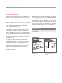
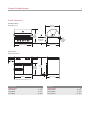
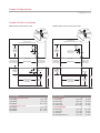
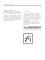
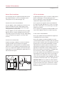
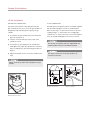
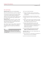
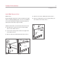
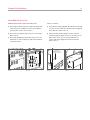
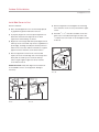
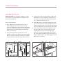
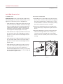
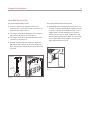
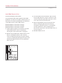
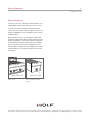
INSTALLATION GUIDE
Outdoor Gas Grills
Contents
Important Note
Wolf Outdoor Gas Grills . . . . . . . . . . . . . . . . . . . . . . . . 3
To ensure the safe and efficient use of Wolf equipment,
please take note of the following types of highlighted
information throughout this guide:
Safety Instructions . . . . . . . . . . . . . . . . . . . . . . . . . . . . 4
Location Considerations . . . . . . . . . . . . . . . . . . . . . . . 5
Outdoor Grill Specifications . . . . . . . . . . . . . . . . . . . . . 6
Outdoor Grill Installation . . . . . . . . . . . . . . . . . . . . . . . 9
Service Information . . . . . . . . . . . . . . . . . . . . . . . . . . . 23
Features and specifications are subject to change at any time
without notice. Visit our website, wolfappliance.com for the
most up-to-date information.
IMPORTANT NOTE: Throughout this guide, dimensions in
parentheses are millimeters unless otherwise specified.
IMPORTANT NOTE highlights information that is
especially important.
CAUTION signals a situation where minor injury or product
damage may occur if instructions are not followed.
WARNING states a hazard that may cause serious injury or
death if precautions are not followed.
Wolf Outdoor Gas Grills
3
wolfappliance.com
Outdoor Grill Installation
Read this entire installation guide prior to installation and
save for the local inspector’s reference. The homeowner
should keep this installation guide for future reference.
The installation of this appliance must conform with local
codes or, in the absence of local codes, either the National
Fuel Gas Code, ANZI Z223.1/NFPA 54, or CAN/CGAB149.1, Natural Gas Installation Code or CAN/CGAB149.2, Propane Installation Code.
The utilization of an external electrical source requires that
when installed, this outdoor cooking gas appliance must
be electrically grounded in accordance with the local
codes or, in the absence of local codes, with the National
Electrical Code, ANSI/NFPA 70, or the Canadian Electrical
Code, CSA C22.1. Keep any electrical supply cord, or the
rotisserie motor cord and the gas supply hose away from
any heated surfaces.
Record the model and serial numbers before installing the
outdoor product. Both numbers are listed on the product
rating plate. For the outdoor grill, the rating plate is
located above the drip tray, behind the logo. The drip tray
must be removed to view the rating plate. For the burner
module and side burner, the rating plate is located under
the bullnose on the right side. Refer to the illustrations
below.
Wolf Outdoor Product
Model Number
Serial Number
This appliance must be installed in accordance with
National Electrical Codes, as well as all state, municipal
and local codes. The correct voltage, frequency and
amperage must be supplied to the appliance from a dedicated, grounded circuit which is protected by a properly
sized circuit breaker or time delay fuse. The proper
voltage, frequency, and amperage ratings are listed on
the product rating plate.
RATING PLATE LOCATION
Outdoor grill.
RATING PLATE LOCATION
Burner module and side
burner.
Safety Instructions
4
IMPORTANT INSTRUCTIONS
• Installation and service must be performed by a
WHAT TO DO IF YOU SMELL GAS:
qualified installer, service agency or the gas supplier.
•
Shut off gas supply to the appliance.
•
Extinguish any open flame.
•
Open hood or remove cover.
•
If odor continues, keep away from the appliance
and immediately call your gas supplier or fire
department.
• Warranty service must be performed by a Wolf
authorized service center.
• Do not store or use gasoline or other flammable
liquids or vapors in the vicinity of this or any other
appliance. An LP gas cylinder not connected for use
shall not be stored in the vicinity of this or any other
appliance.
• In Massachusetts: All gas products must be installed
using a “Massachusetts” licensed plumber or gasfitter. A “T” handle type manual gas valve must be
installed in the gas supply line to this appliance. This
applies to permanently installed natural gas and
propane installations. This does not apply to propane
portable installations using a 20-lb tank.
BEFORE LIGHTING:
• Read instructions before lighting.
• Open hood or remove cover before lighting.
• If ignition does not occur in 5 seconds, turn the
control knob off, wait 5 minutes, and repeat the
lighting procedure.
Location Considerations
5
wolfappliance.com
Locating the Grill
Built-In Applications
IMPORTANT NOTE: This gas appliance is designed and
certified for outdoor use only. Do not operate the outdoor
product inside a building, garage, recreation vehicle or any
enclosed area.
Wolf outdoor grills and the burner module are designed for
easy placement into a built-in enclosure. For outdoor
grills, installation in a combustible enclosure requires an
insulating liner. For the burner module, an insulating liner
is not required. The enclosure should be built according to
specifications for your specific installation found on the
following pages. If the burner module is installed next to
an outdoor grill, a minimum of 2" (51) is required between
units if it is placed to the right of the grill and 12" (305) if
placed to the left.
When choosing an area for the grill, whether a portable or
built-in application, consider exposure to wind, proximity
to traffic paths and length of gas supply line. Keep the gas
supply line as short as possible to reduce pressure drop.
Keep the outdoor product away from windy areas but in a
well ventilated area. Do not obstruct the flow of combustion and ventilation air around the outdoor product. Installation must be level and flat. The supporting deck and
countertop should also be level and flat.
Do not locate outdoor product under overhead
combustible surfaces.
All outdoor grills in a built-in application require a deck to
support the grill. The supporting deck should be level and
flat and able to support 300 lbs (136 kg). A deck is not
required for the burner module.
It is recommended that ventilation holes be provided in the
enclosure so that gas will not become entrapped in the
event of a leak.
MINIMUM CLEARANCES
Portable Applications
Wolf portable grill carts are available to fit all Wolf outdoor
grills and the side burner.
A minimum clearance of 12" (305) from the sides and 12"
(305) from the back of the grill to adjacent vertical
combustible construction must be maintained.
A minimum clearance of 21/2" (64) from the back of the
grill above cooking surface to non-combustible construction is required.
A minimum of 6" (152) clearance to the sides of the grill
above cooking surface to non-combustible construction is
recommended to provide space for the rotisserie motor
and the spit rod. The grill can be installed directly next to
non-combustible construction below the cooking surface.
Outdoor Grill Specifications
6
Overall Dimensions
OUTDOOR GRILL
Model OG36 shown
30" (762)
OVERALL DEPTH
27"
(686)
OVERALL
HEIGHT
2 1/2"
12 1/2" (318)
TO GRILLING
SURFACE
(64)
CLEARANCE
FOR OPEN
HOOD
27 3/4" (705)
OVERALL WIDTH
GRILL CART
Model CART36 shown
12"
(305)
36 1/2"
24" (610)
(927)
TO GRILL
PLATFORM
3" (76)
27 3/4" (705)
WIDTH
MAX DOOR/DRAWER CLEARANCE 22" (559).
Outdoor Grill
OVERALL WIDTH
Model OG30
Model OG36
Model OG42
Grill Cart
W
OVERALL WIDTH
W
30" (762)
36" (914)
42" (1067)
Model CART30
Model CART36
Model CART42
30" (762)
36" (914)
42" (1067)
Outdoor Grill Specifications
7
wolfappliance.com
Outdoor Grill Built-In Installation
NON-COMBUSTIBLE ENCLOSURE
COMBUSTIBLE ENCLOSURE WITH LINER
13/16"
(21)
13/16"
(21)
OPENING
FOR GRILL
OPENING
FOR LINER
COUNTERTOP
OVERHANG
COUNTERTOP
OVERHANG
12" (305) min TO
COMBUSTIBLE REAR SURFACES
2 1/2" (64) min TO
NON-COMBUSTIBLE REAR SURFACES
13"
(330)
24 1/4"
(616)
OPENING
DEPTH
10 3/4"
G
(273) C
L
26"
(660)
OPENING
DEPTH
31/2"
(89)
CL
2 3/4" (70)
TOP VIEW
OPENING WIDTH
11 3/4"
(298)
OPENING
HEIGHT
6" (152) min TO
12" (305) min TO
NON-COMBUSTIBLE
SIDE SURFACES
COMBUSTIBLE
SIDE SURFACES
6"
G
36"
36"
(914)
OPENING WIDTH
FOR ACCESSORY DOORS
OR DRAWERS
OPENING
HEIGHT
COMBUSTIBLE ENCLOSURE
Model OG30
Model OG36
Model OG42
OPENING
HEIGHT
FRONT VIEW
Opening Width
Model OG30
Model OG36
Model OG42
1" (25) min
(914)
FRONT VIEW
NON-COMBUSTIBLE ENCLOSURE
COMBUSTIBLE
SIDE SURFACES
OPENING
HEIGHT
1" (25) min
OPENING WIDTH
FOR ACCESSORY DOORS
OR DRAWERS
12" (305) min TO
OPENING WIDTH
12 5/8" (321)
(152)
4" (102)
(127)
TOP VIEW
6" (152) min TO
NON-COMBUSTIBLE
SIDE SURFACES
5"
KNOCKOUT FOR
GAS SUPPLY
Optional Opening
W
28 1/2" (724)
34 1/2" (876)
40 1/2" (1029)
W
33 1/2" (851)
39 1/2" (1003)
45 1/2" (1156)
ACCESSORY DOORS
18" (457) Single
30" (762) Double
36" (914) Double
42" (1067) Double
ACCESSORY DRAWERS
30" (762) Single
13" (330) Double
13" (330) Triple
30" (762) Double with Door
W
H
16 1/4" (413)
28 1/4" (718)
34 1/4" (870)
40 1/4" (1022)
19" (483)
19" (483)
19" (483)
19" (483)
W
H
27 1/4" (692)
12 1/8" (308)
12 1/8" (308)
29 1/4" (743)
9 3/4" (248)
19" (483)
19" (483)
19" (483)
Outdoor Grill Specifications
8
Overall Dimensions
Built-In Installation (Burner Module)
BURNER MODULE AND SIDE BURNER
NON-COMBUSTIBLE OR COMBUSTIBLE ENCLOSURE
30" (762)
OVERALL DEPTH
9/16"
(14)
OPENING
FOR
MODULE
10 3/4" (273)
OVERALL
HEIGHT
13" (330)
OVERALL
WIDTH
COUNTERTOP
OVERHANG
27 3/4" (705)
TOP VIEW
2 1/2" (64) min TO NON-COMBUSTIBLE
REAR SURFACES
3" (76)
G
24 1/4"
(616)
OPENING
DEPTH
6" (152) min TO
NON-COMBUSTIBLE
SIDE SURFACES
10" (254)
OPENING
HEIGHT
12"
(305)
OPENING
WIDTH
G
6" (152) min TO
NON-COMBUSTIBLE
SIDE SURFACES
8"
(203)
7"
(178)
36"
(914)
Outdoor Grill Installation
9
wolfappliance.com
Electrical Requirements
INSTALL THE POWER TRANSFORMER
Wolf outdoor grills and the burner module have a power
transformer for the lights and igniters which is concealed
in a stainless steel box with an attached power supply
cord.
BUILT-IN APPLICATION: Secure the transformer box in a
dry location, away from the grill firebox and excessive heat
area, but within 2' (.6 m) of the right rear grill opening.
CART APPLICATION: Two mounting screws are provided
at the bottom right rear corner of the cart to secure the
transformer box. If a side burner is being attached to a
cart, it will utilize the same transformer as the gas grill.
IMPORTANT NOTE: Do not install the transformer box
inside the insulating liner. The transformer box must be
secured away from excessive heat and in a dry location.
Make the transformer connections to the wire harness
located at the right rear of the grill to the harness of the
transformer box.
Plug the power cord from the transformer into a properly
grounded GFCI 120 V AC outlet. The outlet must be
located within 6' (1.8 m) of the transformer.
ROTISSERIE MOTOR
The rotisserie motor requires a GFCI 120 V AC electrical
supply. The 9' (2.7 m) power cord on the motor is
equipped with a 3-prong grounded plug for protection
against shock hazard.
IMPORTANT NOTE: The burner module must be installed
at least 12" (305) from the rotisserie motor.
ELECTRICAL GROUNDING: The outdoor gas grill is
equipped with a 3-prong grounding plug for protection
against shock hazard. It should be plugged directly into
a properly grounded 3-prong outlet. Do not cut or
remove the grounding prong from the plug.
DO NOT use an extension cord or two-prong adapter.
Outdoor Grill Installation
10
Gas Supply Requirements
IMPORTANT NOTE: The outdoor product must be
connected to a regulated gas supply by a qualified technician and in accordance with local codes and ordinances.
Each appliance is set and tested at the factory for the type
of gas supply to be used. Identify the type of gas, either
natural gas or LP gas, and make sure that the type of gas
specified on the product rating plate matches the gas
being supplied to the outdoor product. Refer to page 3 for
location of the rating plate.
GAS SUPPLY LINE
Connect the outdoor product to the gas supply line. The
gas supply line must be of adequate size to properly
service all gas appliances. Wolf recommends the use of a
minimum 1/2" (13) I.D. commercial type flex hose from the
gas supply line to the outdoor product connection. The
units will operate on 1/2" (13) pipe to a maximum run of 30'
(9 m). All plumbing to the flex hose must be 3/4" (19)
minimum I.D. pipe.
IMPORTANT NOTE: For complete gas shutdown, an
external gas shut-off valve must be located near the
outdoor product in an accessible location. Refer to the
illustration below.
Ensure that the gas supply line does not come in
contact with any hot surface of the outdoor product.
OPEN POSITION
TO APPLIANCE
GAS SUPPLY
LINE
Gas supply shut-off valve.
Outdoor Grill Installation
11
wolfappliance.com
Natural Gas Installations
LP Gas Installations
The natural gas pressure regulator provided with natural
gas outdoor products is set for 4" (10 mb) WC (water
column) and is for use with natural gas only.
LP (liquefied petroleum) gas is sometimes called propane,
butane or bottled gas. It is a flammable gas which
becomes liquid when stored under high pressure inside a
cylinder and it vaporizes when released.
NATURAL GAS SAFETY REQUIREMENT
The LP gas pressure regulator and hose provided with
LP outdoor gas grills and SB13-LP is set for 11" (27 mb)
WC (water column) and is for use with LP gas only and a
20-lb LP gas cylinder.
This gas appliance and its individual shut-off valve must
be disconnected from the gas supply piping system
during any pressure testing of that system at test pressures greater than .5 psi (3.5 kPa).
This gas appliance must be isolated from the gas supply
piping system by closing its individual manual shut-off
valve during any pressure testing of the gas supply piping
system at test pressures equal to or less than .5 psi
(3.5 kPa).
NATURAL GAS CONNECTION
A typical natural gas installation is shown in the illustrations below. Make sure that the pressure regulator
supplied with the outdoor product is used and installed
with the arrow on the regulator pointing towards the unit.
Do not use a replacement regulator other than that specified by Wolf. Use only gas piping that is approved for use
with natural and LP gases.
REGULATOR
REAR GAS
CONNECTION
BOTTOM GAS
CONNECTION
SHUT-OFF
VALVE
Natural gas connection.
TO GRILL
LP GAS SAFETY REQUIREMENT
The LP gas cylinder must be provided with an approved
overfilling preventive device (OPD).
Any LP gas cylinder used with this appliance must be
constructed and marked in accordance with the specifications for LP gas cylinders of the U.S. Department of Transportation (D.O.T.) or the National Standards of Canada
CAN/CSA-B339, Cylinders, Spheres and Tubes for the
Transportation of Dangerous Goods, and Commission, as
applicable. Provided with a listed overfilling prevention
device and a cylinder connection device compatible with
the connection for outdoor cooking appliances.
The LP gas cylinder must be provided with a shut-off valve
terminating in the cylinder valve outlet. It must include a
collar to protect the cylinder valve. The cylinder supply
system must be arranged for vapor withdrawal. Do not use
a cylinder that is dented, rusted or has a damaged valve.
ADAPTER
VENT
The LP gas pressure regulator provided with BM13-LP is
set for 10" (25 mb) WC and is for use with LP gas only.
CLOSE
NIPPLE
FROM GAS
SUPPLY
REGULATOR
Natural gas regulator.
IMPORTANT NOTE: Do not operate the outdoor product
indoors or in any enclosed area. When not in use, the gas
must be turned off at the LP gas cylinder. If the outdoor
product is to be stored indoors, disconnect the cylinder
and leave it outdoors.
Outdoor Grill Installation
12
LP Gas Installations
PORTABLE LP CONNECTION
LP GAS CONNECTION
One of the many features of the Wolf grill cart is the
pull-out shelf for easy access to the LP gas cylinder. It is
designed to hold a 20-lb (5 gallon capacity) LP gas
cylinder.
Install the pressure regulator and hose assembly supplied
with the outdoor product as shown in the illustrations
below. Connect the 3/8" flare end of the hose to the unit
coupling using a 3/4" open wrench. Do not apply pipe
sealant to the 3/8" flare connection. Connect the regulator
to the LP cylinder hand-tighten, do not use a wrench.
1) To install the LP gas cylinder, pull out the shelf and
place the cylinder on it.
2) Check to ensure that the gas valve on top of the
cylinder is closed.
3) Connect the LP gas regulator to the cylinder and
hand-tighten only. Open the cylinder valve. Check for
leaks according to the gas leak testing procedure on
page 13.
4) Tighten the thumb screw to secure the cylinder to the
shelf.
The LP pressure regulator and hose supplied with the
outdoor product must be used without alteration.
Do not place more than one LP gas cylinder in an
enclosure at one time.
Always check for gas leaks after changing the LP gas
cylinder.
REGULATOR
COUPLING NUT
GRILL
COUPLING
TO GRILL
REGULATOR
VENT
HOSE
ASSEMBLY
VENT
LP GAS
CYLINDER
VENT
LP gas connection.
Grill cart pull-out shelf.
LP GAS
CYLINDER
LP gas regulator.
Outdoor Grill Installation
13
wolfappliance.com
Gas Leak Testing
IMPORTANT NOTE: Never use the outdoor product
without first testing the gas line connections for gas leaks.
Perform a gas leak test each time the LP gas cylinder is
connected to the regulator and any time part of the gas
system is disconnected or replaced. This applies to
natural gas as well as LP gas. Perform a leak test at least
once each year whether the LP gas cylinder has been
disconnected or not.
IMPORTANT NOTE: To prevent fire or explosion hazard,
do not smoke or permit sources of ignition in the area
while performing a leak test. Perform the gas leak test
outdoors in a well ventilated area.
Have a dealer check the LP gas cylinder for deterioration
when the tank is filled in accordance with regulations.
Immediately replace the cylinder if any deterioration is
found.
DO NOT use an open flame to check for gas leaks.
Use of an open flame could result in a fire, explosion
and bodily harm.
GAS LEAK TESTING PROCEDURE
1) Prepare a leak testing solution of soapy water by
combining a mixture of half liquid soap and half water
in a spray bottle.
2) Verify that all control knobs are in the OFF position.
3) Turn the cylinder valve knob counterclockwise one turn
to open.
4) Apply the leak testing solution by spraying on the pipe
joints, fittings and hose. Bubbles in the soap and water
solution indicate that a gas leak is present.
5) Stop the leak by tightening the loose joint or by
replacing the faulty part with a replacement part
recommended by the Wolf. Do not attempt to repair the
cylinder valve if it should become damaged. The
cylinder must be replaced.
6) If you are unable to stop the leak, shut off the gas
supply at the cylinder valve. Remove the LP gas
cylinder. Call a Wolf authorized service center.
IMPORTANT NOTE: Do not use the outdoor product until
the leak has been fixed.
7) Push in and turn any control knob to the ON position to
release pressure in the hose and manifold.
8) Turn the control knob to the OFF position.
Outdoor Grill Installation
14
Outdoor Grill Assembly
Install Grill to Cart
Wolf outdoor products are produced fully assembled and
tested in the factory and require no major assembly in the
field. For the purpose of safe shipping and transit, some
parts such as the briquette trays, warming rack and rotisserie components are wrapped inside the grill and require
minor assembly.
Wolf portable grill carts are available to fit all Wolf outdoor
grill models.
Remove all packaging materials, labels and protective
plastic film from the grill.
IMPORTANT NOTE: Do not leave the grill or grill cart in the
sun with the protective plastic film on for an extended
period or it may be difficult to remove.
Verify that all grill components are included: control knobs,
hexagonal grates, large and small briquette tray assemblies, rotisserie motor with bracket, spit rod and meat
forks, natural gas or LP gas regulator, basting pan,
warming rack and smoker box assembly.
TO INSTALL BRIQUETTE TRAYS
1) Place the briquette trays into the grill above the
burners with the flash tube at the front as shown in the
illustration below.
2) Place the hexagonal grates directly above the briquette
trays and make sure the square openings on the grates
are at the front.
FLASH TUBE
Flash tube position.
1) In a cart application, two mounting screws with nuts
are provided at the bottom right rear corner of the cart
for the transformer. If not provided, drill two holes
using the transformer box as a template. Install the
transformer box.
2) Remove front mounting screws from cart. Place grill
onto cart. Leave enough room at the back right rear of
the cart to make connection to the transformer.
3) Once connection to the transformer is made, slide the
grill back until it is fully engaged with the cart.
4) With grill in position, secure grill to cart with four
screws provided. Mounting holes in the upper back
corners of the grill will align with holes in the cart.
Secure with two screws. Remove the drip tray. Install
two screws through side mounting holes below the grill
front panel and into the cart.
Outdoor Grill Installation
15
wolfappliance.com
Install Side Burner to Cart
MODEL SB13
4) Remove rear screws and bracket. Refer to illus 3.
Wolf model SB13 side burner can be installed on the right
side of any Wolf portable grill cart. For ease of installation,
it is recommended that installation be performed by two
technicians. Follow these steps to install:
5) Remove cart plug from access hole by pushing out
from inside of cart. Refer to illus 3.
REMOVE SIDE SHELF (IF INSTALLED) AND CART PLUG
1) Lift side shelf so lower front screw is exposed and
remove screw. Refer to illus 1.
2) Lower shelf to down position and remove upper front
screw. Refer to illus 2.
REAR
BRACKET
CART PLUG
3) Remove side shelf and front bracket. Refer to illus 2.
Illus 3.
UPPER
SCREW
FRONT
BRACKET
LOWER SCREW
Illus 1.
Illus 2.
SIDE SHELF
Outdoor Grill Installation
16
Install Side Burner to Cart
REMOVE REAR PANEL, DOOR AND DRIP TRAY
INSTALL SHROUD
1) Removing rear panel and door of grill cart will provide
easier access for installation. Remove rear panel by
removing four screws. Refer to illus 4.
1) Push plastic bushing supplied with side burner through
access hole from inside cart. Bushing must be applied
in this direction. Refer to illus 6.
2) Remove door by depressing rear lever on each hinge.
Refer to illus 5.
2) Hang shroud by hand-starting four 10-32 machine
screws through the upper slots of the shroud, into the
upper holes of the cart. Do not fully tighten these
screws until proper alignment has been achieved.
Refer to illus 7.
3) Removing grill drip tray will provide easier access for
installation. To remove drip tray, slide forward and lift
out. Refer to illus 5.
BUSHING
(INSERT THROUGH
INSIDE OF CART)
DRIP TRAY
SCREWS
SCREWS
SCREWS
SCREWS
REAR LEVER
Illus 4.
Illus 5.
Illus 6.
Illus 7.
Outdoor Grill Installation
17
wolfappliance.com
Install Side Burner to Cart
INSTALL SHROUD
4) Place shroud alignment tool as shown with lip placed
in gap between grill and side burner shroud.
5) To properly align front of shroud, push alignment tool
back until center block of alignment tool is flush
against front vertical flange of shroud.
8) Remove alignment tool and tighten two remaining
10-32 machine screws to slots just below the upper
screws.
9) Install two 5/16 x 3/8 hex drive shoulder screws into
lower holes of shroud and through cart. Place two
1/4–20 hex nuts from inside of cart and tighten. Refer
to illus 10.
6) Align front of shroud (up and down) with alignment tool
until top of tool is flush with top surface of grill bullnose
(front ledge), and align shroud (front to back) with tool
until front of tool is flush with front of bullnose. Tighten
upper front 10-32 machine screw. Refer to illus 8.
7) Remove alignment tool from front of shroud and
replace at rear of shroud. Align rear of shroud (up and
down) with tool until top of tool is flush with top
surface of grill. Tighten upper rear 10-32 machine
screw. Refer to illus 9.
SHOULDER
SCREWS
HEX NUT
(INSIDE CART)
IMPORTANT NOTE: Verify with alignment tool that front
of shroud did not move out of alignment. Realign if
necessary.
Illus 10.
ALIGNMENT
TOOL
SURFACES
FLUSH
Illus 8.
UPPER
SCREW
SURFACES
FLUSH
UPPER
SCREW
Illus 9.
ALIGNMENT
TOOL
Outdoor Grill Installation
18
Install Side Burner to Cart
IMPORTANT NOTE: For natural gas installations, the gas
line connection must be made before installing the side
burner. Refer to page 20.
3) Compress bar clamp until hole in bullnose aligns with
threaded hole in shroud. Alignment and placement of
this screw is very important to alignment and squareness of side burner. Refer to illus 13.
INSTALL SIDE BURNER
4) Attach side burner to shroud by first placing 8-32 hex
cap screw into right side of front underside of bullnose
and into shroud as shown. Then, place the left side hex
cap screw. Tighten both screws and remove bar clamp.
1) Place side burner into shroud as shown in illus 11.
Guide flexible gas line and wire harness into cart
access hole. Alignment of unit should be verified at this
point, prior to attaching side burner to shroud. Refer to
alignment tips on the following page if desired alignment is not achieved.
2) Using a bar clamp with protected ends to avoid
damage to stainless steel, place bar clamp just behind
bullnose on fire box and under shroud. Do not include
any part of bullnose within bar clamp. Refer to illus 12.
5) At rear of unit, push side burner toward grill to establish proper gap at rear. Loosen rear grill cart screws
and shift grill if necessary to achieve proper gap.
Attach two 8-18 pan head (sharp tip) screws into the
rear of the side burner and shroud as shown in illus 14.
Refer to alignment tips on the following page if desired
alignment is not achieved.
REAR
SCREWS
HOLES
ALIGN
ACCESS HOLE
Illus 11.
Illus 12.
Illus 13.
Illus 14.
Outdoor Grill Installation
19
wolfappliance.com
Install Side Burner to Cart
ALIGNMENT TIPS
ELECTRICAL CONNECTION
IMPORTANT NOTE: There can be minimal variation in the
manufacturing process of these outdoor products, so the
alignment tool will not be precise in all applications.
1) Depending on the serial number of the grill, there may
be one or two connectors near the front of the grill just
above the manifold. Refer to auxiliary harness section
for serial numbers. Locate the connector(s) by looking
above the manifold near the front of the grill.
• If side burner does not align front to back, remove unit,
loosen shroud screws and bolts, and check with alignment tool. Nudge side burner forward or backward to
establish proper alignment. Verify that alignment up
and down is still accurate. Tighten screws and bolts.
Check alignment and adjust again, if necessary.
• If side burner does not align up and down near front of
unit, loosen hex cap screws under bullnose, lift up or
push down on unit to achieve desired alignment and
tighten screws.
2) Remove the unpopulated connector housing(s) from
the wire harness(es) coming from the grill as shown in
illus 15.
3) Attach the appropriate connector housing(s) from the
side burner to the grill. Refer to illus 16. If only one
connector is found on the grill, refer to the auxiliary
harness section for assembly of the second connector
housing.
• If side burner does not align up and down near rear of
unit, loosen pan head screws at rear of unit, lift up or
push down on unit to achieve desired alignment and
tighten screws.
UNPOPULATED
CONNECTORS
• If side burner does not align side to side, loosen hex
cap screws under bullnose and pan head screws at
rear of unit. Push in or pull out on side burner to
achieve desired alignment. If necessary, loosen screws
at rear of grill where grill attaches to cart, and align grill
with side burner. Tighten screws.
Illus 15.
Illus 16.
Outdoor Grill Installation
20
Install Side Burner to Cart
GAS LINE CONNECTION (LP GAS)
GAS LINE CONNECTION (NATURAL GAS)
1) Connect 2-stage LP gas regulator to flare tee at
location shown. Connect flare swivel connector to one
end of flare tee. Refer to illus 17.
1) Split high pressure natural gas line into two lines, one
to attach to outdoor grill natural gas regulator, and one
to attach to side burner via flexible line and 1/2" NPT
adapter. Make sure that flexible gas line is placed
through cart access hole. Attach flexible line to side
burner regulator at pipe elbow. Elbow may be rotated
to face downward for larger adapters. Do not rotate
elbow upward. Refer to illus 19.
2) Connect this assembly to flexible gas line coming into
grill cart from side burner as shown illus 18.
3) Connect this assembly to grill manifold at flare swivel
connector as shown illus 18.
4) Reinstall rear panel and door of grill cart. Reposition
grill drip tray. Place burner cap on burner head, place
grate on burner pan, and affix knob to bezel with bezel
nylon liner.
FLARE TEE
FLEXIBLE
GAS LINE
FLARE
SWIVEL
GRILL
MANIFOLD
LP GAS
REGULATOR
Illus 17.
Illus 19.
Illus 18.
Outdoor Grill Installation
21
wolfappliance.com
Install Side Burner to Cart
AUXILIARY WIRING (IF APPLICABLE)
If you purchased a Wolf outdoor grill with serial number
listed below, you will have received an auxiliary harness. If
this harness has not been provided with your side burner,
contact Wolf customer service 800-332-9513.
Model OG30 before serial number 11364339.
Model OG36 before serial number 11363946.
Model OG42 before serial number 11363911.
1) If still installed, rear panel of cart must be removed to
install auxiliary harness. Remove rear panel by
removing four screws. Refer to illus 4 on page 16.
2) With wire ties provided, attach auxiliary harness to fire
box fin or existing wire harness. 4-pin connector
cluster should be placed facing rear of grill, and 2-pin
connector should be placed facing front. Harness must
be tied down tightly and must not touch grill fire box.
Refer to illus 20.
Illus 20.
3) If connected, disconnect transformer 4-pin connector
at rear of grill. Attach one of 4-pin connectors to 4-pin
connector attached to grill. Attach other 4-pin connector to 4-pin connector from transformer.
4) Remove unpopulated connector housing from wire
harness coming from grill. Insert each connector
housing from side burner harness to corresponding
housing on grill harness and on auxiliary harness.
There are two connections to be made. Refer to illus 15
and 16 on page 19.
5) Reinstall rear panel of cart.
Outdoor Grill Installation
22
Installation Checklist
Troubleshooting
IMPORTANT NOTE: To ensure a safe and proper installation, the following checklist should be completed by the
installer to ensure that no part of the installation has been
overlooked.
IMPORTANT NOTE: If the outdoor gas grill does not
operate properly, follow these troubleshooting steps:
Any questions or problems about the installation should
be directed to your authorized Wolf dealer or Wolf
customer service at 800-332-9513. You can also visit our
website at wolfappliance.com.
All packaging material has been removed.
Specified clearances to combustible materials have
been maintained.
All burners light properly, individually and with adjacent
burners lit.
All flames appear normal.
• Verify that gas is being supplied to the grill.
• Check the gas supply and electrical connections to
ensure that the installation has been completed
correctly.
• Check that control knobs are turned to the ON position
and held in to active the igniters.
• Follow troubleshooting procedures as described in the
Wolf outdoor gas grills use & care guide.
• If the outdoor grill still does not work, contact a Wolf
authorized service center. Do not attempt to repair the
grill yourself. Wolf is not responsible for service
required to correct a faulty installation.
The drip tray slides freely and is properly placed.
The correct pressure regulator is connected for natural
or LP gas and set for 4" (10 mb) WC for natural gas or
11" (27 mb) WC for LP gas (10" WC for BM13-LP).
The LP gas cylinder is in an upright position and the
hose is not kinked.
The outdoor product has been tested and is free of any
gas leak.
The homeowner has been informed of the gas supply
shut-off valve location.
Be sure to disconnect the electrical and gas supply
before servicing.
Service Information
23
wolfappliance.com
Service Information
If service is necessary, maintain the quality built into your
outdoor grill by calling a Wolf authorized service center.
To obtain the name and number of a Wolf authorized
service center, check the contact & support section of our
website, wolfappliance.com or call Wolf customer service
at 800-332-9513.
When calling for service, you will need the outdoor grill
model and serial numbers. Both numbers are listed on the
product rating plate. For the outdoor grill, the rating plate
is located above the drip tray, behind the logo. The drip
tray must be removed to view the rating plate. For the
burner module and side burner, the rating plate is located
under the bullnose on the right side. Refer to the illustrations below.
RATING PLATE LOCATION
Outdoor grill.
RATING PLATE LOCATION
Burner module and side
burner.
The information and images in this guide are the copyright property of Wolf Appliance, Inc. Neither this guide nor any information or images contained
herein may be copied or used in whole or in part without the express written permission of Wolf Appliance, Inc. ©Wolf Appliance, Inc. all rights reserved.
WOLF APPLIANCE, INC.
P. O. BOX 44848 MADISON, WI 53744
815955 REV-A
3/ 2010
WOLFAPPLIANCE.COM
800.332.9513