1
Doc. no. LEC-OM02401
PRODUCT NAME
AC Servo Motor Controller
MODEL/ Series
LECSB Series
LECSB□-□ Series / Controller
1. Safety Instructions
These safety instructions are intended to prevent hazardous situations and/or equipment damage.
These instructions indicate the level of potential hazard with the labels of “Caution,” “Warning” or “Danger.”
They are all important notes for safety and must be followed in addition to International Standards (ISO/IEC),
Japan Industrial Standards (JIS)*1) and other safety regulations*2).
*1) ISO 4414: Pneumatic fluid power -- General rules relating to systems
ISO 4413: Hydraulic fluid power -- General rules relating to systems
IEC 60204-1: Safety of machinery -- Electrical equipment of machines (Part 1: General requirements)
ISO 10218-1992: Manipulating industrial robots -- Safety
JIS B 8370: General rules for pneumatic equipment.
JIS B 8361: General rules for hydraulic equipment.
JIS B 9960-1: Safety of machinery – Electrical equipment for machines. (Part 1: General requirements)
JIS B 8433-1993: Manipulating industrial robots - Safety. etc.
*2) Labor Safety and Sanitation Law, etc.
Caution
Caution indicates a hazard with a low level of risk which, if not avoided, could result in minor or
Warning
Warning indicates a hazard with a medium level of risk which, if not avoided, could result in death
Danger
Danger indicates a hazard with a high level of risk which, if not avoided, will result in death or
moderate injury.
or serious injury.
serious injury.
Warning
1. The compatibility of the product is the responsibility of the person who designs the equipment or
decides its specifications.
Since the product specified here is used under various operating conditions, its compatibility with specific
equipment must be decided by the person who designs the equipment or decides its specifications based on
necessary analysis and test results.
The expected performance and safety assurance of the equipment will be the responsibility of the person who
has determined its compatibility with the product.
This person should also continuously review all specifications of the product referring to its latest catalog
information, with a view to giving due consideration to any possibility of equipment failure when configuring the
equipment.
2. Only personnel with appropriate training should operate machinery and equipment.
The product specified here may become unsafe if handled incorrectly.
The assembly, operation and maintenance of machines or equipment including our products must be
performed by an operator who is appropriately trained and experienced.
3. Do not service or attempt to remove product and machinery/equipment until safety is confirmed.
The inspection and maintenance of machinery/equipment should only be performed after measures to prevent
falling or runaway of the driven objects have been confirmed.
When the product is to be removed, confirm that the safety measures as mentioned above are implemented
and the power from any appropriate source is cut, and read and understand the specific product precautions of
all relevant products carefully.
Before machinery/equipment is restarted, take measures to prevent unexpected operation and malfunction.
4. Contact SMC beforehand and take special consideration of safety measures if the product is to be
used in any of the following conditions.
1) Conditions and environments outside of the given specifications, or use outdoors or in a place exposed to
direct sunlight.
2) Installation on equipment in conjunction with atomic energy, railways, air navigation, space, shipping,
vehicles, military, medical treatment, combustion and recreation, or equipment in contact with food and
beverages, emergency stop circuits, clutch and brake circuits in press applications, safety equipment or other
applications unsuitable for the standard specifications described in the product catalog.
3) An application which could have negative effects on people, property, or animals requiring special safety
analysis.
4) Use in an interlock circuit, which requires the provision of double interlock for possible failure by using a
mechanical protective function, and periodical checks to confirm proper operation.
A- 1
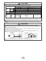
Note that the CAUTION level may lead to a serious consequence according to conditions. Please follow the
instructions of both levels because they are important to personnel safety.
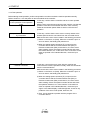
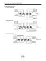
What must not be done and what must be done are indicated by the following diagrammatic symbols.
Prohibition
Indicates what must not be done. For example, "No Fire" is indicated by
Compulsion
Indicates what must be done. For example, grounding is indicated by
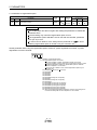
In this Instruction Manual, instructions at a lower level than the above, instructions for other functions, and so on
are classified into "POINT".
After reading this installation guide, always keep it accessible to the operator.
A- 2
LECSB□-□ Series / Controller
1. Safety Instructions
Caution
The product is provided for use in manufacturing industries.
The product herein described is basically provided for peaceful use in manufacturing industries.
If considering using the product in other industries, consult SMC beforehand and exchange specifications or a
contract if necessary.
If anything is unclear, contact your nearest sales branch.
Limited warranty and Disclaimer/Compliance Requirements
The product used is subject to the following “Limited warranty and Disclaimer” and “Compliance
Requirements”.
Read and accept them before using the product.
Limited warranty and Disclaimer
The warranty period of the product is 1 year in service or 1.5 years after the product is delivered.*3)
Also, the product may have specified durability, running distance or replacement parts. Please consult
your nearest sales branch.
For any failure or damage reported within the warranty period which is clearly our responsibility, a
replacement product or necessary parts will be provided.
This limited warranty applies only to our product independently, and not to any other damage incurred
due to the failure of the product.
Prior to using SMC products, please read and understand the warranty terms and disclaimers noted in
the specified catalog for the particular products.
*3) Vacuum pads are excluded from this 1 year warranty.
A vacuum pad is a consumable part, so it is warranted for a year after it is delivered.
Also, even within the warranty period, the wear of a product due to the use of the vacuum pad or
failure due to the deterioration of rubber material are not covered by the limited warranty.
Compliance Requirements
When the product is exported, strictly follow the laws required by the Ministry of Economy, Trade and Industry
(Foreign Exchange and Foreign Trade Control Law).
A- 3
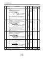
1. To prevent electric shock, note the following
WARNING
Before wiring or inspection, turn off the power and wait for 15 minutes or more (20 minutes or for drive unit
30kW or more) until the charge lamp turns off. Then, confirm that the voltage between P( ) and N( )
(L and L for drive unit 30kW or more) is safe with a voltage tester and others. Otherwise, an electric
shock may occur. In addition, always confirm from the front of the controller (converter unit), whether the
charge lamp is off or not.
Connect the converter unit, controller (drive unit) and servo motor to ground.
Any person who is involved in wiring and inspection should be fully competent to do the work.
Do not attempt to wire the converter unit, controller (drive unit) and servo motor until they have been
installed. Otherwise, you may get an electric shock.
Operate the switches with dry hand to prevent an electric shock.
The cables should not be damaged, stressed, loaded, or pinched. Otherwise, you may get an electric
shock.
During power-on or operation, do not open the front cover. You may get an electric shock.
Do not operate the converter unit and controller (drive unit) with the front cover removed. High-voltage
terminals and charging area are exposed and you may get an electric shock.
Except for wiring or periodic inspection, do not remove the front cover even if the power is off. The
controller (drive unit) is charged and you may get an electric shock.
2. To prevent fire, note the following
CAUTION
Install the converter unit, controller (drive unit), servo motor and regenerative resistor on incombustible
material. Installing them directly or close to combustibles will lead to a fire.
Always connect a magnetic contactor between the main circuit power supply and L1, L2, and L3 of the
converter unit, controller (drive unit), and configure the wiring to be able to shut down the power supply on
the side of the converter unit, controller (drive unit) power supply. If a magnetic contactor is not connected,
continuous flow of a large current may cause a fire when the converter unit, controller (drive unit)
malfunctions.
When a regenerative resistor is used, use an alarm signal to switch main power off. Otherwise, a
regenerative transistor fault or the like may overheat the regenerative resistor, causing a fire.
Provide adequate protection to prevent screws and other conductive matter, oil and other combustible
matter from entering the converter unit, controller (drive unit), and servo motor.
Always connect a no-fuse breaker to the power supply of the controller (converter unit).
A- 4
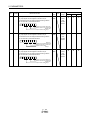
3. To prevent injury, note the follow
CAUTION
Only the voltage specified in the Instruction Manual should be applied to each terminal, Otherwise, a burst,
damage, etc. may occur.
Connect the terminals correctly to prevent a burst, damage, etc.
Ensure that polarity ( , ) is correct. Otherwise, a burst, damage, etc. may occur.
Take safety measures, e.g. provide covers, to prevent accidental contact of hands and parts (cables, etc.)
with the converter unit and controller (drive unit) heat sink, regenerative resistor, servo motor, etc. since
they may be hot while power is on or for some time after power-off. Their temperatures may be high and
you may get burnt or a parts may damaged.
During operation, never touch the rotating parts of the servo motor. Doing so can cause injury.
4. Additional instructions
The following instructions should also be fully noted. Incorrect handling may cause a fault, injury, electric shock,
etc.
(1) Transportation and installation
CAUTION
Transport the products correctly according to their mass.
Stacking in excess of the specified number of products is not allowed.
Do not carry the servo motor by the cables, shaft or encoder.
Do not hold the front cover to transport the converter unit and controller (drive unit). The converter unit and
controller (drive unit) may drop.
Install the converter unit and controller (drive unit) in a load-bearing place in accordance with the
Instruction Manual.
Do not climb or stand on servo equipment. Do not put heavy objects on equipment.
The converter unit, controller (drive unit), and servo motor must be installed in the specified direction.
Leave specified clearances between the converter unit, controller (drive unit), and control enclosure walls
or other equipment.
Do not install or operate the converter unit, controller (drive unit), and servo motor which has been
damaged or has any parts missing.
Do not block the intake and exhaust areas of the converter unit, controller (drive unit) and servo motor
which has a cooling fan. Doing so may cause faults.
Do not drop or strike converter unit, controller (drive unit), or servo motor. Isolate from all impact loads.
Securely attach the servo motor to the machine. If attach insecurely, the servo motor may come off during
operation.
The servo motor with reduction gear must be installed in the specified direction to prevent oil leakage.
Take safety measures, e.g. provide covers, to prevent accidental access to the rotating parts of the servo
motor during operation.
Never hit the servo motor or shaft, especially when coupling the servo motor to the machine. The encoder
may become faulty.
Do not subject the servo motor shaft to more than the permissible load. Otherwise, the shaft may break.
A- 5
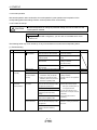
CAUTION
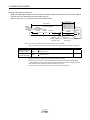
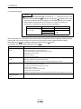
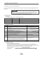
When you keep or use it, please fulfill the following environmental conditions.
Environmental conditions
Item
Ambient
temperature
Ambient
humidity
Converter unit controller (drive unit)
In
operation
In storage
Servo motor
[
]
0 to 55 (non-freezing)
0 to 40 (non-freezing)
[
]
32 to 131 (non-freezing)
32 to 104 (non-freezing)
[
]
20 to 65 (non-freezing)
[
]
4 to 149 (non-freezing)
15 to 70 (non-freezing)
5 to 158 (non-freezing)
In operation
90%RH or less (non-condensing)
In storage
90%RH or less (non-condensing)
80%RH or less (non-condensing)
Ambience
Indoors (no direct sunlight) Free from corrosive gas, flammable gas, oil mist, dust and dirt
Altitude
Max. 1000m (3280 ft) above sea level
LECS□□-S5
(Note)
Vibration
5.9 or less at 10 to
55Hz (directions of
X, Y and Z axes)
2
[m/s ]
LECS□□-S7
X, Y: 49 m/s2
LECS□□-S8
series
Note. Except the servo motor with reduction gear.
When the equipment has been stored for an extended period of time, contact your local sales office.
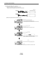
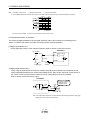
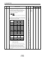
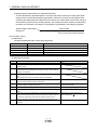
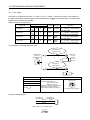
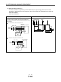
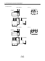
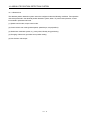
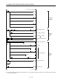
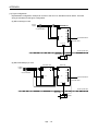
(2) Wiring
CAUTION
Wire the equipment correctly and securely. Otherwise, the servo motor may operate unexpectedly.
Do not install a power capacitor, surge absorber or radio noise filter (FR-BIF-(H) option) between the servo
motor and controller (drive unit).
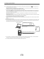
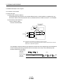
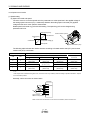
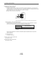
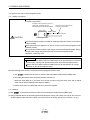
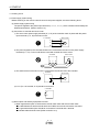
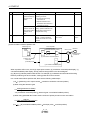
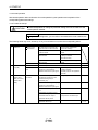
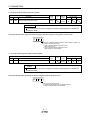
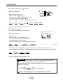
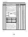
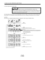
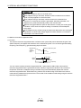
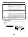
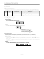
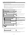
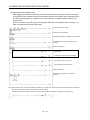
Connect the wires to the correct phase terminals (U, V, W) of the controller (drive unit) and servo motor.
Not doing so may cause unexpected operation.
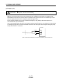
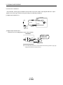
Connect the servo motor power terminal (U, V, W) to the servo motor power input terminal (U, V, W)
directly. Do not let a magnetic contactor, etc. intervene.
Servo amplifier
(drive unit)
U
V
W
Servo motor
U
V
Servo amplifier
(drive unit)
U
V
M
W
W
Servo motor
U
V
W
Do not connect AC power directly to the servo motor. Otherwise, a fault may occur.
A- 6
M
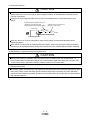
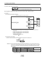
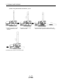
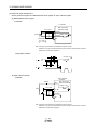
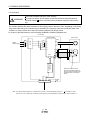
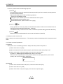
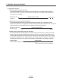
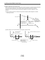
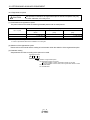
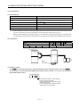
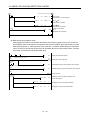
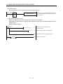
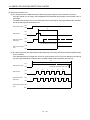
CAUTION
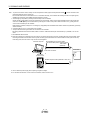
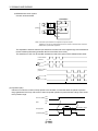
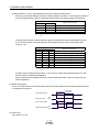
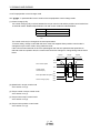
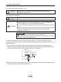
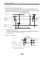
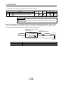
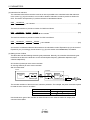
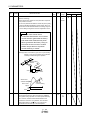
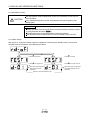
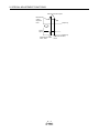
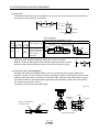
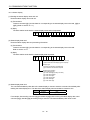
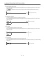
The surge absorbing diode installed to the DC relay for control output should be fitted in the specified
direction. Otherwise, the emergency stop and other protective circuits may not operate.
Servo amplifier
(drive unit)
Servo amplifier
(drive unit)
24VDC
24VDC
DOCOM
Control output
signal
DICOM
DOCOM
Control output
signal
DICOM
RA
For sink output interface
RA
For source output interface
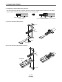
When the cable is not tightened enough to the terminal block (connector), the cable or terminal block
(connector) may generate heat because of the poor contact. Be sure to tighten the cable with specified
torque.
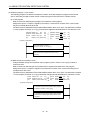
(3) Test run adjustment
CAUTION
Before operation, check the parameter settings. Improper settings may cause some machines to perform
unexpected operation.
The parameter settings must not be changed excessively. Operation will be insatiable.
(4) Usage
CAUTION
Provide an external emergency stop circuit to ensure that operation can be stopped and power switched
off immediately.
Any person who is involved in disassembly and repair should be fully competent to do the work.
Before resetting an alarm, make sure that the run signal of the controller (drive unit) is off to prevent an
accident. A sudden restart is made if an alarm is reset with the run signal on.
Do not modify the equipment.
Use a noise filter, etc. to minimize the influence of electromagnetic interference, which may be caused by
electronic equipment used near the converter unit and controller (drive unit).
Burning or breaking a converter unit and controller (drive unit) may cause a toxic gas. Do not burn or break
a converter unit and controller (drive unit).
Use the converter unit and controller (drive unit) with the specified servo motor.
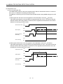
The electromagnetic brake on the servo motor is designed to hold the motor shaft and should not be used
for ordinary braking.
For such reasons as service life and mechanical structure (e.g. where a ball screw and the servo motor are
coupled via a timing belt), the electromagnetic brake may not hold the motor shaft. To ensure safety, install
a stopper on the machine side.
A- 7
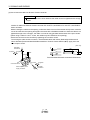
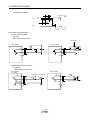
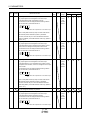
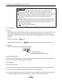
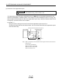
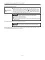
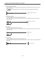
(5) Corrective actions
CAUTION
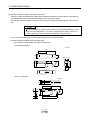
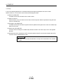
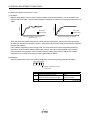
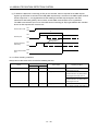
When it is assumed that a hazardous condition may take place at the occur due to a power failure or a
product fault, use a servo motor with an electromagnetic brake or an external brake mechanism for the
purpose of prevention.
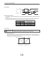
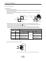
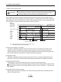
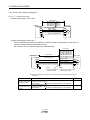
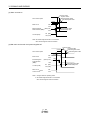
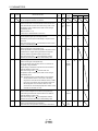
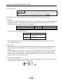
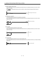
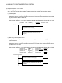
Configure an electromagnetic brake circuit so that it is activated also by an external emergency stop
switch.
Contacts must be opened by servo-on
(SON) OFF, trouble (ALM) and
electromagnetic brake interlock (MBR).
Contacts must be opened by an
emergency stop switch.
Servo motor
SON
B
RA
24VDC
U
Electromagnetic brake
When any alarm has occurred, eliminate its cause, ensure safety, and deactivate the alarm before
restarting operation.
When power is restored after an instantaneous power failure, keep away from the machine because the
machine may be restarted suddenly (design the machine so that it is secured against hazard if restarted).
(6) Maintenance, inspection and parts replacement
CAUTION
With age, the electrolytic capacitor of the converter unit and controller (drive unit) will deteriorate. To
prevent a secondary accident due to a fault, it is recommended to replace the electrolytic capacitor every
10 years when used in general environment. Please contact your local sales office.
(7) General instruction
To illustrate details, the equipment in the diagrams of this Specifications and Instruction Manual may have
been drawn without covers and safety guards. When the equipment is operated, the covers and safety
guards must be installed as specified. Operation must be performed in accordance with this Specifications
and Instruction Manual.
A- 8
DISPOSAL OF WASTE
Please dispose a converter unit, controller (drive unit), battery (primary battery) and other options according to
your local laws and regulations.
EEP-ROM life
The number of write times to the EEP-ROM, which stores parameter settings, etc., is limited to 100,000. If the
total number of the following operations exceeds 100,000, the converter unit, controller (drive unit) and/or
converter unit may fail when the EEP-ROM reaches the end of its useful life.
Write to the EEP-ROM due to parameter setting changes
Home position setting in the absolute position detection system
Write to the EEP-ROM due to device changes
Precautions for Choosing the Products
SMC will not be held liable for damage caused by factors found not to be the cause of SMC; machine
damage or lost profits caused by faults in the SMC products; damage, secondary damage, accident
compensation caused by special factors unpredictable by SMC; damages to products other than SMC
products; and to other duties.
COMPLIANCE WITH THE EUROPEAN EC
DIRECTIVES
Refer to Appendix 9 for the compliance with EC Directives.
COMPLIANCE WITH UL/C-UL STANDARD
Refer to Appendix 10 for the compliance with UL/C-UL standard.
<<About the manuals>>
This Instruction Manual and the LECSB□-□ Instruction Manual (Vol.2) are required if you use the
General-Purpose AC servo LECSB□-□ for the first time.
Relevant manuals
Manual name
Manual No.
LECSB□-□ Series Instructions and Cautions for Safe Use of AC Servos
IB(NA)0300077
(Enclosed in converter unit and controller (drive unit).)
LECSB□-□ Instruction Manual (Vol.2)
SH(NA)030041
EMC Installation Guidelines
IB(NA)67310
<<Wiring>>
Wires mentioned in this instruction manual are selected based on the ambient temperature of 40
A- 9
(104 ).
MEMO
A - 10
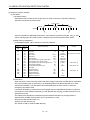
CONTENTS
1. FUNCTIONS AND CONFIGURATION
1 - 1 to 1 -13
1.1 Summary .................................................................................................................................................. 1 - 1
1.2 Function block diagram............................................................................................................................ 1 - 2
1.3 Servo amplifier standard specifications................................................................................................... 1 - 3
1.4 Function list .............................................................................................................................................. 1 - 4
1.4.1 Applicable control mode for each actuator....................................................................................... 1 - 7
1.5 Model code definition ............................................................................................................................... 1 - 8
1.6 Combination with servo motor ................................................................................................................. 1 - 9
1.7 Structure .................................................................................................................................................. 1 -10
1.7.1 Parts identification ............................................................................................................................ 1 -10
1.8 Configuration including auxiliary equipment .......................................................................................... 1 -11
2. INSTALLATION
2 - 1 to 2 - 6
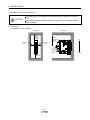
2.1 Installation direction and clearances ....................................................................................................... 2 - 2
2.2 Keep out foreign materials....................................................................................................................... 2 - 4
2.3 Cable stress ............................................................................................................................................. 2 - 5
2.4 Inspection items ....................................................................................................................................... 2 - 5
2.5 Parts having service lives ........................................................................................................................ 2 - 6
3. SIGNALS AND WIRING
3 - 1 to 3 -66
3.1 Input power supply circuit ........................................................................................................................ 3 - 2
3.2 I/O signal connection example ................................................................................................................ 3 - 5
3.2.1 Position control mode........................................................................................................................ 3 - 5
3.2.2 Speed control mode .......................................................................................................................... 3 - 7
3.2.3 Torque control mode ......................................................................................................................... 3 - 9
3.3 Explanation of power supply system ...................................................................................................... 3 -11
3.3.1 Signal explanations .......................................................................................................................... 3 -11
3.3.2 Power-on sequence ......................................................................................................................... 3 -12
3.3.3 CNP1, CNP2, CNP3 wiring method ................................................................................................ 3 -14
3.4 Connectors and signal arrangements .................................................................................................... 3 -20
3.5 Signal explanations ................................................................................................................................. 3 -24
3.6 Detailed description of the signals.......................................................................................................... 3 -37
3.6.1 Position control mode....................................................................................................................... 3 -37
3.6.2 Speed control mode ......................................................................................................................... 3 -41
3.6.3 Torque control mode ........................................................................................................................ 3 -43
3.6.4 Position/speed control change mode .............................................................................................. 3 -46
3.6.5 Speed/torque control change mode ................................................................................................ 3 -48
3.6.6 Torque/position control change mode ............................................................................................. 3 -50
3.7 Alarm occurrence timing chart................................................................................................................ 3 -51
3.8 Interfaces................................................................................................................................................. 3 -52
3.8.1 Internal connection diagram ............................................................................................................ 3 -52
3.8.2 Detailed description of interfaces..................................................................................................... 3 -53
1
3.8.3 Source I/O interfaces ....................................................................................................................... 3 -57
3.9 Treatment of cable shield external conductor ........................................................................................ 3 -58
3.10 Connection of servo amplifier and servo motor ................................................................................... 3 -59
3.10.1 Connection instructions.................................................................................................................. 3 -59
3.10.2 Power supply cable wiring diagrams ............................................................................................. 3 -60
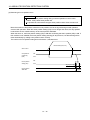
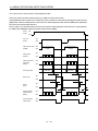
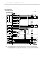
3.11 Servo motor with an electromagnetic brake......................................................................................... 3 -61
3.11.1 Safety precautions ......................................................................................................................... 3 -61
3.11.2 Setting............................................................................................................................................. 3 -61
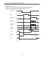
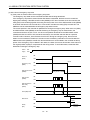
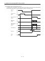
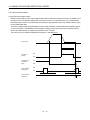
3.11.3 Timing charts.................................................................................................................................. 3 -62
3.11.4 Wiring diagrams (HF-MP series HF-KP series servo motor) ..................................................... 3 -64
3.12 Grounding.............................................................................................................................................. 3 -66
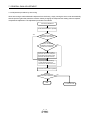
4. STARTUP
4 - 1 to 4 -18
4.1 Switching power on for the first time ....................................................................................................... 4 - 1
4.1.1 Startup procedure.............................................................................................................................. 4 - 1
4.1.2 Wiring check ...................................................................................................................................... 4 - 2
4.1.3 Surrounding environment.................................................................................................................. 4 - 3
4.2 Startup in position control mode .............................................................................................................. 4 - 4
4.2.1 Power on and off procedures............................................................................................................ 4 - 4
4.2.2 Stop.................................................................................................................................................... 4 - 4
4.2.3 Test operation.................................................................................................................................... 4 - 5
4.2.4 Parameter setting .............................................................................................................................. 4 - 6
4.2.5 Actual operation ................................................................................................................................ 4 - 7
4.2.6 Trouble at start-up ............................................................................................................................. 4 - 7
4.3 Startup in speed control mode................................................................................................................. 4 - 9
4.3.1 Power on and off procedures............................................................................................................ 4 - 9
4.3.2 Stop................................................................................................................................................... 4 -10
4.3.3 Test operation................................................................................................................................... 4 -11
4.3.4 Parameter setting ............................................................................................................................. 4 -12
4.3.5 Actual operation ............................................................................................................................... 4 -13
4.3.6 Trouble at start-up ............................................................................................................................ 4 -13
4.4 Startup in torque control mode ............................................................................................................... 4 -14
4.4.1 Power on and off procedures........................................................................................................... 4 -14
4.4.2 Stop................................................................................................................................................... 4 -15
4.4.3 Test operation .................................................................................................................................. 4 -16
4.4.4 Parameter setting ............................................................................................................................. 4 -17
4.4.5 Actual operation ............................................................................................................................... 4 -18
4.4.6 Trouble at start-up ............................................................................................................................ 4 -18
5. PARAMETERS
5 - 1 to 5 -59
5.1 Basic setting parameters (No.PA
).................................................................................................... 5 - 1
5.1.1 Parameter list .................................................................................................................................... 5 - 1
5.1.2 Parameter write inhibit ...................................................................................................................... 5 - 2
5.1.3 Selection of control mode ................................................................................................................. 5 - 3
5.1.4 Selection of regenerative option ....................................................................................................... 5 - 6
5.1.5 Using absolute position detection system ........................................................................................ 5 - 7
2
5.1.6 Using electromagnetic brake interlock (MBR).................................................................................. 5 - 7
5.1.7 Number of command input pulses per servo motor revolution........................................................ 5 - 8
5.1.8 Electronic gear................................................................................................................................... 5 - 9
5.1.9 Auto tuning ....................................................................................................................................... 5 -13
5.1.10 In-position range ............................................................................................................................ 5 -14
5.1.11 Torque limit..................................................................................................................................... 5 -15
5.1.12 Selection of command pulse input form ........................................................................................ 5 -16
5.1.13 Selection of servo motor rotation direction.................................................................................... 5 -17
5.1.14 Encoder output pulse ..................................................................................................................... 5 -17
5.2 Gain/filter parameters (No. PB
)....................................................................................................... 5 -19
5.2.1 Parameter list ................................................................................................................................... 5 -19
5.2.2 Detail list ........................................................................................................................................... 5 -21
5.2.3 Position smoothing.......................................................................................................................... 5 –32
5.3 Extension setting parameters (No. PC
) .......................................................................................... 5 -33
5.3.1 Parameter list ................................................................................................................................... 5 -33
5.3.2 List of details..................................................................................................................................... 5 -34
5.3.3 Analog monitor ................................................................................................................................. 5 -44
5.3.4 Alarm history clear............................................................................................................................ 5 -47
5.4 I/O setting parameters (No. PD
) ..................................................................................................... 5 -48
5.4.1 Parameter list ................................................................................................................................... 5 -48
5.4.2 List of details..................................................................................................................................... 5 -49
5.4.3 Using forward/reverse rotation stroke end to change the stopping pattern ................................... 5 -58
6. DISPLAY AND OPERATION SECTIONS
6 - 1 to 6 -22
6.1 Overview................................................................................................................................................... 6 - 1
6.2 Display sequence..................................................................................................................................... 6 - 2
6.3 Status display ........................................................................................................................................... 6 - 3
6.3.1 Display transition ............................................................................................................................... 6 - 3
6.3.2 Display examples .............................................................................................................................. 6 - 4
6.3.3 Status display list............................................................................................................................... 6 - 5
6.3.4 Changing the status display screen.................................................................................................. 6 - 6
6.4 Diagnostic mode ...................................................................................................................................... 6 - 7
6.5 Alarm mode .............................................................................................................................................. 6 - 8
6.6 Parameter mode ..................................................................................................................................... 6 -10
6.6.1 Parameter mode transition............................................................................................................... 6 -10
6.6.2 Operation example........................................................................................................................... 6 -11
6.7 External I/O signal display ...................................................................................................................... 6 -13
6.8 Output signal (DO) forced output............................................................................................................ 6 -16
6.9 Test operation mode ............................................................................................................................... 6 -17
6.9.1 Mode change.................................................................................................................................... 6 -17
6.9.2 JOG operation .................................................................................................................................. 6 -18
6.9.3 Positioning operation........................................................................................................................ 6 -19
6.9.4 Motor-less operation ........................................................................................................................ 6 -21
7. GENERAL GAIN ADJUSTMENT
7 - 1 to 7 -11
7.1 Different adjustment methods.................................................................................................................. 7 - 1
3
7.1.1 Adjustment on a single servo amplifier............................................................................................. 7 - 1
7.1.2 Adjustment using MR Configurator................................................................................................... 7 - 2
7.2 Auto tuning ............................................................................................................................................... 7 - 3
7.2.1 Auto tuning mode .............................................................................................................................. 7 - 3
7.2.2 Auto tuning mode basis .................................................................................................................... 7 - 4
7.2.3 Adjustment procedure by auto tuning............................................................................................... 7 - 5
7.2.4 Response level setting in auto tuning mode .................................................................................... 7 - 6
7.3 Manual mode 1 (simple manual adjustment).......................................................................................... 7 - 7
7.4 Interpolation mode .................................................................................................................................. 7 -10
8. SPECIAL ADJUSTMENT FUNCTIONS
8 - 1 to 8 -19
8.1 Function block diagram............................................................................................................................ 8 - 1
8.2 Adaptive filter ........................................................................................................................................ 8 - 1
8.3 Machine resonance suppression filter..................................................................................................... 8 - 4
8.4 Advanced vibration suppression control ................................................................................................. 8 - 7
8.5 Low-pass filter ......................................................................................................................................... 8 -11
8.6 Gain changing function ........................................................................................................................... 8 -11
8.6.1 Applications ...................................................................................................................................... 8 -11
8.6.2 Function block diagram.................................................................................................................... 8 -12
8.6.3 Parameters ....................................................................................................................................... 8 -13
8.6.4 Gain changing procedure................................................................................................................. 8 -15
8.7 Vibration suppression control filter 2 ...................................................................................................... 8 -17
9. TROUBLESHOOTING
9 - 1 to 9 -28
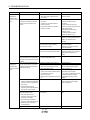
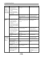
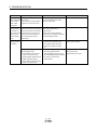
9.1 Alarms and warning list............................................................................................................................ 9 - 1
9.2 Remedies for alarms................................................................................................................................ 9 - 2
9.3 Remedies for warnings ........................................................................................................................... 9 -16
9.4 Troubles without an alarm/warning ........................................................................................................ 9 -18
10. OUTLINE DRAWINGS
10- 1 to 10- 5
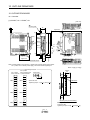
10.1 Controller ............................................................................................................................................. 10- 1
10.2 Connector.............................................................................................................................................. 10- 3
11. CHARACTERISTICS
11- 1 to 11 - 7
11.1 Overload protection characteristics ...................................................................................................... 11- 1
11.2 Power supply equipment capacity and generated loss ....................................................................... 11- 3
11.3 Dynamic brake characteristics.............................................................................................................. 11- 4
11.3.1 Dynamic brake operation............................................................................................................... 11- 4
11.3.2 The dynamic brake at the load inertia moment............................................................................. 11- 5
11.4 Cable flexing life.................................................................................................................................... 11- 6
11.5 Inrush currents at power-on of main circuit and control circuit............................................................ 11- 6
12. OPTIONS AND AUXILIARY EQUIPMENT
12- 1 to 12 -36
12.1 Cable/connector sets ............................................................................................................................ 12- 1
4
12.1.1 Combinations of cable/connector sets .......................................................................................... 12- 2
12.1.2 Encoder cable/connector sets ....................................................................................................... 12- 4
12.1.3 Motor cables................................................................................................................................... 12- 6
12.1.4 Lock cables .................................................................................................................................... 12- 8
12.2 Regenerative options ............................................................................................................................ 12- 9
12.3 Junction terminal block MR-TB50 ....................................................................................................... 12-12
12.4 MR Configurator................................................................................................................................... 12-13
12.5 Battery unit MR-J3BAT ........................................................................................................................ 12-16
12.6 Selection example of wires.................................................................................................................. 12-17
12.7 No-fuse breakers, fuses, magnetic contactors ................................................................................... 12-21
12.8 Noise reduction techniques ................................................................................................................. 12-22
12.9 Leakage current breaker...................................................................................................................... 12-30
12.10 EMC filter (recommended) ............................................................................................................... 12-32
13. COMMUNICATION FUNCTION
13- 1 to 13-34
13.1 Configuration ......................................................................................................................................... 13- 1
13.2 Communication specifications .............................................................................................................. 13- 3
13.2.1 Communication overview............................................................................................................... 13- 3
13.2.2 Parameter setting........................................................................................................................... 13- 4
13.3 Protocol ................................................................................................................................................. 13- 5
13.3.1 Transmission data configuration.................................................................................................... 13- 5
13.3.2 Character codes............................................................................................................................. 13- 6
13.3.3 Error codes ..................................................................................................................................... 13- 7
13.3.4 Checksum....................................................................................................................................... 13- 7
13.3.5 Time-out ......................................................................................................................................... 13- 8
13.3.6 Retry ............................................................................................................................................... 13- 8
13.3.7 Initialization..................................................................................................................................... 13- 9
13.3.8 Communication procedure example.............................................................................................. 13- 9
13.4 Command and data No. list ................................................................................................................. 13-10
13.4.1 Read commands ........................................................................................................................... 13-10
13.4.2 Write commands ........................................................................................................................... 13-14
13.5 Detailed explanations of commands ................................................................................................... 13-16
13.5.1 Data processing ............................................................................................................................ 13-16
13.5.2 Status display ................................................................................................................................ 13-18
13.5.3 Parameters .................................................................................................................................... 13-19
13.5.4 External I/O signal statuses (DIO diagnosis) ............................................................................... 13-22
13.5.5 Input device ON/OFF .................................................................................................................... 13-25
13.5.6 Disable/enable of I/O devices (DIO)............................................................................................. 13-25
13.5.7 Input devices ON/OFF (test operation) ........................................................................................ 13-26
13.5.8 Test operation mode ..................................................................................................................... 13-27
13.5.9 Output signal pin ON/OFF output signal (DO) forced output....................................................... 13-30
13.5.10 Alarm history ............................................................................................................................... 13-31
13.5.11 Current alarm .............................................................................................................................. 13-32
13.5.12 Other commands......................................................................................................................... 13-33
14. ABSOLUTE POSITION DETECTION SYSTEM
14- 1 to 14-65
5
14.1 Outline ................................................................................................................................................... 14- 1
14.1.1 Features ......................................................................................................................................... 14- 1
14.1.2 Restrictions..................................................................................................................................... 14- 2
14.2 Specifications ........................................................................................................................................ 14- 3
14.3 Battery replacement procedure ............................................................................................................ 14- 4
14.3.1 When replacing battery with the control circuit power ON............................................................ 14- 4
14.4 Battery installation procedure ............................................................................................................... 14- 5
14.5 Standard connection diagram............................................................................................................... 14- 6
14.6 Signal explanation................................................................................................................................. 14- 7
14.8 Startup procedure ................................................................................................................................. 14- 8
14.8 Absolute position data transfer protocol............................................................................................... 14- 9
14.8.1 Data transfer procedure ................................................................................................................. 14- 9
14.8.2 Transfer method ............................................................................................................................ 14-10
14.8.3 Home position setting.................................................................................................................... 14-21
14.8.4 Use of servo motor with an electromagnetic brake...................................................................... 14-23
14.8.5 How to process the absolute position data at detection of stroke end........................................14-24
14.9 Examples of use................................................................................................................................... 14-25
14.9.1 MELSEC FX(2N)-32MT (FX(2N)-1PG)........................................................................................... 14-25
14.9.2 MELSEC A1SD75......................................................................................................................... 14-37
14.9.3 MELSEC QD75 ............................................................................................................................. 14-50
14.10 Absolute position data transfer errors ............................................................................................... 14-58
14.10.1 Corrective actions ....................................................................................................................... 14-58
14.10.2 Error resetting conditions ............................................................................................................ 14-60
14.11 Communication-based ABS transfer system .................................................................................... 14-61
14.11.1 Serial communication command ................................................................................................ 14-61
14.11.2 Absolute position data transfer protocol..................................................................................... 14-61
14.12 Confirmation of absolute position detection data.............................................................................. 14-65
APPENDIX
App.- 1 to App.-16
App. 1 Parameter list..................................................................................................................................App.- 1
App. 2 Signal layout recording paper ........................................................................................................App.- 3
App. 3 Status display block diagram .........................................................................................................App.- 4
App. 4 Handling of AC servo amplifier batteries for the United Nations
Recommendations on the Transport of Dangerous Goods..........................................................App.- 5
App. 5 Symbol for the new EU Battery Directive ......................................................................................App.- 6
App. 6 Compliance with the European EC directives ...............................................................................App.- 7
App. 7 Conformance with UL/C-UL standard.......................................................................................... App.-10
6
1. FUNCTIONS AND CONFIGURATION
UU1. FUNCTIONS AND CONFIGURATION
1.1 Summary
It has position control, speed control and torque control modes. Further, it can perform operation with the
control modes changed, e.g. position/speed control, speed/torque control and torque/position control. Hence, it
is applicable to a wide range of fields, not only precision positioning and smooth speed control of machine tools
and general industrial machines but also line control and tension control.
As this new series has the USB or RS-422 serial communication function, a MR Configurator installed personal
computer or the like can be used to perform parameter setting, test operation, status display monitoring, gain
adjustment, etc.
With real-time auto tuning, you can automatically adjust the servo gains according to the machine.
The LECSB□-□ series servo motor with an absolute position encoder which has the resolution of 262144
pulses/rev to ensure. Simply adding a battery to the controller makes up an absolute position detection system.
This makes home position return unnecessary at power-on or alarm occurrence by setting a home position
once.
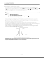
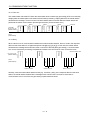
(1) Position control mode
An up to 1Mpps high-speed pulse train is used to control the speed and direction of a motor and execute
precision positioning of 262144 pulses/rev resolution.
The position smoothing function provides a choice of two different modes appropriate for a machine, so a
smoother start/stop can be made in response to a sudden position command.
A torque limit is imposed on the controller by the clamp circuit to protect the power transistor in the main
circuit from overcurrent due to sudden acceleration/deceleration or overload. This torque limit value can be
changed to any value with an external analog input or the parameter.
(2) Speed control mode
An external analog speed command (0 to 10VDC) or parameter-driven internal speed command (max. 7
speeds) is used to control the speed and direction of a servo motor smoothly.
There are also the acceleration/deceleration time constant setting in response to speed command, the
servo lock function at a stop time, and automatic offset adjustment function in response to external analog
speed command.
(3) Torque control mode
An external analog torque command (0 to 8VDC) is used to control the torque output by the servo motor.
To prevent unexpected operation under no load, the speed limit function (external or internal setting) is also
available for application to tension control, etc.
1- 1
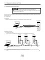
1. FUNCTIONS AND CONFIGURATION
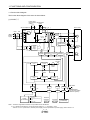
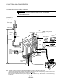
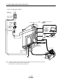
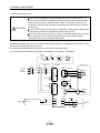
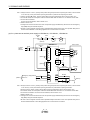
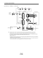
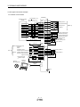
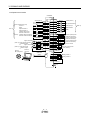
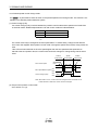
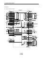
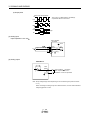
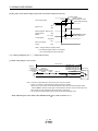
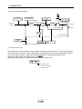
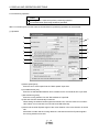
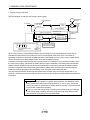
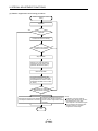
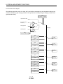
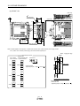
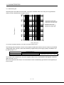
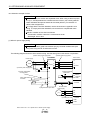
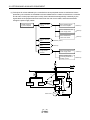
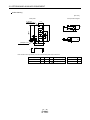
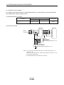
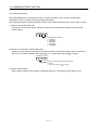
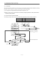
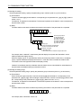
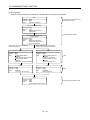
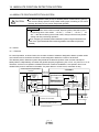
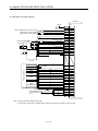
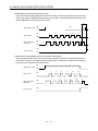
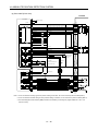
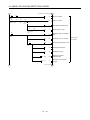
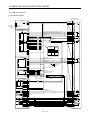
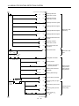
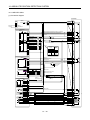
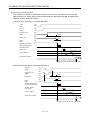
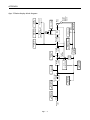
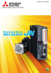
1.2 Function block diagram
The function block diagram of this servo is shown below.
(1) LECSB□-□
Power factor
improving DC Regenerative
option
reactor
Servo amplifier P1
NFB
(Note 2)
Power
supply
MC
L1
P2
P(
)C
Diode
stack Relay
D
N(
Servo motor
)
(Note 1)
L2
Current
detector
L3
Regenerative TR
U
U
V
V
W
W
M
CHARGE
lamp
(Note 3) Cooling fan
Dynamic
brake circuit
RA
Control
circuit
power
supply
L21
24VDC
Base
amplifier
Voltage
detection
Current
detection
Overcurrent
protection
B1
ElectroB magnetic
brake
B2
CN2
L11
Encoder
Virtual
encoder
Pulse input
Model position
control
Model speed
control
Virtual
motor
Actual position
control
Model
speed
Model torque
Actual speed
control
A/D
Current
control
USB
RS-422
D/A
CN5
CN3
CN6
I/F
CN1
MR-J3BAT
CN4
Model
position
Optional battery
(for absolute position
detection system)
D I/O control
Analog
(2 channels)
Servo on
Command pulse train input
Start
Failure, etc.
Personal
computer
USB
Controller
RS-422
Analog monitor
(2 channels)
Note 1. The built-in regenerative resistor is not provided for the LECSB1-S5.
2. For 1-phase 200 to 230VAC, connect the power supply to L1, L2 and leave L3 open.
There is no L3 for 1-phase 100 to 120VAC power supply. For the specification of power supply, refer to section 1.3.
1- 2
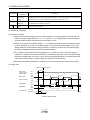
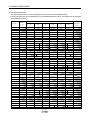
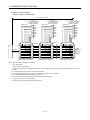
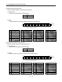
1. FUNCTIONS AND CONFIGURATION
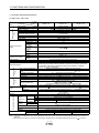
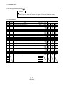
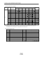
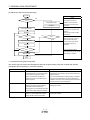
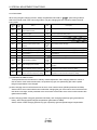
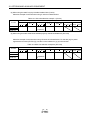
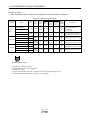
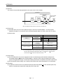
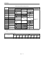
1.3 Controller standard specifications
(1) 200V class, 100V class
Controller
LECSB□-□
LECSB□-S5
LECSB□-S7
LECSB-□-S8
Main circuit power
supply
Output
Item
Rated voltage
Rated current
Voltage, frequency
Rated current
[A]
1.1
[A]
0.9
Permissible voltage fluctuation
Permissible frequency fluctuation
Power supply capacity
Inrush current
Voltage, frequency
Rated current
[A]
Permissible voltage
fluctuation
Control circuit power
Permissible
supply
frequency
fluctuation
Power
consumption
[W]
Inrush current
Voltage
Interface power supply
Power supply
capacity
Control System
Dynamic brake
Protective functions
Speed control Position control
mode
mode
Max. input pulse frequency
Command pulse multiplying
factor
In-position range setting
Error excessive
Torque limit
Speed control range
Analog speed command input
Speed fluctuation ratio
Torque control
mode
Torque limit
Analog torque command
input
Speed limit
Compliance to standards
Environmental conditions
Structure
Mass
3-phase 170VAC
1.5
3-phase or 1-phase 200 to 230VAC, 50/60Hz
1.5
3-phase or 1-phase
170 to 253VAC
Within 5
Refer to section 11.2
Refer to section 11.5
1-phase 200 to 230VAC, 50/60Hz
0.2
Ambient
temperature
Ambient
humidity
In operation
In storage
[ ]
[ ]
[ ]
[ ]
2.8
2.6
1-phase 170 to 253VAC
Within
5
30
Refer to section 11.5
24VDC 10
(Note 1) 0.3A
Sine-wave PWM control, current control system
Built-in
Overcurrent shut-off, regenerative overvoltage shut-off, overload shut-off (electronic
thermal relay), servo motor overheat protection, encoder error protection, regenerative
error protection, undervoltage, instantaneous power failure protection, overspeed
protection, excessive error protection
1Mpps (for differential receiver), 200kpps (for open collector)
Electronic gear A:1 to 1048576, B:1 to 1048576, 1/10
A/B
2000
0 to
10000 pulse (command pulse unit)
3 revolutions
Set by parameter setting or external analog input (0 to 10VDC/maximum torque)
Analog speed command 1: 2000, internal speed command 1: 5000
0 to 10VDC / Rated speed
0.01 or less (load fluctuation 0 to 100 )
0 (power fluctuation 10 )
0.2 or less (ambient temperature 25 10 (59 to 95 ))
Set by parameter setting or external analog input (0 to 10VDC/maximum torque)
0 to
8VDC / Maximum torque (input impedance 10 to 12k )
Set by parameter setting or external analog input (0 to 10VDC/Rated speed)
CE (LVD: IEC/EN 50178, EMC: IEC/EN 61800-3)
UL (UL 508C)
Natural-cooling, open
(Note 2) 0 to 55 (non-freezing)
(Note 2) 32 to 131 (non-freezing)
20 to 65 (non-freezing)
4 to 149 (non-freezing)
In operation
In storage
90 RH or less (non-condensing)
Ambient
Altitude
Vibration
[kg]
[lb]
Indoors (no direct sunlight),
Free from corrosive gas, flammable gas, oil mist, dust and dirt
Max. 1000m above sea level
2
5.9m/s or less at 10 to 55Hz (directions of X, Y and Z axes)
0.8
0.8
1.0
1.76
1.76
2.21
Note 1. 0.3A is the value applicable when all I/O signals are used. The current capacity can be decreased by reducing the number of
I/O points.
2. When closely mounting the controller of 3.5kW or less, operate them at the ambient temperatures of 0 to 45 or at 75% or
1- 3
1. FUNCTIONS AND CONFIGURATION
smaller effective load ratio.
3. When a UL/C-UL-compliant servo motor is used in combination, the value is 2.9A.
4. Use an external dynamic brake for this controller. Failure to do so will cause an accident because the servo motor does not stop
immediately but coasts at an emergency stop and such conditions. Ensure the safety in the entire system.
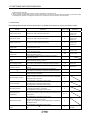
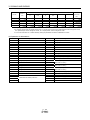
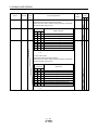
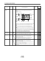
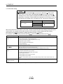
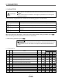
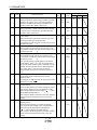
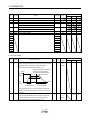
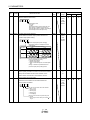
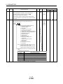
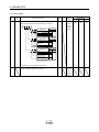
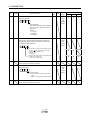
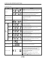
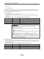
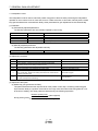
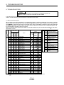
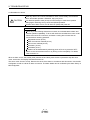
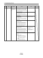
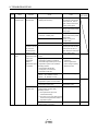
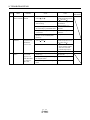
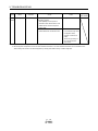
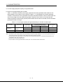
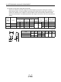
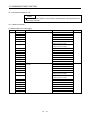
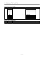
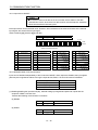
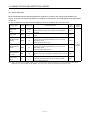
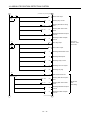
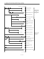
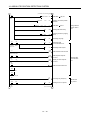
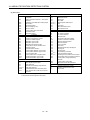
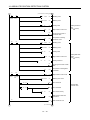
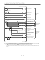
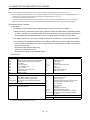
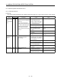
1.4 Function list
The following table lists the functions of this servo. For details of the functions, refer to the reference field.
Function
Description
(Note)
Control mode
Position control mode
This servo is used as position control servo.
P
Speed control mode
This servo is used as speed control servo.
S
Torque control mode
This servo is used as torque control servo.
T
Position/speed control
change mode
Speed/torque control change
mode
Torque/position control
change mode
Using input device, control can be switched between position
control and speed control.
Using input device, control can be switched between speed
control and torque control.
Using input device, control can be switched between torque
control and position control.
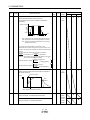
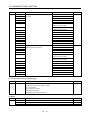
High-resolution encoder of 262144 pulses/rev is used as a
servo motor encoder.
Merely setting a home position once makes home position
return unnecessary at every power-on.
You can switch between gains during rotation and gains during
stop or use an input device to change gains during operation.
This function suppresses vibration at the arm end or residual
vibration.
Controller detects mechanical resonance and sets filter
characteristics automatically to suppress mechanical vibration.
Suppresses high-frequency resonance which occurs as servo
system response is increased.
Analyzes the frequency characteristic of the mechanical
system by simply connecting a personal computer installed MR
Configurator with a controller.
MR Configurator is necessary for this function.
Can simulate machine motions on a personal computer screen
on the basis of the machine analyzer results.
MR Configurator is necessary for this function.
Personal computer changes gains automatically and searches
for overshoot-free gains in a short time.
MR Configurator is necessary for this function.
This function provides better disturbance response in case of
low response level due to high load inertia moment ratio for the
roll send axes.
MR Configurator is necessary for this function.
Advanced Gain search automatically searches for the optimum
parameter for settle time to be short.
The gain can be adjusted by setting sequentially in accordance
with wizard screens.
MR Configurator is necessary for this function.
Suppresses vibration of 1 pulse produced at a servo motor
stop.
High-resolution encoder
Absolute position detection
system
Gain changing function
Advanced vibration
suppression control
Adaptive filter
Low-pass filter
Machine analyzer function
Machine simulation
Gain search function
Robust disturbance
compensation
Advanced Gain search
Slight vibration suppression
control
1- 4
Reference
Section 3.2.1
Section 3.6.1
Section 4.2
Section 3.2.2
Section 3.6.2
Section 4.3
Section 3.2.3
Section 3.6.3
Section 4.4
P/S
Section 3.6.4
S/T
Section 3.6.5
T/P
Section 3.6.6
P, S, T
P
Chapter 14
P, S
Section 8.6
P
Section 8.4
P, S, T
Section 8.2
P, S, T
Section 8.5
P
P
P
P, S, T
P
P
Parameters
No.PB24
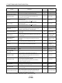
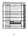
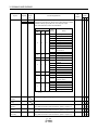
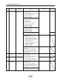
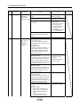
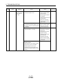
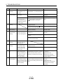
1. FUNCTIONS AND CONFIGURATION
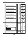
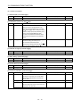
Electronic gear
Input pulses can be multiplied by 1/50 to 50.
Auto tuning
Automatically adjusts the gain to optimum value if load applied
to the servo motor shaft varies.
1- 5
P
P, S
Parameters
No.PA06, PA07
Chapter 7
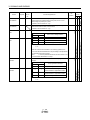
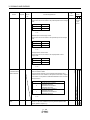
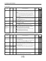
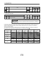
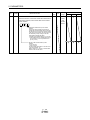
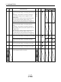
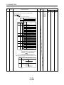
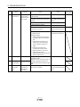
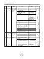
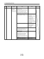
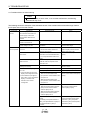
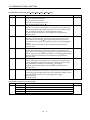
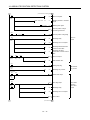
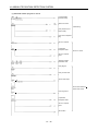
1. FUNCTIONS AND CONFIGURATION
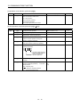
Function
Position smoothing
S-pattern acceleration/
deceleration time constant
Description
Speed can be increased smoothly in response to input pulse.
Speed can be increased and decreased smoothly.
(Note)
Control mode
Reference
P
Parameter No.PB03
S, T
Parameter No.PC03
Used when the built-in regenerative resistor of the controller
Regenerative option
does not have sufficient regenerative capability for the
P, S, T
Section 12.2
P, S, T
Section 12.3
P, S, T
Section 12.4
P, S, T
Parameter No.PC18
S
Parameter No.PC22
P
Section 5.1.12
regenerative power generated.
Used when the regenerative option cannot provide enough
Brake unit
regenerative power.
Can be used with the MR-J3-500A
MR-J3-700A.
Used when the regenerative option cannot provide enough
Return converter
regenerative power.
Can be used with the MR-J3-500A
Alarm history clear
Restart after instantaneous
power failure
Command pulse selection
Input signal selection
(Device settings)
Output signal selection
(Device settings)
MR-J3-700A.
Alarm history is cleared.
If the input power supply voltage had reduced to cause an
alarm but has returned to normal, the servo motor can be
restarted by merely switching on the start signal.
Command pulse train form can be selected from among three
different types.
Forward rotation start, reverse rotation start, servo-on (SON)
and other input device can be assigned to certain pins of the
Parameters
P, S, T
CN1 connectors.
No.PD03 to PD08,
PD10 to PD12
Trouble (ALM), dynamic brake interlock (MBR) and other
output device can be assigned to certain pins of the CN1
Parameters
P, S, T
connectors.
No.PD13 to PD16,
PD18
Section 3.6.1 (5)
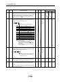
Torque limit
Servo motor torque can be limited to any value.
P, S
Speed limit
Servo motor speed can be limited to any value.
T
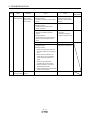
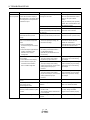
Parameter
Status display
Servo status is shown on the 5-digit, 7-segment LED display
P, S, T
Section 6.3
P, S, T
Section 6.7
P, S, T
Section 6.8
S, T
Section 6.4
P, S, T
Section 6.9
P, S, T
Parameter No.PC14
P, S, T
Section 12.8
P, S, T
Section 9.1
P, S, T
Section 12.8 (2)(C)
Section 5.1.11
Section 3.6.3 (3)
No.PC05 to PC11
External I/O signal display
Output signal (DO)
forced output
ON/OFF statuses of external I/O signals are shown on the
display.
Output signal can be forced on/off independently of the servo
status.
Use this function for output signal wiring check, etc.
Voltage is automatically offset to stop the servo motor if it does
Automatic VC offset
not come to a stop at the analog speed command (VC) or
analog speed limit (VLA) of 0V.
JOG operation, positioning operation, motor-less operation,
Test operation mode
DO forced output and program operation.
However, MR Configurator is necessary for positioning
operation and program operation.
Analog monitor output
MR Configurator
Alarm code output
Servo status is output in terms of voltage in real time.
Using a personal computer, parameter setting, test operation,
status display, etc. can be performed.
If an alarm has occurred, the corresponding alarm number is
output in 3-bit code.
The DI/DO signals, analog monitor input I/F, analog monitor
Controller diagnosis function
output, command pulse I/F and encoder pulse output are
checked. The diagnosis cable (MR-J3ACHECK) and MR
Configurator are necessary for this function.
Note. P: Position control mode, S: Speed control mode, T: Torque control mode
1- 6
1. FUNCTIONS AND CONFIGURATION
P/S: Position/speed control change mode, S/T: Speed/torque control change mode, T/P: Torque/position control change mode
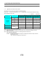
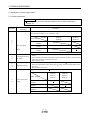
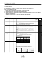
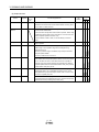
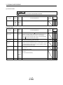
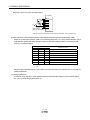
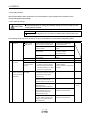
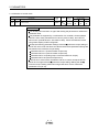
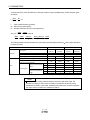
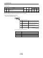
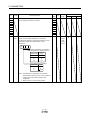
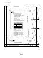
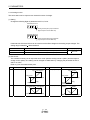
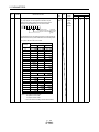
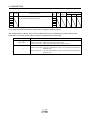
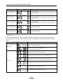
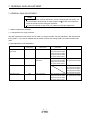
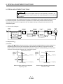
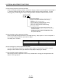
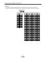
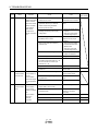
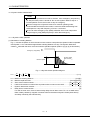
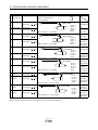
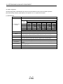
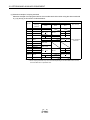
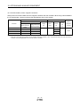
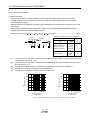
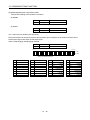
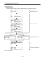
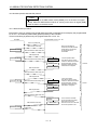
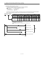
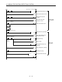
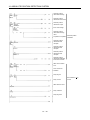
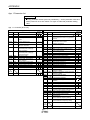
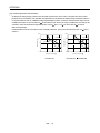
1.4.1
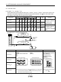
Applicable control mode for each actuator.
The following control mode can be selected for applicable actuators.
Please refer 「3. SIGNALS AND WIRING」and「5. PARAMETERS」about wiring and parameter setting.
Table. Applicable control mode.
(○:Applicable,×:Inapplicable)
Control mode
Controller type
Note 1)
(Selected by parameter number PA1.)
Actuator type
Position control
Speed control
Torque control
LEY
○
○Note 2)
○Note 3)
LJ1
○
×
×
LG1
○
×
×
LTF
○
×
×
LEF
○
×
×
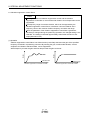
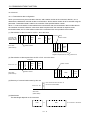
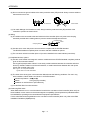
Command method
[Pulse train]
[ON/OFF Signal]
[ON/OFF Signal]
Operation method
Positioning operation
Setting speed operation
Setting torque operation
LECSB
(Absolute)
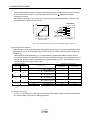
Note 1. The control change mode cannot be used.
Note 2. Make the moving range limitation by external sensor etc to avoid actuator hitting to the work
piece or stroke end.
Note 3. When using the pushing operation, the following parameter should be set.
If not, it will cause malfunction.
LECSB : The value of the parameter value [PC13] “Analog torque maximum output command”
should be 30% or less.
(30% = Maximum pushing force of the product.)
1- 7
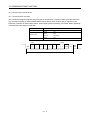
1. FUNCTIONS AND CONFIGURATION
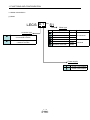
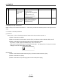
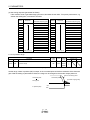
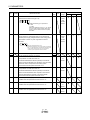
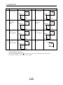
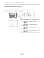
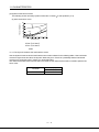
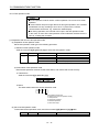
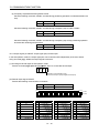
1.5 Model code definition
(1) Model
LECS A 1 - S1
Motor type
Type
Controller Type
A
B
Capacity
S1
AC Servo motor(S1,S2) 50,100W
Pulse input type
(Incremental encoder)
S3
S4
AC Servo motor(S3)
AC Servo motor(S4)
Pulse input type
(Absolute encoder)
S5
AC Servo motor(S5,S6) 50,100W
S7
AC Servo motor(S7)
S8
AC Servo motor(S8)
200W
Encoder
Incremental
400W
100W
200W
Absolute
Power supply
1- 8
1
AC100~120V 50,60Hz
2
AC200~230V 50,60Hz
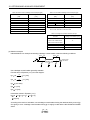
1. FUNCTIONS AND CONFIGURATION
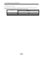
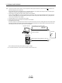
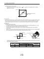
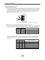
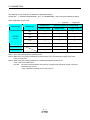
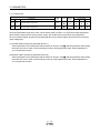
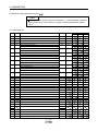
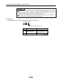
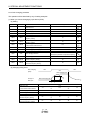
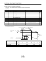
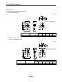
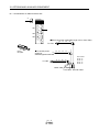
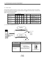
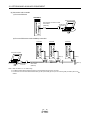
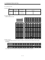
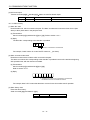
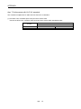
1.6 Combination with servo motor
The following table lists combinations of controller and servo motors. The same combinations apply to the
models with an electromagnetic brake and the models with a reduction gear.
Servo motors
Controller
LE-□-□
LECSB1-S5
053 13
LECSB1-S7
23
LECSB1-S8
43
1- 9
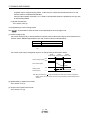
1. FUNCTIONS AND CONFIGURATION
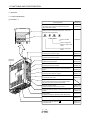
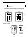
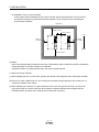
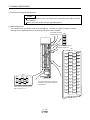
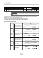
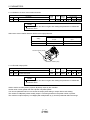
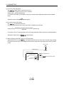
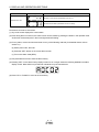
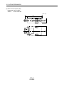
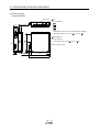
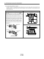
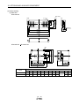
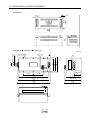
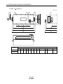
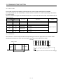
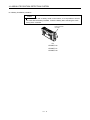
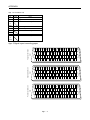
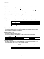
1.7 Structure
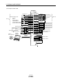
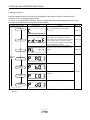
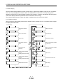
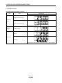
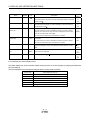
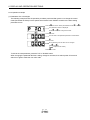
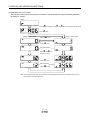
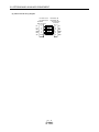
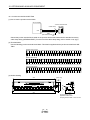
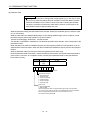
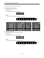
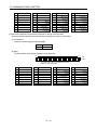
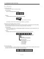
1.7.1 Parts identification
(1) LECSB□-□
Name/Application
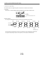
Display
The 5-digit, seven-segment LED shows the servo
status and alarm number.
Detailed
explanation
Chapter 6
Operation section
Used to perform status display, diagnostic, alarm and
parameter setting operations.
MODE
MODE
UP
DOWN
UP
DOWN
SET
Used to set data.
SET
Chapter 6
Used to change the
display or data in each
mode.
Used to change the
mode.
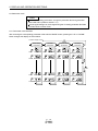
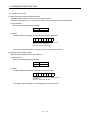
Main circuit power supply connector (CNP1)
Connect the input power supply.
Fixed part
(2 places)
Section 3.1
Section 3.3
USB communication connector (CN5)
Connect the personal computer.
Section 12.8
Analog monitor connector (CN6)
Outputs the analog monitor.
Section 3.2
Section 3.4
RS-422 communication connector (CN3)
Connect the personal computer.
Section 12.8
Chapter 13
Control circuit connector (CNP2)
Connect the control circuit power supply/regenerative
option.
Section 3.1
Section 3.3
I/O signal connector (CN1)
Used to connect digital I/O signals.
Section 3.2
Section 3.4
Servo motor power connector (CNP3)
Connect the servo motor.
Section 3.1
Section 3.3
Charge lamp
Lit to indicate that the main circuit is charged. While
this lamp is lit, do not reconnect the cables.
Encoder connector (CN2)
Used to connect the servo motor encoder.
Section 3.4
Section 12.1
Battery connector (CN4)
Used to connect the battery for absolute position data
backup.
Section 12.9
Chapter 14
Battery holder
Contains the battery for absolute position data backup.
Section 14.3
Rating plate
Section 1.5
Protective earth (PE) terminal (
Ground terminal.
1 - 10
)
Section 3.1
Section 3.3
1. FUNCTIONS AND CONFIGURATION
1.8 Configuration including auxiliary equipment
POINT
Equipment other than the controller and servo motor are optional or
recommended products.
(1) LECSB□-□
(a) For 3-phase or 1-phase 200 to 230VAC
RST
(Note 3)
Power supply
No-fuse breaker
(NFB) or fuse
CN6
Magnetic
contactor
(MC)
Servo amplifier
Personal
computer
(Note 2)
CN5
Line noise filter
(FR-BSF01)
MR Configurator
CN3
CN1
L1
L2
L3
(Note 2)
Power factor
improving DC
reactor
(FR-BEL)
Analog monitor
UV
W
P1
Junction terminal block
CN2
CN4
P2
(Note 1)
Battery
MR-J3BAT
Servo motor
P
C
Regenerative
option
L11
L21
Note 1. The battery (option) is used for the absolute position detection system in the position control mode.
2. The power factor improving AC reactor can also be used. In this case, the power factor improving DC reactor cannot be used.
When not using the power factor improving DC reactor, short P1 and P2.
3.For 1-phase 200 to 230VAC, connect the power supply to L1 L2 and leave L3 open. Refer to section 1.3 for the power supply
specification.
1 - 11
1. FUNCTIONS AND CONFIGURATION
(b) For 1-phase 100 to 120VAC
R
S
(Note 3)
Power supply
No-fuse breaker
(NFB) or fuse
CN6
Magnetic
contactor
(MC)
Analog monitor
Servo amplifier
Personal
computer
Power factor
improving AC
reactor
(FR-BAL)
CN5
Line noise filter
(FR-BSF01)
(Note 2)
MR Configurator
CN3
CN1
L1
L2
UV
W
Junction terminal block
CN2
CN4
(Note 1)
Battery
MR-J3BAT
Servo motor
P
C
Regenerative
option
L11
L21
Note 1. The battery (option) is used for the absolute position detection system in the position control mode.
2. The power factor improving DC reactor cannot be used.
3. Refer to section 1.3 for the power supply specification.
1 - 12
1. FUNCTIONS AND CONFIGURATION
MEMO
1 - 13
2. INSTALLATION
2. INSTALLATION
WARNING
To prevent electric shock, ground each equipment securely.
CAUTION
Stacking in excess of the limited number of product packages is not allowed.
Install the equipment to incombustibles. Installing them directly or close to
combustibles will led to a fire.
Install the equipment in a load-bearing place in accordance with this Instruction
Manual.
Do not get on or put heavy load on the equipment to prevent injury.
Use the equipment within the specified environmental condition range. (For details
of the environmental condition, refer to section 1.3.)
Provide an adequate protection to prevent screws, metallic detritus and other
conductive matter or oil and other combustible matter from entering the converter
unit and controller (drive unit).
Do not block the intake and exhaust areas of the converter unit, controller (drive
unit) and servo motor which has a cooling fan. Doing so may cause faults.
Do not subject the converter unit and controller (drive unit) to drop impact or shock
loads as they are precision equipment.
Do not install or operate a faulty converter unit and controller (drive unit).
When the product has been stored for an extended period of time, contact your local
sales office.
When handling the converter unit and controller (drive unit), be careful about the
edged parts such as the corners of the each unit.
The converter unit and controller (drive unit) must be installed in the metal cabinet
(control box).
2- 1
2. INSTALLATION
2.1 Installation direction and clearances
CAUTION
The equipment must be installed in the specified direction. Otherwise, a fault may
occur.
Leave specified clearances between the controller and control box inside walls or
other equipment.
(1) 7kW or less
(a) Installation of one controller
Control box
Control box
40mm
or more
Servo
amplifier
10mm or
more
Wiring
allowance
80mm
Top
10mm or
more
Bottom
40mm
or more
2- 2
2. INSTALLATION
(b) Installation of two or more controllers
POINT
Close mounting is available for the controller of under 3.5kW for 200V class and
400W for 100V class.
Leave a large clearance between the top of the controller and the internal surface of the control box,
and install a cooling fan to prevent the internal temperature of the control box from exceeding the
environmental conditions.
When installing the controllers closely, leave a clearance of 1mm between the adjacent controllers in
consideration of mounting tolerances.
In this case, make circumference temperature into 0 to 45 , or use it at 75 or a smaller effective load ratio.
Control box
Control box
100mm or more
10mm
or more
100mm or more
1mm
1mm
Top
30mm
or more
30mm
or more
30mm
or more
30mm
or more
Bottom
40mm or more
40mm or more
Mounting closely
Leaving clearance
(2) 11k to 22kW or more
(a) Installation of one controller
Control box
Control box
40mm or more
Wiring
allowance
80mm
Servo amplifier
Top
10mm
or more
10mm
or more
Bottom
120mm
or more
2- 3
2. INSTALLATION
(b) Installation of two or more controllers
Leave a large clearance between the top of the controller and the internal surface of the control box,
and install a cooling fan to prevent the internal temperature of the control box from exceeding the
environmental conditions.
Control box
100mm or more
10mm or more
Top
30mm
or more
30mm
or more
Bottom
120mm or more
(3) Others
When using heat generating equipment such as the regenerative option, install them with full consideration
of heat generation so that the controller is not affected.
Install the controller on a perpendicular wall in the correct vertical direction.
2.2 Keep out foreign materials
(1) When installing the unit in a control box, prevent drill chips and wire fragments from entering the controller.
(2) Prevent oil, water, metallic dust, etc. from entering the controller through openings in the control box or a
cooling fan installed on the ceiling.
(3) When installing the control box in a place where there are much toxic gas, dirt and dust, conduct an air
purge (force clean air into the control box from outside to make the internal pressure higher than the
external pressure) to prevent such materials from entering the control box.
2- 4
2. INSTALLATION
2.3 Cable stress
(1) The way of clamping the cable must be fully examined so that flexing stress and cable's own weight stress
are not applied to the cable connection.
(2) For use in any application where the servo motor moves, fix the cables (encoder, power supply, brake) with
having some slack from the connector connection part of the servo motor to avoid putting stress on the
connector connection part. Use the optional encoder cable within the flexing life range. Use the power
supply and brake wiring cables within the flexing life of the cables.
(3) Avoid any probability that the cable sheath might be cut by sharp chips, rubbed by a machine corner or
stamped by workers or vehicles.
(4) For installation on a machine where the servo motor will move, the flexing radius should be made as large
as possible. Refer to section 11.4 for the flexing life.
2.4 Inspection items
WARNING
Before starting maintenance and/or inspection, turn off the power and wait for 15
minutes or longer until the charge lamp turns off. Then, confirm that the voltage
between P( ) and N( ) is safe with a voltage tester and others. Otherwise, an
electric shock may occur. In addition, always confirm from the front of the controller
whether the charge lamp is off or not.
Any person who is involved in inspection should be fully competent to do the work.
Otherwise, you may get an electric shock. For repair and parts replacement, contact
your local sales office.
POINT
Do not test the controller with a megger (measure insulation resistance), or it
may become faulty.
Do not disassemble and/or repair the equipment on customer side.
It is recommended to make the following checks periodically.
(1) Check for loose terminal block screws. Retighten any loose screws.
(2) Check the cables and the wires for scratches and cracks. Perform periodic inspection according to
operating conditions.
2- 5
2. INSTALLATION
2.5 Parts having service lives
The following parts must be changed periodically as listed below. If any part is found faulty, it must be changed
immediately even when it has not yet reached the end of its life, which depends on the operating method and
environmental conditions. For parts replacement, please contact your local sales office.
Part name
Smoothing capacitor
Controller
Life guideline
10 years
Number of power-on and number of emergency
Relay
stop times : 100,000 times
Cooling fan
Absolute position battery
10,000 to 30,000hours (2 to 3 years)
Refer to section 14.2
(1) Smoothing capacitor
Affected by ripple currents, etc. and deteriorates in characteristic. The life of the capacitor greatly depends
on ambient temperature and operating conditions. The capacitor will reach the end of its life in 10 years of
continuous operation in normal air-conditioned environment (40 (104 ) surrounding air temperature or
less).
(2) Relays
Their contacts will wear due to switching currents and contact faults occur. Relays reach the end of their life
when the cumulative number of power-on and emergency stop times is 100,000, which depends on the
power supply capacity.
(3) Controller cooling fan
The cooling fan bearings reach the end of their life in 10,000 to 30,000 hours. Normally, therefore, the
cooling fan must be changed in a few years of continuous operation as a guideline.
It must also be changed if unusual noise or vibration is found during inspection.
2- 6
3. SIGNALS AND WIRING
3. SIGNALS AND WIRING
WARNING
Any person who is involved in wiring should be fully competent to do the work.
Before wiring, turn off the power and wait for 15 minutes or longer until the charge
lamp turns off. Then, confirm that the voltage between P( ) and N( ) is safe with a
voltage tester and others. Otherwise, an electric shock may occur. In addition,
always confirm from the front of the controller whether the charge lamp is off or not.
Ground the controller and the servo motor securely.
Do not attempt to wire the controller and servo motor until they have been installed.
Otherwise, you may get an electric shock.
The cables should not be damaged, stressed excessively, loaded heavily, or
pinched. Otherwise, you may get an electric shock.
Wire the equipment correctly and securely. Otherwise, the servo motor may operate
unexpected resulting in injury.
Connect cables to correct terminals to prevent a burst, fault, etc.
Ensure that polarity ( , ) is correct. Otherwise, a burst, damage, etc. may occur.
The surge absorbing diode installed to the DC relay for control output should be
fitted in the specified direction. Otherwise, the emergency stop and other protective
circuits may not operate.
Controller
Servo
amplifier
Controller
Servo
amplifier
24VDC
DOCOM
CAUTION
Control output
signal
DICOM
RA
For sink output interface
24VDC
DOCOM
Control output
signal
DICOM
RA
For source output interface
Use a noise filter, etc. to minimize the influence of electromagnetic interference,
which may be given to electronic equipment used near the controller.
Do not install a power capacitor, surge killer or radio noise filter (FR-BIF-(H) option)
with the power line of the servo motor.
When using the regenerative resistor, switch power off with the alarm signal.
Otherwise, a transistor fault or the like may overheat the regenerative resistor,
causing a fire.
Do not modify the equipment.
During power-on, do not open or close the motor power line. Otherwise, a
malfunction or faulty may occur.
3- 1
3. SIGNALS AND WIRING
3.1 Input power supply circuit
CAUTION
Always connect a magnetic contactor between the main circuit power and L1, L2,
and L3 of the controller, and configure the wiring to be able to shut down the power
supply on the side of the controller’s power supply. If a magnetic contactor is not
connected, continuous flow of a large current may cause a fire when the controller
malfunctions.
Use the trouble (ALM) to switch power off. Otherwise, a regenerative transistor fault
or the like may overheat the regenerative resistor, causing a fire.
Check the model and input the correct voltage for the power supply of the controller.
When a voltage, which exceeds the maximum input voltage of the controller
specifications, is input, the controller malfunctions.
Wire the power supply and main circuit as shown below so that the servo-on (SON) turns off as soon as alarm
occurrence is detected and power is shut off.
A no-fuse breaker (NFB) must be used with the input cables of the power supply.
(1) For 3-phase 200 to 230VAC power supply to LECSB2-S5、LECSB2-S7、LECSB2-S8
OFF
Trouble
RA
ON
MC
Emergency stop
(Note 6)
NFB
(Note 7)
MC
3-phase
200 to
230VAC
MC
Servo
amplifier
Controller
CNP1
L1
CNP3
L2
U
L3
N(
(Note 1)
SK
)
Servo motor
(Note 5)
U
V
V
W
W
Motor
M
P1
P2
PE
CNP2
P( )
(Note 2)
C
D
L11
CN2
(Note 3)
Encoder cable
24VDC
Encoder
L21
Emergency stop (Note 6)
(Note 4)
Servo-on
3- 2
CN1
CN1
EMG
DOCOM
SON
DICOM
DOCOM
ALM
RA
Trouble
(Note 4)
3. SIGNALS AND WIRING
Note 1. Always connect P1 and P2. (Factory-wired.) When using the power factor improving DC reactor, refer to section
12.13. Use only one of power factor improving DC reactor or power factor improving AC reactor.
2. Always connect P( ) and D. (Factory-wired.) When using the regenerative option, refer to section 12.2.
3. For encoder cable, use of the option cable is recommended. Refer to section 12.1 for selection of the cable.
4. For the sink I/O interface.
For the source I/O interface, refer to section 3.8.3.
5. Refer to section 3.10.
6. Configure the circuit to shut down the main circuit power supply simultaneously with the turn off of emergency
stop (EMG) using the external sequence.
7. Be sure to use a magnetic contactor with an operation delay time of 80ms or less. The operation delay time is
the time interval between current being applied to the coil until closure of contacts.
(2) For 1-phase 200 to 230VAC power supply to LECSB2-S5、LECSB2-S7、LECSB2-S8
OFF
Trouble
RA
ON
MC
Emergency stop
(Note 6)
1-phase
200 to
230VAC
NFB
(Note 7)
MC
(Note 1)
MC
SK
Servo amplifier
Controller
CNP1
L1
CNP3
L2
U
Servo motor
(Note 5)
U
L3
V
V
N
W
W
Motor
M
P1
P2
PE
CNP2
P
(Note 2)
C
D
CN2
(Note 3)
Encoder cable
CN1
CN1
24VDC
EMG
DOCOM
SON
DICOM
DOCOM
ALM
L11
Encoder
L21
Emergency stop (Note 6)
(Note 4)
Servo-on
RA
Trouble
(Note 4)
Note 1. Always connect P1 and P2. (Factory-wired.) When using the power factor improving DC reactor, refer to section
12.13. Use only one of power factor improving DC reactor or power factor improving AC reactor.
2. Always connect P and D. (Factory-wired.) When using the regenerative option, refer to section 12.2.
3. For encoder cable, use of the option cable is recommended. Refer to section 12.1 for selection of the cable.
4. For the sink I/O interface. For the source I/O interface, refer to section 3.8.3.
5. Refer to section 3.10.
6. Configure the circuit to shut down the main circuit power supply simultaneously with the turn off of emergency
stop (EMG) using the external sequence.
7. Be sure to use a magnetic contactor with an operation delay time of 80ms or less. The operation delay time is
the time interval between current being applied to the coil until closure of contacts.
3- 3
3. SIGNALS AND WIRING
(3) LECSB1-S5、LECSB1-S7、LECSB1-S8
OFF
Trouble
RA
ON
MC
Emergency stop
(Note 6)
1-phase
100 to
120VAC
NFB
(Note 7)
MC
(Note 1)
MC
SK
Controller
Servo amplifier
CNP1
L1
CNP3
Blank
U
Servo motor
(Note 5)
U
L2
V
V
N
W
W
Motor
M
P1
P2
PE
CNP2
P
(Note 2)
C
D
L11
CN2
(Note 3)
Encoder cable
24VDC
Encoder
L21
Emergency stop (Note 6)
(Note 4)
Servo-on
CN1
CN1
EMG
DOCOM
SON
DICOM
DOCOM
ALM
RA
Trouble
(Note 4)
Note 1. Always connect P1 and P2. (Factory-wired.) The power factor improving DC reactor cannot be used.
2. Always connect P and D. (Factory-wired.) When using the regenerative option, refer to section 12.2.
3. For encoder cable, use of the option cable is recommended. Refer to section 12.1 for selection of the cable.
4. For the sink I/O interface. For the source I/O interface, refer to section 3.8.3.
5. Refer to section 3.10.
6. Configure the circuit to shut down the main circuit power supply simultaneously with the turn off of emergency
stop (EMG) using the external sequence.
7. Be sure to use a magnetic contactor with an operation delay time of 80ms or less. The operation delay time is
the time interval between current being applied to the coil until closure of contacts.
3- 4
3. SIGNALS AND WIRING
3.2 I/O signal connection example
3.2.1 Position control mode
Controller
Servo
amplifier
24VDC (Note 4, 12)
(Note 7)
CN1
Positioning module
QD75D
DICOM
CLEARCOM 14
DOCOM
CLEAR 13
RDYCOM 12
READY 11
PULSE F
15
PULSE F
16
PULSE R
17
PULSE R
18
9
PG0
PG0 COM 10
CR
RD
PP
PG
NP
NG
LZ
LZR
LG
SD
(Note 11)
10m max.
(Note 12)
EMG
SON
RES
PC
TL
LSP
LSN
DOCOM
Upper limit setting
Analog torque limit
10V/max. torque
(Note 9)
MR Configurator
Personal
computer
2m max.
(Note 10)
USB cable
(option)
49
10
11
35
36
8
9
3
21
DICOM
48
ALM
RA1
23
ZSP
RA2
25
TLC
RA3
24
INP
RA4
4
5
6
7
LA
LAR
LB
LBR
(Note 2)
Zero speed detection
Limiting torque
In-position
Plate
LG
OP
P15R
Plate SD
(Note 7)
2m max.
CN1
42
15 (Note 7)
19
CN6
MO1
17
3
LG
1
18
MO2
2
43
44
47
Plate SD
1
2m max.
27
28
P15R
TLA
LG
SD Plate
CN5
(Note 1)
3- 5
Trouble (Note 6)
10m max.
34
33
1
10m max. (Note 8)
(Note 3, 5) Emergency stop
Servo-on
Reset
Proportion control
External torque limit selection
Forward rotation stroke end
(Note 5)
Reverse rotation stroke end
(Note 7)
CN1
20
46
41
Encoder A-phase pulse
(differential line driver)
Encoder B-phase pulse
(differential line driver)
Control common
Control common
Encoder Z-phase pulse
(open collector)
Analog monitor 1
Analog monitor 2
(Note 12)
3. SIGNALS AND WIRING
Note 1. To prevent an electric shock, always connect the protective earth (PE) terminal (terminal marked
) of the controller to the
protective earth (PE) of the control box.
2. Connect the diode in the correct direction. If it is connected reversely, the controller will be faulty and will not output signals,
disabling the emergency stop (EMG) and other protective circuits.
3. The emergency stop switch (normally closed contact) must be installed.
4. Supply 24VDC 10
300mA current for interfaces from the outside. 300mA is the value applicable when all I/O signals are
used. The current capacity can be decreased by reducing the number of I/O points. Refer to section 3.8.2 (1) that gives the
current value necessary for the interface.
5. When starting operation, always turn on emergency stop (EMG) and Forward/Reverse rotation stroke end (LSP/LSN).
(Normally closed contacts)
6. Trouble (ALM) turns on in normal alarm-free condition. When this signal is switched off (at occurrence of an alarm), the output
of the programmable controller should be stopped by the sequence program.
7. The pins with the same signal name are connected in the controller.
8. This length applies to the command pulse train input in the differential line driver system. It is 2m or less in the open collector
system.
9. Use MRZJW3-SETUP 221E.
10. Personal computers or parameter units can also be connected via the CN3 connector, enabling RS-422 communication. Note
that using the USB communication function (CN5 connector) prevents the RS-422 communication function (CN3 connector)
from being used, and vice versa. They cannot be used together.
Personal computer
RS-232C/RS-422 conversion cable
Recommended product: Interface cable
DSV-CABV
(Diatrend)
To RS-232C connector
or
Servo
amplifier
Controller
CN3
MR-PRU03
parameter unit
EIA568-compliant cable (10BASE-T cable, etc.)
11. This connection is not required for the QD75D. Depending on the used positioning module, however, it is recommended to
connect the LG and control common terminals of the controller to enhance noise immunity.
12. For the sink I/O interface. For the source I/O interface, refer to section 3.8.3.
3- 6
3. SIGNALS AND WIRING
3.2.2 Speed control mode
Controller
Servo
amplifier
24VDC (Note 4)
DICOM
DOCOM
(Note 12)
(Note 3, 5) Emergency stop
Servo-on
Reset
Speed selection 1
Speed selection 2
Forward rotation start
Reverse rotation start
Forward rotation stroke end
(Note 5)
Reverse rotation stroke end
EMG
SON
RES
SP1
SP2
ST1
ST2
LSP
LSN
10m max.
Upper limit setting
(Note 11) Analog speed command
10V/rated speed
Upper limit setting
(Note 8) Analog torque limit
10V/max. torque
(Note 9)
MR Configurator
Personal
computer
(Note 7)
CN1
(Note 7)
21
CN1
20
48
46
23
42
15
25
19
24
41
DOCOM
16
17
18
43
44
47
P15R
VC
LG
1
2
28
TLA
27
SD
Plate
2m max.
(Note 10)
USB cable
(option)
CN5
DICOM
(Note 2)
ALM
RA1
ZSP
RA2
TLC
RA3
SA
RA4
49
RD
RA5
8
9
4
5
6
7
LZ
LZR
LA
LAR
LB
LBR
Zero speed detection
Limiting torque
Speed reached
Ready
10m max.
Encoder Z-phase pulse
(differential line driver)
Encoder A-phase pulse
(differential line driver)
Encoder B-phase pulse
(differential line driver)
Control common
34
LG
33
OP
1 P15R
Plate SD
2m max.
(Note 7)
CN6
MO1
3
LG
1
MO2
2
Plate
SD
2m max.
(Note 1)
3- 7
Trouble (Note 6)
Encoder Z-phase pulse
(open collector)
Analog monitor 1
Analog monitor 2
(Note 12)
3. SIGNALS AND WIRING
Note 1. To prevent an electric shock, always connect the protective earth (PE) terminal (terminal marked
) of the controller to the
protective earth (PE) of the control box.
2. Connect the diode in the correct direction. If it is connected reversely, the controller will be faulty and will not output signals,
disabling the emergency stop (EMG) and other protective circuits.
3. The emergency stop switch (normally closed contact) must be installed.
4. Supply 24VDC 10 300mA current for interfaces from the outside. 300mA is the value applicable when all I/O signals are
used. The current capacity can be decreased by reducing the number of I/O points. Refer to section 3.8.2 (1) that gives the
current value necessary for the interface.
5. When starting operation, always turn on emergency stop (EMG) and forward/reverse rotation stroke end (LSP/LSN). (Normally
closed contacts)
6. Trouble (ALM) turns on in normal alarm-free condition.
7. The pins with the same signal name are connected in the controller.
8. By setting parameters No.PD03 to PD08, PD09 to PD12 to make external torque limit selection (TL) available, TLA can be
used.
9. Use MRZJW3-SETUP 221E.
10. Personal computers or parameter units can also be connected via the CN3 connector, enabling RS-422 communication. Note
that using the USB communication function (CN5 connector) prevents the RS-422 communication function (CN3 connector)
from being used, and vice versa. They cannot be used together.
Personal computer
RS-232C/RS-422 conversion cable
Recommended product: Interface cable
DSV-CABV
(Diatrend)
To RS-232C connector
or
MR-PRU03
parameter unit
EIA568-compliant cable (10BASE-T cable, etc.)
11. Use an external power supply when inputting a negative voltage.
12. For the sink I/O interface. For the source I/O interface, refer to section 3.8.3.
3- 8
Servo
amplifier
Controller
CN3
3. SIGNALS AND WIRING
3.2.3 Torque control mode
Servo
amplifier
Controller
(Note 6)
CN1
24VDC (Note 4)
DICOM
DOCOM
(Note 10)
EMG
SON
RES
SP1
SP2
RS1
RS2
(Note 3) Emergency stop
Servo-on
Reset
Speed selection 1
Speed selection 2
Forward rotation selection
Reverse rotation selection
DOCOM
(Note 6)
CN1
20
46
42
15
19
41
16
18
17
47
10m max.
Upper limit setting
P15R
TC
LG
Analog torque command
8V/max. torque
Upper limit setting
Personal
computer
DICOM
48
ALM
RA1
23
ZSP
RA2
25
VLC
RA3
49
RD
RA4
(Note 2)
2m max.
(Note 8)
USB cable
(option)
Limiting speed
Ready
10m max.
8
9
4
5
6
7
LZ
LZR
LA
LAR
LB
LBR
Encoder Z-phase pulse
(differential line driver)
Encoder A-phase pulse
(differential line driver)
Encoder B-phase pulse
(differential line driver)
Control common
LG
VLA
2
OP
P15R
SD Plate
Plate SD
2m max.
(Note 6)
CN6
CN5
3
MO1
LG
1
2
MO2
Plate
SD
2m max.
(Note 1)
3- 9
Trouble (Note 5)
Zero speed detection
34
33
1
(Note 9) Analog speed limit
0 to 10V/rated speed
(Note 7)
MR Configurator
1
27
28
21
Encoder Z-phase pulse
(open collector)
Analog monitor 1
Analog monitor 2
(Note 10)
3. SIGNALS AND WIRING
Note 1. To prevent an electric shock, always connect the protective earth (PE) terminal of the (terminal marked
) controller to the
protective earth (PE) of the control box.
2. Connect the diode in the correct direction. If it is connected reversely, the controller will be faulty and will not output signals,
disabling the emergency stop (EMG) and other protective circuits.
3. The emergency stop switch(normally closed contact) must be installed.
4. Supply 24VDC 10
300mA current for interfaces from the outside. 300mA is the value applicable when all I/O signals are
used. The current capacity can be decreased by reducing the number of I/O points. Refer to section 3.8.2 (1) that gives the
current value necessary for the interface.
5. Trouble (ALM) turns on in normal alarm-free condition.
6. The pins with the same signal name are connected in the controller.
7. Use MRZJW3-SETUP 221E.
8. Personal computers or parameter units can also be connected via the CN3 connector, enabling RS-422 communication. Note
that using the USB communication function (CN5 connector) prevents the RS-422 communication function (CN3 connector)
from being used, and vice versa. They cannot be used together.
Personal computer
RS-232C/RS-422 conversion cable
Recommended product: Interface cable
DSV-CABV
(Diatrend)
To RS-232C connector
or
MR-PRU03
parameter unit
EIA568-compliant cable (10BASE-T cable, etc.)
9. Use an external power supply when inputting a negative voltage.
10. For the sink I/O interface. For the source I/O interface, refer to section 3.8.3.
3 - 10
Servo
amplifier
Controller
CN3
3. SIGNALS AND WIRING
3.3 Explanation of power supply system
3.3.1 Signal explanations
POINT
For the layout of connector and terminal block, refer to outline drawings in
chapter 10.
Abbreviation
Connection target
Description
(application)
Supply the following power to L1, L2, L3. For the 1-phase 200 to 230VAC power supply,
connect the power supply to L1, L2, and keep L3 open.
Controller
Power supply
L1
LECSB2-S5
LECSB1-S5
LECSB2-S7
LECSB1-S7
LECSB2-S8
LECSB1-S8
3-phase 200 to 230VAC,
L2
50/60Hz
L3
Main circuit power
supply
1-phase 200 to 230VAC,
L1・L2
50/60Hz
1-phase 100 to 120VAC,
L1
50/60Hz
L2
When not using the power factor improving DC reactor, connect P1 and P2. (FactoryP1
Power factor improving
P2
DC reactor
wired.)
When using the power factor improving DC reactor, disconnect P1 and P2, and connect the
power factor improving DC reactor to P1 and P2.
Refer to section 12.13.
When using controller built-in regenerative resistor, connect P( ) and D. (Factory-wired)
P
C
Regenerative option
D
When using regenerative option, disconnect P( ) and D, and connect regenerative option
to P and C.
Refer to section 12.2 to 12.5.
Supply the following power to L11
L21.
Controller
Power supply
L11
Control circuit power
L21
supply
1-phase 200 to 230VAC,
50/60Hz
1-phase 100 to 120VAC,
50/60Hz
1-phase 380 to 480VAC,
50/60Hz
3 - 11
LECSB2-S5
LECSB1-S5
LECSB2-S7
LECSB1-S7
LECSB2-S8
LECSB1-S8
L11
L21
L11
L21
3. SIGNALS AND WIRING
Abbreviation
U
V
W
N
Connection target
Description
(application)
Servo motor
Connect to the servo motor power supply terminals (U, V, W). During power-on, do not open or
power
close the motor power line. Otherwise, a malfunction or faulty may occur.
Return converter
Do not connect to controller.
Brake unit
For details, refer to section 12.3 to 12.5.
Protective earth
Connect to the earth terminal of the servo motor and to the protective earth (PE) of the control
(PE)
box to perform grounding.
3.3.2 Power-on sequence
(1) Power-on procedure
1) Always wire the power supply as shown in above section 3.1 using the magnetic contactor with the
main circuit power supply (3-phase: L1, L2, L3, 1-phase: L1, L2). Configure up an external sequence
to switch off the magnetic contactor as soon as an alarm occurs.
2) Switch on the control circuit power supply L11, L21 simultaneously with the main circuit power supply
or before switching on the main circuit power supply. If the main circuit power supply is not on, the
display shows the corresponding warning. However, by switching on the main circuit power supply,
the warning disappears and the controller will operate properly.
3) The controller can accept the servo-on (SON) about 1 to 2s after the main circuit power supply is
switched on. Therefore, when SON is switched on simultaneously with the main circuit power supply,
the base circuit will switch on in about 1 to 2s, and the ready (RD) will switch on in further about 5ms,
making the controller ready to operate. (Refer to paragraph (2) of this section.)
4) When the reset (RES) is switched on, the base circuit is shut off and the servo motor shaft coasts.
(2) Timing chart
Servo-on (SON) accepted
(1.5 to 2s)
Main circuit
Control circuit
Power supply
ON
OFF
Base circuit
ON
OFF
Servo-on(SON)
ON
OFF
Reset(RES)
ON
OFF
Ready(RD)
ON
OFF
Trouble(ALM)
No (ON)
Yes (OFF)
10ms
10ms 95ms
95ms
5ms
10ms
5ms
1s
(1 to 1.5s)
Power-on timing chart
3 - 12
10ms
5ms
10ms
3. SIGNALS AND WIRING
(3) Emergency stop
CAUTION
Provide an external emergency stop circuit to ensure that operation can be stopped
and power switched off immediately.
Make up a circuit that shuts off main circuit power as soon as EMG is turned off at an emergency stop.
When EMG is turned off, the dynamic brake is operated to bring the servo motor to a sudden stop. At this
time, the display shows the servo emergency stop warning (AL.E6).
During ordinary operation, do not use the external emergency stop (EMG) to alternate stop and run.
The controller life may be shortened.
Also, if the forward rotation start (ST1) and reverse rotation start (ST2) are on or a pulse train is input during
an emergency stop, the servo motor will rotate as soon as the warning is reset. During an emergency stop,
always shut off the run command.
Servo
amplifier
Controller
24VDC
DICOM
(Note)
Emergency stop
EMG
Note. For the sink I/O interface. For the source I/O interface, refer to section 3.8.3.
3 - 13
3. SIGNALS AND WIRING
3.3.3 CNP1, CNP2, CNP3 wiring method
POINT
Refer to section 12.11 for the wire sizes used for wiring.
Use the supplied controller power supply connectors for wiring of CNP1, CNP2 and CNP3.
(1) LECSB□-□
(a) Controller power supply connectors
(Note)Servo amplifier Power supply connectors
Connector for CNP1
54928-0670(Molex)
Connector for CNP2
54927-0520(Molex)
<Applicable cable example>
Cable finish OD: to 3.8mm
Servo
amplifier
Controller
CNP1
CNP2
CNP3
Connector for CNP3
54928-0370(Molex)
Note. These connectors are of insert type. As the crimping type, the following connectors (Molex) are
recommended.
For CNP1: 51241-0600 (connector), 56125-0128 (terminal)
For CNP2: 51240-0500 (connector), 56125-0128 (terminal)
For CNP3: 51241-0300 (connector), 56125-0128 (terminal)
Crimping tool: CNP57349-5300
<Connector applicable cable example>
Cable finish OD: to 3.8mm
(b) Termination of the cables
Solid wire: After the sheath has been stripped, the cable can be used as it is.
Sheath
Core
8 to 9mm
Twisted wire: Use the cable after stripping the sheath and twisting the core. At this time, take care to
avoid a short caused by the loose wires of the core and the adjacent pole. Do not solder
the core as it may cause a contact fault. Alternatively, a ferrule may be used to put the
wires together.
Cable size
2
Ferrule type (Note 1)
[mm ]
AWG
For 1 cable
1.25/1.5
16
AI 1,5-10 BK
2/2.5
14
AI 2,5-10 BU
Note 1. Manufacturer: Phoenix Contact
2. Manufacturer: WAGO
3 - 14
For 2 cable
AI-TWIN2
1,5-10 BK
Crimping tool (Note 2)
Variocrimp 4 206-204
3. SIGNALS AND WIRING
(2) Insertion of cable into Molex and WAGO connectors
Insertion of cable into 54928-0670, 54927-0520, 54928-0370 (Molex) connectors and 721-207/026-000,
721-205/026-000 and 721-203/026-000 (WAGO) connectors are as follows.
The following explains for Molex, however use the same procedures for inserting WAGO connectors as
well.
POINT
It may be difficult for a cable to be inserted to the connector depending on wire
size or ferrule configuration. In this case, change the wire type or correct it in
order to prevent the end of ferrule from widening, and then insert it.
How to connect a cable to the controller power supply connector is shown below.
(a) When using the supplied cable connection lever
1) The controller is packed with the cable connection lever.
a) 54932-0000 (Molex)
[Unit: mm]
20.6
3.4
4.9
10
Approx. 7.7
MXJ
54932
6.5
4.7 Approx. 3
7.7
Approx. 4.9
Approx.3.4
b) 231-131 (WAGO)
4.9
3.4
[Unit: mm]
20.3
7.6
6.5
3
10
16
17.5
1.3
1.5
3 - 15
3. SIGNALS AND WIRING
2) Cable connection procedure
Cable connection lever
1) Attach the cable connection lever to the housing.
(Detachable)
2) Push the cable connection lever in the direction
of arrow.
3) Hold down the cable connection lever and insert
the cable in the direction of arrow.
4) Release the cable connection lever.
3 - 16
3. SIGNALS AND WIRING
(b) Inserting the cable into the connector
1) Applicable flat-blade screwdriver dimensions
Always use the screwdriver shown here to do the work.
[Unit: mm]
Approx.22
3
0.6
Approx.R0.3
3 to 3.5
Approx.R0.3
2) When using the flat-blade screwdriver - part 1
1) Insert the screwdriver into the square hole.
Insert it along the top of the square hole to insert it smoothly.
2) If inserted properly, the screwdriver is held.
3) With the screwdriver held, insert the cable in the direction
of arrow. (Insert the cable as far as it will go.)
4) Releasing the screwdriver connects the cable.
3 - 17
3. SIGNALS AND WIRING
3) When using the flat-blade screwdriver - part 2
1) Insert the screwdriver into the
square window at top of the
connector.
2) Push the screwdriver in the
direction of arrow.
4) Releasing the screwdriver connects the cable.
3 - 18
3) With the screwdriver pushed, insert the cable in the
direction of arrow. (Insert the cable as far as it will go.)
3. SIGNALS AND WIRING
(3) How to insert the cable into Phoenix Contact connector
POINT
Do not use a precision driver because the cable cannot be tightened with enough
torque.
Insertion of cables into Phoenix Contact connector PC 4/6-STF-7,62-CRWH or PC 4/3-STF-7,62-CRWH is
shown as follows.
Before inserting the cable into the opening, make sure that the screw of the terminal is fully loose. Insert the
core of the cable into the opening and tighten the screw with a flat-blade screwdriver. When the cable is not
tightened enough to the connector, the cable or connector may generate heat because of the poor contact.
(When using a cable of 1.5mm2 or less, two cables may be inserted into one opening.)
Secure the connector to the controller by tightening the connector screw.
For securing the cable and the connector, use a flat-blade driver with 0.6mm blade edge thickness and
3.5mm diameter (Recommended flat-blade screwdriver. Phoenix Contact SZS 0.6 3.5). Apply 0.5 to 0.6
N m torque to screw.
[Unit: mm]
180
To tighten
Wire
(35)
100
3.5
To loosen
0.6
Flat-blade
screwdriver
Opening
Recommended flat-blade screwdriver dimensions
Connector screw
Servo amplifier power
supply connector
To loosen
To tighten
Flat-blade
screwdriver
3 - 19
3. SIGNALS AND WIRING
3.4 Connectors and signal arrangements
POINT
The pin configurations of the connectors are as viewed from the cable connector
wiring section.
Refer to (2) of this section for CN1 signal assignment.
(1) Signal arrangement
The controller front view shown is that of the LECSB□-S5、LECSB□-S7. Refer to chapter 10 Outline
Drawings for the appearances and connector layouts of the other controllers.
CN5 (USB connector) CN6
Refer to section 12.8.
3
MO1
2
CN6 CN5
MO2
L1
L2
L3
CN3 (RS-422 connector)
Refer to section 13.1.
CN1
CN3
N
1
LG
P1
P2
2
P
C
4
D
CN1
L11
L21
6
U
8
V
W
CN2
10
14
CN2
2
LG
4
6
MRR
1
P5
3
MR
8
10
16
9
18
MDR
5
7
MD
12
BAT
The frames of the CN1 connectors is
connected to the PE (earth) terminal
in the amplifier.
The 3M make connector is shown.
When using any other connector,
refer to section 12.1.2.
20
22
24
1
3
5
7
9
11
13
15
17
19
21
23
25
3 - 20
27
29
31
33
35
37
39
41
43
45
47
49
26
28
30
32
34
36
38
40
42
44
46
48
50
3. SIGNALS AND WIRING
(2) CN1 signal assignment
The signal assignment of connector changes with the control mode as indicated below.
For the pins which are given parameter No.s in the related parameter column, their signals can be changed
using those parameters.
Pin No.
I/O
1
2
P
P/S
S
S/T
T
T/P
P15R
P15R
P15R
P15R
P15R
P15R
/VC
VC
VC/VLA
VLA
VLA/
LG
LG
LG
LG
LG
LG
I
3
Related
(Note 2) I/O signals in control modes
(Note 1)
4
O
LA
LA
LA
LA
LA
LA
5
O
LAR
LAR
LAR
LAR
LAR
LAR
6
O
LB
LB
LB
LB
LB
LB
7
O
LBR
LBR
LBR
LBR
LBR
LBR
8
O
LZ
LZ
LZ
LZ
LZ
LZ
9
O
LZR
LZR
LZR
LZR
LZR
LZR
10
I
PP
PP/
/PP
11
I
PG
PG/
/PG
OPC
OPC/
/OPC
12
parameter
No.
13
14
15
I
16
I
SON
SON
SON
SON
SON
/SP2
SP2
SP2/SP2
SP2
SP2/
SON
PD04
PD03
PD05
17
I
PC
PC/ST1
ST1
ST1/RS2
RS2
RS2/PC
18
I
TL
TL/ST2
ST2
ST2/RS1
RS1
RS1/TL
PD06
19
I
RES
RES
RES
RES
RES
RES
PD07
DICOM
DICOM
DICOM
DICOM
DICOM
DICOM
DICOM
DICOM
DICOM
ZSP
ZSP
20
21
DICOM
DICOM
DICOM
22
O
INP
INP/SA
SA
23
O
ZSP
ZSP
ZSP
24
O
INP
INP/SA
SA
25
O
TLC
TLC
TLC
TLC/VLC
I
TLA
(Note 3)
(Note 3)
(Note 3)
TLA
TLA
TLA/TC
LG
LG
LG
LG
LG
OP
LG
SA/
ZSP
/INP
SA/
/INP
VLC
VLC/TLC
TC
TC/TLA
LG
LG
LG
LG
LG
LG
LG
OP
OP
OP
OP
OP
LG
LG
LG
LG
LG
PD13
PD14
PD15
PD16
26
27
28
29
30
31
32
33
O
34
35
I
NP
NP/
/NP
36
I
NG
NG/
/NG
41
I
CR
CR/SP1
SP1
42
I
EMG
EMG
EMG
43
I
LSP
LSP
LSP
LSP/
/LSP
PD10
44
I
LSN
LSN
LSN
LSN/
/LSN
PD11
37
38
39
40
3 - 21
SP1/SP1
SP1
SP1/CR
EMG
EMG
EMG
PD08
3. SIGNALS AND WIRING
45
I
LOP
LOP
LOP
3 - 22
LOP
LOP
LOP
PD12
3. SIGNALS AND WIRING
Pin No.
Related
(Note 2) I/O signals in control modes
(Note 1)
I/O
T
T/P
P
P/S
S
S/T
46
DOCOM
DOCOM
DOCOM
DOCOM
DOCOM
DOCOM
47
DOCOM
DOCOM
DOCOM
DOCOM
DOCOM
DOCOM
parameter
No.
48
O
ALM
ALM
ALM
ALM
ALM
ALM
49
O
RD
RD
RD
RD
RD
RD
PD18
50
Note 1. I: Input signal, O: Output signal
2. P: Position control mode, S: Speed control mode, T: Torque control mode, P/S: Position/speed control changeover mode,
S/T: Speed/torque control changeover mode, T/P: Torque/position control changeover mode
3. TLA can be used when TL is made usable by setting the parameter No.PD03 to PD08/PD10 to PD12.
(3) Explanation of abbreviations
Abbreviation
Signal name
Abbreviation
Signal name
SON
Servo-on
TLC
Limiting torque
LSP
Forward rotation stroke end
VLC
Limiting speed
LSN
Reverse rotation stroke end
RD
Ready
CR
Clear
ZSP
Zero speed detection
SP1
Speed selection 1
INP
In-position
SP2
Speed selection 2
SA
Speed reached
PC
Proportion control
ALM
Trouble
ST1
Forward rotation start
WNG
Warning
ST2
Reverse rotation start
BWNG
TL
External torque limit selection
OP
MBR
Battery warning
Encoder Z-phase pulse (open collector)
RES
Reset
EMG
Emergency stop
LZ
Electromagnetic brake interlock
Encoder Z-phase pulse
LOP
Control selection
LZR
(differential line driver)
VC
Analog speed command
LA
Encoder A-phase pulse
VLA
Analog speed limit
LAR
(differential line driver)
TLA
Analog torque limit
LB
Encoder B-phase pulse
TC
Analog torque command
LBR
(differential line driver)
RS1
Forward rotation selection
RS2
Reverse rotation selection
DICOM
OPC
PP
DOCOM
NP
P15R
PG
Forward/reverse rotation pulse train
NG
3 - 23
Digital I/F power supply input
Open collector power input
Digital I/F common
15VDC power supply
LG
Control common
SD
Shield
3. SIGNALS AND WIRING
3.5 Signal explanations
For the I/O interfaces (symbols in I/O division column in the table), refer to section 3.8.2.
In the control mode field of the table
P : Position control mode, S: Speed control mode, T: Torque control mode
: Denotes that the signal may be used in the initial setting status.
: Denotes that the signal may be used by setting the corresponding parameter No.PD03 to PD08, PD10 to
PD12, PD13 to PD16, PD18.
The pin No.s in the connector pin No. column are those in the initial status.
(1) I/O devices
(a) Input devices
ConnecDevice
Symbol
I/O
Functions/Applications
tor pin
division
No.
Servo-on
SON
CN1-15 Turn SON on to power on the base circuit and make the controller
DI-1
ready to operate (servo-on).
Turn it off to shut off the base circuit and coast the servo motor.
Set "
4" in parameter No.PD01 to switch this signal on (keep
terminals connected) automatically in the controller.
Reset
RES
DI-1
CN1-19 Turn RES on for more than 50ms to reset the alarm.
Some alarms cannot be deactivated by the reset (RES). Refer to
section 9.1.
Turning RES on in an alarm-free status shuts off the base circuit.
The base circuit is not shut off when "
1 " is set in parameter
No.PD20.
This device is not designed to make a stop. Do not turn it ON during
operation.
Forward rotation
LSP
CN1-43 To start operation, turn LSP/LSN on. Turn it off to bring the motor to
stroke end
a sudden stop and make it servo-locked.
Set "
1" in parameter No.PD20 to make a slow stop.
(Refer to section 5.4.3.)
(Note) Input device
LSP
Reverse rotation
stroke end
LSN
CN1-44
LSN
1
1
0
1
1
0
0
0
Operation
CCW
CW
direction
direction
Note. 0: off
1: on
Set parameter No.PD01 as indicated below to switch on the signals
(keep terminals connected) automatically in the controller.
Parameter
Status
No.PD01
4
LSP
8
C
LSN
Automatic ON
Automatic ON
Automatic ON
3 - 24
Automatic ON
DI-1
Control
mode
P
S
T
3. SIGNALS AND WIRING
When LSP or LSN turns OFF, an external stroke limit warning (AL.
99) occurs, and Warning (WNG) turns OFF. However, when using
WNG, set the parameter No.PD13 to PD16/PD18 to make it usable.
3 - 25
3. SIGNALS AND WIRING
ConnecDevice
Symbol
Functions/Applications
tor pin
No.
External torque
TL
CN1-18 Turn TL off to make Forward torque limit (parameter No.PA11) and
limit selection
I/O
division
DI-1
Reverse torque limit (parameter No.PA12) valid, or turn it on to
make Analog torque limit (TLA) valid.
For details, refer to section 3.6.1 (5).
Internal torque
TL1
When using this signal, make it usable by making the setting of
limit selection
DI-1
parameter No.PD03 to PD08, PD10 to PD12.
For details, refer to section 3.6.1 (5).
Forward rotation
ST1
CN1-17 Used to start the servo motor in any of the following directions.
start
Reverse rotation
(Note) Input device
ST2
CN1-18
start
DI-1
Servo motor starting direction
ST2
ST1
0
0
Stop (servo lock)
CCW
0
1
1
0
CW
1
1
Stop (servo lock)
Note. 0: off
1: on
If both ST1 and ST2 are switched on or off during operation, the
servo motor will be decelerated to a stop according to the parameter
No.PC02 setting and servo-locked.
When "
1" is set in parameter No.PC23, the servo motor is not
servo-locked after deceleration to a stop.
Forward rotation
RS1
CN1-18 Used to select any of the following servo motor torque generation
selection
directions.
(Note) Input device
Reverse rotation
selection
RS2
CN1-17
RS2
RS1
0
0
0
1
1
0
1
1
Torque generation direction
Torque is not generated.
Forward rotation in driving mode/
reverse rotation in regenerative mode
Reverse rotation in driving mode/
forward rotation in regenerative mode
Torque is not generated.
Note. 0: off
1: on
3 - 26
DI-1
Control
mode
P
S
T
3. SIGNALS AND WIRING
ConnecDevice
Symbol
Functions/Applications
tor pin
No.
Speed selection 1
SP1
CN1-41
<Speed control mode>
I/O
division
DI-1
Used to select the command speed for operation.
When using SP3, make it usable by making the setting of parameter
No.PD03 to PD08, PD10 to PD12.
Speed selection 2
SP2
CN1-16
(Note)
DI-1
Speed command
Input device
SP3 SP2 SP1
Speed selection 3
SP3
0
0
0
Analog speed command (VC)
0
0
1
Internal speed command 1 (parameter No.PC05)
0
1
0
Internal speed command 2 (parameter No.PC06)
0
1
1
Internal speed command 3 (parameter No.PC07)
1
0
0
Internal speed command 4 (parameter No.PC08)
1
0
1
Internal speed command 5 (parameter No.PC09)
1
1
0
Internal speed command 6 (parameter No.PC10)
1
1
1
Internal speed command 7 (parameter No.PC11)
Note. 0: off
1: on
<Torque control mode>
Used to select the limit speed for operation.
When using SP3, make it usable by making the setting of parameter
No.PD03 to PD08, PD10 to PD12.
(Note)
Speed limit
Input device
SP3 SP2 SP1
0
0
0
Analog speed limit (VLA)
0
0
1
Internal speed limit 1 (parameter No.PC05)
0
1
0
Internal speed limit 2 (parameter No.PC06)
0
1
1
Internal speed limit 3 (parameter No.PC07)
1
0
0
Internal speed limit 4 (parameter No.PC08)
1
0
1
Internal speed limit 5 (parameter No.PC09)
1
1
0
Internal speed limit 6 (parameter No.PC10)
1
1
1
Internal speed limit 7 (parameter No.PC11)
Note. 0: off
1: on
3 - 27
DI-1
Control
mode
P
S
T
3. SIGNALS AND WIRING
ConnecDevice
Symbol
Functions/Applications
tor pin
No.
Proportion control
PC
CN1-17 Turn PC on to switch the speed amplifier from the proportional
I/O
division
DI-1
integral type to the proportional type.
If the servo motor at a stop is rotated even one pulse due to any
external factor, it generates torque to compensate for a position
shift. When the servo motor shaft is to be locked mechanically after
positioning completion (stop), switching on the proportion control
(PC) upon positioning completion will suppress the unnecessary
torque generated to compensate for a position shift.
When the shaft is to be locked for a long time, switch on the
proportion control (PC) and external torque limit selection (TL) at the
same time to make the torque less than the rated by the analog
torque limit (TLA).
Emergency stop
EMG
CN1-42 Turn EMG off (open between commons) to bring the motor to an
DI-1
emergency stop state, in which the base circuit is shut off and the
dynamic brake is operated. Turn EMG on (short between commons)
in the emergency stop state to reset that state.
Clear
CR
CN1-41 Turn CR on to clear the position control counter droop pulses on its
DI-1
leading edge. The pulse width should be 10ms or longer.
The delay amount set in parameter No.PB03 (position command
acceleration/deceleration time constant) is also cleared. When the
parameter No.PD22 setting is "
1 ", the pulses are always
cleared while CR is on.
Electronic gear
CM1
selection 1
When using CM1 and CM2, make them usable by the setting of
DI-1
parameters No.PD03 to PD08, PD10 to PD12.
The combination of CM1 and CM2 gives you a choice of four
different electronic gear numerators set in the parameters.
CM1 and CM2 cannot be used in the absolute position detection
system.
Electronic gear
CM2
selection 2
(Note) Input device
Electronic gear molecule
CM2
CM1
0
0
Parameter No.PA06
0
1
Parameter No.PC32
1
0
Parameter No.PC33
1
1
Parameter No.PC34
DI-1
Note. 0: off
1: on
Gain changing
CDP
When using this signal, make it usable by the setting of parameter
No.PD03 to PD08, PD10 to PD12.
Turn CDP on to change the load inertia moment ratio and gain
values into the parameter No.PB29 to PB34 values.
3 - 28
DI-1
Control
mode
P
S
T
3. SIGNALS AND WIRING
ConnecDevice
Symbol
Functions/Applications
tor pin
No.
Control change
LOP
CN1-45 <Position/speed control change mode>
I/O
division
DI-1
Used to select the control mode in the position/speed control change
(Note) LOP
Control mode
0
Position
1
Speed
<Speed/torque control change mode>
Used to select the control mode in the speed/torque control change
mode.
(Note) LOP
Control mode
0
Speed
1
Torque
Note. 0: off
1: on
<Torque/position control mode>
Used to select the control mode in the torque/position control
change mode.
(Note) LOP
Control mode
0
Torque
1
Position
Note. 0: off
1: on
When using this signal, set the parameter No.PD03 to PD08/PD10
acceleration/dece
to PD12 to make it usable.
leration selection
This signal allows selection of the acceleration/deceleration time
DI-1
constant at servo motor rotation in the speed control mode or torque
control mode. The S-pattern acceleration/deceleration time constant
is always uniform.
(Note) STAB2
0
1
Acceleration/deceleration time constant
Acceleration time constant
(parameter No.PC01)
Deceleration time constant
(parameter No.PC02)
Acceleration time constant 2
(parameter No.PC30)
Deceleration time constant 2
(parameter No.PC31)
Note. 0: off
1: on
mode
ABSM
T
Appli-
1: on
ABS transfer
S
Refer to
cations.
Note. 0: off
STAB2
mode
P
Functions/
mode.
Second
Control
CN1-17 ABS transfer mode request device.
The CN1-17 pin acts as ABSM only during absolute position data
transfer. (Refer to chapter 14.)
3 - 29
DI-1
3. SIGNALS AND WIRING
ABS request
ABSR
DI-1
CN1-18 ABS request device.
The CN1-18 pin acts as ABSR only during absolute position data
transfer. (Refer to chapter 14.)
3 - 30
3. SIGNALS AND WIRING
(b) Output devices
ConnecDevice
Symbol
Functions/Applications
tor pin
No.
Trouble
ALM
CN1-48 ALM turns off when power is switched off or the protective circuit is
I/O
division
DO-1
activated to shut off the base circuit. Without alarm occurring, ALM
turns on within 1s after power-on.
Dynamic brake
DB
interlock
When using the signal, make it usable by the setting of parameter
DO-1
No.PD13 to PD16 and PD18.
DB turns off when the dynamic brake needs to operate. When using
the external dynamic brake on the controller of 11 kW or more, this
device is required. (Refer to section 12.6)
For the controller of 7kW or less, it is not necessary to use this
device.
Ready
RD
CN1-49 RD turns on when the servo is switched on and the controller is
DO-1
ready to operate.
In-position
INP
CN1-24 INP turns on when the number of droop pulses is in the preset in-
DO-1
position range. The in-position range can be changed using
parameter No.PA10.
When the in-position range is increased, may be kept connected
during low-speed rotation.
INP turns on when servo on turns on.
Speed reached
SA
SA turns on when the servo motor speed has nearly reached the
DO-1
preset speed. When the preset speed is 20r/min or less, SA always
turns on. SA does not turn on even when the servo on (SON) is
turned off or the servo motor speed by the external force reaches
the preset speed while both the forward rotation start (ST1) and the
reverse rotation start (ST2) are off.
Limiting speed
VLC
CN1-25 VLC turns on when speed reaches the value limited using any of the
DO-1
internal speed limits 1 to 7 (parameter No.PC05 to PC11) or the
analog speed limit (VLA) in the torque control mode. VLC turns off
when servo on (SON) turns off.
Limiting torque
TLC
TLC turns on when the torque generated reaches the value set to
the Forward torque limit (parameter No.PA11), Reverse torque limit
(parameter No.PA12) or analog torque limit (TLA).
3 - 31
DO-1
Control
mode
P
S
T
3. SIGNALS AND WIRING
ConnecDevice
Symbol
I/O
Functions/Applications
tor pin
division
No.
Zero speed
ZSP
detection
CN1-23 ZSP turns on when the servo motor speed is zero speed (50r/min)
DO-1
or less. Zero speed can be changed using parameter No.PC17.
Example
Zero speed is 50r/min
Forward
rotation
direction
OFF level
70r/min
ON level
50r/min
Servo motor
speed
0r/min
Reverse
rotation
direction
ON level
50r/min
OFF level
70r/min
1)
2)
20r/min
(Hysteresis width)
3)
Parameter
No. PC17
Parameter
No. PC17
4)
20r/min
(Hysteresis width)
Zero speed ON
detection
OFF
(ZSP)
ZSP turns on 1) when the servo motor is decelerated to 50r/min, and
ZSP turns off 2) when the servo motor is accelerated to 70r/min
again.
ZSP turns on 3) when the servo motor is decelerated again to
50r/min, and turns off 4) when the servo motor speed has reached 70r/min.
The range from the point when the servo motor speed has reached
ON level, and ZSP turns on, to the point when it is accelerated again
and has reached OFF level is called hysteresis width.
Hysteresis width is 20r/min for the MR-J3-A controller.
Electromagnetic
MBR
brake interlock
Set the parameter No.PD13 to PD16/PD18 or parameter No.PA04
DO-1
to make this signal usable. Note that ZSP will be unusable.
MBR turns off when the servo is switched off or an alarm occurs.
Warning
WNG
To use this signal, assign the connector pin for output using
DO-1
parameter No.PD13 to PD16, PD18. The old signal before
assignment will be unusable.
When warning has occurred, WNG turns on. When there is no
warning, WNG turns off within about 1.5s after power-on.
Battery warning
BWNG
To use this signal, assign the connector pin for output using
parameter No.PD13 to PD16, PD18. The old signal before
assignment will be unusable.
BWNG turns on when battery cable disconnection warning (AL. 92)
or battery warning (AL. 9F) has occurred.
When there is no battery warning, BWNG turns off within about 1.5s
after power-on.
3 - 32
DO-1
Control
mode
P
S
T
3. SIGNALS AND WIRING
ConnecSignal
Symbol
I/O
Functions/Applications
tor pin
division
No.
Alarm code
ACD 0
CN1-24 To use this signal, set "
ACD 1
CN1-23 This signal is output when an alarm occurs. When there is no alarm,
CN1-22 respective ordinary signals (RD, INP, SA, ZSP) are output.
ACD 2
1 " in parameter No.PD24.
DO-1
Alarm codes and alarm names are listed below.
(Note) Alarm code
CN1-
CN1-
CN1-
22
23
24
0
0
0
Alarm
88888
Watchdog
AL.12
Memory error 1
AL.13
Clock error
AL.15
Memory error 2
AL.17
Board error
AL.19
Memory error 3
AL.37
Parameter error
AL.8A
0
0
1
0
1
0
1
1
0
1
0
1
1
1
0
1
0
Serial communication
time-out error
AL.8E
Serial communication error
AL.30
Regenerative error
AL.33
Overvoltage
AL.10
AL.45
0
Name
display
AL.46
Undervoltage
Main circuit device
overheat
Servo motor overheat
AL.47
Cooling fan alarm
AL.50
Overload 1
AL.51
Overload 2
AL.24
Main circuit error
AL.32
Overcurrent
AL.31
Overspeed
AL.35
Command pulse
frequency alarm
AL.52
Error excessive
AL.16
Encoder error 1
AL.1A
Monitor combination error
AL.20
Encoder error 2
AL.25
Absolute position erase
Note. 0: off
1: on
Variable gain
CDPS
CDPS is on during gain changing.
DO-1
ABSV
ABSV turns on when the absolute position is erased.
DO-1
selection
Absolute position
erasing
ABS transmission
ABSB0
data bit 0
ABS transmission
data ready
DO-1
during ABS transmission data transmission. (Refer to chapter 14.)
ABSB1
data bit 1
ABS transmission
CN1-22 Outputs ABS transmission data bit 0. CN1-22 acts as ABSB0 only
CN1-23 Outputs ABS transmission data bit 1. CN1-23 acts as ABSB1 only
DO-1
during ABS transmission data transmission. (Refer to chapter 14.)
ABST
CN1-25 Outputs ABS transmission data ready. CN1-25 acts as ABST only
during ABS transmission data transmission. (Refer to chapter 14.)
3 - 33
DO-1
Control
mode
P
S
T
3. SIGNALS AND WIRING
(2) Input signals
ConnecSignal
Symbol
Functions/Applications
tor pin
No.
Analog torque
TLA
CN1-27 To use this signal in the speed control mode, set any of parameters
limit
No.PD13 to PD16, PD18 to make external torque limit selection (TL)
I/O
division
Control
mode
P
S
T
Analog
input
available.
When the analog torque limit (TLA) is valid, torque is limited in the
full servo motor output torque range. Apply 0 to 10VDC across
TLA-LG. Connect the positive terminal of the power supply to TLA.
Maximum torque is generated at 10V. (Refer to section 3.6.1 (5).)
Resolution:10bit
Analog torque
TC
Used to control torque in the full servo motor output torque range.
command
Apply 0 to
8VDC across TC-LG. Maximum torque is generated at
Analog
input
8V. (Refer to section 3.6.3 (1).)
The torque at
Analog speed
VC
CN1-2
command
Apply 0 to
8V input can be changed using parameter No.PC13.
10VDC across VC-LG. Speed set in parameter
No.PC12 is provided at
10V. (Refer to section 3.6.2 (1).)
Analog
input
Resolution:14bit or equivalent
Analog speed
VLA
Apply 0 to
limit
Forward rotation
PP
CN1-10
pulse train
NP
CN1-35
Reverse rotation
PG
CN1-11
pulse train
NG
CN1-36
10VDC across VLA-LG. Speed set in parameter
No.PC12 is provided at 10V. (Refer to section 3.6.3 (3).)
Used to enter a command pulse train.
In the open collector system (max. input frequency 200kpps)
Forward rotation pulse train across PP-DOCOM
Reverse rotation pulse train across NP-DOCOM
In the differential receiver system (max. input frequency 1Mpps)
Forward rotation pulse train across PG-PP
Reverse rotation pulse train across NG-NP
The command pulse train form can be changed using parameter No.
PA13.
Analog
input
DI-2
(3) Output signals
ConnecSignal
Symbol
Functions/Applications
tor pin
No.
Encoder Z-phase
OP
CN1-33 Outputs the zero-point signal of the encoder. One pulse is output per
pulse
servo motor revolution. OP turns on when the zero-point position is
(Open collector)
reached. (Negative logic)
I/O
division
DO-2
The minimum pulse width is about 400 s. For home position return
using this pulse, set the creep speed to 100r/min. or less.
Encoder A-phase
pulse
LA
CN1-4
Outputs pulses per servo motor revolution set in parameter No.PA15
LAR
CN1-5
in the differential line driver system. In CCW rotation of the servo
motor, the encoder B-phase pulse lags the encoder A-phase pulse
(Differential line
by a phase angle of /2.
driver)
Encoder B-phase
pulse
DO-2
LB
CN1-6
The relationships between rotation direction and phase difference of
LBR
CN1-7
the A- and B-phase pulses can be changed using parameter No.
PC19.
(Differential line
driver)
Encoder Z-phase
pulse
LZ
CN1-8
The same signal as OP is output in the differential line driver
LZR
CN1-9
system.
MO1
CN6-3
DO-2
(Differential line
driver)
Analog monitor 1
Used to output the data set in parameter No.PC14 to across MO1-
Analog
LG in terms of voltage. Resolution: 10 bits or equivalent
output
3 - 34
Control
mode
P
S
T
3. SIGNALS AND WIRING
Analog monitor 2
MO2
CN6-2
Used to output the data set in parameter No.PC15 to across MO2-
Analog
LG in terms of voltage. Resolution: 10 bits or equivalent
output
3 - 35
3. SIGNALS AND WIRING
(4) Communication
POINT
Refer to chapter 13 for the communication function.
ConnecSignal
Symbol
Functions/Applications
tor pin
No.
RS-422 I/F
SDP
CN3-5
SDN
CN3-4
RDP
CN3-3
RDN
CN3-6
I/O
division
Control
mode
P
S
T
Terminals for RS-422 communication. (Refer to chapter 13.)
(5) Power supply
ConnecSignal
Symbol
Functions/Applications
tor pin
No.
Digital I/F power
DICOM
supply input
CN1-20 Used to input 24VDC (24VDC 10
300mA) for I/O interface of the
CN1-21 controller. The power supply capacity changes depending on the
number of I/O interface points to be used. For sink interface,
Open collector
OPC
of 24VDC external power supply. For source interface,
connect
of 24VDC external power supply.
CN1-12 When inputting a pulse train in the open collector system, supply this
power input
Digital I/F
connect
terminal with the positive ( ) power of 24VDC.
DOCOM
common
CN1-46 Common terminal for input device such as SON and EMG of the
CN1-47 controller. Pins are connected internally. For sink interface, connect
of 24VDC external power supply. For source interface, connect
of 24VDC external power supply.
15VDC power
P15R
CN1-1
supply
Outputs 15VDC to across P15R-LG. Available as power for TC,
TLA, VC, VLA.
Permissible current: 30mA
Control common
LG
CN1-3 Common terminal for TLA, TC, VC, VLA, FPA, FPB, OP ,MO1, MO2
CN1-28 and P15R.
CN1-30 Pins are connected internally.
CN1-34
CN3-1
CN3-7
CN6-1
Shield
SD
Plate
Connect the external conductor of the shield cable.
3 - 36
I/O
division
Control
mode
P
S
T
3. SIGNALS AND WIRING
3.6 Detailed description of the signals
3.6.1 Position control mode
(1) Pulse train input
(a) Input pulse waveform selection
Command pulses may be input in any of three different forms, for which positive or negative logic can
be chosen. Set the command pulse train form in parameter No.PA13. Refer to section 5.1.10 for details.
(b) Connections and waveforms
1) Open collector system
Connect as shown below.
Servo
amplifier
Controller
24VDC
OPC
DOCOM
(Note)
PP
Approx.
1.2k
NP
Approx.
1.2k
SD
Note. Pulse train input interface is comprised of a photo coupler.
Therefore, it may be any malfunctions since the current is reduced when connect a
resistance to a pulse train signal line.
The explanation assumes that the input waveform has been set to the negative logic and forward and
reverse rotation pulse trains (parameter No.PA13 has been set to 0010). Their relationships with
transistor ON/OFF are as follows.
Forward rotation
pulse train
(transistor)
Reverse rotation
pulse train
(transistor)
(OFF) (ON) (OFF) (ON)
(OFF)
Forward rotation command
3 - 37
(OFF)
(ON) (OFF) (ON) (OFF) (ON)
Reverse rotation command
3. SIGNALS AND WIRING
2) Differential line driver system
Connect as shown below.
Servo
amplifier
Controller
Approx.
PP 100
PG
(Note)
Approx.
NP 100
NG
SD
Note. Pulse train input interface is comprised of a photo coupler.
Therefore, it may be any malfunctions since the current is reduced when connect a
resistance to a pulse train signal line.
The explanation assumes that the input waveform has been set to the negative logic and forward and
reverse rotation pulse trains (parameter No.PA13 has been set to 0010).
The waveforms of PP, PG, NP and NG are based on that of the ground of the differential line driver.
Forward rotation
pulse train
PP
PG
Reverse rotation
pulse train
NP
NG
Forward rotation command
Reverse rotation command
(2) In-position (INP)
INP turns on when the number of droop pulses in the deviation counter falls within the preset in-position
range (parameter No.PA10). INP turns on when low-speed operation is performed with a large value set as
the in-position range.
Servo-on (SON)
Alarm
ON
OFF
Yes
No
In-position range
Droop pulses
In-position (INP)
ON
OFF
3 - 38
3. SIGNALS AND WIRING
(3) Ready (RD)
Servo-on (SON)
ON
OFF
Yes
Alarm
No
Ready (RD)
100ms or less
ON
10ms or less
10ms or less
OFF
(4) Electronic gear switching
The combination of CM1 and CM2 gives you a choice of four different electronic gear numerators set in the
parameters.
As soon as CM1/CM2 is turned ON or OFF, the molecule of the electronic gear changes. Therefore, if any
shock occurs at this change, use position smoothing (parameter No.PB03) to relieve shock.
(Note) Input device
CM1
CM2
0
0
1
0
0
1
1
1
Electronic gear molecule
Parameter No.PA06
Parameter No.PC32
Parameter No.PC33
Parameter No.PC34
Note. 0: off
1: on
(5) Torque limit
CAUTION
If the torque limit is canceled during servo lock, the servo motor may suddenly rotate
according to position deviation in respect to the command position.
(a) Torque limit and torque
By setting parameter No.PA11 (forward rotation torque limit) or parameter No.PA12 (reverse rotation
torque limit), torque is always limited to the maximum value during operation. A relationship between the
limit value and servo motor torque is shown below.
Max. torque
CCW direction
Torque
CW direction
100
0
100 [%]
Torque limit value in Torque limit value in
parameter No.PA12 parameter No.PA11
3 - 39
3. SIGNALS AND WIRING
Torque limit value [ ]
A relationship between the applied voltage of the analog torque limit (TLA) and the torque limit value of
the servo motor is shown below. Torque limit values will vary about 5 relative to the voltage
depending on products.
At the voltage of less than 0.05V, torque may vary as it may not be limited sufficiently. Therefore, use
this function at the voltage of 0.05V or more.
Servo
amplifier
Controller
100
TL
DOCOM
5
2k
0
0 0.05
10
TLA application voltage [V]
2k
Japan resistor
RRS10 or equivalent
TLA application voltage vs.
torque limit value
(Note)
P15R
TLA
LG
SD
Connection example
Note. For the sink I/O interface. For the source I/O interface, refer to section 3.8.3.
(b) Torque limit value selection
As shown below, the forward rotation torque limit (parameter No.PA11), or reverse rotation torque limit
(parameter No. PA12) and the analog torque limit (TLA) can be chosen using the external torque limit
selection (TL).
When internal torque limit selection (TL1) is made usable by parameter No.PD03 to PD08, PD10 to
PD12, internal torque limit 2 (parameter No.PC35) can be selected. However, if the parameter No.PA11
and parameter No.PA12 value is less than the limit value selected by TL/TL1, the parameter No.PA11
and parameter No.PA12 value is made valid.
(Note) Input device
TL1
TL
0
0
Limit value status
TLA
0
1
TLA
Parameter No.PC35
1
0
Parameter No.PC35
1
1
TLA
TLA
Parameter No.PA11
Parameter No.PA12
Parameter No.PA11
Parameter No.PA12
Parameter No.PA11
Parameter No.PA12
Parameter No.PA11
Parameter No.PA12
Parameter No.PC35
Parameter No.PC35
Validated torque limit values
CCW driving/CW
CW driving/CCW
regeneration
regeneration
Parameter No.PA11
Parameter No.PA12
Parameter No.PA11
Parameter No.PA12
TLA
TLA
Parameter No.PA11
Parameter No.PA12
Parameter No.PC35
Parameter No.PC35
Parameter No.PC35
TLA
Parameter No.PC35
TLA
Note. 0: off
1: on
(c) Limiting torque (TLC)
TLC turns on when the servo motor torque reaches the torque limited using the forward rotation torque
limit, reverse rotation torque limit or analog torque limit.
3 - 40
3. SIGNALS AND WIRING
3.6.2 Speed control mode
(1) Speed setting
(a) Speed command and speed
The servo motor is run at the speeds set in the parameters or at the speed set in the applied voltage of
the analog speed command (VC). A relationship between the analog speed command (VC) applied
voltage and the servo motor speed is shown below.
Rated speed is achieved at 10V with initial setting. The speed at 10V can be changed using
parameter No.PC12.
Rated speed [r/min]
Forward rotation (CCW)
CCW direction
Speed [r/min]
-10
0
+10
VC applied voltage [V]
CW direction
Rated speed
Reverse rotation (CW)
The following table indicates the rotation direction according to forward rotation start (ST1) and reverse
rotation start (ST2) combination.
(Note 1) Input device
ST2
ST1
0
0
0
1
1
0
1
1
(Note 2) Rotation direction
Analog speed command (VC)
Polarity
0V
Internal speed
Polarity
commands
Stop
Stop
Stop
Stop
(Servo lock)
(Servo lock)
(Servo lock)
(Servo lock)
CCW
Stop
CW
CCW
CW
(No servo lock)
CCW
CW
Stop
Stop
Stop
Stop
(Servo lock)
(Servo lock)
(Servo lock)
(Servo lock)
Note 1. 0: off
1: on
2. If the torque limit is canceled during servo lock, the servo motor may suddenly rotate according to position deviation in respect
to the command position.
Generally, make connection as shown below.
Servo
amplifier
Controller
ST1
(Note)
ST2
DOCOM
2k
2k
Japan resistor
RRS10 or equivalent
P15R
VC
LG
SD
Note. For the sink I/O interface. For the source I/O interface, refer to section 3.8.3.
3 - 41
3. SIGNALS AND WIRING
(b) Speed selection 1 (SP1), speed selection 2 (SP2) and speed command value
Choose any of the speed settings made by the internal speed commands 1 to 3 using speed selection 1
(SP1) and speed selection 2 (SP2) or the speed setting made by the analog speed command (VC).
(Note) Input device
Speed command value
SP2
SP1
0
0
Analog speed command (VC)
0
1
Internal speed command 1 (parameter No.PC05)
1
0
Internal speed command 2 (parameter No.PC06)
1
1
Internal speed command 3 (parameter No.PC07)
Note. 0: off
1: on
By making speed selection 3 (SP3) usable by setting of parameter No.PD03 to PD08/PD10 to PD12,
you can choose the speed command values of analog speed command (VC) and internal speed
commands 1 to 7.
(Note) Input device
Speed command value
SP3
SP2
SP1
0
0
0
Analog speed command (VC)
0
0
1
Internal speed command 1 (parameter No.PC05)
0
1
0
Internal speed command 2 (parameter No.PC06)
0
1
1
Internal speed command 3 (parameter No.PC07)
1
0
0
Internal speed command 4 (parameter No.PC08)
1
0
1
Internal speed command 5 (parameter No.PC09)
1
1
0
Internal speed command 6 (parameter No.PC10)
1
1
1
Internal speed command 7 (parameter No.PC11)
Note. 0: off
1: on
The speed may be changed during rotation. In this case, the values set in parameters No.PC01 and
PC02 are used for acceleration/deceleration.
When the speed has been specified under any internal speed command, it does not vary due to the
ambient temperature.
(2) Speed reached (SA)
SA turns on when the servo motor speed has nearly reached the speed set to the internal speed command
or analog speed command.
Internal speed
command 1
Set speed selection
ON
OFF
Start (ST1,ST2)
Servo motor speed
Speed reached (SA)
ON
OFF
(3) Torque limit
As in section 3.6.1 (5).
3 - 42
Internal speed
command 2
3. SIGNALS AND WIRING
3.6.3 Torque control mode
(1) Torque control
(a) Torque command and torque
A relationship between the applied voltage of the analog torque command (TC) and the torque by the
servo motor is shown below.
The maximum torque is generated at 8V. Note that the torque at 8V input can be changed with
parameter No.PC13.
Rated speed [r/min]
Forward rotation (CCW)
CCW direction
Speed[r/min]
-10
0
+10
VC applied voltage [V]
CW direction
Rated speed
Reverse rotation (CW)
Generated torque limit values will vary about 5 relative to the voltage depending on products.
Also the torque may vary if the voltage is low ( 0.05 to 0.05V) and the actual speed is close to the
limit value. In such a case, increase the speed limit value.
The following table indicates the torque generation directions determined by the forward rotation
selection (RS1) and reverse rotation selection (RS2) when the analog torque command (TC) is used.
(Note) Input device
RS2
RS1
0
0
0
1
1
1
0
1
Rotation direction
Torque control command (TC)
Polarity
0V
Polarity
Torque is not generated.
Torque is not generated.
CCW (reverse rotation in
CW (forward rotation in
driving mode/forward rotation
driving mode/reverse rotation
in regenerative mode)
Torque is not
CW (forward rotation in
generated.
in regenerative mode)
CCW (reverse rotation in
driving mode/reverse rotation
driving mode/forward rotation
in regenerative mode)
in regenerative mode)
Torque is not generated.
Torque is not generated.
Note. 0: off
1: on
Generally, make connection as shown below.
Servo
amplifier
Controller
RS1
(Note)
RS2
DOCOM
8 to
8V
TC
LG
SD
Note. For the sink I/O interface. For the source I/O interface, refer to section 3.8.3.
3 - 43
3. SIGNALS AND WIRING
(b) Analog torque command offset
Using parameter No.PC38, the offset voltage of
voltage as shown below.
999 to
999mV can be added to the TC applied
Generated torque
Max. torque
Parameter No. PC38 offset range
999 to 999mV
0
8( 8)
TC applied voltage [V]
(2) Torque limit
By setting parameter No.PA11 (forward rotation torque limit) or parameter No.PA12 (reverse rotation torque
limit), torque is always limited to the maximum value during operation. A relationship between limit value
and servo motor torque is as in section 3.6.1 (5). Note that the analog torque limit (TLA) is unavailable.
(3) Speed limit
(a) Speed limit value and speed
The speed is limited to the values set in parameters No.PC05 to PC11 (internal speed limits 1 to 7) or
the value set in the applied voltage of the analog speed limit (VLA).
A relationship between the analog speed limit (VLA) applied voltage and the servo motor speed is
shown below.
When the servo motor speed reaches the speed limit value, torque control may become unstable. Make
the set value more than 100r/min greater than the desired speed limit value.
Rated speed [r/min]
Speed[r/min]
-10
CW direction
Forward rotation (CCW)
CCW direction
0
+10
VC applied voltage [V]
Rated speed
Reverse rotation (CW)
The following table indicates the limit direction according to forward rotation selection (RS1) and reverse
rotation selection (RS2) combination.
(Note) Input device
RS1
1
0
Note. 0: off
1: on
RS2
0
1
Speed limit direction
Analog speed limit (VLA)
Polarity
Polarity
CCW
CW
CW
CCW
3 - 44
Internal speed
commands
CCW
CW
3. SIGNALS AND WIRING
Generally, make connection as shown below.
Servo
amplifier
Controller
SP1
(Note)
SP2
DOCOM
2k
2k
Japan resistor
RRS10 or equivalent
P15R
VLA
LG
SD
Note. For the sink I/O interface. For the source I/O interface, refer to section 3.8.3.
(b) Speed selection 1(SP1)/speed selection 2(SP2)/speed selection 3(SP3) and speed limit values
Choose any of the speed settings made by the internal speed limits 1 to 7 using speed selection 1(SP1),
speed selection 2(SP2) and speed selection 3(SP3) or the speed setting made by the analog speed
limit (VLA), as indicated below.
(Note) Input device
Speed limit value
SP3
SP2
SP1
0
0
0
Analog speed limit (VLA)
0
0
1
Internal speed limit 1 (parameter No.PC05)
0
1
0
Internal speed limit 2 (parameter No.PC06)
0
1
1
Internal speed limit 3 (parameter No.PC07)
1
0
0
Internal speed limit 4 (parameter No.PC08)
1
0
1
Internal speed limit 5 (parameter No.PC09)
1
1
0
Internal speed limit 6 (parameter No.PC10)
1
1
1
Internal speed limit 7 (parameter No.PC11)
Note. 0: off
1: on
When the internal speed limits 1 to 7 are used to command the speed, the speed does not vary with the
ambient temperature.
(c) Limiting speed (VLC)
VLC turns on when the servo motor speed reaches the speed limited using any of the internal speed
limits 1 to 7 or the analog speed limit (VLA).
3 - 45
3. SIGNALS AND WIRING
3.6.4 Position/speed control change mode
Set "
1" in parameter No.PA01 to switch to the position/speed control change mode. This function is not
available in the absolute position detection system.
(1) Control change (LOP)
Use control change (LOP) to switch between the position control mode and the speed control mode from
an external contact. Relationships between LOP and control modes are indicated below.
(Note) LOP
Servo control mode
0
Position control mode
1
Speed control mode
Note. 0: off
1: on
The control mode may be changed in the zero speed status. To ensure safety, change control after the
servo motor has stopped. When position control mode is changed to speed control mode, droop pulses are
reset.
If the LOP has been switched on-off at the speed higher than the zero speed and the speed is then
reduced to the zero speed or less, the control mode cannot be changed. A change timing chart is shown
below.
Position
control mode
Servo motor speed
Zero speed detection (ZSP)
Control change (LOP)
Speed
control mode
Position
control mode
Zero speed
level
ON
OFF
ON
OFF
(Note)
(Note)
Note. When ZSP is not on, control cannot be changed if LOP is switched on-off.
If ZSP switches on after that, control cannot be changed.
(2) Torque limit in position control mode
As in section 3.6.1 (5).
3 - 46
3. SIGNALS AND WIRING
(3) Speed setting in speed control mode
(a) Speed command and speed
The servo motor is run at the speed set in parameter No.8 (internal speed command 1) or at the speed
set in the applied voltage of the analog speed command (VC). A relationship between analog speed
command (VC) applied voltage and servo motor speed and the rotation directions determined by the
forward rotation start (ST1) and reverse rotation start (ST2) are as in (a), (1) in section 3.6.2.
Generally, make connection as shown below.
Servo
amplifier
Controller
ST1
(Note)
ST2
DOCOM
2k
2k
Japan resistor
RRS10 or equivalent
P15R
VC
LG
SD
Note. For the sink I/O interface. For the source I/O interface, refer to section 3.8.3.
(b) Speed selection 1 (SP1), speed selection 2 (SP2) and speed command value
Choose any of the speed settings made by the internal speed commands 1 to 3 using speed selection 1
(SP1) and speed selection 2 (SP2) or the speed setting made by the analog speed command (VC).
(Note) Input device
Speed command value
SP2
SP1
0
0
Analog speed command (VC)
0
1
Internal speed command 1 (parameter No.PC05)
1
0
Internal speed command 2 (parameter No.PC06)
1
1
Internal speed command 3 (parameter No.PC07)
Note. 0: off
1: on
By making speed selection 3 (SP3) usable by setting of parameter No.PD03 to PD08/PD10 to PD12,
you can choose the speed command values of analog speed command (VC) and internal speed
commands 1 to 7.
(Note) Input device
Speed command value
SP3
SP2
SP1
0
0
0
Analog speed command (VC)
0
0
1
Internal speed command 1 (parameter No.PC05)
0
1
0
Internal speed command 2 (parameter No.PC06)
0
1
1
Internal speed command 3 (parameter No.PC07)
1
0
0
Internal speed command 4 (parameter No.PC08)
1
0
1
Internal speed command 5 (parameter No.PC09)
1
1
0
Internal speed command 6 (parameter No.PC10)
1
1
1
Internal speed command 7 (parameter No.PC11)
Note. 0: off
1: on
3 - 47
3. SIGNALS AND WIRING
The speed may be changed during rotation. In this case, the values set in parameters No.PC01 and
PC02 are used for acceleration/deceleration.
When the internal speed command 1 to 7 is used to command the speed, the speed does not vary with
the ambient temperature.
(c) Speed reached (SA)
As in section 3.6.2 (2).
3.6.5 Speed/torque control change mode
Set "
3" in parameter No.PA01 to switch to the speed/torque control change mode.
(1) Control change (LOP)
Use control change (LOP) to switch between the speed control mode and the torque control mode from an
external contact. Relationships between LOP and control modes are indicated below.
(Note) LOP
Servo control mode
0
Speed control mode
1
Torque control mode
Note. 0: off
1: on
The control mode may be changed at any time. A change timing chart is shown below.
Torque
Speed
Speed
control mode control mode control mode
Control change (LOP)
ON
OFF
Servo motor speed
(Note)
Analog torque
command (TC)
10V
0
Note. When the start (ST1
Load torque
Forward rotation in driving mode
ST2) is switched off as soon as the mode is changed to
speed control, the servo motor comes to a stop according to the deceleration time
constant.
(2) Speed setting in speed control mode
As in section 3.6.2 (1).
(3) Torque limit in speed control mode
As in section 3.6.1 (5).
3 - 48
3. SIGNALS AND WIRING
(4) Speed limit in torque control mode
(a) Speed limit value and speed
The speed is limited to the limit value set in parameter No.8 (internal speed limit 1) or the value set in
the applied voltage of the analog speed limit (VLA). A relationship between the analog speed limit (VLA)
applied voltage and the servo motor speed is as in section 3.6.3 (3) (a).
Generally, make connection as shown below.
Servo
amplifier
Controller
SP1
DOCOM
2k
2k
Japan resistor
RRS10 or equivalent
(Note)
P15R
VLA
LG
SD
Note. For the sink I/O interface. For the source I/O interface, refer to section 3.8.3.
(b) Speed selection 1 (SP1) and speed limit value
Use speed selection 1 (SP1) to select between the speed set by the internal speed limit 1 and the
speed set by the analog speed limit (VLA) as indicated in the following table.
(Note) Input device
Speed command value
SP1
0
Analog speed limit (VLA)
1
Internal speed limit 1 (parameter No.PC05)
Note. 0: off
1: on
When the internal speed limit 1 is used to command the speed, the speed does not vary with the
ambient temperature.
(c) Limiting speed (VLC)
As in section 3.6.3 (3) (c)
(5) Torque control in torque control mode
As in section 3.6.3 (1).
(6) Torque limit in torque control mode
As in section 3.6.3 (2).
3 - 49
3. SIGNALS AND WIRING
3.6.6 Torque/position control change mode
Set "
5 " in parameter No.PA01 to switch to the torque/position control change mode.
(1) Control change (LOP)
Use control change (LOP) to switch between the torque control mode and the position control mode from
an external contact. Relationships between LOP and control modes are indicated below.
(Note) LOP
Servo control mode
0
Torque control mode
1
Position control mode
Note. 0: off
1: on
The control mode may be changed in the zero speed status.
To ensure safety, change control after the servo motor has stopped. When position control mode is
changed to torque control mode, droop pulses are reset.
If the LOP has been switched on-off at the speed higher than the zero speed and the speed is then
reduced to the zero speed or less, the control mode cannot be changed. A change timing chart is shown
below.
Speed
Torque
Speed
control mode control mode control mode
Servo motor speed
Zero speed
level
10V
Analog torque
command (TC)
0V
Zero speed detection (ZSP)
Control change (LOP)
(2) Speed limit in torque control mode
As in section 3.6.3 (3).
(3) Torque control in torque control mode
As in section 3.6.3 (1).
(4) Torque limit in torque control mode
As in section 3.6.3 (2).
(5) Torque limit in position control mode
As in section 3.6.1 (5).
3 - 50
ON
OFF
ON
OFF
3. SIGNALS AND WIRING
3.7 Alarm occurrence timing chart
CAUTION
When an alarm has occurred, remove its cause, make sure that the operation signal
is not being input, ensure safety, and reset the alarm before restarting operation.
As soon as an alarm occurs, turn off Servo-on (SON) and power off.
When an alarm occurs in the controller, the base circuit is shut off and the servo motor is coated to a stop.
Switch off the main circuit power supply in the external sequence. To reset the alarm, switch the control circuit
power supply from off to on, press the " SET " button on the current alarm screen, or turn the reset (RES) from
off to on. However, the alarm cannot be reset unless its cause is removed.
(Note 1)
Main circuit
control circuit
power supply
ON
OFF
Base circuit
ON
OFF
Valid
Dynamic brake
Invalid
Servo-on
(SON)
Ready
(RD)
Trouble
(ALM)
Reset
(RES)
ON
OFF
ON
OFF
ON
OFF
ON
OFF
Power off
Brake operation
Power on
Brake operation
1s
50ms or longer
Alarm occurs.
15 to 60ms (Note 2)
Remove cause of trouble.
Note 1. Shut off the main circuit power as soon as an alarm occurs.
2. Changes depending on the operating status.
(1) Overcurrent, overload 1 or overload 2
If operation is repeated by switching control circuit power off, then on to reset the overcurrent (AL.32),
overload 1 (AL.50) or overload 2 (AL.51) alarm after its occurrence, without removing its cause, the
controller and servo motor may become faulty due to temperature rise. Securely remove the cause of the
alarm and also allow about 30 minutes for cooling before resuming operation.
(2) Regenerative alarm
If operation is repeated by switching control circuit power off, then on to reset the regenerative (AL.30)
alarm after its occurrence, the external regenerative resistor will generate heat, resulting in an accident.
(3) Instantaneous power failure
Undervoltage (AL.10) occurs when the input power is in either of the following statuses.
A power failure of the control circuit power supply continues for 60ms or longer, then the power restores.
During the servo-on status, the bus voltage dropped to 200VDC or less for LECSB2-□, 158VDC or less
for LECSB1-□.
(4) In position control mode (incremental)
When an alarm occurs, the home position is lost. When resuming operation after deactivating the alarm,
make a home position return.
3 - 51
3. SIGNALS AND WIRING
3.8 Interfaces
3.8.1 Internal connection diagram
Servo
amplifier
Controller
(Note 1)
P
S
T
SON SON SON
SP2 SP2
PC ST1 RS2
TL ST2 RS1
RES RES RES
(Note 3)
CR SP1 SP1
EMG
LSP LSP
LSN LSN
LOP LOP LOP
DOCOM
24VDC OPC
DICOM
DOCOM
(Note 2)
PP
PG
NP
NG
CN1
15
16
17
18
19
41
42
43
44
45
46
12
20
47
10
11
35
36
CN1
Approx. 5.6k
22
S
T
2
TLA TLA TC
27
P15R
1
LG
LG
LG
SD
3
28
30
24
USB
(Note 3)
INP SA
ALM
48
Approx. 5.6k
49
<Isolated>
Approx. 100k
Approx. 1.2k
Approx. 100k
Approx. 1.2k
RD
RD
RD
RA
(Note 1)
CN1
4
5
6
7
8
9
33
34
P
S
LA
LAR
LB
LBR
LZ
LZR
OP
LG
T
Differential line
driver output
(35mA or less)
Open collector
output
(Note 1)
CN3
5
4
3
6
1
7
P
S
SDP
SDN
RDP
RDN
LG
LG
T
RS-422
T
Analog monitor
(Note 1)
CN6
Case
(Note 1)
S
T
VBUS
D
D
GND
RA
25 TLC TLC TLC
15VDC
P
INP SA
23 ZSP ZSP ZSP
CN1
VC VLA
T
DICOM
21
(Note 1)
P
(Note 1)
P
S
P
S
3
MO1
2
MO2
10VDC
10VDC
1
CN5
1
2
3
5
LG
(Note 1)
CN2 P
S
7
MD
8
MDR
MR
3
4
MRR
2
LG
Servo motor
T
Encoder
E
3 - 52
M
3. SIGNALS AND WIRING
Note 1. P: Position control mode
S: Speed control mode
T: Torque control mode
2. For the differential line driver pulse train input. For the open collector pulse train input, make the following connection.
24VDC
DOCO
OPC
DICOM
DOCOM
PP
PG
NP
NG
46
12
20
47
10
11
35
36
3. For the sink I/O interface. For the source I/O interface, refer to section 3.8.3.
3.8.2 Detailed description of interfaces
This section provides the details of the I/O signal interfaces (refer to the I/O division in the table) given in
section 3.5. Refer to this section and make connection with the external equipment.
(1) Digital input interface DI-1
Give a signal with a relay or open collector transistor. Refer to section 3.8.3 for source input.
Servo
amplifier
Controller
For transistor
SON, Approx. 5.6k
etc.
Approx. 5mA
Switch
TR
DICOM
VCES 1.0V
ICEO 100 A
24VDC 10
300mA
(2) Digital output interface DO-1
A lamp, relay or photocoupler can be driven. Install a diode (D) for an inductive load, or install an inrush
current suppressing resistor (R) for a lamp load. (Rated current: 40mA or less, maximum current: 50mA or
less, inrush current: 100mA or less) A maximum of 2.6V voltage drop occurs in the controller.
Refer to section 3.8.3 for the source output.
Servo
amplifier
Controller
ALM,
etc.
Load
If polarity of diode is
reversed, servo
amplifier will fail.
DOCOM
(Note) 24VDC 10
300mA
Note. If the voltage drop (maximum of 2.6V) interferes with the relay operation, apply high
voltage (up to 26.4V) from external source.
3 - 53
3. SIGNALS AND WIRING
(3) Pulse train input interface DI-2
Give a pulse train signal in the differential line driver system or open collector system.
(a) Differential line driver system
1) Interface
Servo
amplifier
Controller
Max. input pulse
frequency 1Mpps
10m or less
PP(NP)
Approx. 100
PG(NG)
(Note)
Am26LS31 or equivalent
VOH: 2.5V
VOL : 0.5V
SD
Note. Pulse train input interface is comprised of a photo coupler.
Therefore, it may be any malfunctions since the current is reduced when connect a
resistance to a pulse train signal line.
2) Input pulse condition
tc
PP PG
tHL
tLH=tHL<0.1 s
tc>0.35 s
tF>3 s
0.9
0.1
tc
tLH
tF
NP NG
(b) Open collector system
1) Interface
Servo
amplifier
Controller
24VDC
OPC
Max. input pulse
frequency 200kpps
Approx. 1.2k
2m or less
(Note)
PP, NP
DOCOM
SD
Note. Pulse train input interface is comprised of a photo coupler.
Therefore, it may be any malfunctions since the current is reduced when connect a
resistance to a pulse train signal line.
3 - 54
3. SIGNALS AND WIRING
2) Input pulse condition
tc
PP
tHL
tLH=tHL<0.2 s
tc>2 s
tF>3 s
0.9
0.1
tc
tLH
tF
NP
(4) Encoder output pulse DO-2
(a) Open collector system
Interface
Max. output current: 35mA
5 to 24VDC
Servo amplifier
Servo amplifier
OP
OP
LG
LG
SD
SD
Photocoupler
(b) Differential line driver system
1) Interface
Max. output current: 35mA
Servo
amplifier
Controller
LA
(LB, LZ)
Servo amplifier
Am26LS32 or equivalent
LA
(LB, LZ)
100
150
LAR
(LBR, LZR)
LAR
(LBR, LZR)
LG
SD
SD
3 - 55
High-speed photocoupler
3. SIGNALS AND WIRING
2) Output pulse
Servo motor CCW rotation
LA
LAR
Time cycle (T) is determined by the settings
of parameter No.PA15 and PC19.
T
LB
LBR
/2
LZ
LZR
400 s or longer
OP
(5) Analog input
Input impedance 10 to 12k
Servo
amplifier
Controller
15VDC
P15R
2k
Upper limit setting 2k
VC, etc
LG
SD
Approx.
10k
(6) Analog output
Servo
amplifier
Controller
MO1
(MO2)
LG
Output voltage: 10V (Note)
Max. Output current: 1mA
Resolution: 10 bits or equivalent
Note. Output voltage range varies depending on the monitored signal. (Refer to section
5.3.3.)
When connecting an analog output to an external device, use one whose withstand
voltage is
15VDC or more.
3 - 56
3. SIGNALS AND WIRING
3.8.3 Source I/O interfaces
In this controller, source type I/O interfaces can be used. In this case, all DI-1 input signals and DO-1 output
signals are of source type. Perform wiring according to the following interfaces.
(1) Digital input interface DI-1
Servo
amplifier
Controller
SON,
etc.
Approx. 5.6k
Switch
DICOM
Approx. 5mA
VCES 1.0V
ICEO 100 A
24VDC 10
300mA
(2) Digital output interface DO-1
A maximum of 2.6V voltage drop occurs in the controller.
Servo
amplifier
Controller
ALM,
etc.
Load
If polarity of diode is
reversed, servo
amplifier will fail.
DOCOM
(Note) 24VDC 10
300mA
Note. If the voltage drop (maximum of 2.6V) interferes with the relay operation, apply high
voltage (up to 26.4V) from external source.
3 - 57
3. SIGNALS AND WIRING
3.9 Treatment of cable shield external conductor
In the case of the CN1 and CN2 connectors, securely connect the shielded external conductor of the cable to
the ground plate as shown in this section and fix it to the connector shell.
External conductor
Sheath
Core
Sheath
External conductor
Pull back the external conductor to cover the sheath.
Strip the sheath.
(1) For CN1 connector (3M connector)
Screw
Cable
Screw
Ground plate
(2) For CN2 connector (3M or Molex connector)
Cable
Ground plate
Screw
3 - 58
3. SIGNALS AND WIRING
3.10 Connection of controller and servo motor
WARNING
During power-on, do not open or close the motor power line. Otherwise, a
malfunction or faulty may occur.
3.10.1 Connection instructions
WARNING
Insulate the connections of the power supply terminals to prevent an electric shock.
CAUTION
Connect the wires to the correct phase terminals (U, V, W) of the controller and
servo motor. Not doing so may cause unexpected operation.
Do not connect AC power supply directly to the servo motor. Otherwise, a fault may
occur.
Do not use the 24VDC interface power supply for the electromagnetic brake. Always
use the power supply designed exclusively for the electromagnetic brake.
Otherwise, a fault may occur.
POINT
Refer to section 12.1 for the selection of the encoder cable.
Refer to the Servo Motor Instruction Manual (Vol.2) for the selection of a surge
absorber for the electromagnetic brake.
This section indicates the connection of the motor power supply (U, V, W). Use of the optional cable or
connector set is recommended for connection between the controller and servo motor. Refer to section 12.1 for
details of the options.
(1) For grounding, connect the earth cable of the servo motor to the protective earth (PE) terminal of the
controller and connect the ground cable of the controller to the earth via the protective earth of the control
box. Do not connect them directly to the protective earth of the control panel.
Control box
Servo
amplifier
Servo motor
PE terminal
(2) Do not use the 24VDC interface power supply for the electromagnetic brake. Always use the power supply
designed exclusively for the electromagnetic brake.
3 - 59
3. SIGNALS AND WIRING
3.10.2 Power supply cable wiring diagrams
(1) LE-□-□ series servo motor
(a) When cable length is 10m or less
Controller
Servo amplifier
10m or less
MR-PWS1CBL M-A1-L
MR-PWS1CBL M-A2-L
MR-PWS1CBL M-A1-H
MR-PWS1CBL M-A2-H
CNP3
U
V
W
AWG 19 (red)
AWG 19 (white)
AWG 19 (black)
AWG 19 (green/yellow)
Servo motor
U
V
W
M
(b) When cable length exceeds 10m
When the cable length exceeds 10m, fabricate an extension cable as shown below. In this case, the
motor power supply cable should be within 2m long.
Refer to section 12.11 for the wire used for the extension cable.
50m or less
Servo amplifier
Controller
CNP3
U
V
W
Extension cable
(Note)
a) Relay connector for
extension cable
2m or less
MR-PWS1CBL2M-A1-L
MR-PWS1CBL2M-A2-L
MR-PWS1CBL2M-A1-H
MR-PWS1CBL2M-A2-H
MR-PWS2CBL03M-A1-L
MR-PWS2CBL03M-A2-L Servo motor
AWG 19 (red)
AWG 19 (white)
AWG 19 (black)
AWG 19 (green/yellow)
U
V
W
M
(Note)
b) Relay connector for motor
power supply cable
Note. Use of the following connectors is recommended when ingress protection (IP65) is
necessary.
Relay connector
Description
Connector: RM15WTPZ-4P(71)
a) Relay connector for
Cord clamp: JR13WCC-5(72)
extension cable
(Hirose Electric)
Numeral changes depending on the cable OD.
b) Relay connector for Connector: RM15WTJZ-4S(71)
motor power supply Cord clamp: JR13WCC-8(72)
(Hirose Electric)
Numeral changes depending on the cable OD.
cable
3 - 60
IP rating
IP65
IP65
3. SIGNALS AND WIRING
3.11 Servo motor with an electromagnetic brake
3.11.1 Safety precautions
Configure an electromagnetic brake circuit so that it is activated also by an external
emergency stop switch.
Contacts must be opened by servo-on
(SON) OFF, trouble (ALM) and
electromagnetic brake interlock (MBR).
Contacts must be opened by an
emergency stop switch.
Servo motor
SON
B
CAUTION
RA
U
24VDC
Electromagnetic brake
The electromagnetic brake is provided for holding purpose and must not be used for
ordinary braking.
Before performing the operation, be sure to confirm that the electromagnetic brake
operates properly.
Do not use the 24VDC interface power supply for the electromagnetic brake. Always
use the power supply designed exclusively for the electromagnetic brake.
Otherwise, a fault may occur.
POINT
Refer to the Servo Motor Instruction Manual (Vol.2) for specifications such as the
power supply capacity and operation delay time of the electromagnetic brake.
Refer to the Servo Motor Instruction Manual (Vol.2) for the selection of a surge
absorber for the electromagnetic brake.
Note the following when the servo motor with an electromagnetic brake is used.
1) Set "
1" in parameter No.PA04 to make the electromagnetic brake interlock (MBR) valid.
2) The brake will operate when the power (24VDC) switches off.
3) While the reset (RES) is on, the base circuit is shut off. When using the servo motor with a vertical
shaft, use the electromagnetic brake interlock (MBR).
4) Switch off the servo-on (SON) after the servo motor has stopped.
3.11.2 Setting
(1) Set "
1" in parameter No.PA04 to make the electromagnetic brake interlock (MBR) valid.
(2) Using parameter No.PC16 (electromagnetic brake sequence output), set a delay time (Tb) at servo-off from
electromagnetic brake operation to base circuit shut-off as in the timing chart shown in section 3.11.3(1).
3 - 61
3. SIGNALS AND WIRING
3.11.3 Timing charts
(1) Servo-on (SON) command (from controller) ON/OFF
Tb [ms] after the servo-on (SON) signal is switched off, the servo lock is released and the servo motor
coasts. If the electromagnetic brake is made valid in the servo lock status, the brake life may be shorter.
Therefore, when using the electromagnetic brake in a vertical lift application or the like, set Tb to about the
same as the electromagnetic brake operation delay time to prevent a drop.
Coasting
Servo motor speed
0 r/min
(95ms)
Base circuit
OFF
Position command
(Note 4)
Electromagnetic
brake
Electromagnetic
brake operation
delay time
(95ms)
Electromagnetic (Note 1) ON
brake interlock
OFF
(MBR)
Servo-on (SON)
Tb
ON
ON
OFF
(Note 3)
0 r/min
Release
Activate
Release delay time and external relay (Note 2)
Note 1. ON: Electromagnetic brake is not activated.
OFF: Electromagnetic brake is activated.
2. Electromagnetic brake is released after delaying for the release delay time of electromagnetic brake and operation time of
external circuit relay. For the release delay time of electromagnetic brake, refer to the Servo Motor Instruction Manual (Vol.2).
3. Give a position command after the electromagnetic brake is released.
4. For the position control mode.
(2) Emergency stop (EMG) ON/OFF
Servo motor speed
(10ms)
ON
Base circuit
Electromagnetic
brake interlock (MBR)
Emergency stop (EMG)
Dynamic brake
Dynamic brake
Electromagnetic brake
Electromagnetic brake
Electromagnetic brake release
(210ms)
OFF
(Note) ON
OFF
Invalid (ON)
Valid
(OFF)
Note. ON: Electromagnetic brake is not activated.
OFF: Electromagnetic brake is activated.
3 - 62
(210ms)
Electromagnetic brake
operation delay time
3. SIGNALS AND WIRING
(3) Alarm occurrence
Dynamic brake
Dynamic brake
Electromagnetic brake
Servo motor speed
Electromagnetic brake
(10ms)
ON
Base circuit
OFF
Electromagnetic
(Note) ON
brake interlock (MBR)
OFF
Electromagnetic brake
operation delay time
No (ON)
Trouble (ALM)
Yes (OFF)
Note. ON: Electromagnetic brake is not activated.
OFF: Electromagnetic brake is activated.
(4) Both main and control circuit power supplies off
(10ms)
Servo motor speed
ON
Base circuit
Dynamic brake
Dynamic brake
Electromagnetic brake
Electromagnetic brake
(Note 1)
15 to 60ms
OFF
(Note 2) ON
Electromagnetic
brake interlock
(MBR)
10ms
OFF
No (ON)
Trouble (ALM)
Yes (OFF)
Main circuit
power
Control circuit
ON
OFF
Note 1. Changes with the operating status.
2. ON: Electromagnetic brake is not activated.
OFF: Electromagnetic brake is activated.
3 - 63
Electromagnetic brake
operation delay time
3. SIGNALS AND WIRING
(5) Only main circuit power supply off (control circuit power supply remains on)
(10ms)
Servo motor speed
ON
Base circuit
Dynamic brake
Dynamic brake
Electromagnetic brake
Electromagnetic brake
(Note 1)
15ms or longer
OFF
Electromagnetic (Note 2) ON
brake interlock
OFF
(MBR)
No (ON)
Trouble (ALM)
Yes (OFF)
Electromagnetic brake
operation delay time
ON
Main circuit power
supply
OFF
Note 1. Changes with the operating status.
2. ON: Electromagnetic brake is not activated.
OFF: Electromagnetic brake is activated.
3.11.4 Wiring diagrams (LE-□-□ series servo motor)
(1) When cable length is 10m or less
10m or less
(Note 5)
24VDC power
(Note 3)
supply for
Electromagnetic
electromagnetic brake interlock Trouble
brake
(MBR)
(ALM)
MR-BKS1CBL
MR-BKS1CBL
MR-BKS1CBL
MR-BKS1CBL
(Note 4)
(Note 1)
M-A1-L
M-A2-L
M-A1-H Servo motor
M-A2-H
(Note 2)
AWG20
B1
B
AWG20
B2
Note 1. Connect a surge absorber as close to the servo motor as possible.
2. There is no polarity in electromagnetic brake terminals (B1 and B2).
3. When using a servo motor with an electromagnetic brake, assign the electromagnetic brake
interlock (MBR) to external output signal in the parameters No.PA04, PD13 to PD16 and PD18.
4. Shut off the circuit by interlocking with the emergency stop switch.
5. Do not use the 24VDC interface power supply for the electromagnetic brake.
When fabricating the motor brake cable MR-BKS1CBL M-H, refer to section 12.1.4.
3 - 64
3. SIGNALS AND WIRING
(2) When cable length exceeds 10m
When the cable length exceeds 10m, fabricate an extension cable as shown below on the customer side. In
this case, the motor brake cable should be within 2m long.
Refer to section 12.11 for the wire used for the extension cable.
2m or less
MR-BKS1CBL2M-A1-L
MR-BKS1CBL2M-A2-L
MR-BKS1CBL2M-A1-H
MR-BKS1CBL2M-A2-H
MR-BKS2CBL03M-A1-L Servo motor
MR-BKS2CBL03M-A2-L
50m or less
Extension cable
(To be fabricated)
(Note 6)
24VDC power
(Note 4)
supply for
Electromagnetic
electromagnetic brake interlock Trouble
brake
(MBR)
(ALM)
(Note 5)
AWG20
(Note 1)
AWG20
(Note 3)
B1
B2
B
(Note 2)
(Note 2)
a) Relay connector for b) Relay connector for motor
extension cable
brake cable
Note 1. Connect a surge absorber as close to the servo motor as possible.
2. Use of the following connectors is recommended when ingress protection (IP65) is necessary.
Relay connector
Description
a) Relay connector for CM10-CR2PWire size: S, M, L
(DDK)
extension cable
b) Relay connector for CM10-SP2S- (D6)
Wire size: S, M, L
motor brake cable (DDK)
IP rating
IP65
IP65
3. There is no polarity in electromagnetic brake terminals (B1 and B2).
4. When using a servo motor with an electromagnetic brake, assign the electromagnetic brake
interlock (MBR) to external output signal in the parameters No.PA04, PD13 to PD16 and PD18.
5. Shut off the circuit by interlocking with the emergency stop switch.
6. Do not use the 24VDC interface power supply for the electromagnetic brake.
3 - 65
3. SIGNALS AND WIRING
3.12 Grounding
WARNING
Ground the controller and servo motor securely.
To prevent an electric shock, always connect the protective earth (PE) terminal
(terminal marked
) of the controller with the protective earth (PE) of the control
box.
The controller switches the power transistor on-off to supply power to the servo motor. Depending on the wiring
and ground cable routing, the controller may be affected by the switching noise (due to di/dt and dv/dt) of the
transistor. To prevent such a fault, refer to the following diagram and always ground.
To conform to the EMC Directive, refer to the EMC Installation Guidelines (IB(NA)67310).
Control box
NFB
(Note)
Power supply
Line filter
Servo amplifier
MC
Servo motor
CN2
L1
Encoder
L2
L3
L11
U
L21
U
V
V
W
W
M
Programmable
controller
CN1
Protective earth (PE)
Ensure to connect it to PE
terminal of the servo amplifier.
Do not connect it directly to the
protective earth of the control
panel.
Outer
box
Note. For 1-phase 200 to 230VAC or 1-phase 100 to 120VAC, connect the power supply to L1 L2 and leave L3 open.
There is no L3 for 1-phase 100 to 120VAC power supply. For the specification of power supply, refer to section 1.3.
3 - 66
4. STARTUP
4. STARTUP
WARNING
Do not operate the switches with wet hands. You may get an electric shock.
CAUTION
Before starting operation, check the parameters. Some machines may perform
unexpected operation.
Take safety measures, e.g. provide covers, to prevent accidental contact of hands
and parts (cables, etc.) with the controller heat sink, regenerative resistor, servo
motor, etc. since they may be hot while power is on or for some time after poweroff. Their temperatures may be high and you may get burnt or a parts may
damaged.
During operation, never touch the rotating parts of the servo motor. Doing so can
cause injury.
4.1 Switching power on for the first time
When switching power on for the first time, follow this section to make a startup.
4.1.1 Startup procedure
Wiring check
Surrounding environment check
Check whether the controller and servo motor are wired correctly
using visual inspection, output signal (DO) forced output (section
6.8), etc. (Refer to section 4.1.2.)
Check the surrounding environment of the controller and servo
motor. (Refer to section 4.1.3.)
Parameter setting
Set the parameters as necessary, such as the used control mode
and regenerative option selection. (Refer to chapter 5 and sections
4.2.4, 4.3.4 and 4.4.4.)
Test operation of servo motor alone
in test operation mode
For the test operation, with the servo motor disconnected from the
machine and operated at the speed as low as possible, check
whether the servo motor rotates correctly. (Refer to sections 6.9,
4.2.3, 4.3.3 and 4.4.3.)
Test operation of servo motor alone
by commands
For the test operation with the servo motor disconnected from the
machine and operated at the speed as low as possible, give
commands to the controller and check whether the servo motor
rotates correctly.
Test operation with servo motor and
machine connected
Connect the servo motor with the machine, give operation
commands from the host command device, and check machine
motions.
Gain adjustment
Make gain adjustment to optimize the machine motions. (Refer to
chapter 7.)
Actual operation
Stop
Stop giving commands and stop operation. The other conditions
where the servo motor will come to a stop are indicated in sections
4.2.2, 4.3.2 and 4.4.2.
4- 1
4. STARTUP
4.1.2 Wiring check
(1) Power supply system wiring
Before switching on the main circuit and control circuit power supplies, check the following items.
(a) Power supply system wiring
The power supplied to the power input terminals (L1, L2, L3, L11, L21) of the controller should satisfy the
defined specifications. (Refer to section 1.3.)
(b) Connection of controller and servo motor
1) The servo motor power supply terminals (U, V, W) of the controller match in phase with the power
input terminals (U, V, W) of the servo motor.
Controller
Servo
amplifier
Servo motor
U
U
V
V
M
W
W
2) The power supplied to the controller should not be connected to the servo motor power supply
terminals (U, V, W). To do so will fail the connected controller and servo motor.
Controller
Servo
amplifier
Servo motor
M
U
V
W
U
V
W
3) The earth terminal of the servo motor is connected to the PE terminal of the controller.
Controller
Servo
amplifier
Servo motor
M
4) P1-P2 (For 11k to 22kW, P1-P) should be connected.
Controller
Servo
amplifier
P1
P2
(c) When option and auxiliary equipment are used
1) When regenerative option is used under 3.5kW for 200V class and 2kW for 400V class
The lead between P terminal and D terminal of CNP2 connector should not be connected.
The generative brake option should be connected to P terminal and C terminal.
A twisted cable should be used. (Refer to section 12.2)
4- 2
4. STARTUP
2) When regenerative option is used over 5kW for 200V class and 3.5kW for 400V class
The lead of built-in regenerative resistor connected to P terminal and C terminal of TE1 terminal
block should not be connected.
The generative brake option should be connected to P terminal and C terminal.
A twisted cable should be used when wiring is over 5m and under 10m. (Refer to section 12.2)
3) When brake unit and power regenerative converter are used over 5kW
The lead of built-in regenerative resistor connected to P terminal and C terminal of TE1 terminal
block should not be connected.
Brake unit, power regenerative converter or power regenerative common converter should be
connected to P terminal and N terminal. (Refer to section 12.3 to 12.5)
4) The power factor improving DC reactor should be connected P1 and P2 (For 11k to 22kW, P1 and P).
(Refer to section 12.13.)
Controller
amplifier
Power factor Servo
improving DC
reactor
P1
(Note)
P2
Note. Always disconnect P1 and P2 (For 11k to 22kW, P1 and P).
(2) I/O signal wiring
(a) The I/O signals should be connected correctly.
Use DO forced output to forcibly turn on/off the pins of the CN1 connector. This function can be used to
perform a wiring check. (Refer to section 6.8.) In this case, switch on the control circuit power supply
only.
(b) 24VDC or higher voltage is not applied to the pins of connectors CN1.
(c) SD and DOCOM of connector CN1 is not shorted.
Controller
Servo
amplifier
CN1
DOCOM
SD
4.1.3 Surrounding environment
(1) Cable routing
(a) The wiring cables are free from excessive force.
(b) The encoder cable should not be used in excess of its flex life. (Refer to section 11.4.)
(c) The connector part of the servo motor should not be strained.
(2) Environment
Signal cables and power cables are not shorted by wire offcuts, metallic dust or the like.
4- 3
4. STARTUP
4.2 Startup in position control mode
Make a startup in accordance with section 4.1. This section provides the methods specific to the position
control mode.
4.2.1 Power on and off procedures
(1) Power-on
Switch power on in the following procedure. Always follow this procedure at power-on.
1) Switch off the servo-on (SON).
2) Make sure that a command pulse train is not input.
3) Switch on the main circuit power supply and control circuit power supply.
At power-on, "88888" appears instantaneously, but it is not an error.
When main circuit power/control circuit power is switched on, the display shows "C (Cumulative
feedback pulses)", and in two second later, shows data.
In the absolute position detection system, first power-on results in the absolute position lost (AL.25)
alarm and the servo system cannot be switched on.
The alarm can be deactivated then switching power off once and on again.
Also in the absolute position detection system, if power is switched on at the servo motor speed of
3000r/min or higher, position mismatch may occur due to external force or the like. Power must
therefore be switched on when the servo motor is at a stop.
(2) Power-off
1) Make sure that a command pulse train is not input.
2) Switch off the Servo-on (SON).
3) Switch off the main circuit power supply and control circuit power supply.
4.2.2 Stop
In any of the following statuses, the controller interrupts and stops the operation of the servo motor.
Refer to section 3.11 for the servo motor with an electromagnetic brake.
(a) Servo-on (SON) OFF
The base circuit is shut off and the servo motor coasts.
(b) Alarm occurrence
When an alarm occurs, the base circuit is shut off and the dynamic brake is operated to bring the servo
motor to a sudden stop.
(c) Emergency stop (EMG) OFF
The base circuit is shut off and the dynamic brake is operated to bring the servo motor to a sudden stop.
Alarm AL.E6 occurs.
(d) Forward rotation stroke end (LSP), reverse rotation stroke end (LSN) OFF
The droop pulses are erased and the servo motor is stopped and servo-locked. It can be run in the
opposite direction.
4- 4
4. STARTUP
4.2.3 Test operation
Before starting actual operation, perform test operation to make sure that the machine operates normally.
Refer to section 4.2.1 for the power on and off methods of the controller.
Test operation of servo motor alone
in JOG operation of test operation
mode
In this step, confirm that the controller and servo motor operate
normally.
With the servo motor disconnected from the machine, use the test
operation mode and check whether the servo motor correctly
rotates at the slowest speed. Refer to section 6.9 for the test
operation mode.
Test operation of servo motor alone
by commands
In this step, confirm that the servo motor correctly rotates at the
slowest speed under the commands from the command device.
Make sure that the servo motor rotates in the following procedure.
1) Switch on the Emergency stop (EMG) and Servo-on (SON).
When the controller is put in a servo-on status, the Ready (RD)
switches on.
2) Switch on the Forward rotation stroke end (LSP) or Reverse
rotation stroke end (LSN).
3) When a pulse train is input from the command device, the
servo motor starts rotating. Give a low speed command at first
and check the rotation direction, etc. of the servo motor. If the
servo motor does not operate in the intended direction, check
the input signal.
Test operation with servo motor and
machine connected
In this step, connect the servo motor with the machine and
confirm that the machine operates normally under the commands
from the command device.
Make sure that the servo motor rotates in the following procedure.
1) Switch on the Emergency stop (EMG) and Servo-on (SON).
When the controller is put in a servo-on status, the Ready (RD)
switches on.
2) Switch on the Forward rotation stroke end (LSP) or Reverse
rotation stroke end (LSN).
3) When a pulse train is input from the command device, the
servo motor starts rotating. Give a low speed command at first
and check the operation direction, etc. of the machine. If the
machine does not operate in the intended direction, check the
input signal. In the status display or MR Configurator, check for
any problems of the servo motor speed, command pulse
frequency, load ratio, etc.
4) Then, check automatic operation with the program of the
command device.
4- 5
4. STARTUP
4.2.4 Parameter setting
POINT
The encoder cable MR-EKCBL M-L/H for the HF-MP series HF-KP series
servo motor or the encoder cable MR-ENECBL M-H for HF-JP11K1M(4)
15K1M(4) servo motor requires the parameter No.PC22 setting to be changed
depending on its length. Check whether the parameter is set correctly. If it is not
set correctly, the encoder error 1 (At power on) (AL.16) will occur at power-on.
Servo motor
Encoder cable
MR-EKCBL20M-L/H
Parameter No.PC22 setting
0
(initial value)
MR-EKCBL30M-L/H
LE-□-□ series
MR-EKCBL40M-H
1
MR-EKCBL50M-H
In the position control mode, the controller can be used by merely changing the basic setting parameters
(No.PA
) mainly.
As necessary, set the gain filter parameters (No.PB
), extension setting parameters (No.PC
) and I/O
setting parameters (No.PD
).
Parameter group
Main description
Basic setting parameter
Set the basic setting parameters first. Generally, operation can be performed by merely setting this
(No.PA
parameter group.
)
In this parameter group, set the following items.
Control mode selection (select the position control mode)
Regenerative option selection
Absolute position detection system selection
Setting of command input pulses per revolution
Electronic gear setting
Auto tuning selection and adjustment
In-position range setting
Torque limit setting
Command pulse input form selection
Servo motor rotation direction selection
Encoder output pulse setting
Gain filter parameter
If satisfactory operation cannot be achieved by the gain adjustment made by auto tuning, execute in-
(No.PB
depth gain adjustment using this parameter group.
)
This parameter group must also be set when the gain changing function is used.
Extension setting parameter
This parameter group must be set when multiple electronic gears, analog monitor outputs or analog
(No.PC
inputs are used.
)
Used when changing the I/O devices of the controller.
(Note)
I/O setting parameter
(No.PD
)
Note. The parameter No.PA19 setting must be changed when this parameter group is used.
4- 6
4. STARTUP
4.2.5 Actual operation
Start actual operation after confirmation of normal operation by test operation and completion of the
corresponding parameter settings. Perform a home position return as necessary.
4.2.6 Trouble at start-up
CAUTION
Excessive adjustment or change of parameter setting must not be made as it will
make operation instable.
POINT
Using the optional MR Configurator, you can refer to unrotated servo motor
reasons, etc.
The following faults may occur at start-up. If any of such faults occurs, take the corresponding action.
(1) Troubleshooting
No.
1
Start-up sequence
Power on
Fault
Investigation
Possible cause
LED is not lit.
Not improved if connectors CN1,
1. Power supply voltage fault
LED flickers.
CN2 and CN3 are disconnected.
2. Controller is faulty.
Improved when connectors CN1
Power supply of CN1 cabling is
is disconnected.
shorted.
Improved when connector CN2 is
1. Power supply of encoder
disconnected.
Reference
cabling is shorted.
2. Encoder is faulty.
2
Improved when connector CN3 is
Power supply of CN3 cabling is
disconnected.
shorted.
Alarm occurs.
Refer to section 9.2 and remove cause.
Section 9.2
Switch on servo-
Alarm occurs.
Refer to section 9.2 and remove cause.
Section 9.2
on (SON).
Servo motor shaft is
1. Check the display to see if the
not servo-locked
(is free).
controller is ready to operate.
2. Check the external I/O signal
indication (section 6.7) to see if
1. Servo-on (SON) is not input.
Section 6.7
(Wiring mistake)
2. 24VDC power is not supplied to
DICOM.
the servo-on (SON) is ON.
3
Enter input
Servo motor does
Check the cumulative command
command.
not rotate.
pulse on the status display or MR
Configurator (section 6.3).
(Test operation)
1. Wiring mistake
train input, 24VDC power is
Check if the Ready (RD) is ON.
not supplied to OPC.
Check the parameter No.PA13
(b) LSP and LSN are not on.
(command pulse input form)
Section 6.3
(a) For open collector pulse
2. Pulse train is not input from the
controller.
setting.
Check if the Electromagnetic
brake interlock (MBR) is ON.
3. Electromagnetic brake is
operating.
Servo motor run in
Check the cumulative command
1. Mistake in wiring to controller.
reverse direction.
pulse on the status display or MR
2. Mistake in setting of parameter
No.PA14.
Configurator.
Check the parameter No.PA14
(rotation direction selection)
setting.
4- 7
Chapter 5
4. STARTUP
No.
4
Start-up sequence
Gain adjustment
Fault
Investigation
Possible cause
Reference
Gain adjustment fault
Chapter 7
Large load inertia
If the servo motor may be run with Gain adjustment fault
Chapter 7
moment causes the
safety, repeat acceleration and
servo motor shaft to
deceleration several times to
oscillate side to
complete auto tuning.
Rotation ripples
Make gain adjustment in the
(speed fluctuations)
following procedure.
are large at low
1. Increase the auto tuning
response level.
speed.
2. Repeat acceleration and
deceleration several times to
complete auto tuning.
side.
5
Cyclic operation
Position shift occurs
Confirm the cumulative command
Pulse counting error, etc.
(2) in this
pulses, cumulative feedback
due to noise.
section
pulses and actual servo motor
position.
(2) How to find the cause of position shift
Servo amplifier
Electronic gear
(parameter No.PA06, PA07)
Positioning unit
(a) Output
pulse
counter
CMX
CDV
P
Q
Machine
Servo motor
M
(b) Cumulative command pulses
(A)
(C) Servo-on (SON),
stroke end
(LSP/LSN) input
C
L
(d) Machine stop
position M
(B)
Encoder
(c) Cumulative feedback pulses
When a position shift occurs, check (a) output pulse counter, (b) cumulative command pulse display, (c)
cumulative feedback pulse display, and (d) machine stop position in the above diagram.
(A), (B) and (C) indicate position shift causes. For example, (A) indicates that noise entered the wiring
between positioning unit and controller, causing pulses to be miss-counted.
In a normal status without position shift, there are the following relationships.
1) Q
P (positioning unit's output counter
controller's cumulative command pulses)
2) When using the electronic gear
P
CMX (parameter No.PA06)
CDV (parameter No.PA07)
C (cumulative command pulses
electronic gear
cumulative feedback pulses)
3) When using parameter No.PA05 to set the number of pulses per servo motor one rotation.
P
4) C
262144
FBP (parameter No.PA05)
C
M (cumulative feedback pulses
travel per pulse
4- 8
machine position)
4. STARTUP
Check for a position shift in the following sequence.
1) When Q P
Noise entered the pulse train signal wiring between positioning unit and controller, causing pulses to
be miss-counted. (Cause A)
Make the following check or take the following measures.
Check how the shielding is done.
Change the open collector system to the differential line driver system.
Run wiring away from the power circuit.
Install a data line filter. (Refer to section 12.17 (2)(a).)
2) When P
CMX
CDV
C
During operation, the servo-on (SON) or forward/reverse rotation stroke end was switched off or the
clear (CR) and the reset (RES) switched on. (Cause C)
If a malfunction may occur due to much noise, increase the input filter setting (parameter No.PD19).
3) When C
M
Mechanical slip occurred between the servo motor and machine. (Cause B)
4.3 Startup in speed control mode
Make a startup in accordance with section 4.1. This section provides the methods specific to the speed control
mode.
4.3.1 Power on and off procedures
(1) Power-on
Switch power on in the following procedure. Always follow this procedure at power-on.
1) Switch off the servo-on (SON).
2) Make sure that the Forward rotation start (ST1) and Reverse rotation start (ST2) are off.
3) Switch on the main circuit power supply and control circuit power supply.
At power-on, "88888" appears instantaneously, but it is not an error.
When main circuit power/control circuit power is switched on, the display shows "r (servo motor
speed)", and in two second later, shows data.
(2) Power-off
1) Switch off the Forward rotation start (ST1) or Reverse rotation start (ST2).
2) Switch off the Servo-on (SON).
3) Switch off the main circuit power supply and control circuit power supply.
4- 9
4. STARTUP
4.3.2 Stop
In any of the following statuses, the controller interrupts and stops the operation of the servo motor.
Refer to section 3.11 for the servo motor with an electromagnetic brake.
(a) Servo-on (SON) OFF
The base circuit is shut off and the servo motor coasts.
(b) Alarm occurrence
When an alarm occurs, the base circuit is shut off and the dynamic brake is operated to bring the servo
motor to a sudden stop.
(c) Emergency stop (EMG) OFF
The base circuit is shut off and the dynamic brake is operated to bring the servo motor to a sudden stop.
Alarm AL.E6 occurs.
(d) Stroke end (LSP/LSN) OFF
The servo motor is brought to a sudden stop and servo-locked. The motor may be run in the opposite
direction.
(e) Simultaneous ON or simultaneous OFF of forward rotation start (ST1) and reverse rotation start (ST2)
The servo motor is decelerated to a stop.
POINT
A sudden stop indicates deceleration to a stop at the deceleration time constant
of zero.
4 - 10
4. STARTUP
4.3.3 Test operation
Before starting actual operation, perform test operation to make sure that the machine operates normally.
Refer to section 4.3.1 for the power on and off methods of the controller.
Test operation of servo motor alone
in JOG operation of test operation
mode
In this step, confirm that the controller and servo motor operate
normally.
With the servo motor disconnected from the machine, use the test
operation mode and check whether the servo motor correctly
rotates at the slowest speed. Refer to section 6.9 for the test
operation mode.
Test operation of servo motor alone
by commands
In this step, confirm that the servo motor correctly rotates at the
slowest speed under the commands from the command device.
Make sure that the servo motor rotates in the following procedure.
1) Switch on the Emergency stop (EMG) and Servo-on (SON).
When the controller is put in a servo-on status, the Ready (RD)
switches on.
2) Switch on the Forward rotation stroke end (LSP) or Reverse
rotation stroke end (LSN).
3) When the analog speed command (VC) is input from the
command device and the Forward rotation start (ST1) or
Reverse rotation start (ST2) is switched on, the servo motor
starts rotating. Give a low speed command at first and check
the rotation direction, etc. of the servo motor. If the servo motor
does not operate in the intended direction, check the input
signal.
Test operation with servo motor and
machine connected
In this step, connect the servo motor with the machine and
confirm that the machine operates normally under the commands
from the command device.
Make sure that the servo motor rotates in the following procedure.
1) Switch on the Emergency stop (EMG) and Servo-on (SON).
When the controller is put in a servo-on status, the Ready (RD)
switches on.
2) Switch on the Forward rotation stroke end (LSP) or Reverse
rotation stroke end (LSN).
3) When the analog speed command (VC) is input from the
command device and the Forward rotation start (ST1) or
Reverse rotation start (ST2) is switched on, the servo motor
starts rotating. Give a low speed command at first and check
the operation direction, etc. of the machine. If the machine
does not operate in the intended direction, check the input
signal. In the status display or MR Configurator, check for any
problems of the servo motor speed, load ratio, etc.
4) Then, check automatic operation with the program of the
command device.
4 - 11
4. STARTUP
4.3.4 Parameter setting
POINT
The encoder cable MR-EKCBL M-L/H for the HF-MP series HF-KP series
servo motor or the encoder cable MR-ENECBL M-H for HF-JP11K1M(4)
15K1M(4) servo motor requires the parameter No.PC22 setting to be changed
depending on its length. Check whether the parameter is set correctly. If it is not
set correctly, the encoder error 1 (At power on) (AL.16) will occur at power-on.
Servo motor
Encoder cable
MR-EKCBL20M-L/H
Parameter No.PC22 setting
0
(initial value)
MR-EKCBL30M-L/H
LE-□-□ series
MR-EKCBL40M-H
1
MR-EKCBL50M-H
When using this servo in the speed control mode, change the parameter No.PA01 setting to select the speed
control mode. In the speed control mode, the servo can be used by merely changing the basic setting
parameters (No.PA
) and extension setting parameters (No.PC
) mainly.
As necessary, set the gain filter parameters (No.PB
) and I/O setting parameters (No.PD
).
Parameter group
Main description
Basic setting parameter
Set the basic setting parameters first.
(No.PA
In this parameter group, set the following items.
)
Control mode selection (select the speed control mode)
Regenerative option selection
Auto tuning selection and adjustment
Torque limit setting
Encoder output pulse setting
Gain filter parameter
If satisfactory operation cannot be achieved by the gain adjustment made by auto tuning, execute in-
(No.PB
depth gain adjustment using this parameter group.
)
This parameter group must also be set when the gain changing function is used.
Extension setting parameter
(No.PC
)
In this parameter group, set the following items.
Acceleration/deceleration time constant
S-pattern acceleration/deceleration time constant
Internal speed command
Analog speed command maximum speed
Analog speed command offset
In addition, this parameter group must be set when analog monitor output, torque limit, etc. are
used.
Used when changing the I/O devices of the controller.
(Note)
I/O setting parameter
(No.PD
)
Note. The parameter No.PA19 setting must be changed when this parameter group is used.
4 - 12
4. STARTUP
4.3.5 Actual operation
Start actual operation after confirmation of normal operation by test operation and completion of the
corresponding parameter settings.
4.3.6 Trouble at start-up
CAUTION
Excessive adjustment or change of parameter setting must not be made as it will
make operation instable.
POINT
Using the MR Configurator, you can refer to unrotated servo motor reasons, etc.
The following faults may occur at start-up. If any of such faults occurs, take the corresponding action.
No.
1
Start-up sequence
Power on
Fault
Investigation
Possible cause
LED is not lit.
Not improved if connectors CN1,
1. Power supply voltage fault
LED flickers.
CN2 and CN3 are disconnected.
2. Controller is faulty.
Improved when connectors CN1
Power supply of CN1 cabling is
is disconnected.
shorted.
Improved when connector CN2 is
1. Power supply of encoder
disconnected.
Reference
cabling is shorted.
2. Encoder is faulty.
2
Improved when connector CN3 is
Power supply of CN3 cabling is
disconnected.
shorted.
Alarm occurs.
Refer to section 9.2 and remove cause.
Section 9.2
Switch on servo-
Alarm occurs.
Refer to section 9.2 and remove cause.
Section 9.2
on (SON).
Servo motor shaft is
1. Check the display to see if the
not servo-locked
(is free).
controller is ready to operate.
2. Check the external I/O signal
indication (section 6.7) to see if
1. Servo-on (SON) is not input.
Section 6.7
(Wiring mistake)
2. 24VDC power is not supplied to
DICOM.
the servo-on (SON) is ON.
3
Switch on forward Servo motor does
rotation start (ST1) not rotate.
Call the status display or MR
or reverse rotation
voltage of the analog speed
start (ST2).
command (VC).
Analog speed command is 0V.
Section 6.3
Configurator and check the input
Call the external I/O signal display LSP, LSN, ST1 or ST2 is off.
Section 6.7
(section 6.7) and check the
ON/OFF status of the input signal.
Check the internal speed
Set value is 0.
(parameters No.PC05 to PC11).
Check the forward rotation torque
Torque limit level is too low as
limit (Parameter No.PA11) or
compared to the load torque.
reverse rotation torque limit
(Parameter No.PA12)
When the analog torque limit
Torque limit level is too low as
(TLA) is usable, check the input
compared to the load torque.
voltage on the status display or
MR Configurator.
4 - 13
Section
5.1.9
commands 1 to 7
4. STARTUP
No.
4
Start-up sequence
Gain adjustment
Fault
Investigation
Possible cause
Reference
Gain adjustment fault
Chapter 7
Large load inertia
If the servo motor may be run with Gain adjustment fault
Chapter 7
moment causes the
safety, repeat acceleration and
servo motor shaft to
deceleration several times to
oscillate side to
complete auto tuning.
Rotation ripples
Make gain adjustment in the
(speed fluctuations)
following procedure.
are large at low
Increase the auto tuning response
speed.
level.
Repeat acceleration and
deceleration several times to
complete auto tuning.
side.
4.4 Startup in torque control mode
Make a startup in accordance with section 4.1. This section provides the methods specific to the torque control
mode.
4.4.1 Power on and off procedures
(1) Power-on
Switch power on in the following procedure. Always follow this procedure at power-on.
1) Switch off the servo-on (SON).
2) Make sure that the Forward rotation selection (RS1) and Reverse rotation selection (RS2) are off.
3) Switch on the main circuit power supply and control circuit power supply.
At power-on, "88888" appears instantaneously, but it is not an error.
When main circuit power/control circuit power is switched on, the display shows "U (torque command
voltage)", and in two second later, shows data.
(2) Power-off
1) Switch off the Forward rotation selection (RS1) or Reverse rotation selection (RS2).
2) Switch off the Servo-on (SON).
3) Switch off the main circuit power supply and control circuit power supply.
4 - 14
4. STARTUP
4.4.2 Stop
In any of the following statuses, the controller interrupts and stops the operation of the servo motor.
Refer to section 3.11 for the servo motor with an electromagnetic brake.
(a) Servo-on (SON) OFF
The base circuit is shut off and the servo motor coasts.
(b) Alarm occurrence
When an alarm occurs, the base circuit is shut off and the dynamic brake is operated to bring the servo
motor to a sudden stop.
(c) Emergency stop (EMG) OFF
The base circuit is shut off and the dynamic brake is operated to bring the servo motor to a sudden stop.
Alarm AL.E6 occurs.
(d) Simultaneous ON or simultaneous OFF of forward rotation selection (RS1) and reverse rotation
selection (RS2)
The servo motor coasts.
POINT
A sudden stop indicates deceleration to a stop at the deceleration time constant
of zero.
4 - 15
4. STARTUP
4.4.3 Test operation
Before starting actual operation, perform test operation to make sure that the machine operates normally.
Refer to section 4.4.1 for the power on and off methods of the controller.
Test operation of servo motor alone
in JOG operation of test operation
mode
In this step, confirm that the controller and servo motor operate
normally.
With the servo motor disconnected from the machine, use the test
operation mode and check whether the servo motor correctly
rotates at the slowest speed. Refer to section 6.9 for the test
operation.
Test operation of servo motor alone
by commands
In this step, confirm that the servo motor correctly rotates at the
slowest speed under the commands from the command device.
Make sure that the servo motor rotates in the following procedure.
1) Switch on the Servo-on (SON). When the controller is put in a
servo-on status, the Ready (RD) switches on.
2) When the analog speed command (TC) is input from the
command device and the Forward rotation start (RS1) or
Reverse rotation start (RS2) is switched on, the servo motor
starts rotating. Give a low speed command at first and check
the rotation direction, etc. of the servo motor. If the servo motor
does not operate in the intended direction, check the input
signal.
Test operation with servo motor and
machine connected
In this step, connect the servo motor with the machine and
confirm that the machine operates normally under the commands
from the command device.
Make sure that the servo motor rotates in the following procedure.
1) Switch on the Servo-on (SON). When the controller is put in a
servo-on status, the Ready (RD) switches on.
2) When the analog speed command (TC) is input from the
command device and the Forward rotation start (RS1) or
Reverse rotation start (RS2) is switched on, the servo motor
starts rotating. Give a low speed command at first and check
the operation direction, etc. of the machine. If the machine
does not operate in the intended direction, check the input
signal. In the status display or MR Configurator, check for any
problems of the servo motor speed, load ratio, etc.
3) Then, check automatic operation with the program of the
command device.
4 - 16
4. STARTUP
4.4.4 Parameter setting
POINT
The encoder cable MR-EKCBL M-L/H for the LE-□-□ series servo motor or the
encoder cable MR-ENECBL M-H for HF-JP11K1M(4) 15K1M(4) servo motor
requires the parameter No.PC22 setting to be changed depending on its length.
Check whether the parameter is set correctly. If it is not set correctly, the
encoder error 1 (At power on) (AL.16) will occur at power-on.
Servo motor
Encoder cable
MR-EKCBL20M-L/H
Parameter No.PC22 setting
0
(initial value)
MR-EKCBL30M-L/H
LE-□-□ series
MR-EKCBL40M-H
1
MR-EKCBL50M-H
When using this servo in the torque control mode, change the parameter No.PA01 setting to select the torque
control mode. In the torque control mode, the servo can be used by merely changing the basic setting
parameters (No.PA
) and extension setting parameters (No.PC
) mainly.
As necessary, set the I/O setting parameters (No.PD
).
Parameter group
Main description
Basic setting parameter
Set the basic setting parameters first.
(No.PA
In this parameter group, set the following items.
)
Control mode selection (select the torque control mode)
Regenerative option selection
Torque limit setting
Encoder output pulse setting
Gain filter parameter
If satisfactory operation cannot be achieved by the gain adjustment made by auto tuning, execute in-
(No.PB
depth gain adjustment using this parameter group.
)
This parameter group must also be set when the gain changing function is used.
Extension setting parameter
(No.PC
)
In this parameter group, set the following items.
Acceleration/deceleration time constant
S-pattern acceleration/deceleration time constant
Internal torque command
Analog torque command maximum speed
Analog torque command offset
In addition, this parameter group must be set when analog monitor output, speed limit, etc. are used.
Used when changing the I/O devices of the controller.
(Note)
I/O setting parameter
(No.PD
)
Note. The parameter No.PA19 setting must be changed when this parameter group is used.
4 - 17
4. STARTUP
4.4.5 Actual operation
Start actual operation after confirmation of normal operation by test operation and completion of the
corresponding parameter settings.
4.4.6 Trouble at start-up
CAUTION
Excessive adjustment or change of parameter setting must not be made as it will
make operation instable.
POINT
Using the MR Configurator, you can refer to unrotated servo motor reasons, etc.
The following faults may occur at start-up. If any of such faults occurs, take the corresponding action.
No.
1
Start-up sequence
Power on
Fault
Investigation
Possible cause
LED is not lit.
Not improved if connectors CN1,
1. Power supply voltage fault
LED flickers.
CN2 and CN3 are disconnected.
2. Controller is faulty.
Improved when connectors CN1
Power supply of CN1 cabling is
is disconnected.
shorted.
Improved when connector CN2 is
1. Power supply of encoder
disconnected.
Reference
cabling is shorted.
2. Encoder is faulty.
2
Improved when connector CN3 is
Power supply of CN3 cabling is
disconnected.
shorted.
Alarm occurs.
Refer to chapter 9 and remove cause.
Chapter 9
Switch on servo-
Alarm occurs.
Refer to chapter 9 and remove cause.
on (SON).
Servo motor shaft is
Call the external I/O signal display 1. Servo-on (SON) is not input.
free.
(section 6.7) and check the
Chapter 9
Section 6.7
(Wiring mistake)
ON/OFF status of the input signal. 2. 24VDC power is not supplied to
DICOM.
3
Switch on forward
Servo motor does
Call the status display or MR
rotation start
not rotate.
Configurator (section 6.3) and
Analog torque command is 0V.
(RS1) or reverse
check the analog torque
rotation start
command (TC).
(RS2).
Call the external I/O signal display RS1 or RS2 is off.
Section 6.3
Section 6.7
(section 6.7) and check the
ON/OFF status of the input signal.
Check the internal speed limits 1
Set value is 0.
Section 5.3
to 7
(parameters No.PC05 to PC11).
Check the analog torque
Torque command level is too low
command maximum output
as compared to the load torque.
(parameter No.26) value.
Check the internal torque limit 1
(parameter No.PC13).
4 - 18
Set value is 0.
Section
5.1.11
5. PARAMETERS
5. PARAMETERS
CAUTION
Never adjust or change the parameter values extremely as it will make operation
instable.
When a fixed number is indicated in each digit of a parameter, do not change the
value by any means.
In this controller, the parameters are classified into the following groups on a function basis.
Parameter group
Main description
When using this controller in the position control mode, make basic setting with these parameters.
Basic setting parameters
(No.PA
)
Use these parameters when making gain adjustment manually.
Gain/filter parameters
(No.PB
)
When using this controller in the speed control mode or torque control mode, mainly use these
Extension setting parameters
(No.PC
)
parameters.
Use these parameters when changing the I/O signals of the controller.
I/O setting parameters
(No.PD
)
When using this servo in the position control mode, mainly setting the basic setting parameters (No.PA
allows the setting of the basic parameters at the time of introduction.
5.1 Basic setting parameters (No.PA
)
)
POINT
For any parameter whose symbol is preceded by *, set the parameter value and
switch power off once, then switch it on again to make that parameter setting
valid.
5.1.1 Parameter list
No.
Symbol
Name
Initial value
PA01
*STY
PA02
*REG
Regenerative option
0000h
PA03
*ABS
Absolute position detection system
0000h
PA04
*AOP1
Function selection A-1
0000h
PA05
*FBP
Number of command input pulses per revolution
0
PA06
CMX
Electronic gear numerator
(Command pulse multiplying factor numerator)
1
PA07
CDV
Electronic gear denominator
(Command pulse multiplying factor denominator)
1
Control mode
0000h
PA08
ATU
Auto tuning mode
PA09
RSP
Auto tuning response
12
PA10
INP
In-position range
100
PA11
TLP
Forward rotation torque limit
0001h
TLN
Reverse rotation torque limit
100.0
PA13
*PLSS
Command pulse input form
0000h
*POL
Rotation direction selection
PA15
*ENR
Encoder output pulses
pulse
100.0
PA12
PA14
Unit
0
4000
5- 1
pulse/rev
Control mode
Position
Speed
Torque
5. PARAMETERS
No.
Symbol
PA16
Name
Initial value
For manufacturer setting
Control mode
Position
Speed
Torque
0000h
PA17
0000h
PA18
PA19
Unit
0000h
*BLK
Parameter write inhibit
000Bh
5.1.2 Parameter write inhibit
Parameter
No.
PA19
Symbol
*BLK
Initial
value
Name
Parameter write inhibit
000Bh
Unit
Control mode
Setting
range
Position
Speed
Torque
Refer to
the text.
POINT
Turn off the power and then on again after setting the parameter to validate the
parameter value.
In the factory setting, this controller allows changes to the basic setting parameter, gain/filter parameter and
extension setting parameter settings. With the setting of parameter No.PA19, writing can be disabled to
prevent accidental changes.
The following table indicates the parameters which are enabled for reference and writing by the setting of
parameter No.PA19. Operation can be performed for the parameters marked .
Parameter No.PA19
setting
0000h
000Bh
(initial value)
000Ch
Setting operation
Basic setting
Gain/Filter
Extension setting
I/O setting
parameters
parameters
parameters
parameters
No.PA
No.PB
No.PC
No.PD
Reference
Writing
Reference
Writing
Reference
Writing
Reference
100Bh
Writing
Parameter No.
PA19 only
Reference
100Ch
Writing
Parameter No.
PA19 only
5- 2
5. PARAMETERS
5.1.3 Selection of control mode
Parameter
No.
PA01
Symbol
*STY
Initial
value
Name
Control mode
0000h
Unit
Setting
range
Control mode
Position
Speed
Torque
Refer to
the text.
POINT
Turn off the power and then on again after setting the parameter to validate the
parameter value.
This parameter is supported by a combination of a controller, whose software
version is C6 or later (manufactured in January 2010 or later), and a HF-KP
servo motor (manufactured in June 2009 or later). Check the software version
using status display or MR Configurator.
Review the following parameter settings if the 350 maximum torque setting of
the HF-KP servo motor has been set valid because these parameter settings are
set based on the maximum torque setting.
Parameter No.PA11 (forward rotation torque limit)
Parameter No.PA12 (reverse rotation torque limit)
Parameter No.PC13 (analog torque command maximum output)
Parameter No.PC35 (internal torque limit 2)
A HF-KP servo motor with a decelerator and servo motors except the HF-KP
series do not support the 350 maximum torque setting. Making the 350
maximum torque setting valid when using these servo motors causes the
parameter error (AL.37).
5- 3
5. PARAMETERS
The following control mode can be selected for applicable actuators.
Please refer 「3. SIGNALS AND WIRING」and「5. PARAMETERS」about wiring and parameter setting.
Table. Applicable control mode.
(○:Applicable,×:Inapplicable)
Control mode
Controller type
Note 1)
(Selected by parameter number PA1.)
Actuator type
Position control
Speed control
Torque control
LEY
○
○Note 2)
○Note 3)
LJ1
○
×
×
LG1
○
×
×
LTF
○
×
×
LEF
○
×
×
Command method
[Pulse train]
[ON/OFF Signal]
[ON/OFF Signal]
Operation method
Positioning operation
Setting speed operation
Setting torque operation
LECSB
(Absolute)
Note 1. The control change mode cannot be used.
Note 2. Make the moving range limitation by external sensor etc to avoid actuator hitting to the work
piece or stroke end.
Note 3. When using the pushing operation, the following parameter should be set.
If not, it will cause malfunction.
LECSB : The value of the parameter value [PC13] “Analog torque maximum output command”
should be 30% or less.
(30% = Maximum pushing force of the product.)
5- 4
5. PARAMETERS
Set the control mode and control loop composition of the controller, and the maximum torque of the HF-KP
series servo motor.
By making the high-response control valid in the control loop composition, response of the servo can be
increased compared to the response under the standard control (factory setting).Moreover, the track ability for
a command and the settling time in machines with high rigidity can be decreased. To further shorten the
settling time using the auto tuning results of the high-response control, increase the setting of model loop gain
(parameter No.PB07) in the manual mode. (Refer to section 7.3.)
By making the 350 maximum torque setting valid, the maximum torque of the HF-KP servo motor can be
increased from 300 to 350 . To operate at the maximum torque of 350 , operate within the range of
overload protection characteristic. If operated beyond the overload protection characteristic range, servo motor
overheat (AL.46), overload 1 (AL.50), and overload 2 (AL.51) may occur.
Parameter No.PA01
0
0
Selection of control mode
0: Position control mode
1: Position control mode and speed control mode
2: Speed control mode
3: Speed control mode and torque control mode
4: Torque control mode
5: Torque control mode and position control mode
Control type selection
Setting
Control loop composition
350
maximum torque setting
of HF-KP servo motor
0
Standard control
Invalid
3
Standard control
Valid
4
High-response control valid Invalid
5
High-response control valid Valid
5- 5
5. PARAMETERS
5.1.4 Selection of regenerative option
Parameter
No.
PA02
Symbol
*REG
Initial
value
Name
Regenerative option
0000h
Unit
Setting
range
Control mode
Position
Speed
Torque
Refer to
the text.
POINT
Turn off the power and then on again after setting the parameter to validate the
parameter value.
Incorrect setting may cause the regenerative option to burn.
If the regenerative option selected is not for use with the controller, parameter
error (AL.37) occurs.
For a drive unit of 30kW or more, always set the parameter to "
00" since
selecting regenerative option is carried out by the converter unit.
Set this parameter when using the regenerative option, brake unit, power regenerative converter, or power
regenerative common converter.
Parameter No.PA02
0 0
Selection of regenerative option
00: Regenerative option is not used
For servo amplifier of 100W, regenerative resistor is not used.
For servo amplifier of 200 to 7kW, built-in regenerative resistor is used.
Supplied regenerative resistors or regenerative option is used with
the servo amplifier of 11k to 22kW.
For a drive unit of 30kW or more, select regenerative option by the
converter unit.
01: FR-BU2-(H) FR-RC-(H) FR-CV-(H)
02: MR-RB032
03: MR-RB12
04: MR-RB32
05: MR-RB30
06: MR-RB50(Cooling fan is required)
08: MR-RB31
09: MR-RB51(Cooling fan is required)
80: MR-RB1H-4
81: MR-RB3M-4(Cooling fan is required)
82: MR-RB3G-4(Cooling fan is required)
83: MR-RB5G-4(Cooling fanis required)
84: MR-RB34-4(Cooling fanis required)
85: MR-RB54-4(Cooling fanis required)
FA: When the supplied regenerative resistor is cooled by the cooling fan to
increase the ability with the servo amplifier of 11k to 22kW.
5- 6
5. PARAMETERS
5.1.5 Using absolute position detection system
Initial
Parameter
No.
PA03
Symbol
*ABS
value
Name
Absolute position detection system
Unit
Setting
range
Control mode
Position
Speed
Torque
Refer to
0000h
the text.
POINT
Turn off the power and then on again after setting the parameter to validate the
parameter value.
Set this parameter when using the absolute position detection system in the position control mode.
Parameter No.PA03
0 0 0
Selection of absolute position detection system (Refer to chapter 14)
0: Used in incremental system
1: Used in absolute position detection system
ABS transfer by DI0
2: Used in absolute position detection system
ABS transfer by communication
5.1.6 Using electromagnetic brake interlock (MBR)
Parameter
No.
PA04
Symbol
Initial
value
Name
*AOP1 Function selection A-1
0000h
Unit
Setting
range
Control mode
Position
Speed
Torque
Refer to
the text.
POINT
Turn off the power and then on again after setting the parameter to validate the
parameter value.
Set this parameter when assigning the electromagnetic brake to the CN1-23 pin.
Parameter No.PA04
0 0 0
CN1-23 pin function selection
0: Output device assigned with parameter No.PD14
1: Electromagnetic brake interlock (MBR)
5- 7
5. PARAMETERS
5.1.7 Number of command input pulses per servo motor revolution
Initial
Parameter
No.
PA05
Symbol
*FBP
value
Name
Number of command input pulses per revolution
Unit
Setting
range
0
0
Control mode
Position
Speed
Torque
1000
to 50000
POINT
Turn off the power and then on again after setting the parameter to validate the
parameter value.
When "0" (initial value) is set in parameter No.PA05, the electronic gear (parameter No.PA06, PA07) is made
valid. When the setting is other than "0", that value is used as the command input pulses necessary to rotate
the servo motor one turn. At this time, the electronic gear is made invalid.
Command
pulse train
Number of command input pulses
per revolution
Electronic gear
Parameter No.PA05
Parameter No.PA06, PA07
"0"(Initial value)
CMX
CDV
Deviation
counter
Pt
Other than "0" FBP
Servo motor
M
Pt (Encoder resolution of servo motor): 262144 [pule/rev]
Encoder
Parameter No.PA05 setting
0
1000 to 50000
Description
Electronic gear (parameter No.PA06, PA07) is made valid.
Number of command input pulses necessary to rotate the servo motor one turn [pulse]
5- 8
5. PARAMETERS
5.1.8 Electronic gear
Parameter
No.
PA06
PA07
Symbol
CMX
CDV
Initial
value
Name
Electronic gear numerator
(command pulse multiplying factor numerator)
Electronic gear denominator
(command pulse multiplying factor denominator)
CAUTION
Unit
1
1
Control mode
Setting
range
Position
Speed
Torque
1 to
1048576
1 to
1048576
Incorrect setting can lead to unexpected fast rotation, causing injury.
POINT
1
CMX
2000.
10
CDV
If the set value is outside this range, noise may be generated during
acceleration/ deceleration or operation may not be performed at the preset
speed and/or acceleration/deceleration time constants.
Always set the electronic gear with servo off state to prevent unexpected
operation due to improper setting.
The electronic gear setting range is
(1) Concept of electronic gear
The machine can be moved at any multiplication factor to input pulses.
Command
pulse train
Number of command input pulses
per revolution
Electronic gear
Parameter No.PA05
Parameter No.PA06, PA07
"0"(Initial value)
CMX
CDV
Deviation
counter
Pt
Servo motor
M
Other than "0" FBP
Encoder
CMX
CDV
Parameter No.PA06
Parameter No.PA07
The following setting examples are used to explain how to calculate the electronic gear.
POINT
The following specification symbols are required to calculate the electronic gear
Pb : Ball screw lead [mm]
1/n : Reduction ratio
Pt
: Encoder resolution of servo motor [pulses/rev]
0 : Travel per command pulse [mm/pulse]
S : Travel per servo motor revolution [mm/rev]
: Angle per pulse [ /pulse]
: Angle per revolution [ /rev]
5- 9
5. PARAMETERS
(a) For motion in increments of 10 m per pulse
1/n
1/n
Machine specifications
Ball screw lead Pb 10 [mm]
Reduction ratio: 1/n Z1/Z2 1/2
Z1: Number of gear teeth at the servo motor side
Z2: Number of gear teeth at the load side
Encoder resolution of servo motor: Pt 262144 [pulse/rev]
CMX
CDV
0
Pt
S
0
Pt
n Pb
10 10
3
262144
1/2 10
524288
1000
Z1/Z2 1/2
Z2
Z1
Pb
10[mm]
Encoder resolution of servo motor
262144[pulse/rev]
65536
125
Hence, set 65538 to CMX and 125 to CDV.
(b) Conveyor setting example
For rotation in increments of 0.01 per pulse
Encoder resolution of servo motor
262144[pulse/rev]
Machine specifications
Table
Table : 360 /rev
Reduction ratio: 1/n P1/P2 625/12544
P1: Pulley diameter at the servo motor side
P2: Pulley diameter at the load side
Encoder resolution of servo motor: Pt 262144 [pulse/rev]
CMX
CDV
Pt
0.01
262144
625/12544 360
Timing belt: 625/12544
102760448
...................................................................(5.1)
703125
Since CMX is not within the setting range in this status, it must be reduced to the lowest term.
When CMX has been reduced to a value within the setting range, round off the value to the nearest unit.
CMX
CDV
102760448
703125
822083.6
5625
822084
5625
Hence, set 822084 to CMX and 5625 to CDV.
POINT
For unlimited one-way rotation, e.g. an index table, indexing positions will be
missed due to cumulative error produced by rounding off.
For example, entering a command of 36000 pulses in the above example causes
the table to rotate only.
36000
822084
1
5625
262144
625
360
12544
360.00018
Therefore, indexing cannot be done in the same position on the table.
5 - 10
5. PARAMETERS
(2) Instructions for reduction
The calculated value before reduction must be as near as possible to the calculated value after reduction.
In the case of (1), (b) in this section, an error will be smaller if reduction is made to provide no fraction for
CDV. The fraction of Expression (5.1) before reduction is calculated as follows.
CMX
CDV
102760448
703125
146.1481927 ..........................................................................................................(5.2)
The result of reduction to provide no fraction for CMX is as follows.
CMX
CDV
102760448
703125
917504
6277.9
917504
6278
146.1459063 .......................................................................(5.3)
The result of reduction to provide no fraction for CDV is as follows.
CMX
CDV
102760448
703125
822083.6
5625
822084
5625
146.1482667 ....................................................................(5.4)
As a result, it is understood that the value nearer to the calculation result of Expression (5.2) is the result of
Expression (5.4). Accordingly, the set values of (1), (b) in this section are CMX 822084, CDV 5625.
(3) Setting for use of QD75
The QD75 also has the following electronic gear parameters. Normally, the controller side electronic gear
must also be set due to the restriction on the command pulse frequency (differential 1Mpulse/s, open
collector 200kpulse/s).
AP: Number of pulses per servo motor revolution
AL: Moving distance per servo motor revolution
AM: Unit scale factor
AP75P
Command
value
Servo amplifier
Controller
Control
unit
AL
AP
AM
Electronic gear
CMX
CDV
Command
pulse
Deviation
counter
Electronic gear
Feedback pulse
Servo motor
The encoder resolution of the servo motor is 262144 pulses/rev. For example, the pulse command required
to rotate the servo motor is as follows.
Servo motor speed [r/min]
Required pulse command
2000
262144
2000/60 8738133 [pulse/s]
3000
262144
3000/60 13107200 [pulse/s]
Use the electronic gear of the controller to rotate the servo motor under the maximum output pulse
command of the QD75.
5 - 11
5. PARAMETERS
To rotate the servo motor at 3000r/min in the open collector system (200kpulse/s), set the electronic gear
as follows.
f
CMX
CDV
N0
60
Pt
f : Input pulses frequency [pulse/s]
N0 : Servo motor speed [r/min]
Pt : Encoder resolution of servo motor [pulse/rev]
200 103
CMX
CDV
CMX
CDV
3000
262144
60
3000
60
262144
200 103
3000 262144
60 200000
8192
125
The following table indicates the electronic gear setting example (ball screw lead
is used in this way.
Rated servo motor speed
3000r/min
Input system
Controller
Max. input pulse frequency [pulse/s]
Differential
Open
Differential
collector
line driver
collector
line driver
200k
1M
200k
1M
8192/125
8192/625
16384/375
16384/1875
200k
1M
200k
1M
4000
20000
6000
30000
1
1
1
1
262144
Electronic gear (CMX/CDV)
Command pulse frequency [kpulse/s] (Note)
Number of pulses per servo motor revolution as
viewed from QD75[pulse/rev]
QD75
1pulse
Electronic gear
Minimum command unit
0.1 m
2000r/min
Open
Feedback pulse/revolution [pulse/rev]
Minimum command unit
10mm) when the QD75
AP
262144
AL
1
1
1
1
AM
1
1
1
1
AP
4000
20000
6000
30000
AL
100.0[ m]
100.0[ m]
100.0[ m]
100.0[ m]
AM
10
10
10
10
Note. Command pulse frequency at rated speed
POINT
In addition to the setting method using the electronic gear given here, the
number of pulses per servo motor revolution can also be set directly using
parameter No.PA05. In this case, parameter No.PA05 is the "Number of pulses
per servo motor revolution as viewed from QD75".
5 - 12
5. PARAMETERS
5.1.9 Auto tuning
Initial
Parameter
No.
Symbol
value
Name
PA08
ATU
Auto tuning mode
PA09
RSP
Auto tuning response
Unit
0001h
12
Setting
range
Control mode
Position
Speed
Torque
Refer to
the text.
1 to 32
Make gain adjustment using auto tuning. Refer to section 7.2 for details.
(1) Auto tuning mode (parameter No.PA08)
Select the gain adjustment mode.
Parameter No.PA08
0 0 0
Gain adjustment mode setting
Setting Gain adjustment mode Automatically set parameter No. (Note)
0
Interpolation mode
1
Auto tuning mode 1
2
Auto tuning mode 2
3
Manual mode
PB06 PB08 PB09 PB10
PB06 PB07 PB08 PB09 PB10
PB07 PB08 PB09 PB10
Note. The parameters have the following names.
Parameter No.
Name
PB06
Ratio of load inertia moment to servo motor inertia moment
PB07
Model loop gain
PB08
Position loop gain
PB09
Speed loop gain
PB10
Speed integral compensation
5 - 13
5. PARAMETERS
(2) Auto tuning response (parameter No.PA09)
If the machine hunts or generates large gear sound, decrease the set value. To improve performance, e.g.
shorten the settling time, increase the set value.
Setting
Response
1
Low response
Guideline for machine
Guideline for machine
Setting
Response
10.0
17
Middle response
2
11.3
18
75.6
3
12.7
19
85.2
4
14.3
20
95.9
5
16.1
21
108.0
6
18.1
22
121.7
7
20.4
23
137.1
8
23.0
24
154.4
9
25.9
25
173.9
10
29.2
26
195.9
11
32.9
27
220.6
12
37.0
28
248.5
13
41.7
29
279.9
14
47.0
30
315.3
15
52.9
31
355.1
59.6
32
16
resonance frequency [Hz]
Middle response
resonance frequency [Hz]
High response
67.1
400.0
5.1.10 In-position range
Initial
Parameter
No.
Symbol
PA10
INP
value
Name
Unit
Setting
Control mode
range
Position Speed Torque
0 to
In-position range
100
pulse
65535
(Note)
Note. For the software version C0 or older controllers, the setting range is 0 to 10,000.
Set the range, where In-position (INP) is output, in the command pulse unit before calculation of the electronic
gear. With the setting of parameter No.PC24, the range can be changed to the encoder output pulse unit.
Servo motor droop pulse
Command pulse
Command pulse
In-position range [pulse]
Droop pulse
ON
In-position (INP)
OFF
5 - 14
5. PARAMETERS
5.1.11 Torque limit
Parameter
No.
Symbol
Initial
value
Name
PA11
TLP
Forward rotation torque limit
100.0
PA12
TLN
Reverse rotation torque limit
100.0
Unit
Setting
range
Control mode
Position
Speed
Torque
0 to
100.0
0 to
100.0
The torque generated by the servo motor can be limited. Refer to section 3.6.1 (5) and use these parameters.
When torque is output with the analog monitor output, the smaller torque of the values in the parameter
No.PA11 (forward rotation torque limit) and parameter No.PA12 (reverse rotation torque limit) is the maximum
output voltage (8V).
(1) Forward rotation torque limit (parameter No.PA11)
Set this parameter on the assumption that the maximum torque is 100 [ ]. Set this parameter when limiting
the torque of the servo motor in the CCW driving mode or CW regeneration mode. Set this parameter to
"0.0" to generate no torque.
(2) Reverse rotation torque limit (parameter No.PA12)
Set this parameter on the assumption that the maximum torque is 100 [ ]. Set this parameter when limiting
the torque of the servo motor in the CW driving mode or CCW regeneration mode. Set this parameter to
"0.0" to generate no torque.
5 - 15
5. PARAMETERS
5.1.12 Selection of command pulse input form
Parameter
No.
PA13
Symbol
*PLSS
Initial
value
Name
Command pulse input form
Setting
Unit
range
Control mode
Position
Speed
Torque
Refer to
0000h
the text.
POINT
Turn off the power and then on again after setting the parameter to validate the
parameter value.
Select the input form of the pulse train input signal. Command pulses may be input in any of three different
forms, for which positive or negative logic can be chosen.
Arrow
or
in the table indicates the timing of importing a pulse train.
A- and B-phase pulse trains are imported after they have been multiplied by 4.
Selection of command pulse input form
Setting
Pulse train form
Forward rotation command
Reverse rotation command
PP
Forward rotation pulse train
0010h
Negative logic
0011h
Reverse rotation pulse train
NP
PP
Signed pulse train
NP
L
H
H
L
PP
A-phase pulse train
B-phase pulse train
0012h
NP
PP
Forward rotation pulse train
Reverse rotation pulse train
0001h
Positive logic
0000h
NP
PP
Signed pulse train
NP
PP
0002h
A-phase pulse train
B-phase pulse train
NP
5 - 16
5. PARAMETERS
5.1.13 Selection of servo motor rotation direction
Parameter
No.
Symbol
PA14
*POL
Initial
Unit
value
Name
Rotation direction selection
0
Setting
range
0
Control mode
Position
Speed
Torque
1
POINT
Turn off the power and then on again after setting the parameter to validate the
parameter value.
Select servo motor rotation direction relative to the input pulse train.
Parameter No.PA14
setting
Servo motor rotation direction
When forward rotation pulse
When reverse rotation pulse is
is input
input
0
CCW
CW
1
CW
CCW
Forward rotation (CCW)
Reverse rotation (CW)
5.1.14 Encoder output pulse
Parameter
No.
PA15
Symbol
*ENR
Initial
value
Name
Encoder output pulse
4000
Unit
Setting
range
pulse/
1 to
rev
100000
Control mode
Position
Speed
Torque
POINT
Turn off the power and then on again after setting the parameter to validate the
parameter value.
Used to set the encoder pulses (A-phase, B-phase) output by the controller.
Set the value 4 times greater than the A-phase or B-phase pulses.
You can use parameter No.PC19 to choose the output pulse setting or output division ratio setting.
The number of A/B-phase pulses actually output is 1/4 times greater than the preset number of pulses.
The maximum output frequency is 4.6Mpps (after multiplication by 4). Use this parameter within this range.
5 - 17
5. PARAMETERS
(1) For output pulse designation
Set "
0 " (initial value) in parameter No.PC19.
Set the number of pulses per servo motor revolution.
Output pulse set value [pulses/rev]
For instance, set "5600" to parameter No.PA15, the actually output A/B-phase pulses are as indicated
below.
A/B-phase output pulses
5600
4
1400 [pulse]
(2) For output division ratio setting
Set "
1 " in parameter No.PC19.
The number of pulses per servo motor revolution is divided by the set value.
Output pulse
Resolution per servo motor revolution
[pulses/rev]
Set value
For instance, set "8" to parameter No.PA15, the actually A/B-phase pulses output are as indicated below.
A/B-phase output pulses
262144 1
8
4
8192 [pulse]
(3) When outputting pulse train similar to command pulses
Set parameter No.PC19 to "
2 ". The feedback pulses from the servo motor encoder are processed
and output as shown below. The feedback pulses can be output in the same pulse unit as the command
pulses.
Servo motor
M
Feedback pulse
Encoder
Parameter No.PA05
"0"(Initial value)
Other than "0"
5 - 18
FBP
Pt
Parameter No.PA06, PA07
CDV
CMX
A/B-phase output pulses
5. PARAMETERS
5.2 Gain/filter parameters (No.PB
)
POINT
For any parameter whose symbol is preceded by *, set the parameter value and
switch power off once, then switch it on again to make that parameter setting
valid.
5.2.1 Parameter list
No.
Symbol
PB01
FILT
Adaptive tuning mode (Adaptive filter )
0000h
PB02
VRFT
Vibration suppression control tuning mode
(Advanced vibration suppression control)
0000h
PB03
PST
PB04
FFC
PB05
Name
Initial value
Position command acceleration/deceleration time constant
(Position smoothing)
Feed forward gain
0
Unit
ms
0
For manufacturer setting
500
PB06
GD2
Ratio of load inertia moment to servo motor inertia moment
7.0
Multiplier
( 1)
PB07
PG1
Model loop gain
24
rad/s
PB08
PG2
Position loop gain
37
rad/s
PB09
VG2
Speed loop gain
823
rad/s
PB10
VIC
Speed integral compensation
33.7
ms
PB11
VDC
Speed differential compensation
980
PB12
OVA
Overshoot amount compensation
PB13
NH1
Machine resonance suppression filter 1
4500
PB14
NHQ1
Notch shape selection 1
0000h
PB15
NH2
PB16
NHQ2
PB17
0
Machine resonance suppression filter 2
4500
Notch shape selection 2
0000h
Hz
Hz
Automatic setting parameter
PB18
LPF
Low-pass filter setting
3141
rad/s
PB19
PB20
VRF1
Vibration suppression control vibration frequency setting
100.0
Hz
VRF2
Vibration suppression control resonance frequency setting
100.0
Hz
For manufacturer setting
0.00
PB21
PB22
0.00
PB23
VFBF
Low-pass filter selection
0000h
PB24
*MVS
Slight vibration suppression control selection
0000h
PB25
*BOP1
Function selection B-1
0000h
PB26
*CDP
Gain changing selection
0000h
PB27
CDL
Gain changing condition
10
PB28
CDT
Gain changing time constant
1
ms
7.0
Multiplier
( 1)
PB29
GD2B
Gain changing ratio of load inertia moment to servo motor
inertia moment
PB30
PG2B
Gain changing position loop gain
37
rad/s
PB31
VG2B
Gain changing speed loop gain
823
rad/s
PB32
VICB
Gain changing speed integral compensation
33.7
ms
PB33
Gain changing vibration suppression control vibration frequency
VRF1B
setting
100.0
Hz
PB34
VRF2B
Gain changing vibration suppression control resonance
frequency setting
100.0
Hz
5 - 19
Control mode
Position
Speed
Torque
5. PARAMETERS
No.
Symbol
PB35
Name
Initial value
For manufacturer setting
0.00
PB36
0.00
PB37
100
PB38
0.0
PB39
0.0
PB40
0.0
PB41
1125
PB42
1125
PB43
0004h
PB44
0000h
PB45
CNHF
Vibration suppression control filter 2
0000h
5 - 20
Unit
Control mode
Position
Speed
Torque
5. PARAMETERS
5.2.2 Detail list
PB01
FILT
Name and function
Initial
value
Adaptive tuning mode (adaptive filter )
0000h
Select the setting method for filter tuning. Setting this
1" (filter tuning mode) automatically
parameter to "
changes the machine resonance suppression filter 1
(parameter No.PB13) and notch shape selection 1
(parameter No.PB14).
Response of
mechanical system
Symbol
Machine resonance point
Frequency
Notch depth
No.
Frequency
Notch frequency
0 0 0
Adaptive tuning mode selection
Setting Adaptive tuning mode
0
Filter OFF
1
Filter tuning mode
2
Manual mode
Automatically set
parameter
(Note)
Parameter No.PB13
Parameter No.PB14
Note. Parameter No.PB13 and PB14 are fixed to the initial
values.
When this parameter is set to "
1", the tuning is
completed after positioning operation is done the
predetermined number or times for the predetermined
period of time, and the setting changes to "
2". When
the adaptive tuning is not necessary, the setting changes to
"
0". When this parameter is set to "
0", the initial
values are set to the machine resonance suppression filter 1
and notch shape selection 1. However, this does not occur
when the servo off.
5 - 21
Unit
Setting
range
Refer to
name
and
function
column.
Control mode
Position
Speed
Torque
5. PARAMETERS
No.
Symbol
PB02
VRFT
Initial
Name and function
value
Vibration suppression control tuning mode (advanced
vibration suppression control)
No.PA08 (auto tuning mode) setting is "
3". When PA08 is "
2" or
1", vibration suppression is
always invalid.
Select the setting method for vibration suppression control
tuning. Setting this parameter to "
1" (vibration
suppression control tuning mode) automatically changes the
vibration suppression control - vibration frequency
(parameter No.PB19) and vibration suppression control resonance frequency (parameter No.PB20) after positioning
is done the predetermined number of times.
Droop pulse
Automatic
adjustment
Command
Machine side
position
Droop pulse
Command
Machine side
position
0 0 0
Vibration suppression control tuning mode
Setting
0
Vibration suppression
Automatically set
control tuning mode
parameter
Vibration suppression
control OFF
(Note)
Vibration suppression
1
control tuning mode
Parameter No.PB19
(Advanced vibration
Parameter No.PB20
suppression control)
2
Manual mode
Note. Parameter No.PB19 and PB20 are fixed to the initial
values.
When this parameter is set to "
1", the tuning is
completed after positioning operation is done the
predetermined number or times for the predetermined
period of time, and the setting changes to "
2". When
the vibration suppression control tuning is not necessary,
the setting changes to "
to "
Setting
range
Refer to
name
The vibration suppression is valid when the parameter
"
0000h
Unit
0". When this parameter is set
0", the initial values are set to the vibration
suppression control - vibration frequency and vibration
suppression control - resonance frequency. However, this
does not occur when the servo off.
5 - 22
and
function
column.
Control mode
Position
Speed
Torque
5. PARAMETERS
No.
Symbol
PB03
PST
Initial
Name and function
value
Position command acceleration/deceleration time constant
0
Unit
ms
Setting
range
0
to
(position smoothing)
20000
Used to set the time constant of a low-pass filter in response
to the position command.
You can use parameter No.PB25 to choose the primary delay
or linear acceleration/deceleration control system. When you
choose linear acceleration/deceleration, the setting range is 0
to 10ms. Setting of longer than 10ms is recognized as 10ms.
POINT
When you have chosen linear
acceleration/deceleration, do not select
control selection (parameter No.PA01)
and restart after instantaneous power
failure (parameter No.PC22). Doing so
will cause the servo motor to make a
sudden stop at the time of position
control switching or restart.
(Example) When a command is given from a synchronizing
detector, synchronous operation can be started
smoothly if started during line operation.
Synchronizing
detector
Start
Servo motor
Servo amplifier
Without time
constant setting
Servo motor
speed
Start
PB04
FFC
ON
OFF
With time
constant setting
t
0
Feed forward gain
Set the feed forward gain. When the setting is 100 , the
droop pulses during operation at constant speed are nearly
zero. However, sudden acceleration/deceleration will
increase the overshoot. As a guideline, when the feed
forward gain setting is 100 , set 1s or longer as the
acceleration time constant up to the rated speed.
5 - 23
0
to
100
Control mode
Position
Speed
Torque
5. PARAMETERS
No.
Symbol
PB05
Initial
Name and function
value
For manufacturer setting
Unit
Setting
range
500
Do not change this value by any means.
PB06
GD2
Multi-
0
Used to set the ratio of the load inertia moment to the servo
plier
to
motor shaft inertia moment. When auto tuning mode 1 and
( 1)
300.0
Ratio of load inertia moment to servo motor inertia moment
7.0
interpolation mode is selected, the result of auto tuning is
automatically used.
(Refer to section 7.1.1)
In this case, it varies between 0 and 100.0.
PB07
PG1
24
Model loop gain
rad/s
1
to
Set the response gain up to the target position.
2000
Increase the gain to improve track ability in response to the
command.
When auto turning mode 1
2 is selected, the result of auto
turning is automatically used.
PB08
PG2
37
Position loop gain
rad/s
1
to
Used to set the gain of the position loop.
1000
Set this parameter to increase the position response to level
load disturbance. Higher setting increases the response
level but is liable to generate vibration and/or noise.
When auto tuning mode 1
2 and interpolation mode is
selected, the result of auto tuning is automatically used.
PB09
VG2
823
Speed loop gain
rad/s
20
to
Used to set the gain of the speed loop.
Set this parameter when vibration occurs on machines of
50000
low rigidity or large backlash.
(Note)
Higher setting increases the response level but is liable to
generate vibration and/or noise.
When auto tuning mode 1
2, manual mode and
interpolation mode is selected, the result of auto tuning is
automatically used.
Note. The setting range of 50000 applies to the controller
whose software version is A3 or later. The setting
range of the controller whose software version is older
than A3 is 20 to 20000. When the software version of
MR Configurator is A3 or earlier, 20001 or more
cannot be set. Use the display/operation section of the
controller to set 20001 or more.
PB10
VIC
33.7
Speed integral compensation
ms
0.1
Used to set the integral time constant of the speed loop.
to
Lower setting increases the response level but is liable to
1000.0
generate vibration and/or noise.
When auto tuning mode 1
2 and interpolation mode is
selected, the result of auto tuning is automatically used.
PB11
VDC
980
Speed differential compensation
0
to
Used to set the differential compensation.
Made valid when the proportion control (PC) is switched on.
5 - 24
1000
Control mode
Position
Speed
Torque
5. PARAMETERS
No.
Symbol
PB12
OVA
(Note)
Initial
Name and function
value
Overshoot amount compensation
Unit
0
Setting
range
0
Used to suppress overshoot in position control.
to
Overshoot can be suppressed in machines with high friction.
100
Set a control ratio against the friction torque in percentage
unit.
Overshoot amount compensation can be set as shown in
the following table in parameter No.PA01 (control mode).
Parameter
No.PA01
0
Overshoot amount compensation
Set value of parameter No.PB12
3
Automatically set (5
4
) when "0"
is set in parameter No.PB12
Set value of parameter No.PB12
when a value other than "0" is set
5
in parameter No.PB12
Note. This parameter is supported by the controllers
whose software versions are C6 or later.
Check the software version using status display or
MR Configurator.
PB13
NH1
4500
Machine resonance suppression filter 1
Set the notch frequency of the machine resonance
Setting parameter No.PB01 (Adaptive tuning mode
)) to "
100
to
4500
suppression filter 1.
(Adaptive filter
Hz
1" automatically changes this
parameter.
When the parameter No.PB01 setting is "
0", the
setting of this parameter is ignored.
5 - 25
Control mode
Position
Speed
Torque
5. PARAMETERS
PB14
NHQ1
0000h
Notch shape selection 1
Used to selection the machine resonance suppression filter
1.
Refer to
name
and
0
function
0
column.
Notch depth selection
Setting value Depth
0
Deep
1
to
2
Shallow
3
Gain
40dB
14dB
8dB
4dB
Notch width selection
Setting value Width
0
Standard
1
to
2
3
Wide
2
3
4
5
Setting parameter No.PB01 (Adaptive tuning mode
(Adaptive filter
)) to "
1" automatically changes this
parameter.
When the parameter No.PB01 setting is "
0", the
setting of this parameter is ignored.
5 - 26
5. PARAMETERS
No.
Symbol
PB15
NH2
Initial
Name and function
value
Machine resonance suppression filter 2
4500
Unit
Hz
Set the notch frequency of the machine resonance
Setting
range
100
to
4500
suppression filter 2.
Set parameter No.PB16 (notch shape selection 2) to
"
PB16
NHQ2
1" to make this parameter valid.
Notch shape selection 2
0000h
Refer to
Select the shape of the machine resonance suppression
name
filter 2.
and
function
0
column.
Machine resonance suppression filter 2 selection
0: Invalid
1: Valid
Notch depth selection
Setting value Depth
0
Deep
1
to
2
3
Shallow
Notch width selection
Setting value Width
0
Standard
1
to
2
3
Wide
PB17
Gain
40dB
14dB
8dB
4dB
2
3
4
5
Automatic setting parameter
The value of this parameter is set according to a set value of
parameter No.PB06 (Ratio of load inertia moment to servo
motor inertia moment).
PB18
LPF
3141
Low-pass filter setting
rad/s
18000
Setting parameter No.PB23 (low-pass filter selection) to
"
100
to
Set the low-pass filter.
0 " automatically changes this parameter.
When parameter No.PB23 is set to "
1 ", this
parameter can be set manually.
PB19
VRF1
Vibration suppression control vibration frequency setting
100.0
Hz
Set the vibration frequency for vibration suppression control
0.1
to
to suppress low-frequency machine vibration, such as
100.0
enclosure vibration.
Setting parameter No.PB02 (vibration suppression control
tuning mode) to "
1" automatically changes this
parameter. When parameter No.PB02 is set to "
2",
this parameter can be set manually.
PB20
VRF2
Vibration suppression control resonance frequency setting
100.0
Set the resonance frequency for vibration suppression
100.0
as enclosure vibration.
Setting parameter No.PB02 (vibration suppression control
1" automatically changes this
parameter. When parameter No.PB02 is set to "
2",
this parameter can be set manually.
PB21
For manufacturer setting
0.00
PB22
Do not change this value by any means.
0.00
5 - 27
0.1
to
control to suppress low-frequency machine vibration, such
tuning mode) to "
Hz
Control mode
Position
Speed
Torque
5. PARAMETERS
No.
Symbol
PB23
VFBF
Initial
Name and function
value
Low-pass filter selection
Setting
range
0000h
Refer to
name
and
function
column.
0000h
Refer to
name
and
function
column.
0000h
Refer to
name
and
function
column.
Select the low-pass filter.
0 0
Unit
0
Low-pass filter selection
0: Automatic setting
1: Manual setting (parameter No.PB18 setting)
When automatic setting has been selected, select the filter
that has the band width close to the one calculated with
VG2 10
[rad/s]
1 + GD2
PB24
*MVS
Slight vibration suppression control selection
Select the slight vibration suppression control.
When parameter No.PA08 (auto tuning mode) is set to
3", the slight vibration suppression control is made
"
valid.
0 0 0
Slight vibration suppression control selection
0: Invalid
1: Valid
PB25
*BOP1 Function selection B-1
Select the control systems for position command
acceleration/deceleration time constant (parameter
No.PB03).
0 0
0
Control of position command acceleration/
deceleration time constant
0: Primary delay
1: Linear acceleration/deceleration
When linear acceleration/deceleration is selected,
do not execute control switching after
instantaneous power failure. The servo motor will
make a sudden stop during the control switching
or automatic restart.
5 - 28
Control mode
Position
Speed
Torque
5. PARAMETERS
PB26
*CDP
Gain changing selection
Select the gain changing condition. (Refer to section 8.6.)
0 0
Gain changing selection
Under any of the following conditions, the gains
change on the basis of the parameter No.PB29 to
PB34 settings.
0: Invalid
1: Input device (Gain changing (CDP))
2: Command frequency (Parameter No.PB27
setting)
3: Droop pulse (Parameter No.PB27 setting)
4: Servo motor speed (Parameter No.PB27 setting)
Gain changing condition
0: Valid when the input device (gain changing
(CDP)) is ON, or valid when the value is equal
to or larger than the value set in parameter
No.PB27
1: Valid when the input device (gain changing
(CDP)) is OFF, or valid when the value is equal
to or smaller than the value set in parameter
No.PB27
5 - 29
0000h
Refer to
name
and
function
column.
5. PARAMETERS
Initial
value
Unit
Setting
range
10
kpps
pulse
r/min
0
to
9999
Gain changing time constant
Used to set the time constant at which the gains will change
in response to the conditions set in parameters No.PB26
and PB27. (Refer to section 8.6.)
1
ms
0
to
100
GD2B
Gain changing ratio of load inertia moment to servo motor
inertia moment
Used to set the ratio of load inertia moment to servo motor
inertia moment when gain changing is valid.
This parameter is made valid when the auto tuning is invalid
3).
(parameter No.PA08:
7.0
Multiplier
( 1)
0
to
300.0
PB30
PG2B
Gain changing position loop gain
Set the position loop gain when the gain changing is valid.
This parameter is made valid when the auto tuning is invalid
3).
(parameter No.PA08:
37
rad/s
1
to
2000
PB31
VG2B
Gain changing speed loop gain
Set the speed loop gain when the gain changing is valid.
This parameter is made valid when the auto tuning is invalid
3).
(parameter No.PA08:
Note. The setting range of 50000 applies to the controller
whose software version is A3 or later. The setting range of
the controller whose software version is older than A3 is 20
to 20000. When the software version of MR Configurator is
A3 or earlier, 20001 or more cannot be set. Use the
display/operation section of the controller to set 20001 or
more.
823
rad/s
20
to
20000
PB32
VICB
Gain changing speed integral compensation
Set the speed integral compensation when the gain
changing is valid.
This parameter is made valid when the auto tuning is invalid
3).
(parameter No.PA08:
33.7
ms
0.1
to
5000.0
PB33
VRF1B Gain changing vibration suppression control - vibration
frequency setting
Set the vibration frequency for vibration suppression control
when the gain changing is valid. This parameter is made
2" and
valid when the parameter No.PB02 setting is "
1".
the parameter No.PB26 setting is "
When using the vibration suppression control gain changing,
always execute the changing after the servo motor has
stopped.
100.0
Hz
0.1
to
100.0
PB34
VRF2B Gain changing vibration suppression control - resonance
frequency setting
Set the resonance frequency for vibration suppression
control when the gain changing is valid. This parameter is
made valid when the parameter No.PB02 setting is
2" and the parameter No.PB26 setting is "
1".
"
When using the vibration suppression control gain changing,
always execute the changing after the servo motor has
stopped.
100.0
Hz
0.1
to
100.0
No.
Symbol
Name and function
PB27
CDL
Gain changing condition
Used to set the value of gain changing condition (command
frequency, droop pulses, servo motor speed) selected in
parameter No.PB26.The set value unit changes with the
changing condition item. (Refer to section 8.6.)
PB28
CDT
PB29
5 - 30
Control mode
Position
Speed
Torque
5. PARAMETERS
No.
Symbol
Initial
value
Name and function
PB35
For manufacturer setting
0.00
PB36
Do not change this value by any means.
0.00
PB37
100
PB38
0.0
PB39
0.0
PB40
0.0
PB41
1125
PB42
1125
PB43
0004h
PB44
PB45
Unit
Setting
range
0000h
CNHF Vibration suppression control filter 2
(Note 1) Used to set the vibration suppression control filter 2.
By setting this parameter, machine side vibration, such as
workpiece end vibration and base shake, can be
suppressed.
0
Vibration suppression control filter 2
setting frequency selection (Note 2)
Setting value
Frequency
[Hz]
0
1
to
5F
Invalid
2250
to
4.5
Notch depth selection (Note 2)
Setting value Depth
0
40.0dB
to
to
F
0.6dB
Note 1. This parameter is supported by the controllers
whose software versions are C6 or later. Check the
software version using status display or MR
Configurator.
2. Refer to section 8.7 for the setting details.
5 - 31
0000h
Refer to
name
and
function
column.
Control mode
Position
Speed
Torque
5. PARAMETERS
5.2.3 Position smoothing
By setting the position command acceleration/deceleration time constant (parameter No.PB03), you can run
the servo motor smoothly in response to a sudden position command.
The following diagrams show the operation patterns of the servo motor in response to a position command
when you have set the position command acceleration/deceleration time constant.
Choose the primary delay or linear acceleration/deceleration in parameter No.PB25 according to the machine
used.
(1) For step input
Command
: Input position command
t
t
: Position command after
filtering for primary delay
: Position command after filtering
for linear acceleration/deceleration
: Position command acceleration/
deceleration time constant (parameter No.PB03)
t
Time
(3t)
(2) For trapezoidal input
For trapezoidal input (linear acceleration/deceleration), the setting range is 0 to 10ms.
(3t)
t
: Input position command
Command
: Position command after filtering
for linear acceleration/deceleration
: Position command after
filtering for primary delay
t
t
(3t)
5 - 32
Time
: Position command acceleration/
deceleration time constant
(parameter No.PB03)
5. PARAMETERS
5.3 Extension setting parameters (No.PC
)
POINT
For any parameter whose symbol is preceded by *, set the parameter value and
switch power off once, then switch it on again to make that parameter setting
valid.
5.3.1 Parameter list
No.
Symbol
PC01
STA
PC02
PC03
PC04
PC05
Name
Initial value
Unit
Acceleration time constant
0
ms
STB
Deceleration time constant
0
ms
STC
S-pattern acceleration/deceleration time constant
0
ms
TQC
Torque command time constant
0
ms
SC1
Internal speed command 1
100
r/min
SC2
Internal speed command 2
500
r/min
1000
r/min
200
r/min
300
r/min
500
r/min
800
r/min
0
r/min
Internal speed limit 1
PC06
Internal speed limit 2
PC07
SC3
Internal speed command 3
Internal speed limit 3
PC08
SC4
Internal speed command 4
Internal speed limit 4
PC09
SC5
Internal speed command 5
Internal speed limit 5
PC10
SC6
Internal speed command 6
Internal speed limit 6
PC11
SC7
Internal speed command 7
PC12
VCM
Analog speed command maximum speed
Internal speed limit 7
Analog speed limit maximum speed
PC13
TLC
Analog torque command maximum output
100.0
PC14
MOD1
Analog monitor 1 output
0000h
PC15
MOD2
Analog monitor 2 output
0001h
PC16
MBR
Electromagnetic brake sequence output
100
ms
PC17
ZSP
Zero speed
50
r/min
*BPS
Alarm history clear
PC18
PC19
PC20
PC21
0000h
*ENRS Encoder output pulses selection
0000h
*SNO
Station number setting
0
*SOP
Communication function selection
0000h
PC22
*COP1 Function selection C-1
0000h
PC23
*COP2 Function selection C-2
0000h
PC24
*COP3 Function selection C-3
0000h
For manufacturer setting
PC25
0000h
PC26
*COP5 Function selection C-5
0000h
PC27
*COP6 Function selection C-6
0000h
For manufacturer setting
PC28
station
0000h
0000h
PC29
STA2
Acceleration time constant 2
0
ms
PC31
STB2
Deceleration time constant 2
0
ms
PC32
CMX2
Command pulse multiplying factor numerator 2
1
PC33
CMX3
Command pulse multiplying factor numerator 3
1
PC30
5 - 33
Control mode
Position Speed Torque
5. PARAMETERS
No.
Symbol
PC34
CMX4
PC35
TL2
PC36
PC37
Name
Initial value
Command pulse multiplying factor numerator 4
Unit
Control mode
Position Speed Torque
1
Internal torque limit 2
100.0
*DMD
Status display selection
0000h
VCO
Analog speed command offset
0
mV
0
mV
Analog speed limit offset
PC38
TPO
Analog torque command offset
Analog torque limit offset
PC39
MO1
Analog monitor 1 offset
0
mV
PC40
MO2
Analog monitor 2 offset
0
mV
For manufacturer setting
0
PC41
PC42
0
PC43
0000h
PC44
0000h
PC45
0000h
PC46
0000h
PC47
0000h
PC48
0000h
PC49
0000h
PC50
0000h
5.3.2 List of details
No.
Symbol
PC01
STA
Initial
Name and function
value
Acceleration time constant
0
Unit
ms
Used to set the acceleration time required to reach the rated
Setting
range
0
to
speed from 0r/min in response to the analog speed
50000
command and internal speed commands 1 to 7.
If the preset speed command is
lower than the rated speed,
acceleration/deceleration time
will be shorter.
Speed
Rated
speed
Zero
speed
Time
Parameter
No.PC01 setting
Parameter
No.PC02 setting
For example for the servo motor of 3000r/min rated speed,
set 3000 (3s) to increase speed from 0r/min to 1000r/min in
1 second.
PC02
STB
Deceleration time constant
0
Used to set the deceleration time required to reach 0r/min
from the rated speed in response to the analog speed
command and internal speed commands 1 to 7.
5 - 34
ms
0
to
50000
Control mode
Position
Speed
Torque
5. PARAMETERS
No.
Symbol
PC03
STC
Initial
Name and function
value
S-pattern acceleration/deceleration time constant
0
Unit
ms
Used to smooth start/stop of the servo motor.
Setting
range
0
to
Set the time of the arc part for S-pattern acceleration/
1000
deceleration.
Speed
Servo motor
Speed command
0r/min
Time
STC
STA
STC
STC STB STC
STA: Acceleration time constant (parameter No.PC01)
STB: Deceleration time constant (parameter No.PC02)
STC: S-pattern acceleration/deceleration time constant
(parameter No.PC03)
Long setting of STA (acceleration time constant) or STB
(deceleration time constant) may produce an error in the time of the
arc part for the setting of the S-pattern acceleration/deceleration time
constant.
The upper limit value of the actual arc part time is limited by
2000000
2000000
for acceleration or by
for deceleration.
STA
STB
(Example) At the setting of STA 20000, STB 5000 and STC 200,
the actual arc part times are as follows.
During acceleration: 100[ms]
Limited to 100[ms] since
2000000
100[ms] 200[ms].
20000
200[ms] as set since
During deceleration: 200[ms]
PC04
TQC
2000000
5000
400[ms] 200[ms].
Torque command time constant
0
ms
Used to set the constant of a low-pass filter in response to
0
to
the torque command.
20000
Torque command
Torque
After
filtered
TQC
TQC
Time
TQC: Torque command time constant
PC05
SC1
Internal speed command 1
100
Used to set speed 1 of internal speed commands.
r/min
0 to
instantaneous
permi-
Internal speed limit 1
ssible
Used to set speed 1 of internal speed limits.
speed
5 - 35
Control mode
Position
Speed
Torque
5. PARAMETERS
No.
Symbol
PC06
SC2
Initial
Name and function
value
Internal speed command 2
Unit
500
r/min
1000
r/min
200
r/min
300
r/min
500
r/min
800
r/min
Used to set speed 2 of internal speed commands.
Internal speed limit 2
Used to set speed 2 of internal speed limits.
PC07
SC3
Internal speed command 3
Used to set speed 3 of internal speed commands.
Internal speed limit 3
Used to set speed 3 of internal speed limits.
PC08
SC4
Internal speed command 4
Used to set speed 4 of internal speed commands.
Internal speed limit 4
Used to set speed 4 of internal speed limits.
PC09
SC5
Internal speed command 5
Used to set speed 5 of internal speed commands.
Internal speed limit 5
Used to set speed 5 of internal speed limits.
PC10
SC6
Internal speed command 6
Used to set speed 6 of internal speed commands.
Internal speed limit 6
Used to set speed 6 of internal speed limits.
PC11
SC7
Internal speed command 7
Used to set speed 7 of internal speed commands.
Internal speed limit 7
Used to set speed 7 of internal speed limits.
PC12
VCM
0
Analog speed command maximum speed
Used to set the speed at the maximum input voltage (10V)
Setting
range
0 to
instantaneous
permissible
speed
0 to
instantaneous
permissible
speed
0 to
instantaneous
permissible
speed
0 to
instantaneous
permissible
speed
0 to
instantaneous
permissible
speed
0 to
instantaneous
permissible
speed
0
r/min
of the analog speed command (VC).
1
to
When "0" is set, the analog speed command maximum
50000
speed would be the rated speed of the servo motor
connected.
The speed is as indicated below for motorless operation of
test operation.
Controller capacity [W]
100V class
100 to 400
200V class
100 to 750
Servo motor speed [r/min]
1k to 37k
400V class
600 to 55k
3000
2000
Analog speed limit maximum speed
0
Used to set the speed at the maximum input voltage (10V)
of the analog speed limit (VLA).
0
r/min
1
to
Set "0" to select the rated speed of the servo motor
connected.
5 - 36
50000
Control mode
Position
Speed
Torque
5. PARAMETERS
No.
Symbol
PC13
TLC
Initial
Name and function
value
Analog torque command maximum output
Unit
to
8V) of 8V on the assumption that the
voltage (TC
maximum torque is 100[ ]. For example, set 50 to output
(maximum torque
MOD1
range
0
100.0
Used to set the output torque at the analog torque command
PC14
Setting
1000.0
50/100) at the TC of 8V.
Analog monitor 1 output
0000h
Refer to
Used to selection the signal provided to the analog monitor
name
1 (MO1) output. (Refer to section 5.3.3.)
and
function
0 0 0
column.
Analog monitor 1 (MO1) output selection
Setting
Item
0
Servo motor speed ( 8V/max. speed)
1
Torque ( 8V/max. torque) (Note 2)
2
Servo motor speed (+8V/max. speed)
3
Torque (+8V/max. torque) (Note 2)
4
Current command ( 8V/max. current command)
5
Command pulse frequency ( 10V/1Mpps)
6
Droop pulses ( 10V/100 pulses) (Note 1)
7
Droop pulses ( 10V/1000 pulses) (Note 1)
8
Droop pulses ( 10V/10000 pulses) (Note 1)
9
Droop pulses ( 10V/100000 pulses) (Note 1)
A
Feedback position ( 10V/1 Mpulses) (Note 1)
Feedback position ( 10V/10 Mpulses) (Note 1)
B
C
Feedback position ( 10V/100 Mpulses) (Note 1)
Bus voltage ( 8V/400V) (Note 3)
D
Note1. Encoder pulse unit.
2. 8V is outputted at the maximum torque.
However, when parameter No.PA11 PA12 are
set to limit torque, 8V is outputted at the torque
highly limited.
3. For 400V class servo amplifier, the bus voltage
becomes +8V/800V.
PC15
MOD2
Analog monitor 2 output
0001h
Refer to
Used to selection the signal provided to the analog monitor
name
2 (MO2) output. (Refer to section 5.3.3.)
and
function
0 0 0
column.
Select the analog monitor 2 (MO2) output
The settings are the same as those of
parameter No.PC14.
PC16
MBR
Electromagnetic brake sequence output
100
ms
Used to set the delay time (Tb) between electronic brake
interlock (MBR) and the base drive circuit is shut-off.
PC17
ZSP
Zero speed
1000
50
Used to set the output range of the zero speed detection
(ZSP).
0
to
r/min
0
to
10000
Zero speed detection (ZSP) has hysteresis width of 20r/min
(refer to section 3.5 (1) (b)).
5 - 37
Control mode
Position
Speed
Torque
5. PARAMETERS
No.
Symbol
PC18
*BPS
Initial
Name and function
value
Alarm history clear
Used to clear the alarm history.
Unit
0000h
Setting
range
Refer to
name
and
0 0 0
function
Alarm history clear
0: Invalid
1: Valid
When alarm history clear is made valid, the
alarm history is cleared at next power-on.
After the alarm history is cleared, the setting is
automatically made invalid (reset to 0).
PC19
*ENRS Encoder output pulses selection
column.
0000h
Refer to
Use to select the, encoder output pulses direction and
name
encoder output pulses setting.
and
function
0 0
column.
Encoder output pulses phase changing
Changes the phases of A/B-phase encoder
output pulses.
Servo motor rotation direction
Set value
0
1
CCW
CW
A-phase
A-phase
B-phase
B-phase
A-phase
A-phase
B-phase
B-phase
Encoder output pulses setting selection
(refer to parameter No.PA15)
0: Output pulses setting
1: Division ratio setting
2: Ratio is automatically set to command pulse
unit
Setting "2" makes the parameter No.PA15
(encoder output pulses) setting invalid.
PC20
*SNO
Station number setting
0
station
0
Used to specify the station number for serial communication.
to
Always set one station to one axis of controller. If one
31
station number is set to two or more stations, normal
communication cannot be made.
PC21
*SOP
Communication function selection
0000h
Select the communication I/F and select the RS-422
communication conditions.
0
Refer to
name
and
function
0
column.
RS-422 communication baud rate selection
0: 9600 [bps]
1: 19200 [bps]
2: 38400 [bps]
3: 57600 [bps]
4: 115200[bps]
RS-422 communication response delay time
0: Invalid
1: Valid, reply sent after delay time of 800 s or
longer
5 - 38
Control mode
Position
Speed
Torque
5. PARAMETERS
No.
PC22
Symbol
Initial
Name and function
value
*COP1 Function selection C-1
0000h
Select the execution of automatic restart after instantaneous
power failure selection, and encoder cable communication
system selection.
Unit
Setting
range
Refer to
name
and
function
column.
0 0
Restart after instantaneous power failure
selection
If the power supply voltage has returned to
normal after an undervoltage status caused by
the reduction of the input power supply voltage
in the speed control mode, the servo motor can
be restarted by merely turning on the start
signal without resetting the alarm.
0: Invalid (Undervoltage alarm (AL.10) occurs.)
1: Valid (If this function is enabled for the drive
unit of 30kW or more, the parameter error
(AL.37) occurs.)
Encoder cable communication system
selection
0: Two-wire type
1: Four-wire type
Incorrect setting will result in an encoder error
1 (At power ON) (AL.16).
Refer to section 12.1.2 for the communication
method of the encoder cable.
5 - 39
Control mode
Position
Speed
Torque
5. PARAMETERS
No.
PC23
Symbol
Initial
Name and function
value
*COP2 Function selection C-2
0000h
Select the servo lock at speed control mode stop, the VC-
Unit
Setting
range
Refer to
name
VLA voltage averaging, and the speed limit in torque control
and
mode.
function
column.
0
Selection of servo lock at stop
In the speed control mode, the servo motor
shaft can be locked to prevent the shaft from
being moved by the external force.
0: Valid (Servo-locked)
The operation to maintain the stop position is
performed.
1: Invalid (Not servo-locked)
The stop position is not maintained.
The control to make the speed 0r/min is
performed.
VC/VLA voltage averaging
Used to set the filtering time when the analog
speed command (VC) voltage or analog speed
limit (VLA) is imported.
Set 0 to vary the speed to voltage fluctuation in
real time. Increase the set value to vary the
speed slower to voltage fluctuation.
Set value
Filtering time [ms]
0
0
1
0.444
2
0.888
3
1.777
4
3.555
5
7.111
Selection of speed limit for torque control
0: Valid
1: Invalid
Do not use this function except when
configuring a speed loop externally.
If the speed limit is invalid, the following
parameters can be used.
Parameter No.PB01 (Adaptive tuning mode
(Adaptive filter ))
Parameter No.PB13 (machine resonance
suppression filter 1)
Parameter No.PB14 (notch shape selection 1)
Parameter No.PB15 (machine resonance
suppression filter 2)
Parameter No.PB16 (notch shape selection 2)
PC24
*COP3 Function selection C-3
0000h
Select the unit of the in-position range.
name
and
0 0 0
function
column.
In-position range unit selection
0: Command input pulse unit
1: Servo motor encoder pulse unit
PC25
Refer to
For manufacturer setting
0000h
Do not change this value by any means.
5 - 40
Control mode
Position
Speed
Torque
5. PARAMETERS
No.
PC26
Symbol
Initial
Name and function
value
*COP5 Function selection C-5
Unit
0000h
range
Refer to
Select the stroke limit warning (AL. 99).
name
and
0 0 0
function
column.
Stroke limit warning (AL. 99) selection
0: Valid
1: Invalid
When this parameter is set to "1", AL. 99 will
not occur if the forward rotation stroke end
(LSP) or reverse rotation stroke end (LSN)
turns OFF.
PC27
Setting
*COP6 Function selection C-6
0000h
Refer to
Set this function if undervoltage alarm occurs because of
name
distorted power supply voltage waveform when using power
and
regenerative converter or power regenerative common
function
converter.
column.
0 0 0
Setting when undervoltage alarm occurs
0: Initial value (Waveform of power supply voltage is not distorted)
1: Set "1" if undervoltage alarm occurs because of distorted power
supply voltage waveform when using power regenerative
converter or power regenerative common converter.
PC28
For manufacturer setting
0000h
PC29
Do not change this value by any means.
0000h
PC30
STA2
Acceleration time constant 2
0
ms
This parameter is made valid when the
0
to
acceleration/deceleration selection (STAB2) is turned ON.
50000
Used to set the acceleration time required to reach the rated
speed from Or/min in response to the analog speed
command and internal speed commands 1 to 7.
PC31
STB2
Deceleration time constant 2
0
This parameter is made valid when the
ms
0
to
acceleration/deceleration selection (STAB2) is turned ON.
50000
Used to set the deceleration time required to reach Or/min
from the rated speed in response to the analog speed
command and internal speed commands 1 to 7.
PC32
CMX2
Command pulse multiplying factor numerator 2
1
Available when the parameter No.PA05 is set to "0".
1
to
65535
PC33
CMX3
Command pulse multiplying factor numerator 3
1
Available when the parameter No.PA05 is set to "0".
1
to
65535
PC34
CMX4
Command pulse multiplying factor numerator 4
Available when the parameter No.PA05 is set to "0".
1
1
to
65535
5 - 41
Control mode
Position
Speed
Torque
5. PARAMETERS
No.
Symbol
PC35
TL2
Initial
Name and function
value
Internal torque limit 2
Unit
Setting
range
0
100.0
Set this parameter to limit servo motor torque on the
to
assumption that the maximum torque is 100[ ].
100.0
When 0 is set, torque is not produced.
When torque is output in analog monitor output, this set
value is the maximum output voltage (8V). (Refer to section
3.6.1 (5)).
PC36
*DMD
Status display selection
0000h
Select the status display to be provided at power-on.
Refer to
name
and
0
function
Selection of status display at power-on
0: Cumulative feedback pulse
1: Servo motor speed
2: Droop pulse
3: Cumulative command pulses
4: Command pulse frequency
5: Analog speed command voltage (Note 1)
6: Analog torque command voltage (Note 2)
7: Regenerative load ratio
8: Effective load ratio
9: Peak load ratio
A: Instantaneous torque
B: Within one-revolution position
(1 pulse unit)
C: Within one-revolution position
(100 pulse unit)
D: ABS counter
E: Load inertia moment ratio
F: Bus voltage
column.
Note 1. In speed control mode. Analog speed limit
voltage in torque control mode.
2. In torque control mode. Analog torque limit
voltage in speed or position control mode.
Status display at power-on in corresponding control
mode
0: Depends on the control mode.
Control mode
Status display at power-on
Position
Cumulative feedback pulses
Position/speed
Cumulative feedback pulses/servo motor speed
Speed
Servo motor speed
Speed/torque
Servo motor speed/analog torque command voltage
Torque
Analog torque command voltage
Torque/position
Analog torque command voltage/cumulative feedback pulses
1: Depends on the first digit setting of this parameter.
5 - 42
Control mode
Position
Speed
Torque
5. PARAMETERS
No.
Symbol
PC37
VCO
Initial
Name and function
value
Analog speed command offset
Depen-
Used to set the offset voltage of the analog speed command
(VC).
Unit
mV
Setting
range
999
ding
to
on
999
For example, if CCW rotation is provided by switching on
contr
forward rotation start (ST1) with 0V applied to VC, set a
oller
negative value.
When automatic VC offset is used, the automatically offset
value is set to this parameter. (Refer to section 6.4.)
The initial value is the value provided by the automatic VC
offset function before shipment at the VC-LG voltage of 0V.
Analog speed limit offset
Used to set the offset voltage of the analog speed limit
(VLA).
For example, if CCW rotation is provided by switching on
forward rotation selection (RS1) with 0V applied to VLA, set
a negative value.
When automatic VC offset is used, the automatically offset
value is set to this parameter. (Refer to section 6.4.)
The initial value is the value provided by the automatic VC
offset function before shipment at the VLA-LG voltage of 0V.
PC38
TPO
Analog torque command offset
0
mV
Used to set the offset voltage of the analog torque command
999
to
(TC).
999
Analog torque limit offset
Used to set the offset voltage of the analog torque limit
(TLA).
PC39
MO1
Analog monitor 1 offset
0
mV
Used to set the offset voltage of the analog monitor (MO1).
999
to
999
PC40
MO2
Analog monitor 2 offset
0
Used to set the offset voltage of the analog monitor (MO2).
mV
999
to
999
PC41
For manufacturer setting
PC42
Do not change this value by any means.
0
0
PC43
0000h
PC44
0000h
PC45
0000h
PC46
0000h
PC47
0000h
PC48
0000h
PC49
0000h
PC50
0000h
5 - 43
Control mode
Position
Speed
Torque
5. PARAMETERS
5.3.3 Analog monitor
The servo status can be output to two channels in terms of voltage.
(1) Setting
Change the following digits of parameter No.PC14, PC15.
Parameter No.PC14
0 0 0
Analog monitor (MO1) output selection
(Signal output to across MO1-LG)
Parameter No.PC15
0 0 0
Analog monitor (MO2) output selection
(Signal output to across MO2-LG)
Parameters No.PC39 and PC40 can be used to set the offset voltages to the analog output voltages. The
setting range is between 999 and 999mV.
Parameter No.
Description
Setting range [mV]
PC39
Used to set the offset voltage for the analog monitor 1 (MO1).
PC40
Used to set the offset voltage for the analog monitor 2 (MO2).
999 to 999
(2) Set content
The controller is factory-set to output the servo motor speed to analog monitor 1 (MO1) and the torque to
analog monitor (MO2). The setting can be changed as listed below by changing the parameter No.PC14
and PC15 value.
Refer to (3) for the measurement point.
Setting
0
Output item
Description
Setting
Servo motor speed
1
Output item
CCW direction
8[V]
Max. torque
0
CW direction 8[V]
Max. speed
0
Max. speed
-8[V]
CW direction
Servo motor speed
Driving in CCW
direction
8[V]
Max. speed
2
Description
Torque (Note 3)
0
CCW direction
Max. speed
5 - 44
3
Torque (Note 3)
Max. torque
-8[V]
Driving in CW
direction
Driving in CW 8[V] Driving in CCW
direction
direction
Max. torque
0
Max. torque
5. PARAMETERS
4
Current command
5
8[V]
CCW direction
Command pulse
10[V]
Max. current command
(Max. torque command)
1M[kpps]
0
Max. current command
(Max. torque command)
CW direction
CCW direction
frequency
0
-8[V]
CW direction
5 - 45
-10[V]
1M[kpps]
5. PARAMETERS
Setting
Output item
6
Droop pulses (Note)
Description
10[V]
Setting
Output item
7
Droop pulses (Note)
CCW direction
( 10V/100 pulses)
Droop pulses
10[V]
0
100[pulse]
-10[V]
CW direction
CCW direction
9
Droop pulses
CCW direction
(Note 1)
( 10V/10000
( 10V/100000
10000[pulse]
pulses)
0
Feedback position
10[V]
100000[pulse]
0 100000[pulse]
10000[pulse]
-10[V]
CW direction
-10[V]
CW direction
CCW direction
B
(Note 1,2)
Feedback position
10[V]
CCW direction
(Note 1,2)
( 10V/1 Mpulses)
( 10V/10 Mpulses)
1M[pulse]
10M[pulse]
0
Feedback position
10[V]
0
1M[pulse]
-10[V]
CW direction
C
10[V]
1M[pulse]
-10[V]
CW direction
(Note 1)
A
CCW direction
1M[pulse]
0
pulses)
10[V]
( 10V/1000 pulses)
100[pulse]
8
Description
CW direction
CCW direction
D
(Note 1,2)
-10[V]
Bus voltage
(Note 4)
( 10V/100 Mpulses)
10M[pulse]
8[V]
100M[pulse]
0
100M[pulse]
0
CW direction
-10[V]
Note 1. Encoder pulse unit.
2. Available in position control mode
3. 8V is outputted at the maximum torque.
However, when parameter No.PA11
PA12 are set to limit torque, 8V is outputted at the torque highly limited.
4. For 400V class controller, the busvoltage becomes +8V/800V.
5 - 46
400[V]
5. PARAMETERS
(3) Analog monitor block diagram
Command
pulse frequency
Current
command
Droop pulse
Bus voltage
Speed
command
Current encoder
Position
control
Command
pulse
Speed
control
Current
control
PWM
M Servo motor
Current feedback
Encoder
Differential
Position feedback
Feedback
position
Servo Motor
speed
Torque
Home position (CR input position)
5.3.4 Alarm history clear
The controller stores past six alarms since the power is switched on for the first time. To control alarms which
will occur during the operation, clear the alarm history using parameter No.PC18 before starting the operation.
Turn off the power and then on again after setting the parameter to validate the parameter value.
Clearing the alarm history automatically returns to "
0 ".
After setting, this parameter is made valid by switch power from OFF to ON.
Parameter No.PC18
Alarm history clear
0: Invalid (not cleared)
1: Valid (cleared)
5 - 47
5. PARAMETERS
5.4 I/O setting parameters (No.PD
)
POINT
For any parameter whose symbol is preceded by *, set the parameter value and
switch power off once, then switch it on again to make that parameter setting
valid.
5.4.1 Parameter list
No.
Symbol
PD01
*DIA1
PD02
Name
Initial value
Input signal automatic ON selection 1
0000h
For manufacturer setting
0000h
PD03
*DI1
Input signal device selection 1 (CN1-15)
00020202h
PD04
*DI2
Input signal device selection 2 (CN1-16)
00212100h
PD05
*DI3
Input signal device selection 3 (CN1-17)
00070704h
PD06
*DI4
Input signal device selection 4 (CN1-18)
00080805h
PD07
*DI5
Input signal device selection 5 (CN1-19)
00030303h
PD08
*DI6
Input signal device selection 6 (CN1-41)
00202006h
For manufacturer setting
00000000h
PD09
PD10
*DI8
Input signal device selection 8 (CN1-43)
00000A0Ah
PD11
*DI9
Input signal device selection 9 (CN1-44)
00000B0Bh
PD12
*DI10
Input signal device selection 10 (CN1-45)
00232323h
PD13
*DO1
Output signal device selection 1 (CN1-22)
0004h
PD14
*DO2
Output signal device selection 2 (CN1-23)
000Ch
PD15
*DO3
Output signal device selection 3 (CN1-24)
0004h
PD16
*DO4
Output signal device selection 4 (CN1-25)
0007h
PD17
PD18
PD19
PD20
PD21
PD22
PD23
PD24
PD25
For manufacturer setting
0003h
*DO6
Output signal device selection 6 (CN1-49)
0002h
*DIF
Input filter setting
0002h
*DOP1 Function selection D-1
0000h
For manufacturer setting
0000h
*DOP3 Function selection D-3
0000h
For manufacturer setting
0000h
*DOP5 Function selection D-5
0000h
For manufacturer setting
0000h
PD26
0000h
PD27
0000h
PD28
0000h
PD29
0000h
PD30
0000h
5 - 48
Unit
Control mode
Position
Speed
Torque
5. PARAMETERS
5.4.2 List of details
No.
Symbol
PD01
*DIA1
Initial
Name and function
value
Input signal automatic ON selection 1
0000h
Select the input devices to be automatically turned ON.
Unit
Setting
range
Refer to
name
and
0
function
Initial value
BIN
HEX
0
0
0
0
0
Signal name
Servo-on (SON)
Signal name
Proportion control (PC)
External torque limit
selection (TL)
column.
Initial value
BIN
HEX
0
0
0
0
0
Initial value
BIN
HEX
0
0
Signal name
Forward rotation
stroke end (LSP)
0
Reverse rotation
stroke end (LSN)
0
0
BIN 0: Used as external input signal
BIN 1: Automatic ON
For example, to turn ON SON, the setting is "
PD02
4".
For manufacturer setting
0000h
Do not change this value by any means.
Refer to
name
and
function
column.
5 - 49
Control mode
Position
Speed
Torque
5. PARAMETERS
No.
Symbol
PD03
*DI1
Initial
Name and function
value
Unit
Setting
range
Input signal device selection 1 (CN1-15)
0002
Refer to
Any input signal can be assigned to the CN1-15 pin.
0202h
name
Note that the setting digits and the signal that can be
assigned change depending on the control mode.
and
function
column.
0 0
Select the
Position control
input device
Speed control mode
of the CN1Torque control mode
15 pin.
The devices that can be assigned in each control mode are
those that have the symbols indicated in the following table.
If any other device is set, it is invalid.
Setting
Control modes (Note 1)
P
S
T
00
01
For manufacturer setting (Note 2)
02
SON
SON
SON
03
RES
RES
RES
04
PC
PC
05
TL
TL
06
CR
07
ST1
RS2
08
ST2
RS1
09
TL1
TL1
0A
LSP
LSP
LSN
LSN
0B
0C
0D
For manufacturer setting (Note 2)
CDP
CDP
0E to 1F
For manufacturer setting (Note 2)
20
SP1
SP1
21
SP2
SP2
22
SP3
SP3
LOP
LOP
STAB2
STAB2
23
LOP
24
CM1
25
CM2
26
27 to 3F
For manufacturer setting (Note 2)
Note 1. P: Position control mode
S: Speed control mode
T: Torque control mode
2. For manufacturer setting. Never set this value.
5 - 50
Control mode
Position
Speed
Torque
5. PARAMETERS
PD04
*DI2
Input signal device selection 2 (CN1-16)
0021
Refer to
Any input signal can be assigned to the CN1-16 pin.
2100h
name
The devices that can be assigned and the setting method
are the same as in parameter No.PD03.
and
function
column.
0 0
Select the
Position control mode input device
Speed control mode of the CN1Torque control mode 16 pin.
5 - 51
5. PARAMETERS
No.
Symbol
PD05
*DI3
Initial
Name and function
value
Unit
Setting
range
Input signal device selection 3 (CN1-17)
0007
Refer to
Any input signal can be assigned to the CN1-17 pin.
0704h
name
and
The devices that can be assigned and the setting method
function
are the same as in parameter No.PD03.
column.
0 0
Select the
Position control mode
input device
Speed control mode
of the CN1Torque control mode
17 pin.
When "Valid (ABS transfer by DI0)" has been selected for
the absolute position detection system in parameter
No.PA03, the CN1-17 pin is set to the ABS transfer mode
(ABSM). (Refer to section 14.7.)
PD06
*DI4
Input signal device selection 4 (CN1-18)
0008
Refer to
Any input signal can be assigned to the CN1-18 pin.
0805h
name
and
The devices that can be assigned and the setting method
function
are the same as in parameter No.PD03.
column.
0 0
Select the
Position control
input device
Speed control mode
of the CN1Torque control mode
18 pin.
When "Valid (ABS transfer by DI0)" has been selected for
the absolute position detection system in parameter
No.PA03, the CN1-18 pin is set to the ABS transfer request
(ABSR). (Refer to section 14.7.)
PD07
*DI5
Input signal device selection 5 (CN1-19)
0003
Refer to
Any input signal can be assigned to the CN1-19 pin.
0303h
name
The devices that can be assigned and the setting method
and
are the same as in parameter No.PD03.
function
column.
0 0
Select the
Position control mode
input device
Speed control mode
of the CN1Torque control mode
19 pin.
PD08
*DI6
Input signal device selection 6 (CN1-41)
0020
Refer to
Any input signal can be assigned to the CN1-41 pin.
2006h
name
The devices that can be assigned and the setting method
and
are the same as in parameter No.PD03.
function
column.
0 0
Select the
Position control mode
input device
Speed control mode
of the CN1Torque control mode
41 pin.
PD09
For manufacturer setting
0000
Do not change this value by any means.
0000h
5 - 52
Control mode
Position
Speed
Torque
5. PARAMETERS
No.
Symbol
PD10
*DI8
Initial
Name and function
value
Input signal device selection 8 (CN1-43)
Any input signal can be assigned to the CN1-43 pin.
Unit
Setting
range
0000
Refer to
0A0Ah
name
The devices that can be assigned and the setting method
and
are the same as in parameter No.PD03.
function
column.
0 0
Select the
Position control mode
input device
Speed control mode
of the CN1Torque control mode
43 pin.
PD11
*DI9
Input signal device selection 9 (CN1-44)
Any input signal can be assigned to the CN1-44 pin.
0000
Refer to
0B0Bh
name
The devices that can be assigned and the setting method
and
are the same as in parameter No.PD03.
function
column.
0 0
Select the
Position control mode
input device
Speed control mode
of the CN1Torque control mode
44 pin.
PD12
*DI10
Input signal device selection 10 (CN1-45)
0023
Refer to
Any input signal can be assigned to the CN1-45 pin.
2323h
name
The devices that can be assigned and the setting method
are the same as in parameter No.PD03.
and
function
column.
0 0
Select the
Position control mode input device
Speed control mode
of the CN1Torque control mode
45 pin.
5 - 53
Control mode
Position
Speed
Torque
5. PARAMETERS
No.
Symbol
PD13
*DO1
Initial
Name and function
value
Output signal device selection 1 (CN1-22)
0004h
Any output signal can be assigned to the CN1-22 pin.
In the initial setting, INP is assigned in the position control
Unit
Setting
range
Refer to
name
and
mode, and SA is assigned in the speed control mode.
function
Note that the device that can be assigned changes
column.
depending on the control mode.
0 0
Select the output device of the CN1-22 pin.
The devices that can be assigned in each control mode are
those that have the symbols indicated in the following table.
If any other device is set, it is invalid.
Setting
Control modes (Note 1)
P
S
T
00
Always OFF Always OFF Always OFF
01
For manufacturer setting (Note 2)
02
RD
RD
RD
03
ALM
ALM
ALM
04
INP
SA
Always OFF
05
MBR
MBR
MBR
06
DB
DB
DB
07
TLC
TLC
VLC
08
WNG
WNG
WNG
09
BWNG
BWNG
BWNG
0A
Always OFF
SA
SA
0B
Always OFF Always OFF
0C
ZSP
ZSP
VLC
ZSP
0D
For manufacturer setting (Note 2)
0E
For manufacturer setting (Note 2)
0F
10
CDPS
Always
Always
OFF
OFF
For manufacturer setting (Note 2)
11
ABSV
12 to 3F
Always OFF Always OFF
For manufacturer setting (Note 2)
Note 1. P: Position control mode
S: Speed control mode
T: Torque control mode
2. For manufacturer setting. Never set this value.
When "Valid (ABS transfer by DI0)" has been selected for
the absolute position detection system in parameter
No.PA03, the CN1-22 pin is set to the ABS transmission
data bit 0 (ABSB0) in the ABS transfer mode only. (Refer to
section 14.7.)
5 - 54
Control mode
Position
Speed
Torque
5. PARAMETERS
No.
Symbol
PD14
*DO2
Initial
Name and function
value
000Ch
Output signal device selection 2 (CN1-23)
Unit
Setting
range
Refer to
name
Any output signal can be assigned to the CN1-23 pin.
and
In the initial setting, ZSP is assigned to the pin.
The devices that can be assigned and the setting method
function
are the same as in parameter No.PD13.
column.
0 0
Select the output device of the CN1-23 pin.
When "Valid (ABS transfer by DI0)" has been selected for
the absolute position detection system in parameter
No.PA03, the CN1-23 pin is set to the ABS transmission
data bit 1 (ABSB1) in the ABS transfer mode only. (Refer to
section 14.7.)
PD15
*DO3
Output signal device selection 3 (CN1-24)
0004h
Any output signal can be assigned to the CN1-24 pin.
Refer to
name
In the initial setting, INP is assigned in the position control
and
mode, and SA is assigned in the speed control mode.
function
The devices that can be assigned and the setting method
column.
are the same as in parameter No.PD13.
0 0
Select the output device of the CN1-24 pin.
PD16
*DO4
0007h
Output signal device selection 4 (CN1-25)
Refer to
name
Any output signal can be assigned to the CN1-25 pin.
and
In the initial setting, TLC is assigned in the position control
and speed control modes, and VLC is assigned in the torque
function
control mode.
column.
The devices that can be assigned and the setting method
are the same as in parameter No.PD13.
0 0
Select the output device of the CN1-25 pin.
When "Valid (ABS transfer by DI0)" has been selected for
the absolute position detection system in parameter
No.PA03, the CN1-25 pin is set to the ABS transmission
data ready (ABST) in the ABS transfer mode only. (Refer to
section 14.7.)
PD17
For manufacturer setting
0003h
Do not change this value by any means.
PD18
*DO6
Output signal device selection 6 (CN1-49)
0002h
Any output signal can be assigned to the CN1-49 pin.
In the initial setting, RD is assigned to the pin.
Refer to
name
and
The devices that can be assigned and the setting method
function
are the same as in parameter No.PD13.
column.
0 0
Select the output device of the CN1-49 pin.
5 - 55
Control mode
Position
Speed
Torque
5. PARAMETERS
No.
Symbol
PD19
*DIF
Initial
Name and function
value
Input filter setting
0002h
Select the input filter.
Setting
range
Refer to
name
and
0 0 0
function
column.
Input signal filter
If external input signal causes chattering
due to noise, etc., input filter is used to
suppress it.
0: None
1: 1.777[ms]
2: 3.555[ms]
3: 5.333[ms]
PD20
Unit
*DOP1 Function selection D-1
0000h
Select the stop processing at forward rotation stroke end
Refer to
name
(LSP)/reverse rotation stroke end (LSN) OFF and the base
and
circuit status at reset (RES) ON.
function
column.
0 0
How to make a stop when forward rotation stroke
end (LSP) reverse rotation stroke end (LSN)
is valid. (Refer to Section 5.4.3.)
0: Sudden stop
1: Slow stop
Selection of base circuit status at reset (RES) ON
0: Base circuit switched off
1: Base circuit not switched off
PD21
For manufacturer setting
0000h
Do not change this value by any means.
PD22
*DOP3 Function selection D-3
0000h
name
0 0 0
function
and
column.
Clear (CR) selection
0: Droop pulses are cleared on the leading
edge.
1: While on, droop pulses are always cleared.
PD23
Refer to
Set the clear (CR).
For manufacturer setting
0000h
Do not change this value by any means.
5 - 56
Control mode
Position
Speed
Torque
5. PARAMETERS
No.
PD24
Symbol
Initial
Name and function
value
*DOP5 Function selection D-5
0000h
Select the alarm code and warning (WNG) outputs.
Unit
Setting
range
Refer to
name
and
0 0
function
column.
Setting of alarm code output
Connector pins of CN1
Set value
23
22
0
Alarm code is output at alarm occurrence.
1
(Note) Alarm code
Alarm
CN1 CN1 CN1
display
pin 22 pin 23 pin 24
0
0
0
0
0
1
0
1
0
1
0
1
0
1
0
1
1
24
Alarm code is not output.
1
0
1
0
Name
88888
Watchdog
AL.12
Memory error 1
AL.13
Clock error
AL.15
Memory error 2
AL.17
Board error 2
AL.19
Memory error 3
AL.37
Parameter error
AL.8A
Serial communication time-out error
AL.8E
Serial communication error
AL.30
Regenerative error
AL.33
Overvoltage
AL.10
Undervoltage
AL.45
Main circuit device overheat
AL.46
Servo motor overheat
AL.47
Cooling fan alarm
AL.50
Overload 1
AL.51
Overload 2
AL.24
Main circuit
AL.32
Overcurrent
AL.31
Overspeed
AL.35
Command pulse frequency error
AL.52
Error excessive
AL.16
Encoder error 1
AL.1A
Motor combination error
AL.20
Encoder error 2
AL.25
Absolute position erase
Note. 0: off
1: on
A parameter alarm (AL. 37) occurs if the alarm
code output is selected with parameter No.
PA03 set to "
1" and the DI0-based
absolute position detection system selected.
Selection of output device at warning occurrence
Select the warning (WNG) and trouble (ALM) output status
at warning occurrence.
Setting
(Note) Device status
1
0
1
ALM
0
WNG
0
Warning occurrence
1
1
WNG
0
1
ALM
0
Warning occurrence
Note. 0: off
1: on
5 - 57
Control mode
Position
Speed
Torque
5. PARAMETERS
No.
Symbol
Initial
Name and function
value
PD25
For manufacturer setting
0000h
PD26
Do not change this value by any means.
0000h
PD27
0000h
PD28
0000h
PD29
0000h
PD30
0000h
Unit
Setting
range
Control mode
Position
Speed
Torque
5.4.3 Using forward/reverse rotation stroke end to change the stopping pattern
The stopping pattern is factory-set to make a sudden stop when the forward/reverse rotation stroke end is
made valid. A slow stop can be made by changing the parameter No.PD20 value.
Parameter No.PD20 setting
0
(initial value)
Stopping method
Sudden stop
Position control mode : Motor stops with droop pulses cleared.
Speed control mode : Motor stops at deceleration time constant of zero.
Slow stop
Position control mode : The motor is decelerated to a stop in accordance with the parameter
1
No.PB03 value.
Speed control mode : The motor is decelerated to a stop in accordance with the parameter
No.PC02 value.
5 - 58
5. PARAMETERS
MEMO
5 - 59
6. DISPLAY AND OPERATION SECTIONS
6. DISPLAY AND OPERATION SECTIONS
6.1 Overview
The LECSB□-□controller has the display section (5-digit, 7-segment LED) and operation section (4
pushbuttons) for controller status display, alarm display, parameter setting, etc.
The operation section and display data are described below.
5-digit LED
MO
UP
DO
Displays data.
SET
Decimal LED Displays the decimal points, alarm presence/absence, etc.
MODE Display mode change
Low/High switching
UP
Lit to indicate the decimal point.
Display/data scrolling
Decimal point
DOWN Display/data scrolling
SET
Lit to indicate a negative when "-"
(negative) cannot be displayed.
Display/data determination
Data clear
Flickers to indicate alarm occurrence.
Flickers to indicate the test operation
mode.
6- 1
6. DISPLAY AND OPERATION SECTIONS
6.2 Display sequence
Press the "MODE" button once to shift to the next display mode. Refer to section 6.3 and later for the
description of the corresponding display mode.
To refer to or set the gain filter parameters, extension setting parameters and I/O setting parameters, make
them valid with parameter No.PA19 (parameter write disable).
Display mode transition
Initial screen
Function
Reference
Servo status display.
appears at power-on. (Note)
Status display
Section 6.3
Sequence display, external signal display, forced
output signal (DO), test operation, software
Diagnosis
version display, VC automatic offset, servo motor
series ID display, servo motor type ID display,
Section 6.4
servo motor encoder ID display, parameter write
inhibit, next deactivation display.
Current alarm display, alarm history display,
parameter error No. display, point table error No.
Alarm
display.
Section 6.5
Display and setting of basic setting parameters.
button
MODE
Basic setting
parameters
Display and setting of gain filter parameters.
Gain/filter
parameters
Display and setting of extension setting
Extension setting
parameters
Section 6.6
parameters.
Display and setting of I/O setting parameters.
I/O setting
parameters
Note. When the axis name is set to the controller using MR Configurator, the axis name is displayed and the servo status is then
displayed.
6- 2
6. DISPLAY AND OPERATION SECTIONS
6.3 Status display
The servo status during operation is shown on the 5-digit, 7-segment LED display. Press the "UP" or "DOWN"
button to change display data as desired. When the required data is selected, the corresponding symbol
appears. Press the "SET" button to display its data. At only power-on, however, data appears after the symbol
of the status display selected in parameter No.PC36 has been shown for 2[s].
The controller display shows the lower five digits of 16 data items such as the motor speed.
6.3.1 Display transition
After choosing the status display mode with the "MODE" button, pressing the "UP" or "DOWN" button changes
the display as shown below.
To Bus voltage
Cumulative feedback
pulse
Effective load ratio
Servo motor speed
Peak load ratio
Droop pulse
Instantaneous torque
Cumulative command
pulse
Within one-revolution position
(1 pulse unit)
UP
Command pulse
frequency
DOWN
Within one-revolution position
(100 pulse unit)
Analog speed command
voltage
Analog speed limit voltage
ABS counter
Analog torque command
voltage
Analog torque limit voltage
Load inertia moment ratio
Regenerative load ratio
Bus voltage
To Cumulative feedback pulse
6- 3
6. DISPLAY AND OPERATION SECTIONS
6.3.2 Display examples
The following table lists display examples.
Item
Displayed data
Status
Controller display
Forward rotation at 2500r/min
Servo motor
speed
Reverse rotation at 3000r/min
Reverse rotation is indicated by " ".
Load inertia
moment
15.5 Multiplier ( 1)
11252rev
ABS counter
12566rev
Lit
Negative value is indicated by the lit decimal points in the upper four digits.
6- 4
6. DISPLAY AND OPERATION SECTIONS
6.3.3 Status display list
POINT
Refer to appendix 3 for the measurement point.
The following table lists the servo statuses that may be shown.
Name
Cumulative feedback
Symbol
Unit
C
pulse
pulses
Description
Feedback pulses from the servo motor encoder are counted and
displayed. The values in excess of
99999 can be counted. However, the
counter shows only the lower five digits of the actual value since the
Display
range
99999
to
99999
controller display is five digits. Press the "SET" button to reset the display
value to zero.
The value of minus is indicated by the lit decimal points in the upper four
digits.
Servo motor speed
r
r/min
The servo motor speed is displayed.
The value rounded off is displayed in
7200
0.1r/min.
to
7200
Droop pulses
E
pulse
The number of droop pulses in the deviation counter is displayed. When
the servo motor is rotating in the reverse direction, the decimal points in
the upper four digits are lit.
The values in excess of
99999
to
99999
99999 can be counted. However, the counter
shows only the lower five digits of the actual value since the controller
display is five digits.
The number of pulses displayed is in the encoder pulse unit.
Cumulative command
P
pulse
pulses
The position command input pulses are counted and displayed.
As the value displayed is not yet multiplied by the electronic gear
(CMX/CDV), it may not match the indication of the cumulative feedback
99999
to
99999
pulses.
The values in excess of
99999 can be counted. However, the counter
shows only the lower five digits of the actual value since the controller
display is five digits.
Press the "SET" button to reset the display value to zero. When the servo
motor is rotating in the reverse direction, the decimal points in the upper
four digits are lit.
Command pulse
n
kpps
frequency
The frequency of the position command input pulses is displayed.
The value displayed is not multiplied by the electronic gear (CMX/CDV).
1500
to
1500
Analog speed
F
V
command voltage
Analog speed limit (VLA) voltage is displayed.
Analog speed limit
(2) Speed control mode
voltage
Analog torque
(1) Torque control mode
10.00
to
10.00
Analog speed command (VC) voltage is displayed.
U
command voltage
V
(1) Position control mode, speed control mode
Analog torque limit (TLA) voltage is displayed.
Analog torque limit
0
to
10.00
voltage
(2) Torque control mode
Analog torque command (TLA) voltage is displayed.
8.00
to
8.00
Regenerative load ratio
L
The ratio of regenerative power to permissible regenerative power is
0
displayed in
to
.
100
Effective load ratio
J
The continuous effective load current is displayed.
0
The effective value in the past 15 seconds is displayed relative to the
to
rated current of 100 .
6- 5
300
6. DISPLAY AND OPERATION SECTIONS
Name
Peak load ratio
Symbol
Unit
b
Description
T
0
The highest value in the past 15 seconds is displayed relative to the rated
to
400
Torque that occurred instantaneously is displayed.
0
The value of the torque that occurred is displayed in real time relative to
to
the rate torque of 100 .
Within one-revolution
Cy1
pulse
position low
range
The maximum current is displayed.
current of 100 .
Instantaneous torque
Display
400
Position within one revolution is displayed in encoder pulses.
0
The value returns to 0 when it exceeds the maximum number of pulses.
to
However, the counter shows only the lower five digits of the actual value
99999
since the controller display is five digits.
The value is incremented in the CCW direction of rotation.
Within one-revolution
Cy2
100
position high
pulse
The within one-revolution position is displayed in 100 pulse increments of
0
the encoder.
to
The value returns to 0 when it exceeds the maximum number of pulses.
2621
The value is incremented in the CCW direction of rotation.
ABS counter
LS
rev
Travel value from the home position in the absolute position detection
systems is displayed in terms of the absolute position detectors counter
value.
Load inertia moment
dC
( 10 )
to
32767
Multiplier The estimated ratio of the load inertia moment to the servo motor shaft
-1
ratio
32768
inertia moment is displayed.
0.0
to
300.0
Bus voltage
Pn
V
The voltage (across P -N ) of the main circuit converter is displayed.
0
to
900
6.3.4 Changing the status display screen
The status display item of the controller display shown at power-on can be changed by changing the parameter
No.PC36 settings.
The item displayed in the initial status changes with the control mode as follows.
Control mode
Status display at power-on
Position
Cumulative feedback pulses
Position/speed
Cumulative feedback pulses/servo motor speed
Speed
Servo motor speed
Speed/torque
Servo motor speed/analog torque command voltage
Torque
Analog torque command voltage
Torque/position
Analog torque command voltage/cumulative feedback pulses
6- 6
6. DISPLAY AND OPERATION SECTIONS
6.4 Diagnostic mode
Name
Display
Description
Not ready.
Indicates that the controller is being initialized or an alarm has
occurred.
Sequence
Ready.
Indicates that the servo was switched on after completion of
initialization and the controller is ready to operate.
Refer to section 6.7.
Indicates the ON-OFF states of the external I/O signals.
The upper segments correspond to the input signals and the lower
External I/O signal display
segments to the output signals.
Lit: ON
Extinguished: OFF
Output signal (DO) forced
The digital output signal can be forced on/off. For more information,
output
refer to section 6.8.
JOG
operation
JOG operation can be performed when there is no command from
the external command device.
For details, refer to section 6.9.2.
Positioning operation can be performed when there is no command
Positioning
from the external command device.
operation
The MR Configurator is required for positioning operation.
For details, refer to section 6.9.3.
Without connection of the servo motor, the controller provides output
Test
Motorless
signals and displays the status as if the servo motor is running
operation
operation
actually in response to the input device.
mode
For details, refer to section 6.9.4.
Machine
analyzer
operation
Merely connecting the controller allows the resonance point of the
mechanical system to be measured.
The MR Configurator is required for machine analyzer operation.
For details, refer to section 12.8.
Simple diagnosis as to correct function of the input/output interface of
Controller
the controller can be made. To diagnose the controller, the diagnosis
diagnosis
cable (MR-J3ACHECK) and MR Configurator are necessary.
For details, refer to section 12.8.
Software version low
Indicates the version of the software.
Software version high
Indicates the system number of the software.
Automatic VC offset
If offset voltages in the analog circuits inside and outside the
controller cause the servo motor to rotate slowly at the analog speed
command (VC) or analog speed limit (VLA) of 0V, this function
automatically makes zero-adjustment of offset voltages.
When using this function, make it valid in the following procedure.
Making it valid causes the parameter No.PC37 value to be the
automatically adjusted offset voltage.
1) Press "SET" once.
2) Set the number in the first digit to 1 with "UP"/"DOWN".
3) Press "SET".
This function cannot be used if the input voltage of VC or VLA is
0.4V or less, or 0.4V or more.
6- 7
6. DISPLAY AND OPERATION SECTIONS
Name
Display
Description
Press the "SET" button to show the series ID of the servo motor
currently connected.
Servo motor series ID
For indication details, refer to the Servo Motor Instruction Manual
(Vol.2).
Press the "SET" button to show the type ID of the servo motor
currently connected.
Servo motor type ID
For indication details, refer to the Servo Motor Instruction Manual
(Vol.2).
Press the "SET" button to show the encoder ID of the servo motor
currently connected.
Servo motor encoder ID
For indication details, refer to the Servo Motor Instruction Manual
(Vol.2).
For manufacturer setting
For manufacturer setting
For manufacturer setting
For manufacturer setting
6.5 Alarm mode
The current alarm, past alarm history and parameter error are displayed. The lower 2 digits on the display
indicate the alarm number that has occurred or the parameter number in error. Display examples are shown
below.
Name
Display
Description
Indicates no occurrence of an alarm.
Current alarm
Indicates the occurrence of overvoltage (AL.33).
Flickers at occurrence of the alarm.
Indicates that the last alarm is overload 1 (AL.50).
Indicates that the second alarm in the past is overvoltage (AL.33).
Indicates that the third alarm in the past is undervoltage (AL.10).
Alarm history
Indicates that the fourth alarm in the past is overspeed (AL.31).
Indicates that there is no fifth alarm in the past.
Indicates that there is no sixth alarm in the past.
6- 8
6. DISPLAY AND OPERATION SECTIONS
Name
Display
Description
Indicates no occurrence of parameter error (AL.37).
Parameter error No.
Indicates that the data of parameter No.PA12 is faulty.
Functions at occurrence of an alarm
(1) Any mode screen displays the current alarm.
(2) Even during alarm occurrence, the other screen can be viewed by pressing the button in the operation area.
At this time, the decimal point in the fourth digit remains flickering.
(3) For any alarm, remove its cause and clear it in any of the following methods (for clearable alarms, refer to
section 9.1).
(a) Switch power OFF, then ON.
(b) Press the "SET" button on the current alarm screen.
(c) Turn on the alarm reset (RES).
(4) Use parameter No.PC18 to clear the alarm history.
(5) Pressing "SET" on the alarm history display screen for 2s or longer shows the following detailed information
display screen. Note that this is provided for maintenance by the manufacturer.
(6) Press "UP" or "DOWN" to move to the next history.
6- 9
6. DISPLAY AND OPERATION SECTIONS
6.6 Parameter mode
POINT
To use the I/O setting parameters, change the parameter No.PA19 (parameter
write inhibit value. (Refer to section 5.1.1)
The I/O signal settings can be changed using the I/O setting parameter No.PD03
to PD08, PD10 to PD16, PD18.
6.6.1 Parameter mode transition
After choosing the corresponding parameter mode with the "MODE" button, pressing the "UP" or "DOWN"
button changes the display as shown below.
To status display mode
MODE
Basic setting
parameters
Gain/filter
parameters
Extension setting
parameters
I/O setting
parameters
Parameter No.PA01
Parameter No.PB01
Parameter No.PC01
Parameter No.PD01
Parameter No.PA02
Parameter No.PB02
Parameter No.PC02
Parameter No.PD02
UP
DOWN
Parameter No.PA18
Parameter No.PB44
Parameter No.PC49
Parameter No.PD29
Parameter No.PA19
Parameter No.PB45
Parameter No.PC50
Parameter No.PD30
6 - 10
6. DISPLAY AND OPERATION SECTIONS
6.6.2 Operation example
(1) Parameters of 5 or less digits
The following example shows the operation procedure performed after power-on to change the control
mode (Parameter No.PA01) into the speed control mode. Press "MODE" to switch to the basic setting
parameter screen.
Press MODE four times. Select parameter No.8 with UP or DOWN.
The parameter number is displayed.
Press UP or DOWN to change the number.
Press SET twice.
The set value of the specified parameter number flickers.
Press UP twice.
During flickering, the set value can be changed.
Use UP or DOWN .
(
2: Speed control mode)
Press SET to enter.
To shift to the next parameter, press the "UP" or "DOWN" button.
When changing the parameter No.PA01 setting, change its set value, then switch power off once and
switch it on again to make the new value valid.
6 - 11
6. DISPLAY AND OPERATION SECTIONS
(2) Parameters of 6 or more digits
The following example gives the operation procedure to change the electronic gear numerator (parameter
No.PA06) to "123456".
(Note)
Press MODE three times. Press UP or DOWN to choose parameter No.PA06.
Press SET once.
Setting of lower 4 digits
Setting of upper 1 digits
Press MODE once.
Press SET once.
The screen flickers.
Press UP or DOWN to
change the setting.
Press SET once.
Enter the setting.
Press MODE once.
Note. The example assumes that the status display screen that appears at power-on has been set to the servo
motor speed in parameter No.PC36.
6 - 12
6. DISPLAY AND OPERATION SECTIONS
6.7 External I/O signal display
The ON/OFF states of the digital I/O signals connected to the controller can be confirmed.
(1) Operation
After power-on, change the display mode to the diagnostic mode using the "MODE" button.
Press UP once.
External I/O signal display screen
(2) Display definition
The 7-segment LED segments and CN1 connector pins correspond as shown below.
CN1
42
CN1 CN1
18
45
CN1 CN1
16
17
CN1 CN1
41
19
CN1 CN1
15
44
CN1
43
CN1
33
CN1
48
CN1 CN1
22
25
CN1 CN1
23
24
CN1
49
Input signals
Always lit
Output signals
Lit: ON
Extinguished: OFF
The LED segment corresponding to the pin is lit to indicate ON, and is extinguished to indicate OFF.
The signals corresponding to the pins in the respective control modes are indicated below.
6 - 13
6. DISPLAY AND OPERATION SECTIONS
(a) Control modes and I/O signals
(Note 2) Symbols of I/O signals in control modes
Signal
Connector
Pin No.
input/output
P
P/S
S
SON
SON
(Note 1) I/O
CN1
15
I
16
I
S/T
T
Related
T/P
SON
parameter
SON
SON
SON
/SP2
SP2
SP2/SP2
SP2
SP2/
No.PD04
No.PD03
No.PD05
17
I
PC
PC/ST1
ST1
ST1/RS2
RS2
RS2/PC
18
I
TL
TL/ST2
ST2
ST2/RS1
RS1
RS1/TL
No.PD06
19
I
RES
RES
RES
RES
RES
RES
No.PD07
22
O
INP
INP/SA
SA
23
O
ZSP
ZSP
ZSP
24
O
INP
INP/SA
SA
25
O
TLC
TLC
TLC
TLC/VLC
VLC
VLC/TLC
33
O
OP
OP
OP
OP
OP
OP
41
I
CR
CR/SP1
SP1
SP1/SP1
SP1
SP1/CR
42
I
EMG
EMG
EMG
EMG
EMG
EMG
43
I
LSP
LSP
LSP
LSP/
/LSP
44
I
LSN
LSN
LSN
LSN/
/LSN
45
I
LOP
LOP
LOP
LOP
LOP
LOP
48
O
ALM
ALM
ALM
ALM
ALM
ALM
49
O
RD
RD
RD
RD
RD
RD
SA/
ZSP
/INP
ZSP
SA/
ZSP
/INP
No.PD13
No.PD14
No.PD15
No.PD16
No.PD08
No.PD10
No.PD11
No.PD12
No.PD18
Note 1. I: Input signal, O: Output signal
2. P: Position control mode, S: Speed control mode, T: Torque control mode, P/S: Position/speed control change mode,
S/T: Speed/torque control change mode, T/P: Torque/position control change mode
(b) Symbol and signal names
Symbol
Signal name
Symbol
Signal name
SON
Servo-on
RES
Reset
LSP
Forward rotation stroke end
EMG
Emergency stop
LSN
Reverse rotation stroke end
LOP
Control change
CR
Clear
TLC
Limiting torque
SP1
Speed selection 1
VLC
Limiting speed
SP2
Speed selection 2
RD
Ready
PC
Proportion control
ZSP
Zero speed detection
ST1
Forward rotation start
INP
In-position
ST2
Reverse rotation start
SA
Speed reached
RS1
Forward rotation selection
ALM
Trouble
RS2
Reverse rotation selection
OP
Encoder Z-phase pulse (open collector)
TL
External torque limit selection
6 - 14
6. DISPLAY AND OPERATION SECTIONS
(3) Display data at initial values
(a) Position control mode
CR(CN1-41)
RES(CN1-19)
SON(CN1-15)
LSN(CN1-44)
LSP(CN1-43)
PC(CN1-17)
TL(CN1-18)
LOP(CN1-45)
EMG(CN1-42)
Input
Lit: ON
Extinguished: OFF
Output
OP(CN1-33)
ALM(CN1-48)
RD(CN1-49)
INP(CN1-24)
ZSP(CN1-23)
TLC(CN1-25)
INP(CN1-22)
SP2(CN1-16)
ST1(CN1-17)
ST2(CN1-18)
LOP(CN1-45)
EMG(CN1-42)
SP1(CN1-41)
RES(CN1-19)
SON(CN1-15)
LSN(CN1-44)
LSP(CN1-43)
(b) Speed control mode
Input
Lit: ON
Extinguished: OFF
Output
OP(CN1-33)
ALM(CN1-48)
RD(CN1-49)
SA(CN1-24)
ZSP(CN1-23)
TLC(CN1-25)
SA(CN1-22)
(c) Torque control mode
SP2(CN1-16)
RS2(CN1-17)
RS1(CN1-18)
LOP(CN1-45)
EMG(CN1-42)
SP1(CN1-41)
RES(CN1-19)
SON(CN1-15)
Lit: ON
Extinguished: OFF
Input
Output
OP(CN1-33)
ALM(CN1-48)
RD(CN1-49)
ZSP(CN1-23)
VLC(CN1-25)
6 - 15
6. DISPLAY AND OPERATION SECTIONS
6.8 Output signal (DO) forced output
POINT
When the servo system is used in a vertical lift application, turning on the
electromagnetic brake interlock (MBR) by the DO forced output after assigning it to
connector CN1 will release the electromagnetic brake, causing a drop. Take drop
preventive measures on the machine side.
The output signal can be forced on/off independently of the servo status. This function is used for output signal
wiring check, etc. This operation must be performed in the servo off state by turning off the servo-on (SON).
Operation
After power-on, change the display mode to the diagnostic mode using the "MODE" button.
Press UP twice.
Press SET for longer than 2 seconds.
CN1
33
CN1
48
CN1 CN1
22 25
CN1 CN1
23 24
CN1
49
Switch on/off the signal below the lit segment.
Always lit
Indicates the ON/OFF of the output signal. The correspondences
between segments and signals are as in the output signals of the
external I/O signal display.
(Lit: ON, extinguished: OFF)
Press MODE once.
The segment above CN1-pin 24 is lit.
Press UP once.
CN1-pin 24 is switched on.
(CN1-pin 24-DOCOM conduct.)
Press DOWN once.
CN1-pin 24 is switched off.
Press SET for longer than 2 seconds.
6 - 16
6. DISPLAY AND OPERATION SECTIONS
6.9 Test operation mode
CAUTION
The test operation mode is designed to confirm servo operation. Do not use it for
actual operation.
If any operational fault has occurred, stop operation using the emergency stop
(EMG) signal.
POINT
The test operation mode cannot be used in the absolute position detection system
by DIO (parameter No.PA03:
1).
The MR Configurator is required to perform positioning operation.
Test operation cannot be performed if the servo-on (SON) is not turned OFF.
6.9.1 Mode change
After power-on, change the display mode to the diagnostic mode using the "MODE" button. Choose JOG
operation/motor-less operation in the following procedure.
Press UP three times.
Press UP five times.
Press SET for longer than
2s.
Press SET for longer than 2s.
When this screen appears,
JOG operation can be
performed.
Flickers in the test operation mode.
6 - 17
When this screen is displayed,
motor-less operation can be
performed.
6. DISPLAY AND OPERATION SECTIONS
6.9.2 JOG operation
POINT
When performing JOG operation, turn ON EMG, LSP and LSN. LSP and LSN can
be set to automatic ON by setting parameter No.PD01 to " C
".
JOG operation can be performed when there is no command from the external command device.
(1) Operation
The servo motor rotates while holding down the "UP" or the "DOWN" button. The servo motor stops rotating
by releasing the button. The operation condition can be changed using the MR Configurator. The initial
conditions and setting ranges for operation are listed below.
Item
Initial setting
Setting range
Speed [r/min]
200
0 to instantaneous permissible speed
Acceleration/deceleration time constant [ms]
1000
0 to 50000
How to use the buttons is explained below.
Button
"UP"
"DOWN"
Description
Press to start CCW rotation.
Release to stop.
Press to start CW rotation.
Release to stop.
If the communication cable is disconnected during JOG operation using the MR Configurator, the servo
motor decelerates to a stop.
(2) Status display
Call the status display screen by pressing the "MODE" button in the JOG operation stand-by status. When
the JOG operation is performed using the “UP” or the “DOWN” button, the servo status appears on the
display.
The status display screen shifts to the next screen every time the "MODE" button is pressed. For details of
the status display, refer to section 5.3. The status display screen returns to the JOG operation stand-by
screen after one screen cycle. Note that the status display screen cannot be changed by the "UP" or the
"DOWN" button in the JOG operation mode.
(3) Termination of JOG operation
To end the JOG operation, turn the power off once or press the "MODE" button to switch to the next screen,
and then hold down the "SET" button for 2[s] or longer.
6 - 18
6. DISPLAY AND OPERATION SECTIONS
6.9.3 Positioning operation
POINT
MR Configurator is required to perform positioning operation.
Turn ON EMG when performing positioning operation.
With no command given from the external command device, positioning operation can be executed.
(1) Operation
a)
h)
b)
i)
c)
j)
d)
k)
e)
l)
f)
g)
m)
n)
a) Motor speed [r/min]
Enter the servo motor speed into the "Motor speed" input field.
b) Accel/decel time [ms]
Enter the acceleration/deceleration time constant into the "Accel/decel time" input field.
c) Move distance [pulse]
Enter the moving distance into the "Move distance" input field.
d) LSP and LSN are automatically turned ON
When setting the external stroke signal to automatic ON, click the check box to make it
valid. When it is not checked, turn ON LSP and LSN externally.
e) Move until the initial Z-phase signal of the move distance in the move direction is turned
ON.
Movement is made until the moving distance is reached and the first Z-phase signal in
the moving direction turns ON.
6 - 19
6. DISPLAY AND OPERATION SECTIONS
f) Pulse move distance unit selection
Select with the option buttons whether the moving distance set in c) is in the command
pulse unit or in the encoder pulse unit.
When the command input pulse unit is selected, the value, which is the set moving
CMX
distance multiplied by the electronic gear (
), will be the command value. When the
CDV
encoder pulse unit is selected, the moving distance is not multiplied by the electronic
gear.
g) Repeat operation
To perform the repeated operation, click the check box of "Make the repeated operation
valid". The next table shows the initial setting and the setting range of the repeated
operation.
Item
Initial setting
Setting range
Fwd. rot.(CCW) Rev. rot. (CW)
Repeat pattern
Fwd. rot.(CCW) Rev. rot. (CW)
Fwd. rot.(CCW) Fwd. rot.(CCW)
Rev. rot. (CW) Fwd. rot.(CCW)
Rev. rot. (CW) Rev. rot. (CW)
Dwell time [s]
2.0
0.1 to 50.0
Number of repeats [times]
1
1 to 9999
To perform continuous operation with the repeat pattern and dwell time settings, which
are set by referring to the above table, click the check box of "Make the aging function
valid".
h) Forward/Reverse
Click the "Forward" button to rotate the servo motor in the forward rotation direction.
Click the "Reverse" button to rotate the servo motor in the reverse rotation direction.
i) Pause
Click the "Pause" button during servo motor rotation to temporarily stop the servo motor.
This button is valid during servo motor rotation.
j) Restart
Click the "Restart" button during a temporary stop to restart the servo motor rotation.
This button is valid during a temporary stop of the servo motor.
k) Remaining distance clear
Click the "Remaining distance clear" button during a temporary stop to erase the
remaining distance.
This button is valid during a temporary stop of the servo motor.
l) Software forced stop
Click the "Software forced stop" button during servo motor rotation to make a hard stop.
This button is valid during servo motor rotation.
m) Repeat operation status
Display the operation status, the repeat pattern, and the number of repeats during the
repeated operation.
n) Close
Click the "Close" button to cancel the positioning operation mode and close the window.
6 - 20
6. DISPLAY AND OPERATION SECTIONS
(2) Status display
The status display can be monitored during positioning operation.
6.9.4 Motor-less operation
Without connecting the servo motor, you can provide output signals or monitor the status display as if the servo
motor is running in response to input device. This operation can be used to check the sequence of a host
programmable controller or the like.
(1) Operation
Turn SON off, and then select motor-less operation. After that, perform external operation as in ordinary
operation.
(2) Status display
Change the display to the status display screen by pressing the "MODE" button. (Refer to section 6.2.)
The status screen can be changed by pressing the "UP" or the "DOWN" button. (Refer to section 6.3.)
(3) Termination of motor-less operation
To terminate the motor-less operation, switch power off.
6 - 21
6. DISPLAY AND OPERATION SECTIONS
MEMO
6 - 22
7. GENERAL GAIN ADJUSTMENT
7. GENERAL GAIN ADJUSTMENT
POINT
Consider individual machine differences, and do not adjust gain too strictly. It is
recommended to keep the servo motor torque to 90 or less of the maximum
torque of the servo motor during the operation.
For use in the torque control mode, you need not make gain adjustment.
7.1 Different adjustment methods
7.1.1 Adjustment on a single controller
The gain adjustment in this section can be made on a single controller. For gain adjustment, first execute auto
tuning mode 1. If you are not satisfied with the results, execute auto tuning mode 2 and manual mode in this
order.
(1) Gain adjustment mode explanation
Gain adjustment mode
Auto tuning mode 1
Parameter No.
Estimation of load inertia
Automatically set
PA08 setting
moment ratio
parameters
0001
Always estimated
(initial value)
Manually set parameters
GD2 (parameter No.PB06) RSP (parameter No.PA09)
PG1 (parameter No.PB07)
PG2 (parameter No.PB08)
VG2 (parameter No.PB09)
VIC (parameter No.PB10)
Auto tuning mode 2
0002
Fixed to parameter No.
PG1 (parameter No.PB07) GD2 (parameter No.PB06)
PB06 value
PG2 (parameter No.PB08) RSP (parameter No.PA09)
VG2 (parameter No.PB09)
VIC (parameter No.PB10)
Manual mode
0003
GD2 (parameter No.PB06)
PG1 (parameter No.PB07)
PG2 (parameter No.PB08)
VG2 (parameter No.PB09)
VIC (parameter No.PB10)
Interpolation mode
0000
Always estimated
GD2 (parameter No.PB06) PG1 (parameter No.PB07)
PG2 (parameter No.PB08) RSP (parameter No.PA09)
VG2 (parameter No.PB09)
VIC (parameter No.PB10)
7- 1
7. GENERAL GAIN ADJUSTMENT
(2) Adjustment sequence and mode usage
START
Usage
Yes
Interpolation
made for 2 or more
axes?
Used when you want to match
the position gain (PG1)
Interpolation mode
No
between 2 or more axes.
Normally not used for other
Operation
Allows adjustment by merely
Auto tuning mode 1
changing the response level
setting.
Operation
Yes
purposes.
First use this mode to make
No
OK?
adjustment.
OK?
Used when the conditions of
auto tuning mode 1 are not
No
Yes
Auto tuning mode 2
met and the load inertia
moment ratio could not be
estimated properly, for
Operation
Yes
example.
OK?
You can adjust all gains
No
manually when you want to do
fast settling or the like.
Manual mode
END
7.1.2 Adjustment using MR Configurator
This section gives the functions and adjustment that may be performed by using the controller with the MR
Configurator which operates on a personal computer.
Function
Machine analyzer
Description
Adjustment
With the machine and servo motor coupled,
You can grasp the machine resonance frequency and
the characteristic of the mechanical system
determine the notch frequency of the machine resonance
can be measured by giving a random
suppression filter.
vibration command from the personal
You can automatically set the optimum gains in response
computer to the servo and measuring the
to the machine characteristic. This simple adjustment is
machine response.
suitable for a machine which has large machine resonance
Executing gain search under to-and-fro
You can automatically set gains which make positioning
positioning command measures settling
settling time shortest.
and does not require much settling time.
Gain search
characteristic while simultaneously
changing gains, and automatically searches
for gains which make settling time shortest.
Machine simulation
Response at positioning settling of a
You can optimize gain adjustment and command pattern
machine can be simulated from machine
on personal computer.
analyzer results on personal computer.
7- 2
7. GENERAL GAIN ADJUSTMENT
7.2 Auto tuning
7.2.1 Auto tuning mode
The controller has a real-time auto tuning function which estimates the machine characteristic (load inertia
moment ratio) in real time and automatically sets the optimum gains according to that value. This function
permits ease of gain adjustment of the controller.
(1) Auto tuning mode 1
The controller is factory-set to the auto tuning mode 1.
In this mode, the load inertia moment ratio of a machine is always estimated to set the optimum gains
automatically.
The following parameters are automatically adjusted in the auto tuning mode 1.
Parameter No.
Abbreviation
PB06
GD2
Ratio of load inertia moment to servo motor inertia moment
Name
PB07
PG1
Model loop gain
PB08
PG2
Position loop gain
PB09
VG2
Speed loop gain
PB10
VIC
Speed integral compensation
POINT
The auto tuning mode 1 may not be performed properly if the following
conditions are not satisfied.
Time to reach 2000r/min is the acceleration/deceleration time constant of 5s or
less.
Speed is 150r/min or higher.
The ratio of load inertia moment to servo motor inertia moment is 100 times or
less.
The acceleration/deceleration torque is 10 or more of the rated torque.
Under operating conditions which will impose sudden disturbance torque during
acceleration/deceleration or on a machine which is extremely loose, auto tuning
may not function properly, either. In such cases, use the auto tuning mode 2 or
manual mode to make gain adjustment.
(2) Auto tuning mode 2
Use the auto tuning mode 2 when proper gain adjustment cannot be made by auto tuning mode 1. Since
the load inertia moment ratio is not estimated in this mode, set the value of a correct load inertia moment
ratio (parameter No.PB06).
The following parameters are automatically adjusted in the auto tuning mode 2.
Parameter No.
Abbreviation
PB07
PG1
Model loop gain
Name
PB08
PG2
Position loop gain
PB09
VG2
Speed loop gain
PB10
VIC
Speed integral compensation
7- 3
7. GENERAL GAIN ADJUSTMENT
7.2.2 Auto tuning mode basis
The block diagram of real-time auto tuning is shown below.
Load inertia
moment
Automatic setting
Command
Encoder
Loop gains
PG1, PG2,
VG2,VIC
Current
control
Current feedback
Set 0 or 1 to turn on.
Gain
table
Parameter No.PA08 Parameter No.PA09
0 0 0
Gain adjustment mode
selection
Real-time auto
tuning section
Switch
Load inertia
moment ratio
estimation section
M
Servo motor
Position/speed
feedback
Speed feedback
Parameter No.PB06
Load inertia moment
ratio estimation value
Response
setting
When a servo motor is accelerated/decelerated, the load inertia moment ratio estimation section always
estimates the load inertia moment ratio from the current and speed of the servo motor. The results of
estimation are written to parameter No.PB06 (the ratio of load inertia moment to servo motor). These results
can be confirmed on the status display screen of the MR Configurator section.
If the value of the load inertia moment ratio is already known or if estimation cannot be made properly, chose
the "auto tuning mode 2" (parameter No.PA08: 0002) to stop the estimation of the load inertia moment ratio
(Switch in above diagram turned off), and set the load inertia moment ratio (parameter No.PB06) manually.
From the preset load inertia moment ratio (parameter No.PB06) value and response level (parameter No.
PA09), the optimum loop gains are automatically set on the basis of the internal gain tale.
The auto tuning results are saved in the EEP-ROM of the controller every 60 minutes since power-on. At
power-on, auto tuning is performed with the value of each loop gain saved in the EEP-ROM being used as an
initial value.
POINT
If sudden disturbance torque is imposed during operation, the estimation of the
inertia moment ratio may malfunction temporarily. In such a case, choose the
"auto tuning mode 2" (parameter No.PA08: 0002) and set the correct load inertia
moment ratio in parameter No.PB06.
When any of the auto tuning mode 1 and auto tuning mode settings is changed
to the manual mode 2 setting, the current loop gains and load inertia moment
ratio estimation value are saved in the EEP-ROM.
7- 4
7. GENERAL GAIN ADJUSTMENT
7.2.3 Adjustment procedure by auto tuning
Since auto tuning is made valid before shipment from the factory, simply running the servo motor automatically
sets the optimum gains that match the machine. Merely changing the response level setting value as required
completes the adjustment. The adjustment procedure is as follows.
Auto tuning adjustment
Acceleration/deceleration repeated
Yes
Load inertia moment ratio
estimation value stable?
No
Auto tuning
conditions not satisfied.
(Estimation of load inertia
moment ratio is difficult)
No
Yes
Choose the auto tuning mode 2
(parameter No.PA08 : 0002) and
set the load inertia moment ratio
(parameter No.PB06) manually.
Adjust response level setting
so that desired response is
achieved on vibration-free level.
Acceleration/deceleration repeated
Requested
performance satisfied?
No
Yes
END
To manual mode
7- 5
7. GENERAL GAIN ADJUSTMENT
7.2.4 Response level setting in auto tuning mode
Set the response (The first digit of parameter No.PA09) of the whole servo system. As the response level
setting is increased, the track ability and settling time for a command decreases, but a too high response level
will generate vibration. Hence, make setting until desired response is obtained within the vibration-free range.
If the response level setting cannot be increased up to the desired response because of machine resonance
beyond 100Hz, adaptive tuning mode (parameter No.PB01) or machine resonance suppression filter
(parameter No.PB13 to PB16) may be used to suppress machine resonance. Suppressing machine resonance
may allow the response level setting to increase. Refer to section 8.2, 8.3 for adaptive tuning mode and
machine resonance suppression filter.
Setting of parameter No.PA09
Machine characteristic
Response level setting
1
Machine rigidity
Low
Machine resonance
frequency guideline
10.0
2
11.3
3
12.7
4
14.3
5
16.1
6
18.1
7
20.4
8
23.0
9
25.9
10
29.2
11
32.9
12
37.0
13
41.7
14
47.0
15
52.9
16
Middle
67.1
18
75.6
19
85.2
20
95.9
21
108.0
22
121.7
23
137.1
24
154.4
25
173.9
26
195.9
27
220.6
28
248.5
29
279.9
30
315.3
32
355.1
High
Large conveyor
Arm robot
59.6
17
31
Guideline of corresponding machine
400.0
7- 6
General machine
tool conveyor
Precision
working
machine
Inserter
Mounter
Bonder
7. GENERAL GAIN ADJUSTMENT
7.3 Manual mode 1 (simple manual adjustment)
If you are not satisfied with the adjustment of auto tuning, you can make simple manual adjustment with three
parameters.
POINT
If machine resonance occurs, adaptive tuning mode (parameter No.PB01) or
machine resonance suppression filter (parameter No.PB13 to PB16) may be
used to suppress machine resonance. (Refer to section 8.3.)
(1) For speed control
(a) Parameters
The following parameters are used for gain adjustment.
Parameter No.
Abbreviation
Name
PB06
GD2
Ratio of load inertia moment to servo motor inertia moment
PB07
PG1
Model loop gain
PB09
VG2
Speed loop gain
PB10
VIC
Speed integral compensation
(b) Adjustment procedure
Step
Operation
1
2
Brief-adjust with auto tuning. Refer to section 7.2.3.
Change the setting of auto tuning to the manual mode (Parameter
No.PA08: 0003).
Set an estimated value to the ratio of load inertia moment to servo motor
inertia moment. (If the estimate value with auto tuning is correct, setting
change is not required.)
Set a slightly smaller value to the model loop gain.
Set a slightly larger value to the speed integral compensation.
Increase the speed loop gain within the vibration- and unusual noise-free
range, and return slightly if vibration takes place.
Decrease the speed integral compensation within the vibration-free range,
and return slightly if vibration takes place.
Increase the model loop gain, and return slightly if overshooting takes
place.
If the gains cannot be increased due to mechanical system resonance or
the like and the desired response cannot be achieved, response may be
increased by suppressing resonance with adaptive tuning mode or
machine resonance suppression filter and then executing steps 3 to 7.
While checking the rotational status, fine-adjust each gain.
3
4
5
6
7
8
9
Description
Increase the speed loop gain.
Decrease the time constant of the speed
integral compensation.
Increase the model loop gain.
Suppression of machine resonance.
Refer to section 8.2, 8.3.
Fine adjustment
(c) Adjustment description
1) Speed loop gain (parameter No.PB09)
This parameter determines the response level of the speed control loop. Increasing this value
enhances response but a too high value will make the mechanical system liable to vibrate. The actual
response frequency of the speed loop is as indicated in the following expression.
Speed loop response
frequency(Hz)
Speed loop gain setting
(1 ratio of load inertia moment to servo motor inertia moment) 2
7- 7
7. GENERAL GAIN ADJUSTMENT
2) Speed integral compensation (VIC: parameter No.PB10)
To eliminate stationary deviation against a command, the speed control loop is under proportional
integral control. For the speed integral compensation, set the time constant of this integral control.
Increasing the setting lowers the response level. However, if the load inertia moment ratio is large or
the mechanical system has any vibratory element, the mechanical system is liable to vibrate unless
the setting is increased to some degree. The guideline is as indicated in the following expression.
Speed integral compensation
setting(ms)
2000 to 3000
Speed loop gain setting/ (1 ratio of load inertia moment to
servo motor inertia moment setting)
(2) For position control
(a) Parameters
The following parameters are used for gain adjustment.
Parameter No.
Abbreviation
PB06
GD2
Ratio of load inertia moment to servo motor inertia moment
Name
PB07
PG1
Model loop gain
PB08
PG2
Position loop gain
PB09
VG2
Speed loop gain
PB10
VIC
Speed integral compensation
(b) Adjustment procedure
Step
1
2
3
Operation
Description
Brief-adjust with auto tuning. Refer to section 7.2.3.
Change the setting of auto tuning to the manual mode (Parameter
No.PA08: 0003).
Set an estimated value to the ratio of load inertia moment to servo motor
inertia moment. (If the estimate value with auto tuning is correct, setting
change is not required.)
4
Set a slightly smaller value to the model loop gain and the position loop
gain.
Set a slightly larger value to the speed integral compensation.
5
Increase the speed loop gain within the vibration- and unusual noise-free
Increase the speed loop gain.
range, and return slightly if vibration takes place.
6
Decrease the speed integral compensation within the vibration-free range,
Decrease the time constant of the speed
and return slightly if vibration takes place.
integral compensation.
7
Increase the position loop gain, and return slightly if vibration takes place.
Increase the position loop gain.
8
Increase the model loop gain, and return slightly if overshooting takes
Increase the position loop gain.
place.
9
If the gains cannot be increased due to mechanical system resonance or
Suppression of machine resonance.
the like and the desired response cannot be achieved, response may be
Refer to section 8.2
increased by suppressing resonance with adaptive tuning mode or
machine resonance suppression filter and then executing steps 3 to 8.
10
While checking the settling characteristic and rotational status, fine-adjust
each gain.
7- 8
Fine adjustment
8.3.
7. GENERAL GAIN ADJUSTMENT
(c) Adjustment description
1) Model loop gain (parameter No.PB07)
This parameter determines the response level of the model loop. Increasing position loop gain 1
improves track ability to a position command but a too high value will make overshooting liable to
occur at the time of settling.
Model loop gain
guideline
Speed loop gain setting
(1 ratio of load inertia moment to servo motor inertia moment)
( 14 to 18 )
2) Speed loop gain (VG2: parameter No.PB09)
This parameter determines the response level of the speed control loop. Increasing this value
enhances response but a too high value will make the mechanical system liable to vibrate. The actual
response frequency of the speed loop is as indicated in the following expression.
Speed loop response
frequency (Hz)
Speed loop gain setting
(1 ratio of load inertia moment to servo motor inertia moment)
2
3) Speed integral compensation (parameter No.PB10)
To eliminate stationary deviation against a command, the speed control loop is under proportional
integral control. For the speed integral compensation, set the time constant of this integral control.
Increasing the setting lowers the response level. However, if the load inertia moment ratio is large or
the mechanical system has any vibratory element, the mechanical system is liable to vibrate unless
the setting is increased to some degree. The guideline is as indicated in the following expression.
Speed integral
compensation setting (ms)
2000 to 3000
Speed loop gain setting/(1 ratio of load inertia moment to
servo motor inertia moment 2 setting)
7- 9
7. GENERAL GAIN ADJUSTMENT
7.4 Interpolation mode
The interpolation mode is used to match the position loop gains of the axes when performing the interpolation
operation of servo motors of two or more axes for an X-Y table or the like. In this mode, manually set the model
loop gain that determines command track ability. Other parameters for gain adjustment are set automatically.
(1) Parameter
(a) Automatically adjusted parameters
The following parameters are automatically adjusted by auto tuning.
Parameter No.
Abbreviation
PB06
GD2
Ratio of load inertia moment to servo motor inertia moment
Name
PB08
PG2
Position loop gain
PB09
VG2
Speed loop gain
PB10
VIC
Speed integral compensation
(b) Manually adjusted parameters
The following parameters are adjustable manually.
Parameter No.
Abbreviation
PB07
PG1
Name
Model loop gain
(2) Adjustment procedure
Step
Operation
Description
1
Set to the auto tuning mode.
Select the auto tuning mode 1.
2
During operation, increase the response level setting (parameter
No.PA09), and return the setting if vibration occurs.
Adjustment in auto tuning mode 1.
3
Check the values of model loop gain.
Check the upper setting limits.
4
Set the interpolation mode (parameter No.PA08: 0000).
Select the interpolation mode.
5
Set the model loop gain of all the axes to be interpolated to the same
value. At that time, adjust to the setting value of the axis, which has the
smallest model loop gain.
Set model loop gain.
6
Looking at the interpolation characteristic and rotation status, fine-adjust
the gains and response level setting.
Fine adjustment.
(3) Adjustment description
(a) Model loop gain (parameter No.PB07)
This parameter determines the response level of the position control loop. Increasing model loop gain
improves track ability to a position command but a too high value will make overshooting liable to occur
at the time of settling. The droop pulses are determined by the following expression.
Rotation speed (r/min)
Droop pulses (pulse)
262144(pulse)
60
Model loop gain setting
7 - 10
7. GENERAL GAIN ADJUSTMENT
MEMO
7 - 11
8. SPECIAL ADJUSTMENT FUNCTIONS
8. SPECIAL ADJUSTMENT FUNCTIONS
POINT
The functions given in this chapter need not be used generally. Use them if you
are not satisfied with the machine status after making adjustment in the methods
in chapter 7.
If a mechanical system has a natural resonance point, increasing the servo system response level may cause
the mechanical system to produce resonance (vibration or unusual noise) at that resonance frequency.
Using the machine resonance suppression filter and adaptive tuning can suppress the resonance of the
mechanical system.
8.1 Function block diagram
Speed
control
0
Parameter
No.PB01
Parameter
No.PB16
0
Low-pass
filter
Automatic setting
0
Machine resonance
suppression filter 1
Filter tuning
mode
Manual mode
Servo
motor
Parameter
No.PB23
M
Current
command
1
Machine resonance
suppression filter 2
Manual
setting
1
1
Encoder
2
8.2 Adaptive filter
(1) Function
Adaptive filter (adaptive tuning) is a function in which the servo amplifier detects machine vibration for a
predetermined period of time and sets the filter characteristics automatically to suppress mechanical
system vibration. Since the filter characteristics (frequency, depth) are set automatically, you need not be
conscious of the resonance frequency of a mechanical system.
Machine resonance point
Mechanical
system
response
level
Frequency
Mechanical
system
response
level
Machine resonance point
Frequency
Notch
depth
Notch
depth
Frequency
Frequency
Notch frequency
Notch frequency
When machine resonance is large and
frequency is low
8- 1
When machine resonance is small and
frequency is high
8. SPECIAL ADJUSTMENT FUNCTIONS
POINT
The machine resonance frequency which adaptive filter
(adaptive tuning) can
respond to is about 100 to 2.25kHz. Adaptive vibration suppression control has
no effect on the resonance frequency outside this range.
Adaptive vibration suppression control may provide no effect on a mechanical
system which has complex resonance characteristics.
(2) Parameters
The adjustment mode of adaptive tuning mode (parameter No.PB01).
Parameter No.PB01
0 0 0
Adaptive tuning mode selection
Setting
Adaptive tuning mode
0
Filter OFF
1
Filter tuning mode
2
Manual mode
Automatically set parameter
(Note)
Parameter No.PB13
Parameter No.PB14
Note. Parameter No.PB13 and PB14 are fixed to the initial values.
8- 2
8. SPECIAL ADJUSTMENT FUNCTIONS
(3) Adaptive tuning procedure
Adaptive tuning
Operation
Yes
Is the target response
reached?
No
Increase the response setting.
Has vibration or unusual noise
occurred?
No
Yes
Execute or re-execute adaptive
tuning. (Set parameter No.PB01 to
"0001".)
Tuning ends automatically after the
predetermined period of time.
(Parameter No.PB01 turns to "0002"
or "0000".)
Has vibration or unusual noise
been resolved?
If assumption fails after tuning is executed at
a large vibration or oscillation, decrease the
response setting temporarily down to the
vibration level and execute again.
Yes
No
Decrease the response until vibration
or unusual noise is resolved.
Using the machine analyzer, set the
filter manually.
End
8- 3
Factor
The response has increased to the
machine limit.
The machine is too complicated to
provide the optimum filter.
8. SPECIAL ADJUSTMENT FUNCTIONS
POINT
"Filter OFF" enables a return to the initial value.
When adaptive tuning is executed, vibration sound increases as an excitation
signal is forcibly applied for several seconds.
When adaptive tuning is executed, machine resonance is detected for a
maximum of 10 seconds and a filter is generated. After filter generation, the
adaptive tuning mode automatically shifts to the manual mode.
Adaptive tuning generates the optimum filter with the currently set control gains.
If vibration occurs when the response setting is increased, execute adaptive
tuning again.
During adaptive tuning, a filter having the best notch depth at the set control gain
is generated. To allow a filter margin against machine resonance, increase the
notch depth in the manual mode.
8.3 Machine resonance suppression filter
(1) Function
The machine resonance suppression filter is a filter function (notch filter) which decreases the gain of the
specific frequency to suppress the resonance of the mechanical system. You can set the gain decreasing
frequency (notch frequency), gain decreasing depth and width.
Machine resonance point
Mechanical
system
response
level
Frequency
Notch width
Notch
depth
Notch depth
Notch frequency
Frequency
You can use the machine resonance suppression filter 1 (parameter No.PB13, PB14) and machine
resonance suppression filter 2 (parameter No.PB15, PB16) to suppress the vibration of two resonance
frequencies. Execution of adaptive tuning in the filter tuning mode automatically adjusts the machine
resonance suppression filter. When filter tuning mode is ON, the filter tuning mode shifts to the manual
mode after the predetermined period of time. The manual mode enables manual setting using the machine
resonance suppression filter 1.
8- 4
8. SPECIAL ADJUSTMENT FUNCTIONS
Machine resonance point
Mechanical
system
response
level
Frequency
Notch
depth
Frequency
Parameter No.PB01,
PB13, PB14
8- 5
Parameter No.PB15,
PB16
8. SPECIAL ADJUSTMENT FUNCTIONS
(2) Parameters
(a) Machine resonance suppression filter 1 (parameter No.PB13, PB14)
Set the notch frequency, notch depth and notch width of the machine resonance suppression filter 1
(parameter No.PB13, PB14)
When the "manual mode" is selected in the adaptive tuning mode (parameter No.PB01), the settings of
the machine resonance suppression filter 1 are valid.
(b) Machine resonance suppression filter 2 (parameter No.PB15, PB16)
Setting method for the machine resonance suppression filter 2 (parameter No.PB15, PB16) is same as
for the machine resonance suppression filter 1 (parameter No.PB13, PB14). However, the machine
resonance suppression filter 2 can be set whether the filter tuning mode is valid or not.
POINT
The machine resonance suppression filter is a delay factor for the servo system.
Hence, vibration may increase if you set a wrong resonance frequency or a too
deep notch.
If the frequency of machine resonance is unknown, decrease the notch
frequency from higher to lower ones in order. The optimum notch frequency is
set at the point where vibration is minimal.
A deeper notch has a higher effect on machine resonance suppression but
increases a phase delay and may increase vibration.
A wider notch has a higher effect on machine resonance suppression but
increases a phase delay and may increase vibration.
The machine characteristic can be grasped beforehand by the machine analyzer
on the MR Configurator. This allows the required notch frequency and depth to
be determined.
8- 6
8. SPECIAL ADJUSTMENT FUNCTIONS
8.4 Advanced vibration suppression control
Motor side
Machine side
Position
Position
(1) Operation
Vibration suppression control is used to further suppress machine side vibration, such as workpiece end
vibration and base shake. The motor side operation is adjusted for positioning so that the machine does not
shake.
Motor side
Machine side
t
Vibration suppression control OFF
(Nomal control)
t
Vibration suppression control ON
When the advanced vibration suppression control (vibration suppression control tuning mode (parameter
No.PB02)) is executed, the vibration frequency at machine side can automatically be estimated to suppress
machine side vibration.
In the vibration suppression control tuning mode, this mode shifts to the manual mode after positioning
operation is performed the predetermined number of times. The manual mode enables manual setting
using the vibration suppression control vibration frequency setting (parameter No.PB19) and vibration
suppression control resonance frequency setting (parameter No.PB20).
(2) Parameter
Select the adjustment mode of the vibration suppression control tuning mode (parameter No.PB02).
Parameter No.PB02
0 0 0
Vibration suppression control
tuning mode
Setting
0
1
2
Vibration suppression control tuning mode
Automatically set parameter
Vibration suppression control OFF
(Note)
Vibration suppression control tuning mode
Parameter No.PB19
(Advanced vibration suppression control)
Parameter No.PB20
Manual mode
Note. Parameter No.PB19 and PB20 are fixed to the initial values.
8- 7
8. SPECIAL ADJUSTMENT FUNCTIONS
POINT
The function is made valid when the auto tuning mode (parameter No.PA08) is
the auto tuning mode 2 ("0002") or manual mode ("0003").
The machine resonance frequency supported in the vibration suppression control
tuning mode is 1.0 to 100.0Hz. The function is not effective for vibration outside
this range.
Stop the motor before changing the vibration suppression control-related
parameters (parameter No.PB02, PB19, PB20, PB33, PB34). A failure to do so
will cause a shock.
For positioning operation during execution of vibration suppression control
tuning, provide a stop time to ensure a stop after full vibration damping.
Vibration suppression control tuning may not make normal estimation if the
residual vibration at the motor side is small.
Vibration suppression control tuning sets the optimum parameter with the
currently set control gains. When the response setting is increased, set vibration
suppression control tuning again.
8- 8
8. SPECIAL ADJUSTMENT FUNCTIONS
(3) Vibration suppression control tuning procedure
Vibration suppression control
tuning
Operation
Yes
Is the target response
reached?
No
Increase the response setting.
Has vibration of workpiece
end/device increased?
No
Yes
Stop operation.
Execute or re-execute vibration
suppression control tuning. (Set
parameter No.PB02 to "0001".)
Resume operation.
Tuning ends automatically after
positioning operation is performed
the predetermined number of times.
(Parameter No.PB02 turns to "0002"
or "0000".)
Has vibration of workpiece
end/device been resolved?
Yes
No
Decrease the response until vibration
of workpiece end/device is resolved.
Using the machine analyzer or from
machine side vibration waveform,
set the vibration suppression control
manually.
End
8- 9
Factor
Estimation cannot be made as
machine side vibration has not been
transmitted to the motor side.
The response of the model loop gain
has increased to the machine side
vibration frequency (vibration
suppression control limit).
8. SPECIAL ADJUSTMENT FUNCTIONS
(4) Vibration suppression control manual mode
Measure work side vibration and device shake with the machine analyzer or external measuring instrument,
and set the vibration suppression control vibration frequency (parameter No.PB19) and vibration
suppression control resonance frequency (parameter No.PB20) to set vibration suppression control
manually.
(a) When a vibration peak can be confirmed using machine analyzer by MR Configurator or external
measuring instrument
Gain characteristic
1Hz
Vibration suppression control
vibration frequency
(Anti-resonance frequency)
Parameter No.PB19
100Hz
Resonance of more
Vibration suppression than 100Hz is not the
control resonance
target of control.
frequency
Parameter No.PB20
Phase
90deg.
(b) When vibration can be confirmed using monitor signal or external sensor
Motor side vibration
(Droop pulses)
External acceleration pick signal, etc.
Position command frequency
t
Vibration cycle [Hz]
Vibration suppression control
vibration frequency
Vibration suppression control
resonance frequency
Set the same value.
8 - 10
t
Vibration cycle [Hz]
8. SPECIAL ADJUSTMENT FUNCTIONS
POINT
When machine side vibration does not show up in motor side vibration, the
setting of the motor side vibration frequency does not produce an effect.
When the anti-resonance frequency and resonance frequency can be confirmed
using the machine analyzer or external measuring instrument, do not set the
same value but set different values to improve the vibration suppression
performance.
A vibration suppression control effect is not produced if the relationship between
the model loop gain (parameter No.PB07) value and vibration frequency is as
indicated below. Make setting after decreasing model loop gain (PG1), e.g.
reduce the response setting.
1
(1.5 PG1) vibration frequency
2
8.5 Low-pass filter
(1) Function
When a ball screw or the like is used, resonance of high frequency may occur as the response level of the
servo system is increased. To prevent this, the low-pass filter is initial setting to be valid for a torque
command. The filter frequency of this low-pass filter is automatically adjusted to the value in the following
expression.
Filter frequency(rad/s)
VG2
1 + GD2
10
When parameter No.PB23 is set to "
1 ", manual setting can be made with parameter No.PB18.
(2) Parameter
Set the low-pass filter selection (parameter No.PB23.)
Parameter No.PB23
0 0
0
Low-pass filter selection
0: Automatic setting (initial value)
1: Manual setting (parameter No.PB18 setting)
8.6 Gain changing function
This function can change the gains. You can change between gains during rotation and gains during stop or
can use an input device to change gains during operation.
8.6.1 Applications
This function is used when.
(1) You want to increase the gains during servo lock but decrease the gains to reduce noise during rotation.
(2) You want to increase the gains during settling to shorten the stop settling time.
(3) You want to change the gains using an input device to ensure stability of the servo system since the load
inertia moment ratio varies greatly during a stop (e.g. a large load is mounted on a carrier).
8 - 11
8. SPECIAL ADJUSTMENT FUNCTIONS
8.6.2 Function block diagram
The valid loop gains PG2, VG2, VIC, GD2, VRF1 and VRF2 of the actual loop are changed according to the
conditions selected by gain changing selection CDP (parameter No.PB26) and gain changing condition CDL
(parameter No.PB27).
CDP
Parameter No.PB26
Input device CDP
Command pulse
frequency
Droop pulses
Changing
Model speed
CDL
Parameter No.PB27
Comparator
GD2
Parameter No.PB06
GD2B
Parameter No.PB29
PG2
Parameter No.PB08
PG2B
Parameter No.PB30
VG2
Parameter No.PB09
VG2B
Parameter No.PB31
VIC
Parameter No.PB10
VICB
Parameter No.PB32
VRF1
Parameter No.PB19
VRF1B
Parameter No.PB33
VRF2
Parameter No.PB20
VRF2B
Parameter No.PB34
8 - 12
Valid
GD2 value
Valid
PG2 value
Valid
VG2 value
Valid
VIC value
Valid
VRF1 value
Valid
VRF2 value
8. SPECIAL ADJUSTMENT FUNCTIONS
8.6.3 Parameters
When using the gain changing function, always set parameter No.PA08 to "
3" (auto tuning mode) to
select the manual mode in the auto tuning modes. The gain changing function cannot be used in the auto
tuning mode.
Parameter AbbreviNo.
ation
PB06
GD2
PB07
Name
Unit
Ratio of load inertia moment to servo Multiplier Control parameters before changing
motor inertia moment
( 1)
PG1
Model loop gain
rad/s
PB08
PG2
Position loop gain
rad/s
PB09
VG2
Speed loop gain
rad/s
PB10
VIC
Speed integral compensation
Gain changing ratio of load inertia
PB29
GD2B
Description
moment to servo motor inertia
moment
Position and speed gains of a model used to set the response
level to a command. Always valid.
ms
Multiplier
( 1)
Used to set the ratio of load inertia moment to servo motor
inertia moment after changing.
PB30
PG2B
Gain changing position loop gain
rad/s
Used to set the value of the after-changing position loop gain.
PB31
VG2B
Gain changing speed loop gain
rad/s
Used to set the value of the after-changing speed loop gain.
PB32
VICB
PB26
CDP
Gain changing selection
PB27
CDL
Gain changing condition
Gain changing speed integral
compensation
ms
Used to set the value of the after-changing speed integral
compensation.
Used to select the changing condition.
kpps
Used to set the changing condition values.
pulse
r/min
PB28
PB33
PB34
CDT
VRF1B
VRF2B
Gain changing time constant
Gain changing vibration suppression
control vibration frequency setting
Gain changing vibration suppression
control resonance frequency setting
ms
Hz
Hz
You can set the filter time constant for a gain change at
changing.
Used to set the value of the after-changing vibration
suppression control vibration frequency setting.
Used to set the value of the after-changing vibration
suppression control resonance frequency setting.
(1) Parameters No.PB06 to PB10
These parameters are the same as in ordinary manual adjustment. Gain changing allows the values of
ratio of load to motor inertia moment ratio, the position loop gain, the speed loop gain and the speed
integral compensation to be changed.
(2) Gain changing ratio of load inertia moment to servo motor inertia moment (GD2B: parameter No.PB29)
Set the load to servo motor inertia moment ratio after changing the gain. If the load to servo inertia moment
ratio does not change, set the parameter to the same value as the load to servo motor inertia moment ratio
(parameter No.PB06).
(3) Gain changing position loop gain (parameter No.PB30), Gain changing speed loop gain (parameter No.
PB31), Gain changing speed integral compensation (parameter No.PB32)
Set the values of after-changing position loop gain, speed loop gain and speed integral compensation.
8 - 13
8. SPECIAL ADJUSTMENT FUNCTIONS
(4) Gain changing selection (parameter No.PB26)
Used to set the gain changing condition. Choose the changing condition in the first digit and second digit. If
"1" is set in the first digit, the gain can be changed by the gain changing (CDP) input device. The gain
changing (CDP) can be assigned to the pins using parameters No.PD03 to PD08 and PD10 to PD12.
Parameter No.PB26
0 0
Gain changing selection
Under any of the following conditions, the gains change on
the basis of the parameter No.PB29 to PB34 settings.
0: Invalid
1: Input device (Gain changing (CDP))
2: Command frequency (Parameter No.PB27 setting)
3: Droop pulse (Parameter No.PB27 setting)
4: Servo motor speed (Parameter No.PB27 setting)
Gain changing condition
0: Valid when the input device (gain changing (CDP)) is ON,
or valid when the value is equal to or larger than the value set
in parameter No.PB27
1: Valid when the input device (gain changing (CDP)) is OFF,
or valid when the value is equal to or smaller than the value
set in parameter No.PB27
(5) Gain changing condition (parameter No.PB27)
Used to set the gain changing level when "command frequency", "droop pulse" or "servo motor speed" is
set in the gain changing selection (parameter No.PB26).
The setting unit is as follows:
Gain changing condition
Unit
Command frequency
kpps
Droop pulses
pulse
Servo motor speed
r/min
(6) Gain changing time constant (parameter No.PB28)
You can set the primary delay filter to each gain at gain changing. This parameter is used to suppress
shock given to the machine if the gain difference is large at gain changing, for example.
(7) Gain changing vibration suppression control
Gain changing vibration suppression control is only available when changing the valid parameters with
ON/OFF of the input device.
8 - 14
8. SPECIAL ADJUSTMENT FUNCTIONS
8.6.4 Gain changing procedure
This operation will be described by way of setting examples.
(1) When you choose changing by input device (CDP)
(a) Setting
Parameter No. Abbreviation
Name
Setting
Ratio of load inertia moment to servo motor
Unit
Multiplier
4.0
PB06
GD2
PB07
PG1
Model loop gain
100
rad/s
PB08
PG2
Position loop gain
120
rad/s
PB09
VG2
Speed loop gain
3000
rad/s
PB10
VIC
Speed integral compensation
20
ms
50
Hz
50
Hz
inertia moment
Vibration suppression control vibration
PB19
VRF1
PB20
VRF2
PB29
GD2B
PB30
PG2B
Gain changing position loop gain
PB31
VG2B
Gain changing speed loop gain
PB32
VICB
Gain changing speed integral compensation
frequency setting
Vibration suppression control resonance
frequency setting
Gain changing ratio of load inertia moment
Gain changing selection
PB28
CDT
Gain changing time constant
PB34
VRF2B
( 1)
84
rad/s
4000
rad/s
50
ms
0001
CDP
VRF1B
Multiplier
10.0
to servo motor inertia moment
PB26
PB33
( 1)
(Changed by ON/OFF of Input device (CDP))
Gain changing vibration suppression control
vibration frequency setting
Gain changing vibration suppression control
resonance frequency setting
100
ms
60
Hz
60
Hz
(b) Changing timing chart
OFF
Gain changing
(CDP)
ON
OFF
After-changing gain
63.4
Change of
each gain
Before-changing gain
CDT 100ms
Model loop gain
Ratio of load inertia moment
to servo motor inertia moment
100
4.0
10.0
4.0
Position loop gain
120
84
120
Speed loop gain
3000
4000
3000
20
50
20
50
60
50
50
60
50
Speed integral compensation
Vibration suppression control
vibration frequency setting
Vibration suppression control
resonance frequency setting
8 - 15
8. SPECIAL ADJUSTMENT FUNCTIONS
(2) When you choose changing by droop pulses
In this case, gain changing vibration suppression control cannot be used.
(a) Setting
Parameter No. Abbreviation
Name
Setting
Ratio of load inertia moment to servo motor
Unit
Multiplier
PB06
GD2
PB07
PG1
Model loop gain
PB08
PG2
Position loop gain
120
rad/s
PB09
VG2
Speed loop gain
3000
rad/s
PB10
VIC
Speed integral compensation
4.0
inertia moment
( 1)
100
rad/s
20
Gain changing ratio of load inertia moment to
PB29
GD2B
PB30
PG2B
Gain changing position loop gain
PB31
VG2B
Gain changing speed loop gain
PB32
VICB
Gain changing speed integral compensation
ms
Multiplier
10.0
servo motor inertia moment
( 1)
84
rad/s
4000
rad/s
50
ms
0003
PB26
CDP
Gain changing selection
PB27
CDS
Gain changing condition
50
pulse
PB28
CDT
Gain changing time constant
100
ms
(Changed by droop pulses)
(b) Changing timing chart
Command pulse
Droop pulses
[pulse]
Droop pulses
CDL
0
CDL
After-changing gain
63.4
Change of
each gain
Before-changing gain
CDT 100ms
Model loop gain
Ratio of load inertia moment
100
4.0
10.0
4.0
10.0
Position loop gain
120
84
120
84
Speed loop gain
3000
4000
3000
4000
20
50
20
50
to servo motor inertia moment
Speed integral compensation
8 - 16
8. SPECIAL ADJUSTMENT FUNCTIONS
8.7 Vibration suppression control filter 2
POINT
By using the advanced vibration suppression control and the vibration
suppression control filter 2, the machine side vibration of two frequencies can be
suppressed.
The frequency range of machine vibration, which can be supported by the
vibration suppression control filter 2, is between 4.5Hz and 2250Hz. Set a
frequency close to the machine vibration frequency and within the range.
When the parameter of the vibration suppression control filter 2 (parameter
No.PB45) is changed during the positioning operation, the changed setting is not
reflected. The setting is reflected approximately 150ms after the servo motor
stops (after servo lock).
Position
Position
(1) Operation
Vibration suppression control filter 2 has a filter function (notch filter) that lowers the gain of the specified
frequency contained in a positioning command. By lowering the gain, machine side vibration, such as
workpiece end vibration and base shake, can be suppressed.
Which frequency to lower the gain and how deep to lower the gain can be set.
Machine side
t
Vibration suppression control filter 2 invalid
8 - 17
Machine side
t
Vibration suppression control filter 2 valid
8. SPECIAL ADJUSTMENT FUNCTIONS
(2) Parameter
Set parameter No.PB45 (vibration suppression control filter 2) as shown below. For the vibration
suppression control filter 2, set a frequency close to the vibration frequency [Hz] at the machine side.
Parameter No.PB45
0
Notch depth
Vibration suppression filter 2 setting frequency selection
Setting
Setting
Frequency
[Hz]
Setting
Frequency
[Hz]
Setting
Frequency
[Hz]
00
01
02
03
04
05
06
07
08
09
0A
0B
0C
0D
0E
0F
10
11
12
13
14
15
16
17
18
19
1A
1B
1C
1D
1E
1F
Invalid
2250
1125
750
562
450
375
321
281
250
225
204
187
173
160
150
140
132
125
118
112
107
102
97
93
90
86
83
80
77
75
72
20
21
22
23
24
25
26
27
28
29
2A
2B
2C
2D
2E
2F
30
31
32
33
34
35
36
37
38
39
3A
3B
3C
3D
3E
3F
70
66
62
59
56
53
51
48
46
45
43
41
40
38
37
36
35.2
33.1
31.3
29.6
28.1
26.8
25.6
24.5
23.4
22.5
21.6
20.8
20.1
19.4
18.8
18.2
40
41
42
43
44
45
46
47
48
49
4A
4B
4C
4D
4E
4F
50
51
52
53
54
55
56
57
58
59
5A
5B
5C
5D
5E
5F
17.6
16.5
15.6
14.8
14.1
13.4
12.8
12.2
11.7
11.3
10.8
10.4
10.0
9.7
9.4
9.1
8.8
8.3
7.8
7.4
7.0
6.7
6.4
6.1
5.9
5.6
5.4
5.2
5.0
4.9
4.7
4.5
0
1
2
3
4
5
6
7
8
9
A
B
C
D
E
F
Depth
40.0dB
24.1dB
18.1dB
14.5dB
12.0dB
10.1dB
8.5dB
7.2dB
6.0dB
5.0dB
4.1dB
3.3dB
2.5dB
1.8dB
1.2dB
0.6dB
8 - 18
8. SPECIAL ADJUSTMENT FUNCTIONS
MEMO
8 - 19
9. TROUBLESHOOTING
9. TROUBLESHOOTING
POINT
As soon as an alarm occurs, turn off Servo-on (SON) and power off.
Refer to section 15.6 for the controllers of 30k to 55kW.
If an alarm/warning has occurred, refer to section 9.1 to 9.3 and remove its cause. In case of a trouble
without an alarm/warning, refer to section 9.4 and remove its cause.
9.1 Alarms and warning list
When a fault occurs during operation, the corresponding alarm or warning is displayed. If any alarm or warning
has occurred, refer to section 9.2 or 9.3 and take the appropriate action. When an alarm occurs, ALM turns off.
1" in parameter No.PD24 to output the alarm code is outputted by ON/OFF of bit0 to bit2. Warnings
Set "
(AL.92 to AL.EA) have no alarm codes. Any alarm code is output at occurrence of the corresponding alarm. In
the normal status, the alarm code is not output.
in the alarm
After its cause has been removed, the alarm can be deactivated in any of the methods marked
deactivation column.
(Note 2)
Alarm code
Name
AL.10
AL.12
AL.13
AL.15
0
0
0
0
1
0
0
0
0
0
0
0
AL.16
1
1
0
AL.17
0
0
0
AL.19
0
0
0
AL.1A
1
1
0
AL.20
1
1
0
AL.21
1
1
0
AL.24
AL.25
1
1
0
1
0
0
Undervoltage
Memory error 1 (RAM)
Clock error
Memory error 2 (EEP-ROM)
Encoder error 1
(At power on)
Board error
Memory error 3
(Flash-ROM)
Motor combination error
Encoder error 2
(during runtime)
Encoder error 3
(during runtime)
Main circuit error
Absolute position erase
AL.30
0
0
1
Regenerative error
AL.31
AL.32
AL.33
1
1
0
0
0
0
1
0
1
AL.35
1
0
1
AL.37
0
0
0
Overspeed
Overcurrent
Overvoltage
Command pulse frequency
alarm
Parameter error
AL.45
0
1
1
Main circuit device overheat
AL.46
0
1
1
Servo motor overheat
AL.47
0
1
1
Cooling fan alarm
AL.50
0
1
1
Overload 1
AL.51
0
1
1
Overload 2
AL.52
1
0
1
Press
"SET" on
Power
current
OFF ON
alarm
screen.
AL.92
Alarm
reset
(RES)
AL.96
AL.99
AL.9F
AL.E0
Warnings
Display CN1 CN1 CN1
22
23
24
(bit2) (bit1) (bit0)
Alarms
Display
Alarm deactivation
AL.E1
AL.E3
AL.E5
AL.E6
AL.E8
AL.E9
AL.EA
AL.EC
AL.ED
(Note 1) (Note 1) (Note 1)
(Note 1) (Note 1) (Note 1)
(Note 1) (Note 1) (Note 1)
(Note 1) (Note 1) (Note 1)
(Note 1) (Note 1) (Note 1)
Error excessive
Serial communication timeAL.8A
0
0
0
out
AL.8E
0
0
0 Serial communication error
88888
Watchdog
Note 1. Deactivate the alarm about 30 minutes of cooling time after removing the cause of occurrence.
2. 0: off
1: on
9- 1
Name
Battery cable
disconnection warning
Home position setting
error
Stroke limit warning
Battery warning
Excessive regeneration
warning
Overload warning 1
Absolute position counter
warning
ABS time-out warning
Servo emergency stop
warning
Cooling fan speed
reduction warning
Main circuit off warning
ABS servo on warning
Overload warning 2
Output watt excess
warning
9. TROUBLESHOOTING
9.2 Remedies for alarms
CAUTION
When any alarm has occurred, eliminate its cause, ensure safety, then reset the
alarm, and restart operation. Otherwise, injury may occur.
If an absolute position erase (AL.25) occurred, always to make home position
setting again. Not doing so may cause unexpected operation.
As soon as an alarm occurs, turn off Servo-on (SON) and power off.
POINT
When any of the following alarms has occurred, do not deactivate the alarm and
resume operation repeatedly. To do so will cause the controller/servo motor to fail.
Remove the cause of occurrence, and leave a cooling time of more than 30
minutes before resuming operation.
Regenerative error (AL.30)
Main circuit device overheat (AL.45)
Servo motor overheat (AL.46)
Overload 1 (AL.50)
Overload 2 (AL.51)
The alarm can be deactivated by switching power off, then on press the "SET"
button on the current alarm screen or by turning on the reset (RES). For details,
refer to section 9.1.
When an alarm occurs, the trouble (ALM) switches off and the dynamic brake is operated to stop the servo
motor. At this time, the display indicates the alarm No.
The servo motor comes to a stop. Remove the cause of the alarm in accordance with this section. Use the MR
Configurator to refer to a factor of alarm occurrence. The alarm details can be confirmed by the alarm history of
MR Configurator.
9- 2
9. TROUBLESHOOTING
Display
AL.10
Name
Undervoltage
Definition
Cause
Power supply
1. Power supply voltage is low.
voltage dropped.
<Checking method>
Action
Check the power supply.
(Note 2)
Alarm details
2
Check that the power supply voltage is
the following voltage or more.
LECSB2-□: 160VAC
LECSB1-□: 83VAC
2. Shortage of power supply capacity
caused the power supply voltage to
drop at start, etc.
<Checking method>
Check that the bus voltage is the
following voltage or more.
LECSB2-□: 200VDC
LECSB1-□: 158VDC
3. The bus voltage dropped to the
following value or less.
LECSB2-□: 200VDC
LECSB1-□: 158VDC
4. There was an instantaneous control
1
power failure of 60ms or longer.
5. Faulty parts in the controller.
Change the controller.
<Checking method>
1. Alarm (AL.10) occurs if power is
switched on after disconnection of
all cables but the control circuit
power supply cables.
2. Check that the bus voltage is the
following voltage or more.
LECSB2-□: 200VDC
LECSB1-□: 158VDC
6. Waveform of power supply voltage is
distorted.
Set the parameter No.PC27
to "0001".
When power supply impedance is
high, waveform of power voltage is
distorted, and it may recognized as
undervoltage.
AL.12
Memory error 1 RAM, memory fault Faulty parts in the controller
(RAM)
Change the controller.
<Checking method>
Alarm (any of AL.12 and AL.13) occurs
AL.13
Clock error
Printed board fault
if power is switched on after
Change the controller.
disconnection of all cables but the
control circuit power supply cables.
AL.15
Memory error 2 EEP-ROM fault
1. Faulty parts in the controller
(EEP-ROM)
<Checking method>
Alarm (AL.15) occurs if power is
switched on after disconnection of all
cables but the control circuit power
supply cables.
2. The number of write times to EEPROM exceeded 100,000.
9- 3
Change the controller.
9. TROUBLESHOOTING
Display
AL.16
Name
Definition
Encoder error 1 Communication
(At power on)
error occurred
between encoder
and controller.
Cause
1. Encoder connector (CN2)
Action
Connect correctly.
(Note 2)
Alarm details
44
disconnected.
2. Encoder cable type (2-wire, 4-wire)
Correct the setting in the
selection was incorrect in parameter
fourth digit of parameter No.
setting.
PC22.
3. Encoder cable faulty
Repair or change the cable.
(Wire breakage or shorted)
4. Encoder fault
Change the servo motor.
5. A servo motor other than that of MR-
Check the combination of
J3 series is connected.
the controller and the servo
motor.
6. A communication error occurred due
to external noise.
Ground correctly or take
noise reduction measures.
<Checking method>
1. Check that the encoder cable and
the power cables are wired side by
side.
2. Check that the controller is not
influenced by noise of magnetic
valves, magnetic contactors or
relays.
3. Check the grounding of the
controller and the servo motor.
4. Check that there is no cause of
static electricity around.
5. Check that the shield of the encoder
cable is made correctly.
AL.17
Board error
CPU/parts fault
Faulty parts in the controller
Change the controller.
<Checking method>
Alarm (AL.17 or AL.19) occurs if power is
AL.19
Memory error 3 ROM memory fault switched on after disconnection of all
cables but the control circuit power supply
(Flash ROM)
cable.
AL.1A Motor
Incorrect
Incorrect combination of controller and
Check the combination of
combination
combination of
servo motor connected.
the controller and the servo
error
controller and
motor.
servo motor.
9- 4
63
9. TROUBLESHOOTING
Display
AL.20
Name
Definition
Cause
Action
Encoder error 2 Communication
1. Encoder cable disconnected.
Connect the servo motor
(during runtime) error occurred
<Checking method>
encoder connector to the
between encoder
Check the connection of the encoder
and controller.
cable.
(Note 2)
Alarm details
47
controller connector (CN2)
correctly.
2. Encoder cable fault.
Repair or change the cable.
<Checking method>
Check that the encoder cable is
broken or shorted.
3. The encoder detected high acceleration 1. Decrease the position
rate due to oscillation and other
causes.
loop gain.
2. Reduce the response
<Checking method>
setting of the auto tuning.
Check that the servo motor does not
vibrate or does not make unusual
noise.
4. Encoder fault.
Change the servo motor.
5. A communication error occurred due
Ground correctly or take
to external noise.
noise reduction measures.
<Checking method>
1. Check that the encoder cable and
the power cables are wired side by
side.
2. Check that the controller is not
influenced by noise of magnetic
valves, magnetic contactors or
relays.
3. Check the grounding of the
controller and the servo motor.
4. Check that there is no cause of
static electricity around.
5. Check that the shield of the encoder
cable is made correctly.
AL.21
Encoder error 3 Error occurred in
Detection circuit error in encoder.
(during runtime) encoder.
9- 5
Change the servo motor.
8
9. TROUBLESHOOTING
Display
AL.24
Name
Definition
Cause
Main circuit
Ground fault
error
occurred in servo
power wires are in contact. (A power
motor power (U, V,
input cable and a servo motor power
W).
cable are in contact at the main circuit
1. Power input wires and servo motor
Action
Modify the wiring.
terminal block (TE1).)
2. Short or ground fault occurs at a servo
Repair the cable.
motor power cable.
(A sheath of a servo motor power
cable deteriorated, resulting in short or
ground fault.)
3. Controller fault.
Change the controller.
<Checking method>
The alarm (AL.24) occurs even after
removing servo motor power cables
(U, V, W).
4. Servo motor fault.
Change the servo motor.
<Checking method>
The servo motor power cables (U, V,
W) are disconnected on the servo
motor terminal side. After that, the
servo motor is turned on, and the
alarm (AL.24) does not occur.
5. External dynamic brake fault
<Checking method>
The servo motor power cables (U, V,
W) are disconnected on the external
dynamic brake terminal side. After
1. Check parameters and
the dynamic brake
interlock.
2. Replace the external
dynamic brake.
that, the servo motor is turned on, and
the alarm (AL.24) does not occur.
6. External noise caused erroneous
operation to the overcurrent detection
circuit.
<Checking method>
1. Check that the controller is not
influenced by noise of magnetic
valves, magnetic contactors or
relays.
2. Check the grounding of the
controller and the servo motor.
9- 6
Ground correctly or take
noise reduction measures.
(Note 2)
Alarm details
9. TROUBLESHOOTING
Display
AL.25
Name
Definition
Absolute
Absolute position
position erase
data is erased.
Cause
1. Voltage drop in encoder.
(Battery disconnected.)
Action
(Note 2)
Alarm details
After leaving the alarm
occurring for a few minutes,
switch power off, then on
again. Always make home
position setting again.
2. Battery voltage low.
Change the battery.
Always make home position
setting again.
3. Loose connection of the battery
connector, or battery fault
Change the battery.
Always make home position
setting again.
4. Encoder cable fault.
Repair or change the
encoder cable.
Power was
5. Encoder fault.
Change the servo motor.
6. Home position not set.
After leaving the alarm
switched on for the
occurring for a few minutes,
first time in the
switch power off, then on
absolute position
again. Always to make home
detection system.
AL.30
Regenerative
Permissible
error
regenerative power
position setting again.
1. Incorrect setting of parameter No.
of the built-in
2. High-duty operation or continuous
regenerative
regenerative operation caused the
resistor or
permissible regenerative power of the
regenerative option
is exceeded.
Set correctly.
1
PA02
regenerative option to be exceeded.
<Checking method>
1. Reduce the frequency of
positioning.
2. Use the regenerative
option of larger capacity.
3. Reduce the load.
Call the status display MR
Comfigurator, and check the
regenerative load ratio.
3. Bus voltage is abnormal.
Check the power supply.
MR-J3- A(1): 400VDC or more
MR-J3- A4: 800VDC or more
4. Built-in regenerative resistor or
Connect correctly.
4
regenerative option is not connected.
5. Built-in regenerative resistor or
regenerative option faulty.
Regenerative
transistor fault
6. Controller fault.
Change the controller or
regenerative option.
Change the controller.
(Regenerative transistor fault.)
<Checking method>
1. The regenerative option has
overheat abnormally.
2. The alarm occurs even after removal
of the built-in regenerative resistor or
regenerative option.
7. Controller fault.
(Regenerative circuit fault.)
9- 7
Change the controller.
2
9. TROUBLESHOOTING
Display
AL.31
Name
Overspeed
Definition
Speed has
exceeded the
Cause
1. Input command pulse frequeroy is too
high.
Action
Set command pulse
frequency correctly.
instantaneous
2. Small acceleration/deceleration time
permissible speed.
constant caused overshoot to be large. deceleration time constant.
1. Re-set servo gain to
3. Servo system is instable to cause
proper value.
overshoot.
2. If servo gain cannot be
set to proper value.
1) Reduce load inertia
moment ratio; or
2) Reexamine
acceleration/decelerati
on time constant.
4. Electronic gear ratio is large.
Increase acceleration/
Set correctly.
(Setting by parameters No. PA06,
PA07)
5. Encoder faulty.
AL.32
Overcurrent
Current that flew is 1. Short or ground fault occurs at a servo
motor power cable.
higher than the
(A sheath of a servo motor power
permissible
cable deteriorated, resulting in short or
current of the
ground fault.)
controller.
<Checking method>
The servo motor power cables (U, V,
W) are disconnected on the servo
motor terminal side. After that, the
servo motor is turned on, and the
alarm (AL.32) occurs.
2. External dynamic brake fault
<Checking method>
The servo motor power cables (U, V,
W) are disconnected on the external
dynamic brake terminal side. After
that, the servo motor is turned on, and
the alarm (AL.32) does not occur.
3. Controller fault.
<Checking method>
The servo motor power cables (U, V,
W) are disconnected. After that, the
servo motor is turned on, and the
alarm (AL.32) occurs.
4. Servo motor fault.
<Checking method>
The servo motor power cables (U, V,
W) are disconnected on the external
dynamic brake terminal side. After
that, the servo motor is turned on, and
the alarm (AL.32) does not occur.
5. External noise caused erroneous
operation to the overcurrent detection
circuit.
<Checking method>
1. Check that the controller is not
influenced by noise of magnetic
valves, magnetic contactors or
relays.
2. Check the grounding of the
controller and the servo motor.
9- 8
Change the servo motor.
Repair the cable.
1. Check parameters and
the dynamic brake
interlock.
2. Replace the external
dynamic brake.
Change the controller.
Change the servo motor.
Ground correctly or take
noise reduction measures.
(Note 2)
Alarm details
9. TROUBLESHOOTING
6. Encoder fault.
9- 9
Change the servo motor.
2
9. TROUBLESHOOTING
Display
AL.33
Name
Overvoltage
Definition
Cause
Action
Bus voltage
1. Regenerative option is not used.
Use the regenerative option.
exceeded to
2. Though the regenerative option is
Set correctly.
following voltage.
LECSB1-□:
400VDC
(Note 2)
Alarm details
used, the parameter No.PA02 setting
is "
00 (not used)".
3. Lead of built-in regenerative resistor or 1. Change the lead.
regenerative option is open or
2. Connect correctly.
disconnected.
4. Wire breakage of built-in regenerative
1. For wire breakage of
resistor or regenerative option
built-in regenerative
resistor, change the
controller.
2. For wire breakage of
regenerative option, change
the regenerative option.
5. Capacity of built-in regenerative
resistor or regenerative option is
Add regenerative option or
increase capacity.
insufficient.
6. The jumper across BUE-SD of the FR- Fit the jumper across BUEBU2 brake unit is removed.
7. Impedance at main circuit power
SD.
Use the regenerative option.
supply cable (L1, L2, L3) is high, and
leak current from servo motor power
supply cable (U, V, W) is large.
8. Ground fault occurred in servo motor
Correct the wiring.
power (U, V, W).
9. Power supply voltage high.
Check the power supply.
10. Controller fault.
Change the controller.
(Regenerative transistor fault.)
AL.35
Command pulse Input pulse
frequency error
frequency of the
1. Frequency of the command pulse is
too high.
Change the command pulse
frequency to a lower value.
command pulse is
2. Noise entered command pulses.
Take action against noise.
too high.
3. Command device failure
Change the command
Parameter
Parameter setting
1. Regenerative option not used with
Set parameter No.PA02
error
is incorrect.
device.
AL.37
controller was selected in parameter
2
correctly.
No.PA02.
2. For a drive unit of MR-J3-DU30KA or
higher, parameter No.PC22 is set to
"
1 (Valid)".
3. The number of write times to EEP-
Set parameter No.PC22 to
"
0 (Invalid)" and turn
the power off then on.
Change the controller.
ROM exceeded 100,000 due to
parameter write, etc.
4. Controller fault caused the parameter
setting to be rewritten.
9 - 10
Change the controller.
1, 2
9. TROUBLESHOOTING
Display
AL.45
Name
Main circuit
Definition
Cause
Main circuit device 1. Ambient temperature of controller is
device overheat overheat
over 55
(131 ).
Action
Check environment so that
ambient temperature is 0 to
55
2. Used beyond the specifications of
close mounting.
(Note 2)
Alarm details
(32 to 131 ).
Use within the range of
specifications.
(Refer to section 2.1.)
3. The power supply was turned on and
off continuously by overloaded status.
4. Foreign matter caught in a cooling fan
or heat sinks.
5. Controller fault.
The drive method is
reviewed.
Clean the cooling fan or the
heat sinks.
Change the controller.
(When it occurs immediately after
power-on)
AL.46
Servo motor
Servo motor
overheat
temperature rise
1. Ambient temperature of servo motor is
over 40
(104 ).
2. Servo motor is overloaded.
1, 2, 10, 20
ambient temperature is 0 to
40
actuated the
thermal sensor.
Check environment so that
(32 to 104 ).
1. Reduce load.
2. Check operation pattern.
3. Use servo motor that
provides larger output.
AL.47
Cooling fan
The cooling fan of
alarm
the controller
stopped, or its
speed decreased
to or below the
alarm level.
3. Thermal sensor in encoder is faulty.
Change the servo motor.
1. Cooling fan life expiration (Refer to
Change the cooling fan of
section 2.5.)
the controller.
2. Foreign matter caught in the cooling
Remove the foreign matter.
fan stopped rotation.
3. The power supply of the cooling fan
failed.
9 - 11
Change the controller.
1
9. TROUBLESHOOTING
Display
AL.50
Name
Overload 1
Definition
Load exceeded
overload protection
Cause
1. Controller is used in excess of its
continuous output current.
characteristic of
Action
1. Reduce load.
(Note 2)
Alarm details
1
2. Check operation pattern.
3. Check that the
controller.
electromagnetic brake is
not applied.
4. Check that the machine is
not fractioned.
5. Use servo motor and
controller that provides
larger output.
2. After Overload 2 (AL.51) occurred,
1. Reduce load.
1
turn OFF/ON the power supply to clear 2. Check operation pattern.
the alarm. Then the overload operation 3. Use servo motor that
is repeated.
provides larger output.
3. The servo system is instable and
causes oscillation or hunting.
1. Repeat acceleration/
deceleration to execute
auto tuning.
2. Change the auto tuning
response setting.
3. Set auto tuning to OFF
and make gain
adjustment manually.
4. Check that the coupling
with the servo motor shaft
is not loose.
4. Encoder fault.
<Checking method>
When the servo motor shaft is rotated
with the servo off, the cumulative
feedback pulses do not vary in
proportion to the rotary angle of the
shaft but the indication skips or returns
midway.
9 - 12
Change the servo motor.
1, 2
9. TROUBLESHOOTING
Display
AL.51
Name
Overload 2
Definition
Cause
Machine collision
1. Controller fault.
or the like caused
<Checking method>
a continuous
The servo motor is disconnected on
maximum current
the machine side and then the servo
for a few seconds.
motor is test-operated. The alarm
Action
Change the controller.
(AL.51) does not occur. (Check after
setting the gain to the initial value.)
2. The servo system is instable and
causes oscillation or hunting.
1. Repeat acceleration/
deceleration to execute
auto tuning.
2. Change the auto tuning
response setting.
3. Set auto tuning to OFF
and make gain
adjustment manually.
4. Check that the coupling
with the servo motor shaft
is not loose.
3. Machine struck something.
1. Check operation pattern.
2. Install limit switches.
3. Check that the
electromagnetic brake is
not applied.
4. Incorrect connection of servo motor.
Connect correctly.
Controller's output terminals U, V, W
do not match servo motor's input
terminals U, V, W.
5. Encoder fault.
<Checking method>
When the servo motor shaft is rotated
Change the servo motor.
with the servo off, the cumulative
feedback pulses do not vary in
proportion to the rotary angle of the
shaft but the indication skips or returns
midway.
6. A power cable is disconnected.
Repair the cable.
7. Servo motor fault.
Change the servo motor.
9 - 13
(Note 2)
Alarm details
9. TROUBLESHOOTING
Display
AL.52
Name
Definition
Error excessive The difference
between the model
position and the
Cause
1. Acceleration/deceleration time
constant is too small.
2. Forward rotation torque limit
actual servo motor
(parameter No.PA11) or reverse
position exceeds
rotation torque limit (parameter
three rotations.
(Refer to the
Action
(Note 2)
Alarm details
Increase the acceleration/
deceleration time constant.
Increase the torque limit
value.
No.PA12) are too small.
3. Motor cannot be started due to torque
function block
shortage caused by power supply
diagram in section
voltage drop.
1. Check the power supply
capacity.
2. Use servo motor which
provides larger output.
1.2.)
4. Position loop gain 1 (parameter
No.PB08) value is small.
Increase set value and
adjust to ensure proper
operation.
5. Servo motor shaft was rotated by
external force.
1. When torque is limited,
increase the limit value.
2. Reduce load.
3. Use servo motor that
provides larger output.
6. Machine struck something.
1. Check operation pattern.
7. Encoder faulty
Change the servo motor.
8. Incorrect connection of servo motor.
Connect correctly.
2. Install limit switches.
Controller's output terminals U, V, W
do not match servo motor's input
terminals U, V, W.
9. A power cable is broken.
Repair the cable.
10. A command is input when the torque
Set the torque limit to the
limit is "0".
AL.8A Serial
USB
communication
communication or
time-out error
RS-422
communication
8
proper value.
1. Communication cable breakage.
Repair or change the
communication cable.
2. Communication cycle longer than
regulated time.
Shorten the communication
cycle.
stopped for longer
than the specified
3. Incorrect protocol.
Correct protocol.
1. Communication cable fault
Repair or change the cable.
time.
AL.8E Serial
Serial
communication
communication
error
error occurred
between controller
2. Communication device (e.g. personal
computer) faulty
and
communication
1, 2
(Open cable or short circuit)
Change the communication
device (e.g. personal
computer).
3. A character code is faulty.
Check the character codes.
4
personal
4. A command is faulty.
Check the commands.
8
computer).
5. A data No. is faulty.
Check the data No.
10
device (e.g.
9 - 14
9. TROUBLESHOOTING
Display
Name
(Note 1) Watchdog
88888
Definition
CPU, parts faulty
Cause
1. Fault of parts in controller
Action
(Note 2)
Alarm details
Change the controller.
<Checking method>
Alarm (88888) occurs if power is
switched on after disconnection of all
cables but the control circuit power
supply cable.
2. The CPU in the servo motor is
malfunctioned due to external noise.
1. Check that the controller
is not influenced by noise
of magnetic valves,
magnetic contactors or
relays.
2. Check the grounding of
the controller and the
servo motor.
Note 1. At power-on, "88888" appears instantaneously, but it is not an error.
2. MR Configurator is required to check the alarm detailed information. The alarm detailed information can be checked on the
"alarm history list" window. The window appears by slecting alarm/alarm history on MR Configurator.
9 - 15
9. TROUBLESHOOTING
9.3 Remedies for warnings
CAUTION
If an absolute position counter warning (AL.E3) occurred, always to make home
position setting again. Not doing so may cause unexpected operation.
POINT
When any of the following alarms has occurred, do not resume operation by
switching power of the controller OFF/ON repeatedly. The controller and servo
motor may become faulty. If the power of the controller is switched OFF/ON during
the alarms, allow more than 30 minutes for cooling before resuming operation.
Excessive regenerative warning (AL.E0)
Overload warning 1 (AL.E1)
If AL.E6 or AL.EA occurs, the servo off status is established. If any other warning occurs, operation can be
continued but an alarm may take place or proper operation may not be performed.
Remove the cause of warning according to this section. Use the MR Configurator to refer to a factor of warning
occurrence.
Display
AL.92
Definition
Cause
Battery cable
Name
Absolute position
1. Battery cable is open.
Repair cable or changed.
Action
disconnection
detection system battery
2. Battery voltage supplied from the
Change the battery.
warning
voltage is low.
controller to the encoder fell to about
3V or less.
(Detected with the encoder)
3. An encoder cable is broken.
Repair or replace the encoder
cable.
AL.96
Home position
Home position setting
setting warning
could not be made.
1. The position is out of in-position range
at the home position setting.
in-position range.
2. A command pulse is input during the
Input the command pulse after
home position setting.
AL.99
Set the home position within the
the home position setting.
3. Creep speed high.
Reduce creep speed.
Stroke limit
The stroke end (LSP or
The forward rotation stroke end (LSP) is
Review the moving range to
warning
LSN) of the direction
turned off at the forward rotation
avoid turning off LSP/LSN.
which gave instructions
command.
was turned off.
The reverse rotation stroke end (LSN) is
turned off at the reverse rotation
command.
AL.9F
Battery warning
Voltage of battery for
Battery voltage fell to 3.2V or less.
Change the battery.
absolute position detection (Detected with the controller)
system reduced.
AL.E0 Excessive
There is a possibility that
Regenerative power increased to 85
regenerative
regenerative power may
more of permissible regenerative power of
or
warning
exceed permissible
built-in regenerative resistor or
regenerative power of
regenerative option.
built-in regenerative
<Checking method>
1. Reduce frequency of
positioning.
2. Change the regenerative
option for the one with larger
capacity.
resistor or regenerative
Call the status display or MR
3. Reduce load.
option.
Comfigurator, and check regenerative
4. Replace the controller/ servo
load ratio.
motor with one of larger
capacity.
9 - 16
9. TROUBLESHOOTING
Display
Name
AL.E1 Overload
warning 1
Definition
Cause
Action
There is a possibility that
Load increased to 85% or more of
overload alarm 1 or 2
overload alarm 1 or 2 occurrence level.
Refer to AL.50, AL.51.
may occur.
AL.E3 Absolute position Absolute position encoder 1. Noise entered the encoder.
counter warning
Take noise suppression
pulses faulty.
The multi-revolution
counter value of the
absolute position encoder
measures.
2. Encoder faulty.
Change the servo motor.
3. The travel distance from the home
Make home position setting
position exceeded a 32767 rotation or
again.
37268 rotation in succession.
exceeded the maximum
revolution range.
AL.E5 ABS time-out
1. Programmable controller ladder
warning
Contact the program.
program incorrect.
2. Reverse rotation start (ST2)
Limiting
Connect properly.
torque (TLC) improper wiring
AL.E6 Servo emergency EMG is off.
stop warning
AL.E8 Cooling fan
The speed of the
speed reduction
controller decreased to or
warning
below the warning level.
External emergency stop was made valid.
Ensure safety and deactivate
(EMG was turned off.)
emergency stop.
1. Cooling fan life expiration (Refer to
Change the cooling fan of the
section 2.5.)
controller.
2. The power supply of the cooling fan is
Change the controller.
broken.
3. Foreign matter is caught in the cooling
Remove the foreign matter.
fan and decreased speed.
AL.E9 Main circuit off
warning
Servo-on (SON) was
Switch on main circuit power.
switched on with main
circuit power off.
AL.EA ABS servo-on
warning
Servo-on (SON) turned
on more than 1s after
controller had entered
absolute position data
1. Programmable controller ladder
1. Correct the program.
program incorrect.
2. Servo-on (SON) improper wiring.
2. Connect properly.
transfer mode.
AL.EC Overload warning Operation, in which a
2
During a stop, the status in which a current 1. Reduce the positioning
current exceeding the
flew intensively in any of the U, V and W
rating flew intensively in
phases of the servo motor occurred
2. Reduce the load.
any of the U, V and W
repeatedly, exceeding the warning level.
3. Replace the controller/
phases of the servo
servo motor with the one of
motor, was repeated.
AL.ED Output watt
excess warning
frequency.
larger capacity.
The status, in which the
Continuous operation was performed with
output wattage (speed
the output wattage (speed
torque) of the
1. Reduce the servo motor
speed.
torque) of the servo motor servo motor exceeding 150% of the rated
2. Reduce the load.
exceeded the rated output, output.
3. Replace the controller/servo
continued steadily.
motor with one of larger
capacity.
9 - 17
9. TROUBLESHOOTING
9.4 Troubles without an alarm/warning
POINT
Even if a controller, a servo motor, or an encoder malfunctions, the following
phenomena may occur.
The following shows the examples of the estimated causes of the troubles without alarms/warnings. Refer to
this chapter and remove their causes.
Phenomena
Checkpoint
A LED indication
When fixing by disconnecting all
turns off.
the connectors other than the
Estimated cause
Action
An external I/O terminal is shorted.
Check the wiring of the I/O signal.
Check that the control circuit
The control circuit power is not turned
Turn the control circuit power on.
power is not turned off.
on.
Check that the control circuit
The control circuit power voltage
Set the control circuit power voltage
power voltage is not low.
decreased.
within the rated range.
power supply, check if the
disconnected cables are not
shorted.
The servo motor
Check that a warning (AL.99) does The forward rotation stroke end (LSP)
Turn on both the forward rotation
does not operate.
not occur.
or the reverse rotation stroke end
stroke end (LSP) and the reverse
(LSN) is not turned on.
rotation stroke end (LSN).
Check the connection with the
The U, V, W output terminals of the
Connect each U, V, W phase
servo motor.
controller is not connected with each
properly.
U, V, W input terminals of the servo
motor.
Check that a warning (AL.E9)
The servo-on (SON) is turned on
does not occur.
while the main circuit power of the
Turn the main circuit power on.
controller is off.
Check that the servo alarm/
A servo alarm is occurring.
warning is occurring.
Check the details of the alarm and
remove its cause.
Check the external input signal is
The servo-on (SON) is off.
Turn on the servo-on (SON).
on or off.
Reset (RES) is on.
Turn reset (RES) off.
1. Check the external I/O signal
<Speed control mode>
Input the forward rotation start (ST1)
1. Both the forward rotation start
and the reverse rotation start (ST2)
display in the diagnostic mode.
2. Check that the input signal is
ON or OFF on the "I/O interface
display" command of the
"Monitor" menu on MR
Configurator.
(ST1) and the reverse rotation start
properly.
(ST2) are off.
2. Both the forward rotation start
(ST1) and the reverse rotation start
(ST2) are on.
<Torque control mode>
Input the forward rotation selection
1. Both the forward rotation selection
(RS1) and the reverse rotation
(RS1) and the reverse rotation
selection (RS2) properly.
selection (RS2) are off.
2. Both the forward rotation selection
(RS1) and the reverse rotation
selection (RS2) are on.
<Speed control mode/torque control
1. Review the wiring.
mode>
2. Check the setting of the speed
The setting of the speed selection 1
selection 1 (SP1), the speed
(SP1), the speed selection 2 (SP2) or
selection 2 (SP2) and the speed
the speed selection 3 (SP3) is
selection 3 (SPV).
incorrect.
9 - 18
9. TROUBLESHOOTING
Phenomena
Checkpoint
Estimated cause
Action
The servo motor
Check the cumulative command
The wiring of the command pulse
Check the type of the command
does not operate.
pulses with the status display or
train signal is incorrect.
pulse train (the differential receiver
MR Configurator. The display does
system or the open collector
not change even if the pulse train
system).
command is input.
Supply an external power (24VDC)
between OPC and DOCOM for the
open collector system.
The command pulses are not input.
Review the controller setting.
The settings of the parameter
Set the same value as the pulse
No.PA13 (command pulse input form)
output form of the controller.
are incorrect.
Check the settings of the
The settings of the parameter
parameter No.PA01 (control
No.PA01 (control mode) are incorrect. parameter No.PA01 (control mode).
Review the settings of the
mode).
Check that the generated torque
1. The maximum torque is lacking.
does not exceed the torque limit
The servo capacity is lacking. Or
value.
the load is too large.
the effective load ratio lower.
occurrence torque" with "status
2. Check the torque ripple with the
2. Unintended torque limit is valid. Or
(no generating torque).
"Monitor" menu on MR
(Set with the parameter No.PA11/
Check the status of the analog
PA12/PC35.)
<Position control mode>
input voltage.
The input voltage of the analog
1. Check with the status display.
torque limit (TLA) is incorrect.
2. Check with the "Display all"
Review the torque limit setting.
the setting of the torque limit is 0
"Graph" command on the
Configurator.
the work to reduce the load.
2. Make the acceleration/
deceleration time shorter to make
1. Check "instantaneous
display".
1. Change the mass or the shape of
<Speed control mode>
Review the settings of the analog
torque limit (TLA) and the analog
input voltage.
Review the settings of the analog
command on the "Monitor"
The input voltage of the analog
speed command (VC), the analog
menu on MR Configurator.
speed command (VC) or that of the
torque limit (TLA) and the analog
analog torque limit (TLA) is
input voltage.
incorrect.
<Torque control mode>
The input voltage of the analog
Review the settings of the analog
torque command (TC), the analog
torque command (TC) or that of the speed limit (VLA) and the analog
analog speed limit (TLA) is
input voltage.
incorrect.
Check that machine interference
Machine interference occurs.
Eliminate the machine interference.
Check the power supply for the
The electromagnetic brake is not
Turn the electromagnetic brake
servo motor with an
released.
power on to release the brake.
1. The controller operates in the ABS
Set the controller setting (parameter
occurs.
electromagnetic brake.
The ABSM signal is on while the
absolute position detection system
is used.
transfer mode.
2. The absolute position data transfer
No.PA03), wiring and ladder
program of the controller properly.
is not complete.
Check the electronic gear settings. The electronic gear settings are
incorrect.
9 - 19
Set the proper electronic gear.
9. TROUBLESHOOTING
Phenomena
Checkpoint
Estimated cause
Action
The servo motor
Check the settings of the speed
The setting of the speed command,
Review the settings of the speed
speed is not
command, the speed limit and the
the speed limit or the electronic gear
command, the speed limit and the
accelerated. Or
electronic gear.
is incorrect.
electronic gear is incorrect.
too fast.
Check the external input signal is
<Speed control mode/torque control
1. Review the wiring.
on or off.
mode>
2. Check the setting of the speed
1. Check with the external I/O
The setting of the speed selection 1
selection 1 (SP1), the speed
signal display in the diagnostic
(SP1), the speed selection 2 (SP2) or
selection 2 (SP2) and the speed
mode.
the speed selection 3 (SP3) is
selection 3 (SP3).
2. Check the I/O signal status on
incorrect.
the "I/O interface display"
command on the "Monitor"
menu on MR Configurator.
Check the power supply cable of
An output circuit is open.
the servo motor.
Review the wiring of the servo
motor power supply cable.
Check that the main circuit power
The main circuit power voltage
voltage is not low.
decreased.
1. Set the main circuit power supply
within the specified range of the
permissible voltage fluctuation.
2. Review the wiring of the main
circuit power supply.
Check the power supply for the
The electromagnetic brake is not
Turn the electromagnetic brake
servo motor with an
released.
power on to release the brake.
electromagnetic brake.
The servo motor
If the safe operation is possible,
The load to motor inertia moment
Adjust the gains.
vibrates due to
repeat acceleration/deceleration 4
ratio by the auto tuning is not
(Refer to chapter 7.)
low frequency.
times or more to complete the auto estimated correctly.
Review the load to motor inertia
tuning.
The load to motor inertia moment
moment ratio (parameter No.PB06)
ratio setting (parameter No.PB06) is
when the auto tuning mode 2 or the
incorrect when the auto tuning mode
manual mode is used.
2 or the manual mode is used.
Check commands from the
Commands from the controller are
controller.
unstable.
1. Review the commands from the
controller.
2. Check the command cable if
errors do not occur such as
breaking.
Check the mechanical part if
The load of the mechanical part is
errors do not occur.
changed.
(Examples)
1. Adjust the gains again.
(Refer to chapter 7.)
2. Maintain the mechanical part.
1. Check that the timing belt is not
loose.
2. Check that the machine is not
worn.
Check the machine required
The acceleration/deceleration torque
Reduce loads by setting the
torque does not exceed the
overshot at stop due to exceed its
acceleration/deceleration longer or
maximum torque of the servo
servo motor performance.
making the work mass lighter, etc.
Increase the auto tuning response
1. The servo gain is low.
Increase the auto tuning response
(parameter No.PA09). (except the
2. The auto tuning response is low.
and then adjust the gains again.
motor.
manual mode)
(Refer to chapter 7.)
9 - 20
9. TROUBLESHOOTING
Phenomena
Unusual noise is
Checkpoint
1. If the safe operation is possible,
generated from
repeat acceleration/deceleration
the controller.
4 times or more to complete the
Estimated cause
Action
1. The servo gain is high.
Reduce the auto tuning response
2. The auto tuning response is high.
and then adjust the gains again.
(Refer to chapter 7.)
auto tuning.
2. Reduce the auto tuning
response (parameter No.PA09).
If the safe operation is possible,
When unusual noise is generated, the Replace the servo motor.
remove the load and then check
cause is the bearing life.
the noise with only the servo
When unusual noise is not generated, Maintain on the machine side.
motor.
the cause is the backlash increase on
the machine side.
Check that the brake is not
dragged for the servo motor with
1. The electromagnetic brake release
sequence is incorrect.
vibrates.
brake release sequence.
an electromagnetic brake.
2. The power supply for the
The brake clacks for the servo
This sound is from a clearance of the
motor with an electromagnetic
brake joint part. This is not a
brake.
malfunction.
1. If the safe operation is possible,
1. The servo gain is too high.
Reduce the auto tuning response
2. The auto tuning response is too
and then adjust the gains again.
electromagnetic brake is faulty.
The servo motor
1. Review the electromagnetic
repeat acceleration/deceleration
4 times or more to complete the
high.
2. Check the power supply for the
electromagnetic brake.
(Refer to chapter 7.)
auto tuning.
2. Reduce the auto tuning
response (parameter No.PA09).
(except the manual mode)
If the safe operation is possible,
The machine vibrates (in sympathy).
execute the adaptive tuning.
Adjust the machine resonance
suppression filter.
(Refer to section 8.2)
If the safe operation is possible,
The machine vibrates (in sympathy).
execute the tuning with the
Adjust the gains.
(Refer to chapter 7.)
advanced gain search on MR
Configurator MRZJW3-SETUP221
(CS2 or later).
If the safe operation is possible,
A machine terminal vibrates.
execute the tuning with the
Adjust the filter.
(Refer to section 8.4)
advanced vibration suppression
control.
Display the cumulative feedback
Noises are overlapped in the encoder
Reduce the noises by setting the
pulses with the "High speed
cable. This causes miscounting of the
encoder cable apart from the power
monitor" command on the
cumulative feedback pulses.
supply cable, etc.
Check that the mechanical parts
The servo motor and the machine
Adjust the coupling or the backlash
are not unstable or do not have
(gear, coupling, etc.) have
of the mechanical parts.
backlashes.
backlashes.
Check the mounting part of the
The mounting part of the servo motor
Improve the rigidity by using a
servo motor.
is not enough rigid.
thicker board for the mounting part,
Check the power supply cable of
An output circuit is open.
Review the wiring of the servo
"Monitor" menu on MR
Configurator. Check the numerical
values are not skipped.
backing up with ribs, etc.
the servo motor.
motor power supply cable.
Check that the degree of vibration
The unbalanced torque is big on the
Adjust the balance on the machine
changes depending on the motor
machine side.
side.
speed.
9 - 21
9. TROUBLESHOOTING
Phenomena
Checkpoint
Estimated cause
Action
The servo motor
Check the mounting accuracy of
The eccentricity is big by the core
Review the direct connection
vibrates.
the servo motor and the machine.
gaps.
accuracy.
Check the axial end load on the
The axial end load on the servo motor Adjust the axial end load within the
servo motor.
is large.
specifications of the servo motor.
Refer to Servo motor Instruction
Manual (Vol.2) for details of the
axial end load on the servo motor.
Check the vibration from the
The outside vibration propagated to
Control the vibration from the
outside.
the servo motor.
outside source.
Rotation accuracy 1. If the safe operation is possible,
1. The servo gain is low.
Increase the auto tuning response
is not satisfactory.
repeat acceleration/deceleration
2. The auto tuning response is low.
and then adjust the gains again.
(The speed is
4 times or more to complete the
unstable.)
auto tuning.
(Refer to chapter 7.)
2. Increase the auto tuning
response (parameter No.PA09).
(except the manual mode)
Check if the limiting torque (TLC)
Unintended torque limit is valid. (The
is not on.
torque limit (TLC) is on while the
1. Check with the external I/O
torque limit is valid.)
Release the torque limit.
signal display in the diagnostic
mode.
2. Check the torque ripple with the
"I/O interface display" command
on the "Monitor" menu on MR
Configurator.
Check if the maximum torque does The maximum torque is lacking.
not exceed the torque limit value.
1. The servo capacity is lacking.
1. Check "instantaneous torque"
2. The load is too large.
1. Change the mass or the shape of
the work to reduce the load.
2. Make the acceleration/
deceleration time shorter to make
on the status display.
the effective load ratio lower.
2. Check the torque ripple with the
"Graph" command on the
The torque limit settings are incorrect.
"Monitor" menu on MR
(Set with the parameter No.PA11/
Configurator.
PA12/PC35.)
Review the torque limit setting.
Check the status of the analog
Input voltage of the analog speed
Review the settings of the analog
input voltage.
command (VC) or the analog speed
speed command (VC), the analog
1. Check with the status display.
limit (VLA) is instable.
speed limit (VLA) and the analog
2. Check with the "Display all"
input voltage.
command on the "Monitor"
menu on MR Configurator.
Check commands from the
Commands from the controller are
controller.
unstable.
Check the ripple of the command
1. Review the commands from the
controller.
2. Check the command cable if
frequency with the "Graph"
errors do not occur such as
command on the "Monitor" menu
breaking.
on MR Configurator.
The servo motor
1. If the safe operation is possible,
wobbles at stop.
repeat acceleration/deceleration
1. The servo gain is low.
Increase the auto tuning response
2. The auto tuning response is low.
and then adjust the gains again.
4 times or more to complete the
(Refer to chapter 7.)
auto tuning.
2. Increase the auto tuning
response (parameter No.PA09).
(except the manual mode)
9 - 22
9. TROUBLESHOOTING
Phenomena
The servo motor
Checkpoint
Check that the servo-on (SON) is
starts immediately not on.
when the
power-on.
1. Check with the external I/O
controller power
signal display in the diagnostic
supply is turned
mode.
on/The servo
2. Check with the "I/O interface
motor starts
display" command on the
immediately when
"Monitor" menu on MR
servo-on is
Configurator.
executed.
Estimated cause
The servo-on (SON) is on status at
Check the brake release timing for
Action
1. Review the wiring of the servo-on
(SON).
2. Review the sequence of the
servo-on (SON).
1. The electromagnetic brake release
1. Review the electromagnetic
the servo motor with an
sequence is incorrect.
electromagnetic brake.
2. The power supply for the
Check the status of the analog
1. The analog speed command (VC)
speed command (VC) and the
and the analog torque command
analog torque command (TC).
(TC) has already input at power-on. analog torque command (TC)
electromagnetic brake is faulty.
1. Check with the status display.
2. Check with the "Display all"
command on the "Monitor"
2. The offset voltage of the analog
brake release sequence.
2. Check the power supply for the
electromagnetic brake.
Set the offset voltage of the analog
speed command (VC) and the
properly.
speed command (VC) or the analog
torque command (TC) is incorrect.
menu on MR Configurator.
Check the power supply cable of
An output circuit is open.
the servo motor.
motor power supply cable.
The position is
A certain amount (one revolution)
The zero pulse detection occurs near
misaligned at
of misalignment occurs.
the dog off position. (dog type home
Check the in-position range
The in-position range is too large.
home position
return.
Review the wiring of the servo
Adjust the proximity dog installation.
position return)
(parameter No.PA10).
Check that the proximity dog
signal is set properly.
Set the in-position range smaller
than the current setting.
1. The proximity dog switch is
malfunction.
2. The proximity dog switch is not
installed properly.
1. Repair or replace the proximity
dog switch.
2. Adjust the proximity dog switch
installation.
Check the proximity dog switch
The proximity dog switch is
installation.
misaligned or not installed properly.
installation.
Check the controller program.
The controller programs are incorrect.
Review the controller programs.
1. The home position address
settings
2. The sequence programs and
others
9 - 23
Adjust the proximity dog switch
9. TROUBLESHOOTING
Phenomena
The position is
Checkpoint
Check the servo alarm/warning.
misaligned in
operation after
the home position The output pulse counter and the
controller cumulative command
return.
pulses of the controller do not
match.
The cumulative feedback pulses x
the travel distance per pulse does
not match with the actual machine
position.
The cumulative feedback pulses
do not match with the cumulative
command pulses the electronic
operation after
the home position gear setting value.
Estimated cause
Action
1. A servo alarm is occurring.
2. The servo motor coasts due to a
servo alarm.
Check the details of the alarm and
remove its cause.
1. An output pulses miscounting due
to noises.
2. A shield of a command cable is
made incorrectly.
3. A command cable is connected
loosely or broken.
1. Check that the shield of the
command cable is made
correctly.
2. When wiring with the open
collector system, change it to the
differential system.
3. Wire apart from the strong
electric circuit.
4. Install the data line filters.
(Refer to section 12.17.)
The servo-on (SON) is turned off.
Review the wiring and the controller
programs in order that the servo-on
(SON) is not turned to off in
operation.
The command pulses voltage level is
low at the open collector system.
(normal value: 24VDC)
Review the wiring and command
pulse specifications.
Replace the controller if an error
cannot be detected.
The command pulses ripple error
occurs due to a long command cable.
Shorten the wiring length.
Differential system: 10m or shorter
Open collector system: 2m or
shorter
1. A machine slipped.
2. A machine backlash is big.
Adjust the machine parts.
The position is
Temporary breaking of a power line
Review the wiring.
misaligned in
1. The servo gain is low.
2. The auto tuning response is low.
3. The setting time is late.
Increase the auto tuning response
and then adjust the gains again.
(Refer to chapter 7.)
return.
1. The forward rotation stroke end
(LSP) or the reverse rotation stroke
end (LSN) is turned off.
(AL.99 occurred.)
2. Clear (CR) or reset (RES) is turned
on.
1. Review the wiring and the
sequence of each signal.
2. If a noise may malfunction greatly,
make the input filter setting
(parameter No.PD19) value
bigger.
1. If the safe operation is possible,
repeat acceleration/deceleration
4 times or more to complete the
auto tuning.
2. Increase the auto tuning
response (parameter No.PA09).
(except the manual mode)
The auto tuning response is low.
Increase the auto tuning response
and then adjust the gains again.
(Refer to chapter 7.)
Check the settings as follows for
the geared servo motor.
1. The travel distance per
revolution of the servo motor
(Set by the controller.)
2. Command input pulses per
revolution (parameter No.PA05)
3. Electronic gear (parameter
No.PA06/PA07)
The calculation of the reduction ratio
is not correct.
Review the setting of the reduction
ratio.
Check the in-position range
The in-position range is too large.
Set the in-position range smaller
9 - 24
9. TROUBLESHOOTING
(parameter No.PA10).
than the current setting.
9 - 25
9. TROUBLESHOOTING
Phenomena
Checkpoint
Estimated cause
Action
The absolute
Check the settings as follows for
The calculation of the reduction ratio
Review the setting of the reduction
position
the geared servo motor.
is not correct.
ratio.
reconstruction
1. The travel distance per servo
The positioning after is not
The maximum permissible speed at
Review the machine configuration in
misaligned after the home position
power failure (3000r/min) is exceeded
order that the servo motor speed
return.
while the controller is off.
does not exceed 3000r/min.
The transfer data to the controller is
Review the controller programs.
position is
misaligned at
recovery by the
absolute position
detection system.
motor revolution (Set with the
controller.)
2. Command input pulses per
revolution (parameter No.PA05)
3. Electronic gear (parameter
No.PA06/PA07)
incorrect.
The overshoot/
1. Check that the overshoot/
undershoot
undershoot occurs to confirm
occurs.
the speed ripple with the
"Graph" command on the
1. The servo gain is too low or too
high.
2. The auto tuning response is low or
Adjust the auto tuning response and
then adjust the gains again.
(Refer to chapter 7.)
too high.
"Monitor" menu on MR
Configurator.
2. If the safe operation is possible,
repeat acceleration/deceleration
4 times or more to complete the
auto tuning.
Check if the maximum torque does The maximum torque is lacking.
not exceed the torque limit value.
1. The servo capacity is lacking.
1. Check the "instantaneous
2. The load is too large.
the work to reduce the load.
2. Make the acceleration/
deceleration time shorter to make
torque" with the status display.
the effective load ratio lower.
2. Check the torque ripple with the
The
1. Change the mass or the shape of
"Graph" command on the
The torque limit settings are incorrect.
"Monitor" menu on MR
(Set with the parameter No.PA11/
Configurator.
PA12/PC35.)
Review the torque limit setting.
Check that the machine parts are
The servo motor and the machine
Adjust the coupling or the backlash
not unstable or do not have
(gear, coupling, etc.) have
of the mechanical parts.
backlashes.
backlashes.
Check that the status is on-line.
The status is off-line.
Set the status to on-line.
communication
Select "On-line" on "System
cannot be made
settings" on the "Setup" menu.
with the controller Check that the communication
by MR
cables are not damaged.
A communication cable is faulty.
Replace the communication cable.
Configurator.
Check the communication settings
The communication setting is
Set the communication settings
(baud rate and port).
incorrect.
correctly.
Check that the model selection is
The other model, which differs from
Set the model settings correctly.
set correctly.
the one connected on the model
Check with the "System settings"
selection, is selected.
Check with the "system settings"
on the "setup" menu.
command on the "Setup" menu.
Check that "MITSUBISHI
The device is not set correctly.
Delete the unknown device or other
MELSERVO USB Controller" is
devices. Turn the controller power
displayed under the controller by
on and then re-set with found new
the device manager of the
hardware wizard.
personal computer.
Refer to the MR Configurator help
for details.
9 - 26
9. TROUBLESHOOTING
Phenomena
An abnormal
Checkpoint
Check that the model selection is
Estimated cause
The other model, which differs from
value is displayed set correctly.
the one connected on the model
on the monitor
Check with the "System settings"
selection, is selected.
value on MR
command on the "Setup" menu.
Action
Set the model settings correctly.
Configurator.
The
Remove the servo motor from the
electromagnetic
machine and remove all the wiring. the end of its usefulness or
brake does not
Check that the servo motor shaft
The electromagnetic brake reached
Replace the servo motor.
malfunctioned.
work for the servo can be turned over by the hand.
Refer to Servo motor Instruction
motor with the
(If the shaft can be turned over,
Manual (Vol.2) for details of the life of
electromagnetic
the electromagnetic brake is
the electromagnetic brake.
brake.
malfunction.)
The servo motor
Check that a load is not increased. If a load is increased, the value
coasting amount
exceeded the permissible load to
is enlarged.
motor inertia moment ratio of the
1. Reduce the load.
2. Replace the controller.
dynamic brake. (Refer to section
11.3)
For the servo motor with an
1. An external relay malfunctions.
1. Replace the external relay.
electromagnetic brake
2. The electromagnetic brake
2. Review the wiring.
1. Check that the external relay,
which is connected to the
interlock (MBR) wiring is incorrect.
3. The electromagnetic brake reached
electromagnetic brake interlock
the end of its usefulness or
(MBR), operates properly.
malfunctioned.
2. Check that the electromagnetic
brake is not malfunction.
9 - 27
3. Replace the servo motor.
9. TROUBLESHOOTING
MEMO
9 - 28
10. OUTLINE DRAWINGS
10. OUTLINE DRAWINGS
10.1 Controller
(1) LECSB□-S5・LECSB□-S7
[Unit: mm]
6
mounting hole
4
40
Approx.80
135
L1
CN3
CNP1 L2
(Note) L3N
P1
CNP3
161
P
C
D
L11
L21
168
P2
CN1
CNP2
156
U
V
W
6
Approx.68
With MR-J3BAT
Approx.
25.5
Approx.14
6
CHARGE
CN4 CN2LCN2
L1 L2 L3 N P1 P2 PCDL11L21 U V W
(Note)
CN6 CN5
6
6
Note. This data applies to the 3-phase or 1-phase 200 to 230VAC power supply models.
For 1-phase, 100 to 120VAC power supply, refer to the terminal signal layout.
Mass: 0.8 [kg] (1.76 [lb])
Terminal signal layout
For 3-phase
For 1-phase
200 to 230VAC and
PE terminal
100 to 120VAC 1-phase 230VAC
L1
Approx.
40
6
L1
L2
CNP1
CNP2
L2
N
CNP1
N
P1
P1
P2
P2
P
P
C
C
D
CNP2
L11
L11
L21
V
W
Screw size: M4
Tightening torque: 1.2 [N m] (10.6 [lb in])
U
CNP3
2-M5 screw
D
L21
U
CNP3
L3
Mounting hole process drawing
V
Mounting screw
Screw size: M5
Tightening torque: 3.24[N m] (28.7[lb in])
W
10 - 1
10. OUTLINE DRAWINGS
(2) LECSB□-S8
[Unit: mm]
6
mounting hole
5
Approx.80
170
(Note) CNP1 L1L2
(Note) L3
P1
P
C
D
L11
L21
161
168
P2
CN1
CNP3
CN3
N
CNP2
156
U
V
W
6
CHARGE
CN4CN2LCN2
L1 L2 L3 N P1 P2 PCDL11L21 U V W
CN6 CN5
6
6
Approx.
25.5
With MR-J3BAT
Approx.14
6
Approx.68
Note. This data applies to the 3-phase or 1-phase 200 to 230VAC and 1-phase 230VAC power supply models.
For 1-phase, 100 to 120VAC power supply, refer to the terminal signal layout.
Mass: 1.0 [kg] (2.21 [lb])
Terminal signal layout
For 3-phase
200 to 230VAC and
For 1-phase
PE terminal
100 to 120VAC 1-phase 230VAC
L1
Approx.
40
6
L1
L2
CNP1
L2
CNP1
N
N
P1
P1
P2
P2
P
P
C
CNP2
D
D
L11
L11
L21
L21
V
W
Screw size: M4
Tightening torque: 1.2 [N m] (10.6 [lb in])
C
CNP2
U
CNP3
2-M5 screw
L3
Mounting hole process drawing
Mounting screw
Screw size: M5
Tightening torque: 3.24[N m] (28.7[lb in])
U
CNP3
V
W
10 - 2
10. OUTLINE DRAWINGS
10.2 Connector
(1) Miniature delta ribbon (MDR) system (3M)
(a) One-touch lock type
[Unit: mm]
D
E
A
C
39.0
23.8
Logo etc, are indicated here.
12.7
B
Each type of dimension
Connector
Shell kit
10150-3000PE
10350-52F0-008
A
B
C
D
E
41.1
52.4
18.0
14.0
17.0
(b) Jack screw M2.6 type
This is not available as option.
[Unit: mm]
D
E
A
C
F
5.2
39.0
23.8
Logo etc, are indicated here.
B
12.7
Connector
Shell kit
10150-3000PE
10350-52A0-008
10 - 3
Each type of dimension
A
B
C
D
E
F
41.1
52.4
18.0
14.0
17.0
46.5
10. OUTLINE DRAWINGS
(2) SCR connector system (3M)
Receptacle: 36210-0100PL
Shell kit
: 36310-3200-008
[Unit: mm]
39.5
22.4
11.0
34.8
10 - 4
10. OUTLINE DRAWINGS
MEMO
10 - 5
11. CHARACTERISTICS
11. CHARACTERISTICS
11.1 Overload protection characteristics
An electronic thermal relay is built in the controller to protect the servo motor, controller and servo motor power
line from overloads. Overload 1 alarm (AL.50) occurs if overload operation performed is above the electronic
thermal relay protection curve shown in any of Figs 11.1. Overload 2 alarm (AL.51) occurs if the maximum
current flows continuously for several seconds due to machine collision, etc. Use the equipment on the lefthand side area of the continuous or broken line in the graph.
In a machine like the one for vertical lift application where unbalanced torque will be produced, it is
recommended to use the machine so that the unbalanced torque is 70 or less of the rated torque.
When you carry out adhesion mounting of the controller, make circumference temperature into 0 to 45 (32 to
113 ), or use it at 75 or smaller effective load ratio.
Controller LECSB□-□ series has solid-state servo motor overload protection. (The motor full load current is
115 rated current.)
1000
1000
In operation
In servo lock
10
1
0.1
In operation
100
Operation time [s]
Operation time [s]
100
In servo lock
10
1
0
50
100
150
200
250
300
350
(Note 1, 2) Load ratio [ ]
0
50
100
150
200
250
300
350
400
(Note 1, 2, 3) Load ratio [ ]
LECSB1-S5
Note 1. If operation that generates torque more than 100
0.1
LECSB1-S7, LECSB1-S8
of the rating is performed with an abnormally high frequency in a servo
motor stop status (servo lock status) or in a 30r/min or less low-speed operation status, the controller may fail even when the
electronic thermal relay protection is not activated.
Fig 11.1 Electronic thermal relay protection characteristics
11 - 1
11. CHARACTERISTICS
11.2 Power supply equipment capacity and generated loss
(1) Amount of heat generated by the controller
Table 11.1 indicates controllers' power supply capacities and losses generated under rated load. For
thermal design of an enclosure, use the values in Table 11.1 in consideration for the worst operating
conditions. The actual amount of generated heat will be intermediate between values at rated torque and
servo off according to the duty used during operation. When the servo motor is run at less than the
maximum speed, the power supply capacity will be smaller than the value in the table, but the controller's
generated heat will not change.
Table 11.1 Power supply capacity and generated heat per controller at rated output
Controller
Servo motor
(Note 1)
(Note 2)
Power supply
Controller-generated heat [W]
Area required for
heat dissipation
capacity [kVA]
At rated torque
With servo off
[m2]
LE-S5-□
0.3
25
15
0.5
LE-S6-□
0.3
25
15
0.5
LECSB1-S7
LE-S7-□
0.5
25
15
0.5
LECSB1-S8
LE-S8-□
0.9
35
15
0.7
LECSB1-S5
Note 1. Note that the power supply capacity will vary according to the power supply impedance. This value is applicable when the
power factor improving AC reactor or power factor improving DC reactor is not used.
2. Heat generated during regeneration is not included in the controller-generated heat. To calculate heat generated by the
regenerative option, refer to section 12.2.
3. For 400V class, the value is within the ( ).
4. The controllers, which support these servo motors, have "-LR" at the end of their model names.
11 - 2
11. CHARACTERISTICS
(2) Heat dissipation area for enclosed controller
The enclosed control box (hereafter called the control box) which will contain the controller should be
designed to ensure that its temperature rise is within 10 at the ambient temperature of 40 . (With a 5
(41 ) safety margin, the system should operate within a maximum 55 (131 ) limit.) The necessary
enclosure heat dissipation area can be calculated by Equation 11.1.
A
P
K
....................................................................................................................................................(11.1)
T
where, A
P
T
K
: Heat dissipation area [m2]
: Loss generated in the control box [W]
: Difference between internal and ambient temperatures [ ]
: Heat dissipation coefficient [5 to 6]
When calculating the heat dissipation area with Equation 11.1, assume that P is the sum of all losses
generated in the enclosure. Refer to Table 11.1 for heat generated by the controller. "A" indicates the
effective area for heat dissipation, but if the enclosure is directly installed on an insulated wall, that extra
amount must be added to the enclosure's surface area.
The required heat dissipation area will vary wit the conditions in the enclosure. If convection in the
enclosure is poor and heat builds up, effective heat dissipation will not be possible. Therefore, arrangement
of the equipment in the enclosure and the use of a cooling fan should be considered.
Table 11.1 lists the enclosure dissipation area for each controller when the controller is operated at the
ambient temperature of 40 (104 ) under rated load.
(Outside)
(Inside)
Air flow
Fig. 11.2 Temperature distribution in enclosure
When air flows along the outer wall of the enclosure, effective heat exchange will be possible, because the
temperature slope inside and outside the enclosure will be steeper.
11 - 3
11. CHARACTERISTICS
11.3 Dynamic brake characteristics
POINT
Dynamic brake operates at occurrence of alarm, servo emergency stop warning
(AL.E6) and when power is turned off. Do not use dynamic brake to stop in a
normal operation as it is the function to stop in emergency.
Maximum usage time of dynamic brake for a machine operating under
recommended load inertia moment ratio is 1000 time while decelerating from
rated speed to a stop with frequency of once in 10 minutes.
Be sure to make emergency stop (EMG) valid after servo motor stops when
using emergency stop (EMG) frequently in other than emergency.
11.3.1 Dynamic brake operation
(1) Calculation of coasting distance
Fig. 11.3 shows the pattern in which the servo motor comes to a stop when the dynamic brake is operated.
Use Equation 11.2 to calculate an approximate coasting distance to a stop. The dynamic brake time
constant varies with the servo motor and machine operation speeds. (Refer to (2) (a), (b) in this section.)
Emergency stop (EMG)
ON
OFF
Dynamic brake
time constant
V0
Machine speed
te
Time
Fig. 11.3 Dynamic brake operation diagram
Lmax
V0
60
te
1
JL
JM
...................................................................................................................... (11.2)
Lmax : Maximum coasting distance .................................................................................................... [mm][in]
Vo : Machine rapid feed rate ..............................................................................................[mm/min][in/min]
JM : Servo motor inertial moment..................................................................................... [kg cm2][oz in2]
JL : Load inertia moment converted into equivalent value on servo motor shaft ............ [kg cm2][oz in2]
: Dynamic brake time constant ........................................................................................................... [s]
te : Delay time of control section............................................................................................................. [s]
For 7kW or lower servo, there is internal relay delay time of about 10ms. For 11k to 22kW servo,
there is delay caused by magnetic contactor built into the external dynamic brake (about 50ms)
and delay caused by the external relay.
11 - 4
11. CHARACTERISTICS
(2) Dynamic brake time constant
The following shows necessary dynamic brake time constant for the equations (11.2).
(a) 200V class servo motor
Time constant [ms]
25
73
20
23
15
10
13
053
5
0
0
43
1000 2000 3000 4000 5000 6000
Speed [r/min]
LE-S5-□,LE-S6-□
LE-S7-□,LE-S8-□
series
11.3.2 The dynamic brake at the load inertia moment
Use the dynamic brake under the load inertia moment ratio indicated in the following table. If the load inertia
moment is higher than this value, the dynamic brake may burn. If there is a possibility that the load inertia
moment may exceed the value, contact your local sales office.
The values of the load inertia moment ratio in the table are the values at the maximum rotation speed of the
servo motor.
Controller
LECSB□-□
Servo motor
LE-□-□
30
11 - 5
11. CHARACTERISTICS
11.4 Cable flexing life
The flexing life of the cables is shown below. This graph calculated values. Since they are not guaranteed
values, provide a little allowance for these values.
1 108
5 107
a
1 107
5 106
a : Long flex life encoder cable
Long flex life motor power cable
Long flex life motor brake cable
1 106
b : Standard encoder cable
Standard motor power cable
Standard motor brake cable
Flexing life [times]
5 105
1 105
5 104
1 104
b
5 103
1 103
4
7
10
20
40
70 100
200
Flexing radius [mm]
11.5 Inrush currents at power-on of main circuit and control circuit
The following table indicates the inrush currents (reference data) that will flow when the maximum permissible
voltage (200V class: 253VAC, 400V class: 528VAC) is applied at the power supply capacity of 2500kVA and
the wiring length of 1m.
Controller
LECSB1-□
LECSB2-□
Inrush currents (A0-p)
Main circuit power supply (L1, L2, L3)
38A (Attenuated to approx. 14A in 10ms)
30A (Attenuated to approx. 5A in 10ms)
Control circuit power supply (L11, L21)
20 to 30A
(Attenuated to approx. 0A in 1 to 2ms)
Since large inrush currents flow in the power supplies, always use no-fuse breakers and magnetic contactors.
(Refer to section 12.12.)
When circuit protectors are used, it is recommended to use the inertia delay type that will not be tripped by an
inrush current.
11 - 6
11. CHARACTERISTICS
MEMO
11 - 7
12. OPTIONS AND AUXILIARY EQUIPMENT
12. OPTIONS AND AUXILIARY EQUIPMENT
WARNING
Before connecting any option or peripheral equipment, turn off the power and wait
for 15 minutes or longer until the charge lamp turns off. Then, confirm that the
voltage between P( ) and N( ) is safe with a voltage tester and others.
Otherwise, an electric shock may occur. In addition, always confirm from the front
of the controller whether the charge lamp is off or not.
CAUTION
Use the specified auxiliary equipment and options. Unspecified ones may lead to a
fault or fire.
12.1 Cable/connector sets
POINT
The IP rating indicated is the cable's or connector's protection against ingress of
dust and water when the cable or connector is connected to a controller or servo
motor. If the IP rating of the cable, connector, controller and servo motor vary, the
overall IP rating depends on the lowest IP rating of all components.
As the cables and connectors used with this servo, purchase the options indicated in this section.
12 - 1
12. OPTIONS AND AUXILIARY EQUIPMENT
12.1.1 Combinations of cable/connector sets
4)
Controller
CN5
CNP1
CN6
CN3
CNP2
CN1
CNP3
●Direct connection type(cable length 10m or less, IP65)
CN2
To CN2
Battery
MR-j3BAT
●To 24VDC power
supply for
electromagnetic brake
(
14)
8)
20)
15)
9)
21)
16) 17)
10)
To CN3
Motor cable
12 - 2
22) 23)
11)
Servo Motor
LE-S5-□
LE-S6-□
LE-S7-□
LE-S8-□
Lock cable Encoder cable
12. OPTIONS AND AUXILIARY EQUIPMENT
No.
4)
Product
CN1
Model
LE-CS-□□
connector set
Description
Application
Connector: 10150-3000PE
Shell kit: 10350-52F0-008
(3M or equivalent)
8)
Motor cable
LE-CSM-S□A
9)
Motor cable
LE-S5-□
LE-S6-□
LE-S7-□
LE-S8-□
series
LE-CSM-R□A
Cable length: 2 5 10m
Refer to section 12.1.3 for details.
10) Motor cable
LE-CSM-S□B
Cable length: 2 5 10m
Refer to section 12.1.3 for details.
14) Lock cable
Lock cable
LE-S5-□
LE-S6-□
LE-S7-□
LE-S8-□
series
LE-CSB-R□A
Cable length: 2 5 10m
Refer to section 12.1.4 for details.
16) Lock cable
LE-CSB-S□B
LE-CSB-R□B
Refer to section 12.1.4 for details.
cable
21) Encoder
cable
LE-CSE-S□A
Encoder cable
Cable length: 2 5 10m
LE-S5-□
LE-S6-□
LE-S7-□
LE-S8-□
series
LE-CSE-R□A
Cable length: 2 5 10m
Refer to section 12.1.2 (1) for details.
22) Encoder
cable
23) Encoder
cable
LE-CSE-S□B
LE-CSE-R□B
Cable length: 2 5 10m
Refer to section 12.1.2 (1) for details.
Note. Use this option when the connector is expected to receive large vibration and shock.
12 - 3
Opposite-toload side lead
IP65
Load side lead
IP65
Load side lead
Robot cable
load side lead
IP65
Opposite-toload side lead
Robot cable
IP65
Load side lead
IP65
Opposite-toload side lead
Robot cable
IP65
Encoder cable
Cable length: 2 5 10m
load side lead
IP65
Opposite-toLE-S5-□
LE-S6-□
LE-S7-□
LE-S8-□
series
Cable length: 2 5 10m
20) Encoder
Robot cable
IP65
Lock cable
Cable length: 2 5 10m
17) Lock cable
Load side lead
Robot cable
LE-CSB-S□A
Cable length: 2 5 10m
15) Lock cable
IP65
Opposite-to-
LE-S5-□
LE-S6-□
LE-S7-□
LE-S8-□
series
LE-CSM-R□B
Load side lead
IP65
Motor cable
Cable length: 2 5 10m
11) Motor cable
IP65
Motor cable
Cable length: 2 5 10m
LE-S5-□
LE-S6-□
LE-S7-□
LE-S8-□
series
Opposite-toload side lead
IP65
Opposite-toload side lead
Robot cable
12. OPTIONS AND AUXILIARY EQUIPMENT
12.1.2 Encoder cable
(1) LE-CSE-□□A・LE-CSE-□□B
These cables are encoder cables for the LE-S5-□,LE-S6-□,LE-S7-□,LE-S8-□ series servo motors. The
numerals in the Cable Length field of the table are the symbols entered in the
part of the cable model.
The cables of the lengths with the symbols are available.
Cable length
Cable model
20m
30m
40m
IP rating
2m
5m
10m
50m
LE-CSE-S□A
2
5
10
IP65
LE-CSE-R□A
2
5
10
IP65
LE-CSE-S□B
2
5
10
IP65
LE-CSE-R□B
2
5
10
IP65
Cable
Application
type
Standar
d
Robot
cable
Standar
d
Robot
cable
For LE-S5-□,LE-S6□,LE-S7-□,LE-S8□ servo motor
Load side lead
For LE-S5-□,LE-S6□,LE-S7-□,LE-S8□ servo motor
Opposite-to-load side
lead
(a) Connection of controller and servo motor
Controller
LE-CSE-S□B
LE-CSE-R□B
1)
2)
Servo motor
LE-S5-□
LE-S6-□
LE-S7-□
LE-S8-□
or
LE-CSE-S□B
LE-CSE-R□B
2)
CN2
1)
Cable model
LE-CSE-S□A
1) For CN2 connector
Receptacle: 362100100PL
Shell kit: 36310-3200-008
(3M)
(Note) Signal layout
LE-CSE-R□A
2
LG
4
6
8
1
P5
3
5
7
(Note) Signal layout
10
MRR
9
2
or
BAT
View seen from wiring side.
4
6
8
10
5
7
9
LG MRR
MR
LE-CSE-S□B
2) For encoder connector
Connector set: 545991019
(Molex)
1
3
P5
MR
BAT
View seen from wiring side.
Connector: 1674320-1
Crimping tool for ground
clip: 1596970-1
Crimping tool for
receptacle contact:
1596847-1
(Tyco Electronics)
(Note) Signal layout
9 SHD
7
5 MR
3 P5
1
8
6 LG
4 MRR
2 BAT
View seen from wiring side.
LE-CSE-R□B
Note. Keep open the pins shown with
. Especially, pin 10 is provided
for manufacturer adjustment. If it is connected with any other pin,
the controller cannot operate normally.
12 - 4
Note. Keep open the pin shown
with an
.
12. OPTIONS AND AUXILIARY EQUIPMENT
(b) Cable internal wiring diagram
LE-CSE-S□B
LE-CSE-R□B
Controller
side connector
LE-CSE-S□B
LE-CSE-R□B
Encoder side
connector
P5
1
LG
2
MR
3
MRR
4
BAT
9
Plate
SD
3
6
5
4
2
9
12 - 5
P5
LG
MR
MRR
BAT
SHD
12. OPTIONS AND AUXILIARY EQUIPMENT
12.1.3 Motor cables
These are Motor cables for the LE-S5-□,LE-S6-□,LE-S7-□,LE-S8-□ series servo motors. The numerals in
the Cable Length field of the table are the symbols entered in the
part of the cable model. The cables of the
lengths with the symbols are available.
Refer to section 3.10 when wiring.
Cable model
Cable length
0.3m
IP rating
Cable
type
10
IP65
Standar
d
5
10
IP65
Standar
d
2
5
10
IP65
Robot
cable
2
5
10
IP65
Robot
cable
2m
5m
10m
LE-CSM-S□A
2
5
LE-CSM--S□B
2
LE-CSM-R□A
LE-CSM-R□B
Application
For LE-S5-□,LE-S6-□,LES7-□,LE-S8-□ servo motor
Load side lead
For LE-S5-□,LE-S6-□,LES7-□,LE-S8-□servo motor
Opposite-to-load side lead
For LE-S5-□,LE-S6-□,LES7-□,LE-S8-□servo motor
Load side lead
For LE-S5-□,LE-S6-□,LES7-□,LE-S8-□ servo motor
Opposite-to-load side lead
(1) Connection of controller and servo motor
LE-CSM-S□A
LE-CSM-S□B
1)
Controller
Servo motor
or
LE-CSM-R□A
LE-CSM-R□B
CNP3 connector
supplied with servo
amplifier
1)
LE-S5-□
LE-S6-□
LE-S7-□
LE-S8-□
CNP3
Cable model
1) For motor power supply connector
LE-CSM-S□A
Signal layout
LE-CSM--S□B
LE-CSM-R□A
LE-CSM-R□B
Connector: JN4FT04SJ1-R
Hood, socket insulator
Bushing, ground nut
Contact: ST-TMH-S-C1B-100-(A534G)
Crimping tool: CT160-3-TMH5B
(Japan Aviation Electronics Industry)
1
2 U
3 V
4 W
View seen from wiring side.
12 - 6
12. OPTIONS AND AUXILIARY EQUIPMENT
(2) Internal wiring diagram
LE-CSM-S□A
LE-CSM-R□A
LE-CSM-S□B
LE-CSM-R□B
AWG 19 (Red) (Note)
AWG 19 (White)
AWG 19 (Black)
AWG 19 (Green/yellow)
/
Note. These are not shielded cables.
12 - 7
U
V
W
12. OPTIONS AND AUXILIARY EQUIPMENT
12.1.4 Lock cables
These are Lock cables for the LE-S5-□,LE-S6-□,LE-S7-□,LE-S8-□ series servo motors. The numerals in
the Cable Length field of the table are the symbols entered in the
part of the cable model. The cables of the
lengths with the symbols are available.
Refer to section 3.11 when wiring.
Cable model
Cable length
0.3m
IP rating
Flex life
10
IP65
Standar
d
5
10
IP65
Standar
d
2
5
10
IP65
Robot
cable
2
5
10
IP65
Robot
cable
2m
5m
10m
LE-CSB-S□A
2
5
LE-CSB-S□B
2
LE-CSB-R□A
LE-CSB-R□B
Application
For LE-S5-□,LE-S6-□,LES7-□,LE-S8-□ servo motor
Load side lead
For LE-S5-□,LE-S6-□,LES7-□,LE-S8-□servo motor
Opposite-to-load side lead
For LE-S5-□,LE-S6-□,LES7-□,LE-S8-□servo motor
Load side lead
For LE-S5-□,LE-S6-□,LES7-□,LE-S8-□ servo motor
Opposite-to-load side lead
(1) Connection of controller and servo motor
LE-CSB-□SA
LE-CSB-□SB
24VDC power
supply for
electromagnetic
brake
Servo motor
LE-S5-□
LE-S6-□
LE-S7-□
LE-S8-□
or
LE-CSB-□A
LE-CSB-□B
Cable model
LE-CSB-R□A
LE-CSB-R□B
1)
1) For motor brake connector
LE-CSB-S□A
LE-CSB-S□B
1)
Signal layout
Connector: JN4FT02SJ1-R
Hood, socket insulator
Bushing, ground nut
Contact: ST-TMH-S-C1B-100-(A534G)
Crimping tool: CT160-3-TMH5B
(Japan Aviation Electronics Industry)
(2) Internal wiring diagram
LE-CSB-R□A
LE-CSB-S□A
LE-CSB-S□B
LE-CSB-R□B
(Note)
AWG 20
AWG 20
Note. These are not shielded cables.
12 - 8
B1
B2
1 B1
2 B2
View seen from wiring side.
12. OPTIONS AND AUXILIARY EQUIPMENT
12.2 Regenerative options
CAUTION
The specified combinations of regenerative options and servo amplifiers may only
be used. Otherwise, a fire may occur.
(1) Combination and regenerative power
The power values in the table are resistor-generated powers and not rated powers.
Regenerative power [W]
Servo amplifier
Built-in regenerative
LEC-MR-RB-032
LEC-MR-RB-12
resistor
[40Ω]
[40Ω]
LECSB1-S5
30
LECSB1-S7
10
30
100
LECSB1-S8
10
30
100
Note 1. Always install a cooling fan.
2. Values in parentheses assume the installation of a cooling fan.
(2) Selection of the regenerative option
Please refer to the manual and the catalog of each actuator when the selection of the regenerative option.
(3) Parameter setting
Set parameter No.PA02 according to the option to be used.
Parameter No.PA02
0 0
Selection of regenerative option
00: Regenerative option is not used
For servo amplifier of 100W, regenerative resistor is not used.
For servo amplifier of 200 to 7kW, built-in regenerative resistor is used.
02: LEC-MR-RB032
03: LEC-MR-RB12
12 - 9
12. OPTIONS AND AUXILIARY EQUIPMENT
(4) Connection of the regenerative option
POINT
For the sizes of wires used for wiring, refer to section 12.6.
The regenerative option will cause a temperature rise of 100 relative to the ambient temperature. Fully
examine heat dissipation, installation position, used cables, etc. before installing the option. For wiring, use
flame-resistant wire and keep them clear of the regenerative option body. Always use twisted cables of max.
5m length for connection with the servo amplifier.
(a) LECSB□-□
Always remove the wiring from across P-D and fit the regenerative option across P-C.
The G3 and G4 terminals act as a thermal sensor. G3-G4 is disconnected when the regenerative option
overheats abnormally.
Always remove the lead from across P-D.
Servo amplifier
Regenerative option
P
P
C
C
G3
D
(Note 2)
5m or less
G4
(Note 1)
Cooling fan
Note 1. Make up a sequence which will switch off the magnetic contactor when abnormal
heating occurs.
G3-G4 contact specifications
Maximum voltage: 120V AC/DC
Maximum current: 0.5A/4.8VDC
Maximum capacity: 2.4VA
12 - 10
12. OPTIONS AND AUXILIARY EQUIPMENT
(5) Outline drawings
(a) LEC-MR-RB12
TE1
[Unit: mm]
Terminal block
40
36
G3
G4
P
C
6 mounting hole
15
2
Applicable wire size: 0.2 to 2.5mm (AWG24 to AWG12)
Tightening torque: 0.5 to 0.6 [N m] (4 to 5 [lb in])
Mounting screw
Screw size: M5
Tightening torque: 3.24 [N m] (28.7 [lb in])
5
TE1
Mass: 1.1 [kg] (2.4 [lb])
6
Approx. 20
149
2
169
12 - 11
12. OPTIONS AND AUXILIARY EQUIPMENT
12.3 Junction terminal block MR-TB50
(1) How to use the junction terminal block
Servo amplifier
Junction terminal block
MR-TB50
Cable clamp
CN1
Junction terminal block
cable
(MR-J2M-CN1TBL M)
Ground the junction terminal block cable on the junction terminal block side with the standard accessory
cable clamp fitting (AERSBAN-ESET). For the use of the cable clamp fitting, refer to section 12.8, (2)(c).
(2) Terminal labels
Use the following junction terminal block labels. This label is supplied with the junction terminal block MRTB50.
Position control mode
49
47
RD
50
46
ALM SD
48
45
DOCOM
DOCOM
44
42
40
38
EMG LSN
36
34
43
41
39
37
35
31
32
29
CR LSP LOP
LG NG
30
27
LG
26
24
LG
28
25
23
21
INP INP
33
OP NP
ZSP TLC TLA
22
19
DICOM
18
16
DICOM
20
17
13
14
TL
12
9
11
7
8
10
5
PP OPC
6
3
LZ
4
1
LB
2
LA
15
SON PC RES
P15R LG LAR LBR LZR PG
Speed control mode
49
47
RD
50
48
ALM SD
46
DOCOM
44
40
38
36
42
EMG LSN
34
DOCOM
45
43
41
39
37
35
33
31
32
29
SP1 LSP LOP
LG
30
27
LG
28
25
OP
LG
26
24
23
SA
22
21
ZSP TLC TLA
SA
20
DICOM
18
16
14
SP2 ST2
12
DICOM
19
17
15
13
9
11
SON ST1 RES
10
7
LZ
8
5
LB
6
3
LA
4
VC
2
1
P15R LG LAR LBR LZR
Torque control mode
ALM SD
50
46
49
47
RD
48
45
43
DOCOM
DOCOM
44
40
38
36
42
EMG
LG
34
LOP
41
39
37
35
SP1
33
31
29
LG
32
27
LG
30
26
24
22
20
OP
28
25
23
21
ZSP VLC TC
DICOM
18
16
14
SP2 RS1
12
DICOM
19
17
15
13
9
11
7
LZ
SON RS2 RES
10
5
LB
8
3
LA
6
2
VLA
4
1
P15R LG LAR LBR LZR
(3) Outline drawing
[Unit: mm]
235
2.5
1 3 5 7 9 11 13 1517 19 21 23 25 2729 3133 35 37 39 41 43 45 47 49
2 4 6 8 10 1214 1618 20 22 24 26 28 30 32 34 36 3840 42 44 46 48 50
244
50
9
MITSUBISHI
MR-TB50
50
49
25
2
1
Approx.
25
2- 4.5
46.5
Terminal screw: M3.5
Applicable cable: 2mm 2
Crimping terminal width: 7.2mm or less.
12 - 12
12. OPTIONS AND AUXILIARY EQUIPMENT
12.4 MR Configurator
The MR Configurator (LEC-MR-SETUP) uses the communication function of the controller to perform
parameter setting changes, graph display, test operation, etc. on a personal computer.
(1) Specifications
Item
Description
The following table shows MR Configurator software version for each controller.
Compatible controller (Drive unit)
Version
200V class
400V class
7kW or less 11k to 22kW 30k to 37kW 7kW or less 11k to 22kW 30k to 55kW
Compatibility with a
controller
B0 to B2
B3
B4
B5
B8 or later
Baud rate [bps]
Monitor
Alarm
Diagnostic
Parameters
Test operation
Advanced function
115200, 57600, 38400, 19200, 9600
Display, high speed monitor, trend graph
Minimum resolution changes with the processing speed of the personal computer.
Display, history, amplifier data
Digital I/O, no motor rotation, total power-on time, amplifier version info, motor information,
tuning data, absolute encoder data, automatic voltage control, Axis name setting.
Parameter list, turning, change list, detailed information
JOG operation, positioning operation, motor-less operation, Do forced output, program
operation.
Machine analyzer, gain search, machine simulation, robust disturbance compensation,
advanced gain search.
File operation
Data read, save, delete, print
Others
Automatic demo, help display
12 - 13
12. OPTIONS AND AUXILIARY EQUIPMENT
(2) System configuration
(a) Components
To use this software, the following components are required in addition to the controller and servo motor.
Equipment
(Note 2, 3)
OS
Personal computer
Hard Disk
Browser
Display
(Note 1) Description
®
®
®
Windows 98, Windows Me, Windows 2000 Professional,
®
Windows Xp Professional / Home Edition,
®
Windows Vista Home Basic / Home Premium, / Business / Ultimate / Enterprise
®
Windows 7 Starter / Home Premium / Professional / Ultimate / Enterprise operates
130MB or more of free space
Internet Explorer 4.0 or more
One whose resolution is 1024 768 or more and that can provide a high color (16 bit) display.
Connectable with the above personal computer.
Keyboard
Connectable with the above personal computer.
Mouse
Connectable with the above personal computer.
Printer
Connectable with the above personal computer.
RS-422/232C conversion cable
DSV-CABV (Diatrend) is recommended.
Note 1. Windows and Windows Vista is the registered trademarks of Microsoft Corporation in the United States and other countries.
2. On some personal computers, MR Configurator may not run properly.
3. 64-bit Windows XP and 64-bit Windows Vista are not supported.
MR Configurator (setup software English version), contact your nearest sales branch.
12 - 14
12. OPTIONS AND AUXILIARY EQUIPMENT
(b) Connection with controller
1) For use of RS-422
Servo
amplifier
Controller
Personal computer
RS-422/232C conversion cable
DSV-CABV
To RS-232C
(Diatrend)
connector
CN3
2) For use of RS-422 to make multidrop connection
Controller
Servo
amplifier
Controller
Servo
amplifier
CN3
Servo
amplifier
Controller
CN3
CN3
Personal computer
(Note 2)
(Note 2)
(Note 2)
(Note 1)
To RS-232C
connector
RS-422/232C conversion cable
DSV-CABV
(Diatrend)
(Note 3)
Note 1. Refer to section 13.1 for cable wiring.
2. The BMJ-8 (Hakko Electric Machine Works) is recommended as the branch connector.
3. The final axis must be terminated between RDP (pin No.3) and RDN (pin No.6) on the receiving side (controller) with a 150
resistor.
12 - 15
12. OPTIONS AND AUXILIARY EQUIPMENT
12.5 Battery unit MR-J3BAT
POINT
Refer to appendix 7 and 8 for battery transportation and the new EU Battery
Directive.
(1) Purpose of use for MR-J3BAT
This battery is used to construct an absolute position detection system. Refer to section 14.3 for the fitting
method, etc.
(2) Year and month when MR-J3BAT is manufactured
Production year and month of the MR-J3BAT are indicated in a serial number on the rating plate of the
battery back face.
The year and month of manufacture are indicated by the last one digit of the year and 1 to 9, X(10), Y(11),
Z(12).
For October 2004, the Serial No. is like, "SERIAL 4X
".
12 - 16
12. OPTIONS AND AUXILIARY EQUIPMENT
12.6 Selection example of wires
POINT
Wires indicated in this section are separated wires. When using a cable for power
line (U, V, and W) between the controller and servo motor, use a 600V grade EP
rubber insulated chloroprene sheath cab-tire cable (2PNCT). For selection of
cables, refer to appendix 6.
To comply with the UL/CSA Standard, use the wires shown in appendix 10 for
wiring. To comply with other standards, use a wire that is complied with each
standard.
Selection condition of wire size is as follows.
Construction condition: One wire is constructed in the air
Wire length: 30m or less
(1) Wires for power supply wiring
POINT
Always use the 600V grade heat-resistant polyvinyl chloride insulated wire (HIV
wire) when using the HF-JP series servo motor.
The following diagram shows the wires used for wiring. Use the wires given in this section or equivalent.
3) Motor power supply lead
1) Main circuit power supply lead
Power supply
Controller
Servo
amplifier
Servo motor
L1
U
U
L2
V
V
L3 (Note) W
W Motor
2) Control power supply lead
L11
L21
8) Power regenerative
converter lead
Power regenerative
converter
Regenerative option
4) Electromagnetic
brake lead
B1 Electromagnetic
B2 brake
N
C
P
C
Encoder
P
4) Regenerative option lead
Encoder cable
Power supply
Cooling fan
BU
BV
BW
6) Cooling fan lead
Thermal
OHS1
OHS2
7) Thermal
Note. There is no L3 for 1-phase 100 to 120VAC power supply.
12 - 17
12. OPTIONS AND AUXILIARY EQUIPMENT
(a) When using the 600V Polyvinyl chloride insulated wire (IV wire)
Selection example of wire size when using IV wires is indicated below.
Table 12.1 Wire size selection example 1 (IV wire)
2
Wires [mm ] (Note 1, 4)
Controller
1)
L1 L2 L3
2) L11 L21
3)
4) P C
U V W
5) B1 B2
6)
7)
BU BV BW
OHS1 OHS2
LECSB1-S5
LECSB1-S7
1.25(AWG16)
LECSB1-S8
(b) When using the 600V Grade heat-resistant polyvinyl chloride insulated wire (HIV wire)
Selection example of wire size when using HIV wires is indicated below. For the wire (8)) for power
regenerative converter (FR-RC-(H)), use the IV wire indicated in (1) (a) in this section.
Table 12.2 Wire size selection example 2 (HIV wire)
2
Wires [mm ] (Note 1, 4)
Controller
1)
L1 L2 L3
2) L11 L21
3)
4) P C
U V W
LECSB1-S5
LECSB1-S7
LECSB1-S8
1.25(AWG1
6)
12 - 18
5) B1 B2
6)
7)
BU BV BW
OHS1 OHS2
12. OPTIONS AND AUXILIARY EQUIPMENT
(c) Selection example of crimping terminals
Selection example of crimping terminals for the controller terminal box when using the wires mentioned
in (1) (a) and (b) in this section is indicated below.
Controller side crimping terminals
Symbol
a
(Note 2)
Crimping
terminal
FVD5.5-4
(Note 1)b 8-4NS
c
FVD14-6
d
FVD22-6
(Note 1)e 38-6
(Note 1) f R60-8
g
FVD2-4
h
FVD2-M3
j
FVD5.5-6
k
FVD5.5-8
l
FVD8-6
m
FVD14-8
n
FVD22-8
(Note 1) p R38-8
q
FVD2-6
Applicable tool
Body
Head
Dice
Manufacturer
YNT-1210S
YHT-8S
YF-1 E-4
YNE-38
YPT-60-21
YF-1 E-4
YET-60-1
YPT-60-21
YF-1 E-4
YET-60-1
DH-122 DH-112
DH-123 DH-113
TD-124 TD-112
TD-125 TD-113
Japan Solderless
Terminals
YNT-1614
YNT-1210S
DH-121 DH-111
YF-1 E-4
YNE-38
DH-122 DH-112
DH-123 DH-113
YPT-60-21
YF-1 E-4
YET-60-1
TD-124 TD-112
YNT-1614
Note 1. Coat the part of crimping with the insulation tube.
2. Some crimping terminals may not be mounted depending on the size. Make sure to use the
recommended ones or equivalent ones.
12 - 19
12. OPTIONS AND AUXILIARY EQUIPMENT
(2) Wires for cables
When fabricating a cable, use the wire models given in the following table or equivalent.
Table 12.3 Wires for option cables
TypeEncod
er cable
Model
Length
[m]
Core
size
[mm2]
LE-CSE-S□A
Encoder
cable
Lock cable
(Note 1)
7/0.26
53
or less
1.2
7.1 0.3
(Note 3)
VSVP 7/0.26 (AWG#22 or
equivalent)-3P
Ban-gi-shi-16823
AWG22
2 to 10
AWG22
6
(3 pairs)
70/0.08
56
or less
1.2
7.1 0.3
(Note 3)
ETFE SVP 70/0.08 (AWG#22 or
equivalent)-3P Ban-gi-shi-16824
AWG18
4
34/0.18
21.8
or less
1.71
62 0.3
HRZFEV-A(CL3) AWG18 4-cores
4
150/0.08
29.1
or less
1.63
5.7 0.5
(Note 4)
RMFES-A(CL3X) AWG19 4-cores
2
21/0.18
34.6
or less
1.35
4.7 0.1
(Note 4)
HRZFEV-A(CL3) AWG20 2-cores
2
110/0.08
39.0
or less
1.37
4.5 0.3
RMFES-A(CL3X) AWG20 2-cores
LE-CSM-S□A
2 to 10
LE-CSM-S□B
2 to 10
LE-CSM-R□A
2 to 10
LE-CSM-R□B
(Note 6)
AWG19
2 to 10 (0.75mm2)
LE-CSB-S□A
2 to 10
LE-CSB-S□B
2 to 10
LE-CSB-R□A
2 to 10
LE-CSB-R□B
Wire model
2 to 10
LE-CSE-R□B
Motor cable
[ /mm]
(Note 3)
Finishing
OD [mm]
6
(3 pairs)
LE-CSE-S□B
LE-CSE-R□A
Characteristics of one core
Number
Insulation
Conductor
of
Structure
coating OD
Cores [Wires/mm] resistance
d [mm]
AWG20
(Note 6)
AWG20
2 to 10 (0.75mm2)
Note 1. d is as shown below.
d
Conductor Insulation sheath
2. Purchase from Toa Electric Industry
3. Standard OD. Max. OD is about 10 greater.
4. Purchase from Taisei
5. These wire sizes assume that the UL-compliant wires are used at the wiring length of 10m.
6. These models consist with solid wires. Specify the color, separately.
12 - 20
12. OPTIONS AND AUXILIARY EQUIPMENT
12.7 No-fuse breakers, fuses, magnetic contactors
Always use one no-fuse breaker and one magnetic contactor with one controller. When using a fuse instead of
the no-fuse breaker, use the one having the specifications given in this section.
No-fuse breaker
Fuse
Current
Controller
Not using power
factor improving
reactor
LECSB1-S5
30A frame 5A
Using power factor
Voltage
(Note 1)
Current
AC
Class
[A]
improving reactor
30A frame 5A
10
LECSB2-S7
30A frame 5A
30A frame 5A
10
LECSB1-S7
30A frame 10A
30A frame 10A
15
LECSB2-S8
30A frame 10A
30A frame 5A
15
Voltage
AC
[V]
(Note 2)
Magnetic
contactor
S-N10
Note 1. When not using the controller as a UL/CSA Standard compliant product, K5 class fuse can be used.
2. Be sure to use a magnetic contactor with an operation delay time of 80ms or less. The operation delay time is the time interval
between current being applied to the coil until closure of contacts.
12 - 21
12. OPTIONS AND AUXILIARY EQUIPMENT
12.8 Noise reduction techniques
Noises are classified into external noises which enter the controller to cause it to malfunction and those
radiated by the controller to cause peripheral devices to malfunction. Since the controller is an electronic
device which handles small signals, the following general noise reduction techniques are required.
Also, the controller can be a source of noise as its outputs are chopped by high carrier frequencies. If
peripheral devices malfunction due to noises produced by the controller, noise suppression measures must be
taken. The measures will vary slightly with the routes of noise transmission.
(1) Noise reduction techniques
(a) General reduction techniques
Avoid laying power lines (input and output cables) and signal cables side by side or do not bundle
them together. Separate power lines from signal cables.
Use shielded, twisted pair cables for connection with the encoder and for control signal transmission,
and connect the shield to the SD terminal.
Ground the controller, servo motor, etc. together at one point (refer to section 3.12).
(b) Reduction techniques for external noises that cause the controller to malfunction
If there are noise sources (such as a magnetic contactor, an electromagnetic brake, and many relays
which make a large amount of noise) near the controller and the controller may malfunction, the
following countermeasures are required.
Provide surge absorbers on the noise sources to suppress noises.
Attach data line filters to the signal cables.
Ground the shields of the encoder connecting cable and the control signal cables with cable clamp
fittings.
Although a surge absorber is built into the controller, to protect the controller and other equipment
against large exogenous noise and lightning surge, attaching a varistor to the power input section of
the equipment is recommended.
12 - 22
12. OPTIONS AND AUXILIARY EQUIPMENT
(c) Techniques for noises radiated by the controller that cause peripheral devices to malfunction Noises
produced by the controller are classified into those radiated from the cables connected to the controller
and its main circuits (input and output circuits), those induced electromagnetically or statically by the
signal cables of the peripheral devices located near the main circuit cables, and those transmitted
through the power supply cables.
Noises produced
by servo amplifier
Noises transmitted
in the air
Noise radiated directly
from servo amplifier
Route 1)
Noise radiated from the
power supply cable
Route 2)
Noise radiated from
servo motor cable
Route 3)
Magnetic induction
noise
Routes 4) and 5)
Static induction
noise
Route 6)
Noises transmitted
through electric
channels
Noise transmitted through
power supply cable
Route 7)
Noise sneaking from
grounding cable due to
leakage current
Route 8)
5)
7)
7)
1)
Instrument
7)
2)
Receiver
Servo
amplifier
2)
Sensor
power
supply
3)
8)
6)
Sensor
4)
Servo motor
12 - 23
M
3)
12. OPTIONS AND AUXILIARY EQUIPMENT
Noise transmission route
Suppression techniques
When measuring instruments, receivers, sensors, etc. which handle weak signals and may malfunction
due to noise and/or their signal cables are contained in a control box together with the controller or run
near the controller, such devices may malfunction due to noises transmitted through the air. The following
techniques are required.
1) 2) 3)
1. Provide maximum clearance between easily affected devices and the controller.
2. Provide maximum clearance between easily affected signal cables and the I/O cables of the controller.
3. Avoid laying the power lines (Input cables of the controller) and signal cables side by side or bundling
them together.
4. Insert a line noise filter to the I/O cables or a radio noise filter on the input line.
5. Use shielded wires for signal and power cables or put cables in separate metal conduits.
When the power lines and the signal cables are laid side by side or bundled together, magnetic
induction noise and static induction noise will be transmitted through the signal cables and malfunction
may occur. The following techniques are required.
1. Provide maximum clearance between easily affected devices and the controller.
4) 5) 6)
2. Provide maximum clearance between easily affected signal cables and the I/O cables of the
controller.
3. Avoid laying the power lines (I/O cables of the controller) and signal cables side by side or bundling
them together.
4. Use shielded wires for signal and power cables or put the cables in separate metal conduits.
When the power supply of peripheral devices is connected to the power supply of the controller
system, noises produced by the controller may be transmitted back through the power supply cable
7)
8)
and the devices may malfunction. The following techniques are required.
1. Insert the radio noise filter (FR-BIF-(H)) on the power cables (Input cables) of the controller.
2. Insert the line noise filter (FR-BSF01 FR-BLF) on the power cables of the controller.
When the cables of peripheral devices are connected to the controller to make a closed loop circuit,
leakage current may flow to malfunction the peripheral devices. If so, malfunction may be prevented by
disconnecting the grounding cable of the peripheral device.
(2) Noise reduction products
(a) Data line filter (Recommended)
Noise can be prevented by installing a data line filter onto the encoder cable, etc.
For example, the ZCAT3035-1330 of TDK and the ESD-SR-250 of NEC TOKIN make are available as
data line filters.
As a reference example, the impedance specifications of the ZCAT3035-1330 (TDK) are indicated
below.
This impedances is reference values and not guaranteed values.
Impedance [ ]
80
150
[Unit: mm]
39 1
Loop for fixing the
cable band
34 1
TDK
Product name
Lot number
Outline drawing (ZCAT3035-1330)
12 - 24
13 1
100 to 500MHz
30 1
10 to 100MHz
12. OPTIONS AND AUXILIARY EQUIPMENT
(b) Surge killer
The recommended surge killer for installation to an AC relay, AC valve or the like near the controller is
shown below. Use this product or equivalent.
OFF
ON
MC
MC
SK
Relay
Surge killer
Surge killer
This distance should be short
(within 20cm).
(Ex.) CR-50500
(OKAYA Electric Industries Co., Ltd.)
Rated
C
voltage
[ F 20 ] [
AC [V]
R
30 ]
Outline drawing [Unit: mm]
Test voltage AC [V]
Band (clear)
Soldered
Between terminals:
250
0.5
50
(1/2W)
625VAC 50/60Hz 60s
Between terminal and
case: 2,000VAC
6
15
1
3.6
CR-10201
1
300mim
AWG18 Twisted wire
48
1.5
6
1
300mim
16
1
(18.5
5)max.
50/60Hz 60s
Note that a diode should be installed to a DC relay, DC valve or the like.
Maximum voltage: Not less than 4 times the drive voltage of the relay or the like
Maximum current: Not less than twice the drive current of the relay or the like
RA
Diode
(c) Cable clamp fitting (AERSBAN- SET)
Generally, the earth of the shielded cable may only be connected to the connector's SD terminal.
However, the effect can be increased by directly connecting the cable to an earth plate as shown below.
Install the earth plate near the controller for the encoder cable. Peel part of the cable sheath to expose
the external conductor, and press that part against the earth plate with the cable clamp. If the cable is
thin, clamp several cables in a bunch.
The clamp comes as a set with the earth plate.
[Unit: mm]
Cable
Cable clamp
(A,B)
cutter
40
Strip the cable sheath of
the clamped area.
Earth plate
cable
External conductor
Clamp section diagram
12 - 25
12. OPTIONS AND AUXILIARY EQUIPMENT
Outline drawing
[Unit: mm]
Earth plate
Clamp section diagram
2- 5 hole
installation hole
30
17.5
24
0.3
0
35
A
10
7
24
3
0
0.2
6
C
B 0.3
L or less
22
6
(Note)M4 screw
11
35
Note. Screw hole for grounding. Connect it to the earth plate of the control box.
Type
A
B
C
Accessory fittings
AERSBAN-DSET
AERSBAN-ESET
100
86
30
clamp A: 2pcs.
A
70
70
56
clamp B: 1pc.
B
45
12 - 26
Clamp fitting
L
12. OPTIONS AND AUXILIARY EQUIPMENT
(d) Line noise filter (FR-BSF01, FR-BLF)
This filter is effective in suppressing noises radiated from the power supply side and output side of the
controller and also in suppressing high-frequency leakage current (zero-phase current) especially within
0.5M to 5MHz band.
Connection diagram
Outline drawing [Unit: mm]
2
L2
L3) and of the servo motor power supply (U
V
W).
Approx.110
95 0.5
times in the same direction. For the main power supply, the effect
of the filter rises as the number of passes increases, but
generally four passes would be appropriate. For the motor power
supply, passes must be four times or less. Do not pass the
Approx.22.5
Pass all wires through the line noise filter an equal number of
2- 5
11.25 0.5
(L1
FR-BSF01 (for wire size 3.5mm (AWG12) or less)
Approx.65
33
grounding (earth) wire through the filter, or the effect of the filter
will drop. Wind the wires by passing through the filter to satisfy
the required number of passes as shown in Example 1. If the
wires are too thick to wind, use two or more filters to have the
4.5
required number of passes as shown in Example 2. Place the
line noise filters as close to the controller as possible for their
Approx.65
Use the line noise filters for wires of the main power supply
best performance.
MC
Power
supply
Line noise
filter
Servo amplifier
2
FR-BLF(for wire size 5.5mm (AWG10) or more)
L1
L2
L3
7
7
NFB
31.5
Example 1
130
85
(Number of turns: 4)
MC
Line noise
filter
80
Servo amplifier
Power
supply
L1
L2
L3
Two filters are used
(Total number of turns: 4)
12 - 27
35
NFB
2.3
Example 2
160
180
12. OPTIONS AND AUXILIARY EQUIPMENT
(e) Radio noise filter (FR-BIF-(H))
This filter is effective in suppressing noises radiated from the power supply side of the controller
especially in 10MHz and lower radio frequency bands. The FR-BIF-(H) is designed for the input only.
200V class: FR-BIF
400V class: FR-BIF-H
Connection diagram
Outline drawing (Unit: mm)
Make the connection wires as short as possible.
Leakage current: 4mA
Grounding is always required. When using the FR-BIF with a
single-phase power supply, always insulate the wires that are not
used for wiring.
MR-J3-350A or less, MR-J3-200A4 or less
MC
29
L1
Power
supply
5
hole
42
NFB
Terminal
block Servo amplifier
Green
Approx.300
Red White Blue
4
L2
L3
58
29
7
44
Radio noise
filter
MR-J3-500A or more, MR-J3-350A4 or more
NFB
MC
Power
supply
Servo amplifier
L1
L2
L3
Radio noise
filter
12 - 28
12. OPTIONS AND AUXILIARY EQUIPMENT
(f) Varistors for input power supply (Recommended)
Varistors are effective to prevent exogenous noise and lightning surge from entering the controller.
When using a varistor, connect it between each phase of the input power supply of the equipment. For
varistors, the TND20V-431K, TND20V-471K and TND20V-102K, manufactured by NIPPON CHEMICON, are recommended. For detailed specification and usage of the varistors, refer to the manufacturer
catalog.
Maximum rating
Power
supply
Varistor
Static
Permissible circuit
Surge current
Energy
voltage
immunity
immunity
voltage
AC [Vrms]
DC [V]
8/20 s [A]
2ms [J]
100V class TND20V-431K
275
350
10000/1 time
195
200V class TND20V-471K
300
385
7000/2 time
215
400V class TND20V-102K
625
825
7500/1 time
6500/2 time
Rated
Maximum limit
capacity
pulse
voltage
(reference
1.0
rating (range)
V1mA
value)
power
[W]
Varistor voltage
[A]
100
400
[V]
[pF]
[V]
710
1300
430(387 to 473)
775
1200
470(423 to 517)
1650
500
1000(900 to 1100)
[Unit: mm]
D
T
Model
H
TND20V-431K
TND20V-471K
TND20V-102K
D
H
T
Max.
Max.
Max.
21.5
24.5
22.5
25.5
6.4
E
1.0
(Note)L
d
min.
0.05
L
E
d
12 - 29
1.0
3.3
6.6
3.5
9.5
6.4
20
0.8
Note. For special purpose items for lead length (L), contact the manufacturer.
W
W
10.0
12. OPTIONS AND AUXILIARY EQUIPMENT
12.9 Leakage current breaker
(1) Selection method
High-frequency chopper currents controlled by pulse width modulation flow in the AC servo circuits.
Leakage currents containing harmonic contents are larger than those of the motor which is run with a
commercial power supply.
Select a leakage current breaker according to the following formula, and ground the controller, servo motor,
etc. securely.
Make the input and output cables as short as possible, and also make the grounding cable as long as
possible (about 30cm) to minimize leakage currents.
Rated sensitivity current 10 {Ig1 Ign Iga K (Ig2 Igm)} [mA]....................................................(12.1)
Cable
Controller
Noise filter
NV
Controller
Servo Cable
amplifier
Ig1 Ign
Iga
Ig2
K: Constant considering the harmonic contents
M
Igm
Leakage current breaker
Mitsubishi
Type
products
NV-SP
NV-SW
NV-CP
NV-CW
NV-L
BV-C1
NFB
NV-L
Models provided with
harmonic and surge
reduction techniques
General models
K
1
3
[mA]
120
120
100
100
Leakage current
Leakage current
Ig1 : Leakage current on the electric channel from the leakage current breaker to the input terminals of the
controller (Found from Fig. 12.3.)
Ig2 : Leakage current on the electric channel from the output terminals of the controller to the servo motor
(Found from Fig. 12.3.)
Ign : Leakage current when a filter is connected to the input side (4.4mA per one FR-BIF-(H))
Iga : Leakage current of the controller (Found from Table 12.5.)
Igm : Leakage current of the servo motor (Found from Table 12.4.)
80
60
40
60
40
[mA] 20
20
0
80
2 3.5
8 1422 38 80 150
5.5
30 60 100
Cable size [mm2]
a. 200V class
0
2
5.5 14
38 100
8 22 60 150
30 80
Cable size [mm2]
b. 400V class
3.5
Fig. 12.3 Leakage current example (Ig1, Ig2) for CV cable run in metal conduit
12 - 30
12. OPTIONS AND AUXILIARY EQUIPMENT
Table 12.4 Servo motor’s leakage current example (Igm)
Table 12.5 Controller's leakage current example (Iga)
Servo motor power
Leakage current
Controller capacity
Leakage current
[kW]
[mA]
[kW]
[mA]
0.05 to 1
0.1
0.1 to 0.6
0.1
2
0.2
0.75 to 3.5 (Note)
0.15
3.5
0.3
5
7
2
5
0.5
11
15
5.5
7
0.7
11
1.0
15
1.3
22
2.3
22
7
Note. For the 3.5kW of 400V class, leakage current is 2mA,
which is the same as for 5kW and 7kW.
Table 12.6 Leakage circuit breaker selection example
Rated sensitivity current of
Controller
leakage circuit breaker [mA]
MR-J3-10A to MR-J3-350A
MR-J3-10A1 to MR-J3-40A1
15
MR-J3-60A4 to MR-J3-350A4
MR-J3-500A(4)
30
MR-J3-700A(4)
50
MR-J3-11KA(4) to MR-J3-22KA(4)
100
(2) Selection example
Indicated below is an example of selecting a leakage current breaker under the following conditions.
2mm2 5m
2mm2 5m
NV
Servo
amplifier
Controller
MR-J3-40A
LECSB□-S8
Ig1
Iga
M
Ig2
Servo motor
HF-KP43
Igm
Use a leakage current breaker generally available.
Find the terms of Equation (12.1) from the diagram.
Ig1
20
5
1000
0.1 [mA]
Ig2
20
5
1000
0.1 [mA]
Ign 0 (not used)
Iga 0.1 [mA]
Igm 0.1 [mA]
Insert these values in Equation (12.1).
Ig 10 {0.1 0 0.1 1 (0.1 0.1)}
4.0 [mA]
According to the result of calculation, use a leakage current breaker having the rated sensitivity current (Ig)
of 4.0[mA] or more. A leakage current breaker having Ig of 15[mA] is used with the NV-SP/SW/CP/CW/HW
series.
12 - 31
12. OPTIONS AND AUXILIARY EQUIPMENT
12.10 EMC filter (recommended)
For compliance with the EMC directive of the IEC/EN Standard, it is recommended to use the following filter.
Some EMC filters are large in leakage current.
(1) Combination with the controller
Recommended filter (Soshin Electric)
Controller
LECSB2-□
LECSB1-□
Model
Leakage current [mA]
(Note) HF3010A-UN
5
Mass [kg]([lb])
3 (6.61)
Note. A surge protector is separately required to use any of these EMC filters.
(2) Connection example
EMC filter
NFB
(Note 1)
Power supply
Servo
amplifier
Controller
MC
L1
1
4
2
5
L2
3
6
L3
E
L11
L21
1
2
3
1
2
3
(Note 2)
Surge protector 1
(RAV-781BYZ-2)
(OKAYA Electric Industries Co., Ltd.)
(Note 2)
Surge protector 2
(RAV-781BXZ-4)
(OKAYA Electric Industries Co., Ltd.)
Note 1. For 1-phase 200 to 230VAC power supply, connect the power supply to L1, L2
and leave L3 open.
There is no L3 for 1-phase 100 to 120VAC power supply. Refer to section 1.3 for
the power supply specification.
2. The example is when a surge protector is connected.
12 - 32
12. OPTIONS AND AUXILIARY EQUIPMENT
(3) Outline drawing
(a) EMC filter
HF3010A-UN
[Unit: mm]
4-5.5 7
3-M4
M4
2
4
85
110
32
2
3-M4
IN
Approx.41
258
4
273
2
288
4
300
5
65
4
HF3030A-UN HF-3040A-UN
6-K
3-L
G
F
E
D
1
2
1
2
3-L
C 1
M
J 2
C 1
H 2
B 2
A 5
Model
Dimensions [mm]
A
B
C
D
E
F
G
H
J
K
L
M
HF3030A-UN
260
210
85
155
140
125
44
140
70
R3.25,
M5
M4
HF3040A-UN
260
210
85
155
140
125
44
140
70
length 8
M5
M4
12 - 33
12. OPTIONS AND AUXILIARY EQUIPMENT
HF3100A-UN
2-6.5
2- 6.5
8
M8
145 1
165 3
M8
M6
160 3
380 1
400 5
TF3005C-TX TX3020C-TX TF3030C-TX
[Unit: mm]
6-R3.25 length8
M4
M4
3 M4
M4
155 2
125 2
16 16
140 1
Approx.12.2
3-M4
IN
Approx.67.5
3
100 1
100 1
290 2
150 2
Approx.160
308 5
170 5
332 5
12 - 34
12. OPTIONS AND AUXILIARY EQUIPMENT
TF3040C-TX TF3060C-TX
[Unit: mm]
8-M
M4
M4
3-M6
M6
E 2
F 1
G 2
22 22
Approx.17
3-M6
IN
D 1
D 1
D 1
L
C 2
K 2
B 5
J
H 5
A 5
Model
TF3040C-TX
Dimensions [mm]
A
B
C
D
E
F
G
H
J
K
L
M
R3.25
438
412
390
100
175
160
TF3060C-TX
145
200
Approx.190
180
Approx.91.5
length 8
(M6)
12 - 35
12. OPTIONS AND AUXILIARY EQUIPMENT
(b) Surge protector
1)
2)
3)
Black Black Black
11 1
0.2
[Unit: mm]
28.5 1.0
4.2
5.5 1
RAV-781BYZ-2
200
30
0
UL-1015AWG16
3
4.5 0.5
2
28 1.0
1
41 1.0
11 1
1)
UL-1015AWG16
200
30
0
28.5 1.0
0.2
[Unit: mm]
2
3
4.5 0.5
1
28 1.0
4.2
5.5 1
RAV-781BXZ-4
41 1.0
12 - 36
2)
3)
4)
13. COMMUNICATION FUNCTION
13. COMMUNICATION FUNCTION
POINT
The USB communication function (CN5 connector) and the RS-422
communication function (CN3 connector) are mutually exclusive functions. They
cannot be used simultaneously.
Using the serial communication function of RS-422, this controller enables servo operation, parameter change,
monitor function, etc.
13.1 Configuration
(1) Single axis
Operate the single-axis controller. It is recommended to use the following cable.
Servo
amplifier
Controller
Personal computer
10m or less
CN3
RS-422/232C conversion cable
DSV-CABV(Diatrend)
To RS-232C
connector
(2) Multidrop connection
(a) Diagrammatic sketch
Up to 32 axes of controllers from stations 0 to 31 can be operated on the same bus.
Controller
Servo
amplifier
Controller
Servo
amplifier
CN3
Controller
Servo
amplifier
CN3
CN3
Personal computer
(Note 1)
To RS-232C
connector
(Note 1)
RS-422/232C conversion cable
DSV-CABV (Diatrend)
(Note 1)
(Note 2)
Note 1. The BMJ-8 (Hakko Electric Machine Works) is recommended as the branch connector.
2. The final axis must be terminated between RDP (pin No.3) and RDN (pin No.6) on the receiving side (controller) with a 150
resistor.
13 - 1
13. COMMUNICATION FUNCTION
(b) Cable connection diagram
Wire the cables as shown below.
(Note 3) 30m or less
(Note 1)
Axis 1 servo amplifier
CN3 connector
(RJ45 connector)
(Note 4, 5)
1
2
3
4
5
6
7
8
LG
P5D
RDP
SDN
SDP
RDN
LG
NC
1 2 3 4 5 6 7 8
(Note 1)
Axis 2 servo amplifier
CN3 connector
(RJ45 connector)
(Note 4, 5)
1 LG
2 P5D
3 RDP
4 SDN
5 SDP
6 RDN
7 LG
8 NC
(Note 1, 7)
Axis n servo amplifier
CN3 connector
(RJ45 connector)
(Note 4, 5)
1 LG
2 P5D
3 RDP
4 SDN
5 SDP
6 RDN
7 LG
8 NC
1 2 3 4 5 6 7 8
1 2 3 4 5 6 7 8
(Note 5)
(Note 5)
(Note 8)
1
2
3
4
5
6
7
8
1
2
3
4
5
6
7
8
(Note 6) Branch connector
1
2
3
4
5
6
7
8
1
2
3
4
5
6
7
8
(Note 6) Branch connector
1
2
3
4
5
6
7
8
1
2
3
4
5
6
7
8
RDP
(Note 2)
150
RDN
(Note 6) Branch connector
Note 1. Recommended connector (Hirose Electric)
Plug: TM10P-88P
Connection tool: CL250-0228-1
2. The final axis must be terminated between RDP (pin No.3) and RDN (pin No.6) on the receiving side (controller) with a 150
resistor.
3. The overall length is 30m or less in low-noise environment.
4. The wiring between the branch connector and controller should be as short as possible.
5. Use the EIA568-compliant cable (10BASE-T cable, etc.).
6. Recommended branch connector: BMJ-8 (Hakko Electric Machine Works)
7. n
32 (Up to 32 axes can be connected.)
8. RS-422/232C conversion cable DSV-CABV (Diatrend)
13 - 2
13. COMMUNICATION FUNCTION
13.2 Communication specifications
13.2.1 Communication overview
This controller is designed to send a reply on receipt of an instruction. The device which gives this instruction
(e.g. personal computer) is called a master station and the device which sends a reply in response to the
instruction (controller) is called a slave station. When fetching data successively, the master station repeatedly
commands the slave station to send data.
Item
Description
Baud rate
9600/19200/38400/57600/115200 asynchronous system
Start bit
Transfer code
Transfer protocol
: 1 bit
Data bit
: 8 bits
Parity bit
: 1 bit (even)
Stop bit
: 1 bit
Character system, half-duplex communication system
(LSB)
Start
0
(MSB)
1
2
3
4
5
Data
1 frame (11bits)
13 - 3
6
7
Parity
Stop
Next
start
13. COMMUNICATION FUNCTION
13.2.2 Parameter setting
When the USB/RS-422 communication function is used to operate the servo, set the communication
specifications of the controller in the corresponding parameters.
After setting the values of these parameters, they are made valid by switching power off once, then on again.
(1) Serial communication baud rate
Choose the communication speed. Match this value to the communication speed of the sending end
(master station).
Parameter No.PC21
Communication baud rate
0: 9600[bps]
1: 19200[bps]
2: 38400[bps]
3: 57600[bps]
4: 115200[bps]
(2) RS-422 communication response delay time
Set the time from when the controller (slave station) receives communication data to when it sends back
data. Set "0" to send back data in less than 800 s or "1" to send back data in 800 s or longer.
Parameter No.PC21
RS-422 communication response delay time
0: Invalid
1: Valid, reply sent in 800 s or longer
(3) Station number setting
Set the station number of the controller in parameter No.PC20. The setting range is station 0 to 31.
13 - 4
13. COMMUNICATION FUNCTION
13.3 Protocol
13.3.1 Transmission data configuration
Since up to 32 axes may be connected to the bus, add a station number to the command, data No., etc. to
determine the destination controller of data communication. Set the station number to each controller using the
parameter. Transmission data is valid for the controller of the specified station number.
When "*" is set as the station number added to the transmission data, the transmission data is made valid for
all controllers connected. However, when return data is required from the controller in response to the
transmission data, set "0" to the station number of the controller which must provide the return data.
10 frames (data)
S
T
X
Data
No.
E
T
X
Data*
S
T
X
Station number
Servo side
(Slave station)
Station number
Checksum
Error code
Controller
side
PC
or PLC...etc
(Master station)
S
O
H
Command
(1) Transmission of data from the PC or PLC...etc to the servo
E
T
X
Checksum
6 frames
Positive response: Error code A
Negative response: Error code other than A
(2) Transmission of data request from the PC or PLC...etc to the servo
Servo side
(Slave station)
S
O
H
S
T
X
Data
No.
E
T
X
Station number
Checksum
S
T
X
Station number
Error code
Controller
side
PC
or PLC...etc
(Master station)
Command
10 frames
Data*
E
T
X
Checksum
6 frames (data)
(3) Recovery of communication status by time-out
Controller
side
PC
or PLC...etc
(Master station)
E
O
T
EOT causes the servo to return to
the receive neutral status.
Servo side
(Slave station)
(4) Data frames
The data length depends on the command.
Data
or
Data
8 frames
4 frames
13 - 5
or 12 frames or 16 frames
13. COMMUNICATION FUNCTION
13.3.2 Character codes
(1) Control codes
Code name
Hexadecimal
Personal computer terminal key operation
Description
(ASCII code)
(General)
SOH
01H
start of head
STX
02H
start of text
ctrl A
ctrl B
ETX
03H
end of text
ctrl C
EOT
04H
end of transmission
ctrl D
(2) Codes for data
ASCII unit codes are used.
b8 to
b5
b8
0
0
0
0
0
0
0
0
b7
0
0
0
0
1
1
1
1
b6
0
0
1
1
0
0
1
1
b5
0
1
0
1
0
1
0
1
0
1
2
3
4
5
6
7
0
@
P
`
p
q
C
b4
b3
b2
b1
0
0
0
0
0
NUL DLE Space
0
0
0
1
1
SOH DC1
0
0
1
0
2
STX DC2
0
0
1
1
3
ETX DC3
0
1
0
0
4
0
1
0
1
5
R
0
1
1
0
6
0
1
1
1
7
1
0
0
0
8
1
0
0
1
9
1
0
1
0
10
1
0
1
1
11
1
1
0
0
12
1
1
0
1
13
!
1
A
Q
a
2
B
R
b
r
#
3
C
S
c
s
$
4
D
T
d
t
5
E
U
e
u
&
6
F
V
f
v
7
G
W
g
w
(
8
H
X
h
x
)
9
I
Y
i
y
:
J
Z
j
z
;
K
[
k
{
,
1
1
1
0
14
.
1
1
1
1
15
/
L
?
l
|
}
M
]
m
N
^
n
O
o
DEL
(3) Station numbers
You may set 32 station numbers from station 0 to station 31 and the ASCII unit codes are used to specify
the stations.
Station number
0
1
2
3
4
5
6
7
8
9
10
11
12
13
14
15
ASCII code
0
1
2
3
4
5
6
7
8
9
A
B
C
D
E
F
Station number
16
17
18
19
20
21
22
23
24
25
26
27
28
29
30
31
ASCII code
G
H
I
J
K
L
M
N
O
P
Q
R
S
T
U
V
For example, "30H" is transmitted in hexadecimal for the station number of "0" (axis 1).
13 - 6
13. COMMUNICATION FUNCTION
13.3.3 Error codes
Error codes are used in the following cases and an error code of single-code length is transmitted.
On receipt of data from the master station, the slave station sends the error code corresponding to that data to
the master station.
The error code sent in upper case indicates that the servo is normal and the one in lower case indicates that an
alarm occurred.
Error code
Servo normal
Servo alarm
Error name
Description
Remarks
[A]
[a]
Normal
Data transmitted was processed properly.
[B]
[b]
Parity error
Parity error occurred in the transmitted data.
[C]
[c]
Checksum error
Checksum error occurred in the transmitted data.
[D]
[d]
Character error
[E]
[e]
Command error
[F]
[f]
Data No. error
Positive response
Character not existing in the specifications was
transmitted.
Negative response
Command not existing in the specifications was
transmitted.
Data No. not existing in the specifications was
transmitted.
13.3.4 Checksum
The checksum is a ASCII-coded hexadecimal representing the lower two digits of the sum of ASCII-coded
hexadecimal numbers up to ETX, with the exception of the first control code (STX or SOH).
(Example)
Station number
S
T
X
[0] [A] [1] [2] [5] [F]
E
T
X
[5] [2]
02H 30H 41H 31H 32H 35H 46H 03H
STX or
SOH
ETX
Check
30H 41H
152H
31H
32H
35H
46H
03H
Checksum range
Lower 2 digits 52 is sent after conversion into ASCII code [5][2].
13 - 7
13. COMMUNICATION FUNCTION
13.3.5 Time-out
The master station transmits EOT when the slave station does not start reply processing (STX is not received)
300[ms] after the master station has ended communication processing. 100[ms] after that, the master station
retransmits the message. Time-out occurs if the slave station does not answer after the master station has
performed the above communication processing three times. (Communication error)
100ms
*Time-out
300ms
300ms
Message
E
O
T
Message
Message
Controller
PC
or PLC...etc
(Master station)
100ms
300ms
E
O
T
Message
100ms
300ms
E
O
T
Servo
(Slave station)
13.3.6 Retry
Servo
(Slave station)
S
T
X
Station number
*Communication error
Message
Message
Controller
PC
or PLC...etc
(Master station)
Message
When a fault occurs in communication between the master and slave stations, the error code in the response
data from the slave station is a negative response code ([B] to [F], [b] to [f]). In this case, the master station
retransmits the message which was sent at the occurrence of the fault (Retry processing). A communication
error occurs if the above processing is repeated and results in the error three or more consecutive times.
S
T
X
Station number
S
T
X
Station number
Similarly, when the master station detects a fault (e.g. checksum, parity) in the response data from the slave
station, the master station retransmits the message which was sent at the occurrence of the fault. A
communication error occurs if the retry processing is performed three times.
13 - 8
13. COMMUNICATION FUNCTION
13.3.7 Initialization
After the slave station is switched on, it cannot reply to communication until the internal initialization processing
terminates. Hence, at power-on, ordinary communication should be started after.
(1) 1s or longer time has elapsed after the slave station is switched on; and
(2) Making sure that normal communication can be made by reading the parameter or other data which does
not pose any safety problems.
13.3.8 Communication procedure example
The following example reads the set value of alarm history (last alarm) from the controller of station 0.
Data item
Value
Description
Station number
0
Controller station 0
Command
33
Read command
Data No.
10
Alarm history (last alarm)
Axis No. Command
Data No.
Start
Data [0] 3 3
Data make-up
STX
10
ETX
[0][3][3] STX [1][0] ETX
Checksum 30H 33H 33H 02H 31H 30H 03H FCH
Checksum calculation and
addition
Transmission data
Addition of SOH to make
up transmission data
SOH
0 33
STX
10
ETX
F C 46H 43H
Master station
slave station
Master station
slave station
Master station
slave station
Data transmission
Data receive
No
Is there receive data?
Yes
No
300ms elapsed?
Yes
3 consecutive times?
Yes
Other than error code
[A] [a]?
No
3 consecutive times?
No
Yes
No
Yes
100ms after EOT transmission
Error processing
Receive data analysis
Error processing
End
13 - 9
13. COMMUNICATION FUNCTION
13.4 Command and data No. list
POINT
If the command and data No. are the same, the description may be different from
that of the controller.
13.4.1 Read commands
(1) Status display (Command [0][1])
Command
Data No.
[0][1]
[0][0]
Description
Display item
Status display name and unit
Cumulative feedback pulse
[0][1]
Servo motor speed
[0][2]
Droop pulse
[0][3]
Cumulative command pulse
[0][4]
Command pulse frequency
[0][5]
Frame length
16
Analog speed command voltage
Analog speed limit voltage
[0][6]
Analog torque command voltage
Analog torque limit voltage
[0][7]
Regenerative load ratio
[0][8]
Effective load ratio
[0][9]
Peak load ratio
[0][A]
Instantaneous torque
[0][B]
Within one-revolution position
[0][C]
ABS counter
[0][D]
Load inertia moment ratio
[0][E]
Bus voltage
[8][0]
Status display data value and processing
Cumulative feedback pulse
[8][1]
information
Servo motor speed
[8][2]
Droop pulse
[8][3]
Cumulative command pulse
[8][4]
Command pulse frequency
[8][5]
Analog speed command voltage
Analog speed limit voltage
[8][6]
Analog torque command voltage
Analog torque limit voltage
[8][7]
Regenerative load ratio
[8][8]
Effective load ratio
[8][9]
Peak load ratio
[8][A]
Instantaneous torque
[8][B]
Within one-revolution position
[8][C]
ABS counter
[8][D]
Load inertia moment ratio
[8][E]
Bus voltage
13 - 10
12
13. COMMUNICATION FUNCTION
(2) Parameters (Command [0][4] [0][5] [0][6] [0][7] [0][8] [0][9])
Command
Data No.
[0][4]
[0][1]
Description
4
Parameter group read
0000: Basic setting parameter (No.PA
0001: Gain filter parameter (No.PB
)
)
0002: Extension setting parameter (No.PC
0003: I/O setting parameter (No.PD
[0][5]
[0][1] to [F][F]
Frame length
)
)
8
Current values of parameters
Reads the current values of the parameters in the parameter group specified with the
command [8][5]
data No.[0][0]. Before reading the current values, therefore, always
specify the parameter group with the command [8][5] data No.[0][0].
The decimal equivalent of the data No. value (hexadecimal) corresponds to the
parameter number.
[0][6]
[0][1] to [F][F]
8
Upper limit values of parameter setting ranges
Reads the permissible upper limit values of the parameters in the parameter group
specified with the command [8][5]
data No.[0][0]. Before reading the upper limit
values, therefore, always specify the parameter group with the command [8][5]
data
No.[0][0].
The decimal equivalent of the data No. value (hexadecimal) corresponds to the
parameter number.
[0][7]
[0][1] to [F][F]
Lower limit values of parameter setting ranges
8
Reads the permissible lower limit values of the parameters in the parameter group
specified with the command [8][5]
data No.[0][0]. Before reading the lower limit values,
therefore, always specify the parameter group with the command [8][5] data No.[0][0].
The decimal equivalent of the data No. value (hexadecimal) corresponds to the
parameter number.
[0][8]
[0][1] to [F][F]
12
Abbreviations of parameters
Reads the abbreviations of the parameters in the parameter group specified with the
command [8][5]
data No.[0][0]. Before reading the abbreviations, therefore, always
specify the parameter group with the command [8][5] data No.[0][0].
The decimal equivalent of the data No. value (hexadecimal) corresponds to the
parameter number.
[0][9]
[0][1] to [F][F]
4
Write enable/disable of parameters
Reads write enable/disable of the parameters in the parameter group specified with the
command [8][5]
data No.[0][0]. Before reading write enable/disable, therefore, always
specify the parameter group with the command [8][5] data No.[0][0].
0000: Write enabled
0001: Write disabled
(3) External I/O signals (Command [1][2])
Command
Data No.
Description
[1][2]
[0][0]
Input device status
[4][0]
External input pin status
[6][0]
Status of input device turned ON by communication
[8][0]
Output device status
[C][0]
External output pin status
Frame length
8
13 - 11
13. COMMUNICATION FUNCTION
(4) Alarm history (Command [3][3])
Command
Data No.
[3][3]
[1][0]
Description
Alarm occurrence sequence
most recent alarm
Alarm number in alarm history
[1][1]
4
first alarm in past
[1][2]
second alarm in past
[1][3]
third alarm in past
[1][4]
fourth alarm in past
[1][5]
fifth alarm in past
[2][0]
Frame length
Alarm occurrence time in alarm history
[2][1]
most recent alarm
8
first alarm in past
[2][2]
second alarm in past
[2][3]
third alarm in past
[2][4]
fourth alarm in past
[2][5]
fifth alarm in past
(5) Current alarm (Command [0][2])
Command
Data No.
[0][2]
[0][0]
Description
Current alarm number
Frame length
4
13 - 12
13. COMMUNICATION FUNCTION
Command
Data No.
[3][5]
[0][0]
Status display name and unit at alarm
Description
Cumulative feedback pulse
Display item
[0][1]
occurrence
Servo motor speed
[0][2]
Frame length
16
Droop pulse
[0][3]
Cumulative command pulse
[0][4]
Command pulse frequency
[0][5]
Analog speed command voltage
Analog speed limit voltage
[0][6]
Analog torque command voltage
Analog torque limit voltage
[0][7]
Regenerative load ratio
[0][8]
Effective load ratio
[0][9]
Peak load ratio
[0][A]
Instantaneous torque
[0][B]
Within one-revolution position
[0][C]
ABS counter
[0][D]
Load inertia moment ratio
[0][E]
Bus voltage
[8][0]
Status display data value and processing
Cumulative feedback pulse
[8][1]
information at alarm occurrence
Servo motor speed
[8][2]
12
Droop pulse
[8][3]
Cumulative command pulse
[8][4]
Command pulse frequency
[8][5]
Analog speed command voltage
Analog speed limit voltage
[8][6]
Analog torque command voltage
Analog torque limit voltage
[8][7]
Regenerative load ratio
[8][8]
Effective load ratio
[8][9]
Peak load ratio
[8][A]
Instantaneous torque
[8][B]
Within one-revolution position
[8][C]
ABS counter
[8][D]
Load inertia moment ratio
[8][E]
Bus voltage
(6) Test operation mode (Command [0][0])
Command
Data No.
[0][0]
[1][2]
Description
Frame length
4
Test operation mode read
0000: Normal mode (not test operation mode)
0001: JOG operation
0002: Positioning operation
0003: Motorless operation
0004: Output signal (DO) forced output
(7) Others
Command
Data No.
[0][2]
[9][0]
Description
Servo motor end pulse unit absolute position
Frame length
8
[9][1]
Command unit absolute position
8
[7][0]
Software version
16
13 - 13
13. COMMUNICATION FUNCTION
13.4.2 Write commands
(1) Status display (Command [8][1])
Command
Data No.
[8][1]
[0][0]
Description
Setting range
Status display data erasure
1EA5
Frame length
4
(2) Parameters (Command [8][4] [8][5])
Command
Data No.
[8][4]
[0][1] to [F][F]
Description
Setting range
Write of parameters
Frame length
Depending on the parameter
8
0000 to 0003
4
Writes the values of the parameters in the
parameter group specified with the command
[8][5] data No.[0][0]. Before writing the values,
therefore, always specify the parameter group
with the command [8][5] data No.[0][0].
The decimal equivalent of the data No. value
(hexadecimal) corresponds to the parameter
number.
[8][5]
[0][0]
Parameter group write
0000: Basic setting parameter (No.PA
0001: Gain filter parameter (No.PB
)
)
0002: Extension setting parameter (No.PC
0003: I/O setting parameter (No.PD
)
)
(3) External I/O signal (Command [9][2])
Command
Data No.
[9][2]
[6][0]
Description
Setting range
Communication input device signal
Refer to section 13.5.5
Frame length
8
(4) Alarm history (Command [8][2])
Command
Data No.
[8][2]
[2][0]
Description
Setting range
Alarm history erasure
1EA5
Frame length
4
(5) Current alarm (Command [8][2])
Command
Data No.
[8][2]
[0][0]
Description
Setting range
Alarm erasure
1EA5
Frame length
4
(6) I/O device prohibition (Command [9][0])
Command
Data No.
[9][0]
[0][0]
Description
Setting range
Turns OFF the input device, external analog
Frame length
1EA5
4
input signal or pulse train input, except EMG,
LSP and LSN, independently of the external
ON/OFF status.
[0][3]
Disables all output devices (DO).
1EA5
4
[1][0]
Cancels the prohibition of the input device,
1EA5
4
1EA5
4
external analog input signal or pulse train input,
except EMG, LSP and LSN.
[1][3]
Cancels the prohibition of the output device.
13 - 14
13. COMMUNICATION FUNCTION
(7) Operation mode selection (Command [8][B])
Command
Data No.
[8][B]
[0][0]
Description
Setting range
0000 to 0004
Operation mode switching
Frame length
4
0000: Test operation mode cancel
0001: JOG operation
0002: Positioning operation
0003: Motorless operation
0004: Output signal (DO) forced output
(8) Test operation mode data (Command [9][2] [A][0])
Command
Data No.
[9][2]
[0][0]
Input signal for test operation
Refer to section 13.5.7.
8
[A][0]
Forced output of signal pin
Refer to section 13.5.9.
8
[1][0]
Writes the speed in the test operation mode
0000 to 7FFF
4
00000000 to 7FFFFFFF
8
00000000 to 7FFFFFFF
8
0000 to 0001
4
1EA5
4
Used to make a temporary stop during test
STOP
4
operation (positioning operation).
GO
[A][0]
Description
Setting range
Frame length
(JOG operation, positioning operation).
[1][1]
Writes the acceleration/deceleration time
constant in the test operation mode (JOG
operation, positioning operation).
[2][0]
Sets the moving distance in the test operation
mode (JOG operation, positioning operation).
[2][1]
Selects the positioning direction of test operation
(positioning operation).
0
0
0: Forward rotation direction
1: Reverse rotation direction
0: Command pulse unit
1: Encoder pulse unit
[4][0]
Test operation (positioning operation) start
command.
[4][1]
in the data
indicates a blank.
CLR
STOP: Temporary stop
GO
: Restart for remaining distance
CLR : Remaining distance clear.
13 - 15
13. COMMUNICATION FUNCTION
13.5 Detailed explanations of commands
13.5.1 Data processing
When the master station transmits a command data No. or a command data No. data to a slave station,
the controller returns a reply or data according to the purpose.
When numerical values are represented in these send data and receive data, they are represented in decimal,
hexadecimal, etc.
Therefore, data must be processed according to the application.
Since whether data must be processed or not and how to process data depend on the monitoring, parameters,
etc., follow the detailed explanation of the corresponding command.
The following methods are how to process send and receive data when reading and writing data.
(1) Processing the read data
When the display type is 0, the eight-character data is converted from hexadecimal to decimal and a
decimal point is placed according to the decimal point position information.
When the display type is 1, the eight-character data is used unchanged.
The following example indicates how to process the receive data "003000000929" given to show.
The receive data is as follows.
0 0 3 0 0 0 0 0 0 9 2 9
Data 32-bit length (hexadecimal representation)
(Data conversion is required as indicated in the display type)
Display type
0: Data must be converted into decimal.
1: Data is used unchanged in hexadecimal.
Decimal point position
0: No decimal point
1: First least significant digit (normally not used)
2: Second least significant digit
3: Third least significant digit
4: Forth least significant digit
5: Fifth least significant digit
6: Sixth least significant digit
Since the display type is "0" in this case, the hexadecimal data is converted into decimal.
00000929H 2345
As the decimal point position is "3", a decimal point is placed in the third least significant digit.
Hence, "23.45" is displayed.
13 - 16
13. COMMUNICATION FUNCTION
(2) Writing the processed data
When the data to be written is handled as decimal, the decimal point position must be specified. If it is not
specified, the data cannot be written. When the data is handled as hexadecimal, specify "0" as the decimal
point position.
The data to be sent is the following value.
0
Data is transferred in hexadecimal.
Decimal point position
0: No decimal point
1: First least significant digit
2: Second least significant digit
3: Third least significant digit
4: Forth least significant digit
5: Fifth least significant digit
By way of example, here is described how to process the set data when a value of "15.5" is sent.
Since the decimal point position is the second digit, the decimal point position data is "2".
As the data to be sent is hexadecimal, the decimal data is converted into hexadecimal.
155 9B
Hence, "0200009B" is transmitted.
13 - 17
13. COMMUNICATION FUNCTION
13.5.2 Status display
(1) Reading the status display name and unit
Read the status display name and unit.
(a) Transmission
Transmit command [0][1] and the data No. corresponding to the status display item to be read, [0][0] to
[0][E]. (Refer to section 13.4.1.)
(b) Reply
The slave station sends back the status display name and unit requested.
0 0
Name characters (9 digits)
Unit characters (5 digits)
(2) Status display data read
Read the status display data and processing information.
(a) Transmission
Transmit command [0][1] and the data No. corresponding to the status display item to be read.
Refer to section 13.4.1.
(b) Reply
The slave station sends back the status display data requested.
0 0
Data 32 bits long (represented in hexadecimal)
(Data conversion into display type is required)
Display type
[0]: Used unchanged in hexadecimal
[1]: Conversion into decimal required
Decimal point position
[0]: No decimal point
[1]: Lower first digit (usually not used)
[2]: Lower second digit
[3]: Lower third digit
[4]: Lower fourth digit
[5]: Lower fifth digit
[6]: Lower sixth digit
(3) Status display data clear
The cumulative feedback pulse data of the status display is cleared. Send this command immediately after
reading the status display item. The data of the status display item transmitted is cleared to zero.
Command
Data No.
Data
[8][1]
[0][0]
[1][E][A][5]
For example, after sending command [0][1] and data No.[8][0] and receiving the status display data, send
command [8][1], data No.[0][0] and data [1EA5] to clear the cumulative feedback pulse value to zero.
13 - 18
13. COMMUNICATION FUNCTION
13.5.3 Parameters
(1) Specify the parameter group
The group of the parameters to be operated must be specified in advance to read or write the parameter
settings, etc. Write data to the controller as described below to specify the parameter group to be operated.
Command
Data No.
Transmission data
[8][5]
[0][0]
0000
Basic setting parameter (No.PA
Parameter group
0001
Gain filter parameter (No.PB
0002
Extension setting parameter (No.PC
0003
I/O setting parameter (No.PD
)
)
)
)
(2) Reading the parameter group
Read the parameter group.
(a) Transmission
Send command [0][4] and data No.[0][1].
Command
Data No.
[0][4]
[0][1]
(b) Reply
The slave station sends back the preset parameter group.
0 0 0
Parameter group
0: Basic setting parameter (No.PA
)
1: Gain filter parameter (No.PB
)
2: Extension setting parameter (No.PC
3: I/O setting parameter (No.PD
)
)
(3) Reading the symbol
Read the parameter name. Specify the parameter group in advance (refer to (1) in this section).
(a) Transmission
Transmit command [0][8] and the data No. corresponding to the parameter No., [0][1] to [F][F]. (Refer to
section 13.4.1.)
The data No. is expressed in hexadecimal. The decimal equivalent of the data No. value corresponds to
the parameter number.
(b) Reply
The slave station sends back the name of the parameter No. requested.
0 0 0
Name characters (9 digits)
13 - 19
13. COMMUNICATION FUNCTION
(4) Reading the setting
Read the parameter setting. Specify the parameter group in advance (refer to (1) in this section).
(a) Transmission
Transmit command [0][5] and the data No. corresponding to the parameter No., [0][1] to [F][F]. (Refer to
section 13.4.1.)
The data No. is expressed in hexadecimal. The decimal equivalent of the data No. value corresponds to
the parameter number.
(b) Reply
The slave station sends back the data and processing information of the parameter No. requested.
Data is transferred in hexadecimal.
Decimal point position
[0]: No decimal point
[1]: Lower first digit
[2]: Lower second digit
[3]: Lower third digit
[4]: Lower fourth digit
[5]: Lower fifth digit
0 0
Display type
0: Used unchanged in hexadecimal.
1: Must be converted into decimal.
Parameter write type
0: Valid after write
1: Valid when power is switched on again after write
For example, data "1200270F" means 999.9 (decimal display format) and data "0003ABC" means
3ABC (hexadecimal display format).
When the display type is "0" (hexadecimal) and the decimal point position is other than 0, the display
type is a special hexadecimal display format and "F" of the data value is handled as a blank. Data
"01FFF053" means 053 (special hexadecimal display format).
"000000" is transferred when the parameter that was read is the one inaccessible for write/reference in
the parameter write disable setting of parameter No.PA19.
(5) Reading the setting range
Read the parameter setting range. Specify the parameter group in advance (refer to (1) in this section).
(a) Transmission
When reading the upper limit value, transmit command [0][6] and the data No. corresponding to the
parameter No., [0][0] to [F][F]. When reading the lower limit value, transmit command [0][7] and the data
No. corresponding to the parameter No., [0][0] to [F][F]. (Refer to section 13.4.1.)
The data No. is expressed in hexadecimal. The decimal equivalent of the data No. value corresponds to
the parameter number.
(b) Reply
The slave station sends back the data and processing information of the parameter No. requested.
0 0
Data is transferred in hexadecimal.
For example, data "10FFFFEC" means -20.
13 - 20
13. COMMUNICATION FUNCTION
(6) Parameter write
POINT
If setting values need to be changed with a high frequency (i.e. one time or more
per one hour), write the setting values to the RAM, not the EEP-ROM. The EEPROM has a limitation in the number of write times and exceeding this limitation
causes the controller to malfunction. Note that the number of write times to the
EEP-ROM is limited to approximately 100, 000.
Write the parameter setting into EEP-ROM of the controller. Specify the parameter group in advance (refer
to (1) in this section).
Write the value within the setting enabled range. For the setting enabled range, refer to chapter 5 or read
the setting range by performing operation in (3) in this section.
Transmit command [8][4], the data No. , and the set data.
The data No. is expressed in hexadecimal. The decimal equivalent of the data No. value corresponds to the
parameter number.
When the data to be written is handled as decimal, the decimal point position must be specified. If it is not
specified, data cannot be written. When the data is handled as hexadecimal, specify 0 as the decimal point
position.
Write the data after making sure that it is within the upper/lower limit value range.
Read the parameter data to be written, confirm the decimal point position, and create transmission data to
prevent error occurrence. On completion of write, read the same parameter data to verify that data has
been written correctly.
Command
Data No.
Set data
[8][4]
[0][0] to
[F][F]
See below.
Data is transferred in hexadecimal.
Decimal point position
0: No decimal point
1: Lower first digit
2: Lower second digit
3: Lower third digit
4: Lower forth digit
5: Lower fifth digit
Write mode
0: Write to EEP-ROM
3: Write to RAM
When the parameter data is changed frequently through communication,
set "3" to the write mode to change only the RAM data in the servo amplifier.
When changing data frequently (once or more within one hour),
do not write it to the EEP-ROM.
13 - 21
13. COMMUNICATION FUNCTION
13.5.4 External I/O signal statuses (DIO diagnosis)
(1) Reading of input device statuses
Read the statuses of the input devices.
(a) Transmission
Transmit command [1][2] and data No.[0][0].
Command
Data No.
[1][2]
[0][0]
(b) Reply
The slave station sends back the statuses of the input pins.
b31
b1 b0
1:ON
0:OFF
Command of each bit is transmitted to the master
station as hexadecimal data.
bit
Abbreviation
bit
Abbreviation
bit
0
SON
8
SP1
16
Abbreviation
24
bit
1
LSP
9
SP2
17
25
2
LSN
10
SP3
18
26
3
TL
11
ST1
19
4
TL1
12
ST2
20
5
PC
13
CM1
21
29
6
RES
14
CM2
22
30
7
CR
15
LOP
23
31
27
STAB2
Abbreviation
CDP
28
(2) External input pin status read
Read the ON/OFF statuses of the external output pins.
(a) Transmission
Transmit command [1][2] and data No.[4][0].
Command
Data No.
[1][2]
[4][0]
(b) Reply
The ON/OFF statuses of the input pins are sent back.
b31
b1 b0
1:ON
0:OFF
Command of each bit is transmitted to the master
station as hexadecimal data.
13 - 22
13. COMMUNICATION FUNCTION
bit
CN1 connector pin
bit
CN1 connector pin
bit
0
43
8
18
16
CN1 connector pin
24
bit
1
44
9
45
17
25
2
42
10
18
26
3
15
11
19
27
4
19
12
20
28
5
41
13
21
29
6
16
14
22
30
7
17
15
23
31
CN1 connector pin
(3) Read of the statuses of input devices switched on through communication
Read the ON/OFF statuses of the input devices switched on through communication.
(a) Transmission
Transmit command [1][2] and data No.[6][0].
Command
Data No.
[1][2]
[6][0]
(b) Reply
The slave station sends back the statuses of the input pins.
b31
b1 b0
1:ON
0:OFF
Command of each bit is transmitted to the master
station as hexadecimal data.
bit
Abbreviation
bit
Abbreviation
bit
0
SON
8
SP1
16
Abbreviation
24
bit
1
LSP
9
SP2
17
25
2
LSN
10
SP3
18
26
3
TL
11
ST1
19
4
TL1
12
ST2
20
27
STAB2
28
5
PC
13
CM1
21
29
6
RES
14
CM2
22
30
7
CR
15
LOP
23
31
13 - 23
Abbreviation
CDP
13. COMMUNICATION FUNCTION
(4) External output pin status read
Read the ON/OFF statuses of the external output pins.
(a) Transmission
Transmit command [1][2] and data No.[C][0].
Command
Data No.
[1][2]
[C][0]
(b) Reply
The slave station sends back the ON/OFF statuses of the output pins.
b31
b1 b0
1:ON
0:OFF
Command of each bit is transmitted to the master
station as hexadecimal data.
bit
CN1 connector pin
bit
0
49
8
CN1 connector pin
bit
CN1 connector pin
16
bit
1
24
9
17
25
2
23
10
18
26
3
25
11
19
27
4
22
12
20
28
5
48
13
21
29
6
33
14
22
30
15
23
31
7
CN1 connector pin
24
(5) Read of the statuses of output devices
Read the ON/OFF statuses of the output devices.
(a) Transmission
Transmit command [1][2] and data No.[8][0].
Command
[1][2]
Data No.
[8][0]
(b) Reply
The slave station sends back the statuses of the output devices.
b31
b1 b0
1:ON
0:OFF
Command of each bit is transmitted to the master
station as hexadecimal data.
bit
Abbreviation
bit
Abbreviation
bit
0
RD
8
ALM
16
Abbreviation
bit
1
SA
9
OP
17
25
2
ZSP
10
MBR
18
26
19
27
ACD0
20
28
3
TLC
11
4
VLC
12
5
INP
6
7
WNG
13
ACD1
21
29
14
ACD2
22
30
15
BWNG
23
31
13 - 24
Abbreviation
24
CDPS
ABSV
13. COMMUNICATION FUNCTION
13.5.5 Input device ON/OFF
POINT
The ON/OFF states of all devices in the controller are the states of the data
received last. Hence, when there is a device which must be kept ON, send data
which turns that device ON every time.
Each input device can be switched on/off. However, when the device to be switched off exists in the external
input signal, also switch off that input signal.
Send command [9][2], data No.[6][0] and data.
Command
[9][2]
Data No.
[6][0]
Set data
See below.
b31
b1 b0
1:ON
0:OFF
Command of each bit is transmitted to the slave
station as hexadecimal data.
bit
Abbreviation
bit
Abbreviation
bit
Abbreviation
bit
0
SON
8
SP1
16
1
LSP
9
SP2
17
25
2
LSN
10
SP3
18
26
3
TL
11
ST1
19
27
4
TL1
12
ST2
20
5
PC
13
CM1
21
29
6
RES
14
CM2
22
30
7
CR
15
LOP
23
31
Abbreviation
24
STAB2
CDP
28
13.5.6 Disable/enable of I/O devices (DIO)
Inputs can be disabled independently of the I/O devices ON/OFF. When inputs are disabled, the input signals
(devices) are recognized as follows. Among the input devices, EMG, LSP and LSN cannot be disabled.
Signal
Status
Input devices (DI)
OFF
External analog input signals
0V
Pulse train inputs
None
(1) Disabling/enabling the input devices (DI), external analog input signals and pulse train inputs with the
exception of EMG, LSP and LSN.
Transmit the following communication commands.
(a) Disable
Command
Data No.
Data
[9][0]
[0][0]
1EA5
Command
Data No.
Data
[9][0]
[1][0]
1EA5
(b) Enable
13 - 25
13. COMMUNICATION FUNCTION
(2) Disabling/enabling the output devices (DO)
Transmit the following communication commands.
(a) Disable
Command
Data No.
Data
[9][0]
[0][3]
1EA5
Command
Data No.
Data
[9][0]
[1][3]
1EA5
(b) Enable
13.5.7 Input devices ON/OFF (test operation)
Each input devices can be turned on/off for test operation. when the device to be switched off exists in the
external input signal, also switch off that input signal.
Send command [9] [2], data No.[0] [0] and data.
Command
Data No.
Set data
[9][2]
[0][0]
See below
b31
b1 b0
1: ON
0: OFF
Command of each bit is transmitted to the slave
station as hexadecimal data.
bit
Abbreviation
bit
Abbreviation
bit
Abbreviation
bit
0
SON
8
SP1
16
1
LSP
9
SP2
17
25
2
LSN
10
SP3
18
26
3
TL
11
ST1
19
4
TL1
12
ST2
20
24
27
STAB2
28
5
PC
13
CM1
21
29
6
RES
14
CM2
22
30
7
CR
15
LOP
23
31
13 - 26
Abbreviation
CDP
13. COMMUNICATION FUNCTION
13.5.8 Test operation mode
POINT
The test operation mode is used to confirm operation. Do not use it for actual
operation.
If communication stops for longer than 0.5s during test operation, the controller
decelerates to a stop, resulting in servo lock. To prevent this, continue
communication all the time, e.g. monitor the status display.
Even during operation, the controller can be put in the test operation mode.
In this case, as soon as the test operation mode is selected, the base circuit is
shut off, coasting the controller.
(1) Preparation and cancel of test operation mode
(a) Preparation of test operation mode
Set the test operation mode type in the following procedure.
1) Selection of test operation mode
Send the command [8][B] data No.[0][0] to select the test operation mode.
Command
Data No.
Transmission data
[8][B]
[0][0]
0001
Test operation mode selection
JOG operation
0002
Positioning operation
0003
Motorless operation
0004
DO forced output (Note)
Note. Refer to section 13.5.9 for DO forced output.
2) Confirmation of test operation mode
Read the test operation mode set for the slave station, and confirm that it is set correctly.
a. Transmission
Send the command [0][0] data No.[1][2].
Command
Data No.
[0][0]
[1][2]
b. Return
The slave station returns the set test operation mode.
0 0 0
Test operation mode read
0: Normal mode (not test operation mode)
1: JOG operation
2: Positioning operation
3: Motorless operation
4: DO forced output
(b) Cancel of test operation mode
To terminate the test operation mode, send the command [8][B] data No.[0][0] data.
Command
Data No.
Transmission data
[8][B]
[0][0]
0000
13 - 27
Test operation mode selection
Test operation mode cancel
13. COMMUNICATION FUNCTION
(2) JOG operation
Send the command, data No. and data as indicated below to execute JOG operation.
Start
Select the JOG operation in the
test operation mode.
Command: [8][B]
Data No. : [0][0]
Data
: 0001(JOG operation)
Servo motor speed setting
Command: [A][0]
Data No. : [1][0]
Data
: Write the speed [r/min] in
hexadecimal.
Set the operation pattern.
Acceleration/deceleration time
constant setting
Command: [A][0]
Data No. : [1][1]
Data
: Write the acceleration/
deceleration time constant
[ms] in hexadecimal.
When LSP/LSN was turned OFF by
external input signal
When LSP/LSN was turned OFF by
external input signal or automatically
Start
Start
Command : [9][2]
Data No. : [0][0]
Data
: Forward rotation direction
00000807
(SON, LSP, LSN, ST1 turned ON)
Reverse rotation direction
00001007
(SON, LSP, LSN, ST2 turned ON)
Command: [9][2]
Data No. : [0][0]
Data
: Forward rotation direction
00000801
(SON, ST1 turned ON)
Reverse rotation direction
00001001
(SON, ST2 turned ON)
Stop
Start.
Stop
Command: [9][2]
Data No. : [0][0]
Data
: 00000001
(SON turned ON)
Command: [9][2]
Data No. : [0][0]
Data
: 00000007
(SON, LSP, LSN turned ON)
Stop.
END
Command : [8][B]
Data No. : [0][0]
Data
: 0000
(Test operation mode cancel)
13 - 28
Cancel the test operation mode.
13. COMMUNICATION FUNCTION
(3) Positioning operation
(a) Operation procedure
Send the command, data No. and data as indicated below to execute positioning operation.
Start
Command : [8][B]
Data No. : [0][0]
Data
: 0002 (positioning operation)
Select the positioning operation in
the test operation mode.
Servo motor speed setting
Command : [A][0]
Data No. : [1][0]
Data
: Write the speed [r/min] in
hexadecimal.
Acceleration/deceleration time
constant setting
Command : [A][0]
Data No. : [1][1]
Data
: Write the acceleration
/deceleration time constant
[ms] in hexadecimal.
Set the operation pattern.
Travel distance setting
Command : [A][0]
Data No. : [2][0]
Data
: Write the travel distance
[pulse] in hexadecimal.
Rotation direction selection
Command : [A][0]
Data No. : [2][0]
Data
: 0000(forward rotation direction)
0001(reverse rotation)
When LSP/LSN was turned OFF by
external input signal
When LSP/LSN was turned OFF by external
input signal or automatically turned ON
Make input device valid
Make input device valid
Command : [9][2]
Data No. : [0][0]
Data
: 00000007
(SON, LSP, LSN turned ON)
Command : [9][2]
Data No. : [0][0]
Data
: 00000001
(SON turned ON)
Turn ON Servo-on (SON) to make
the servo amplifier ready.
(Note)
Positioning start
Command : [A][0]
Data No. : [4][0]
Data
: 1EA5
Start.
End
Command : [8][B]
Data No. : [0][0]
Data
: 0000
(Test operation mode cancel)
Note. There is a 100ms delay.
13 - 29
Cancel the test operation mode.
13. COMMUNICATION FUNCTION
(b) Temporary stop/restart/remaining distance clear
Send the following command, data No. and data during positioning operation to make deceleration to a
stop.
Command
Data No.
Data
[A][0]
[4][1]
STOP
Send the following command, data No. and data during a temporary stop to make a restart.
Command
Data No.
[A][0]
[4][1]
Note.
(Note) Data
GO
indicates a blank.
Send the following command, data No. and data during a temporary stop to stop positioning operation
and erase the remaining travel distance.
Command
Data No.
[A][0]
[4][1]
Note.
(Note) Data
CLR
indicates a blank.
13.5.9 Output signal pin ON/OFF output signal (DO) forced output
In the test operation mode, the output signal pins can be turned on/off independently of the servo status.
Using command [9][0], disable the output signals in advance.
(1) Choosing DO forced output in test operation mode
Transmit command [8][B] data No.[0][0] data "0004" to choose DO forced output.
0 0 0 4
Selection of test operation mode
4: DO forced output (output signal forced output)
(2) External output signal ON/OFF
Transmit the following communication commands.
Command
Data No.
Setting data
[9][2]
[A][0]
See below.
b31
b1 b0
1: ON
0: OFF
Command of each bit is sent to the slave station in hexadecimal.
bit
CN1 connector pin
bit
0
49
8
16
1
24
9
17
25
2
23
10
18
26
3
25
11
19
27
4
22
12
20
28
5
48
13
21
29
6
33
14
22
30
15
23
31
7
CN1 connector pin
13 - 30
bit
CN1 connector pin
bit
24
CN1 connector pin
13. COMMUNICATION FUNCTION
(3) DO forced output
Transmit command [8][B] data No.[0][0] data to choose DO forced output.
Command
Data No.
Transmission data
Test operation mode selection
[8][B]
[0][0]
0000
Test operation mode cancel
13.5.10 Alarm history
(1) Alarm No. read
Read the alarm No. which occurred in the past. The alarm numbers and occurrence times of No.0 (last
alarm) to No.5 (sixth alarm in the past) are read.
(a) Transmission
Send command [3][3] and data No.[1][0] to [1][5]. Refer to section 13.4.1.
(b) Reply
The alarm No. corresponding to the data No. is provided.
0 0
Alarm No. is transferred in hexadecimal.
For example, "0032" means AL.32 and "00FF" means AL._ (no alarm).
(2) Alarm occurrence time read
Read the occurrence time of alarm which occurred in the past.
The alarm occurrence time corresponding to the data No. is provided in terms of the total time beginning
with operation start, with the minute unit omitted.
(a) Transmission
Send command [3][3] and data No.[2][0] to [2][5].
Refer to section 13.4.1.
(b) Reply
The alarm occurrence time is transferred in hexadecimal.
Hexadecimal must be converted into decimal.
For example, data "01F5" means that the alarm occurred in 501 hours after start of operation.
(3) Alarm history clear
Erase the alarm history.
Send command [8][2] and data No. [2][0].
Command
Data No.
Data
[8][2]
[2][0]
1EA5
13 - 31
13. COMMUNICATION FUNCTION
13.5.11 Current alarm
(1) Current alarm read
Read the alarm No. which is occurring currently.
(a) Transmission
Send command [0][2] and data No.[0][0].
Command
Data No.
[0][2]
[0][0]
(b) Reply
The slave station sends back the alarm currently occurring.
0 0
Alarm No. is transferred in hexadecimal.
For example, "0032" means AL.32 and "00FF" means AL._ (no alarm).
(2) Read of the status display at alarm occurrence
Read the status display data at alarm occurrence. When the data No. corresponding to the status display
item is transmitted, the data value and data processing information are sent back.
(a) Transmission
Send command [3][5] and any of data No.[8][0] to [8][E] corresponding to the status display item to be
read. Refer to section 13.4.1.
(b) Reply
The slave station sends back the requested status display data at alarm occurrence.
0 0
Data 32 bits long (represented in hexadecimal)
(Data conversion into display type is required)
Display type
0: Conversion into decimal required
1: Used unchanged in hexadecimal
Decimal point position
0: No decimal point
1: Lower first digit (usually not used)
2: Lower second digit
3: Lower third digit
4: Lower fourth digit
5: Lower fifth digit
6: Lower sixth digit
(3) Current alarm clear
As by the reset (RES) on, reset the controller alarm to make the controller ready to operate. After removing
the cause of the alarm, reset the alarm with no command entered.
Command
Data No.
Data
[8][2]
[0][0]
1EA5
13 - 32
13. COMMUNICATION FUNCTION
13.5.12 Other commands
(1) Servo motor side pulse unit absolute position
Read the absolute position in the servo motor side pulse unit.
Note that overflow will occur in the position of 8192 or more revolutions from the home position.
(a) Transmission
Send command [0][2] and data No.[9][0].
Command
Data No.
[0][2]
[9][0]
(b) Reply
The slave station sends back the requested servo motor side pulses.
Absolute position is sent back in hexadecimal in
the servo motor side pulse unit.
(Must be converted into decimal)
For example, data "000186A0" is 100000 [pulse] in the motor side pulse unit.
(2) Command unit absolute position
Read the absolute position in the command unit.
(a) Transmission
Send command [0][2] and data No.[9][1].
Command
Data No.
[0][2]
[9][1]
(b) Reply
The slave station sends back the requested command pulses.
Absolute position is sent back in hexadecimal in the
command unit.
(Must be converted into decimal)
For example, data "000186A0" is 100000 [pulse] in the command unit.
13 - 33
13. COMMUNICATION FUNCTION
(3) Software version
Reads the software version of the controller.
(a) Transmission
Send command [0][2] and data No.[7][0].
Command
Data No.
[0][2]
[7][0]
(b) Reply
The slave station returns the software version requested.
Space
Software version (15 digits)
13 - 34
14. ABSOLUTE POSITION DETECTION SYSTEM
14. ABSOLUTE POSITION DETECTION SYSTEM
CAUTION
If an absolute position erase (AL.25) or absolute position counter warning (AL.E3)
has occurred, always perform home position setting again. Not doing so can cause
runaway. Not doing so may cause unexpected operation.
POINT
If the encoder cable is disconnected, absolute position data will be lost in
the following servo motor series. ・LE-S5-□, ・LE-S6-□, ・LE-S7-□, ・LES8-□. After disconnecting the encoder cable, always execute home position
setting and then positioning operation.
When configuring an absolute position detection system using the QD75P/D PLC,
refer to the Type QD75P/QD75D Positioning Module User's Manual (SH (NA)
080058).
14.1 Outline
14.1.1 Features
For normal operation, as shown below, the encoder consists of a detector designed to detect a position within
one revolution and a cumulative revolution counter designed to detect the number of revolutions.
The absolute position detection system always detects the absolute position of the machine and keeps it
battery-backed, independently of whether the general-purpose programming PC or PLC...etc power is on or off.
Therefore, once the home position is defined at the time of machine installation, home position return is not
needed when power is switched on thereafter. If a power failure or a fault occurs, restoration is easy.
General purpose programmable
controller
Pulse train
(command)
Positioning module
Changing the
current position
data
Current
position
data
I/O module
Input
Home position date
EEP-ROM memory
LSO
1XO
Backed up in the
case of power failure
Current
position
data
1X
LS
Detecting the Detecting the
position within
number of
one revolution
revolutions
Position control
Speed control
CPU
Servo
amplifier
Controller
Output
MR-J3BAT
Battery
Servo motor
1 pulse/rev Accumulative
Within-one-revolution counter
(Position detector)
14 - 1
High speed serial
communication
14. ABSOLUTE POSITION DETECTION SYSTEM
14.1.2 Restrictions
The absolute position detection system cannot be configured under the following conditions. Test operation
cannot be performed in the absolute position detection system, either. To perform test operation, choose
incremental in parameter No.PA03.
(1) Speed control mode, torque control mode.
(2) Control switch-over mode (position/speed, speed/torque, torque/position).
(3) Stroke-less coordinate system, e.g. rotary shaft, infinitely long positioning.
(4) Changing of electronic gear after home position setting.
(5) Use of alarm code output.
14 - 2
14. ABSOLUTE POSITION DETECTION SYSTEM
14.2 Specifications
(1) Specification list
Item
Description
System
Electronic battery backup system
1 piece of lithium battery (primary battery, nominal
Battery
3.6V)
Type: MR-J3BAT
Maximum revolution range
Home position 32767 rev.
(Note 1) Maximum speed at power failure
3000r/min
(Note 2) Battery backup time
Approx. 10,000 hours (battery life with power off)
(Note 3) Battery life
5 years from date of manufacture
Note 1. Maximum speed available when the shaft is rotated by external force at the time of power failure or the like.
2. Time to hold data by a battery with power off. Replace battery within three years since the operation start whether power is
kept on/off. If the battery is used out of specification, the absolute position erase (AL.25) may occur.
3. Quality of battery degrades by the storage condition. It is recommended to connect and use battery in the controller within
two years from the production date. The life of battery is five years from the production date regardless of the connection.
(2) Configuration
Positioning module
I/O module
QD75
A1SD75
FX2N-1GP
FX2N-10PG
FX2N-10GM
FX2N-20GM
Programmable
PC or PLC...etccontroller
QD75
QX40
41
42 QY40
41
42
AX40
41
42 AY40
41
42
FX2N(c) series
50
FX3U(c) series
Servo
amplifier
Controller
etc.
CN1 CN2
I/O
Battery
(MR-J3BAT)
CN4
Servo motor
(3) Parameter setting
Set "
1" in parameter No.PA03 to make the absolute position detection system valid. Set "
2"
when using the communication-based ABS transfer system. Refer to section 14.11 for the communicationbased ABS transfer system.
Parameter No.PA03
Absolute position detection system selection
0: Used in incremental system
1: Used in absolute position detection system
ABS transfer by DI0
2: Used in absolute position detection system
ABS transfer by communication
14 - 3
14. ABSOLUTE POSITION DETECTION SYSTEM
14.3 Battery replacement procedure
WARNING
Before replacement a battery, turn off the main circuit power and wait for 15
minutes or longer (20 minutes for 30kW or higher) until the charge lamp turns off.
Then, check the voltage between P( ) and N( ) with a voltage tester or others.
Otherwise, an electric shock may occur. In addition, always confirm from the front
of the controller whether the charge lamp is off or not.
POINT
The internal circuits of the controller may be damaged by static electricity.
Always take the following precautions.
Ground human body and work bench.
Do not touch the conductive areas, such as connector pins and electrical parts,
directly by hand.
14.3.1 When replacing battery with the control circuit power ON
POINT
Replacing battery with the control circuit power OFF will erase the absolute
position data.
Replacing battery with the control circuit power ON will not erase the absolute position data. Refer to section
14.4 for installation procedure of battery to the controller. T
14 - 4
14. ABSOLUTE POSITION DETECTION SYSTEM
14.4 Battery installation procedure
POINT
For the controller with a battery holder on the bottom, it is not possible to wire for
the earth with the battery installed. Insert the battery after executing the earth
wiring of the controller.
Insert connector
into CN4.
For
LECSB□-S5
LECSB□-S7
LECSB□-S8
14 - 5
14. ABSOLUTE POSITION DETECTION SYSTEM
14.5 Standard connection diagram
Servo
amplifier
Controller
24VDC
CN1
20
DOCOM 46
LSP 43
LSN 44
TL 18
RES 19
DOCOM 46
DICOM
(Note 2) Stroke end in forward rotation
Stroke end in reverse rotation
External torque limit selection
Reset
EMG (Note 1)
Emergency stop
Servo-on
Electromagnetic Out
brake output put
ABS transmission
mode
RA2
ABS request
ABS transmission data bit 0
Reset
Input
ABS transmission data bit 1
ABS transmission data ready
EMG 42
SON 15
ABSM 17
ABSR 18
ABSB0 22
ABSB1 23
ABST 25
I/O unit
Proximity dog signal
Stop signal
Dog
Stop
Positioning module
Power supply (24V)
DOCOM
47
DICOM 21
Ready
RD
P15R
OP
CR
Zero-point
signal
Clear
Command
pulses
(for differential
line driver type)
Upper limit setting
Analog torque limit
10V/max.torque
DOCOM
49
1
33
41
47
PP
PG
NP
NG
10
11
35
36
P15R 1
TLA 27
LG 28
SD
Plate
Note 1. Always install the emergency stop switch.
2. For operation, always turn on forward rotation stroke end (LSP)/reverse rotation stroke end (LSN).
14 - 6
14. ABSOLUTE POSITION DETECTION SYSTEM
14.6 Signal explanation
When the absolute position data is transferred, the signals of connector CN1 change as described in this
section. They return to the previous status on completion of data transfer. The other signals are as described in
section 3.5.
For the I/O interfaces (symbols in the I/O Category column in the table), refer to section 3.8.2.
Signal name
ABS transfer
mode
ABS request
Code
ABSM
ABSR
CN1 Pin No.
(Note)
17
(Note)
18
Function/Application
I/O
Control
category
mode
While ABSM is on, the controller is in the ABS transfer mode,
and the functions of ZSP, TLC, and D01 are as indicated in
DI-1
this table.
Turn on ABSR to request the ABS data in the ABS transfer
mode.
DI-1
Indicates the lower bit of the ABS data (2 bits) which is sent
ABS transmission
data bit 0
ABSB0
22
from the servo to the programmable PC or PLC...etc in the
ABS transfer mode.
DO-1
P
If there is a signal, D01 turns on.
(Position
Indicates the upper bit of the ABS data (2 bits) which is sent
ABS transmission
data bit 1
ABSB1
23
from the servo to the programmable PC or PLC...etc in the
ABS transfer mode.
control)
DO-1
If there is a signal, ZSP turns on.
ABS transmission
data ready
Home position
setting
Indicates that the data to be sent is being prepared in the ABS
ABST
25
transfer mode. At the completion of the ready state, TLC turns
DO-1
on.
When CR is turned on, the position control counter is cleared
CR
41
and the home position data is stored into the non-volatile
DI-1
memory (backup memory).
Note. When "Used in absolute position detection system" is selected in parameter No.PA03, pin 17 acts as the ABS transfer mode
(ABSM) and pin 18 as the ABS request (ABSR). They do not return to the original signals if data transfer ends.
14 - 7
14. ABSOLUTE POSITION DETECTION SYSTEM
14.7 Startup procedure
(1) Battery installation.
Refer to section 14.3.
(2) Parameter setting
Set "
1"in parameter No.PA03 of the controller and switch power off, then on.
(3) Resetting of absolute position erase (AL.25)
After connecting the encoder cable, the absolute position erase (AL.25) occurs at first power-on. Leave the
alarm as it is for a few minutes, then switch power off, then on to reset the alarm.
(4) Confirmation of absolute position data transfer
When the servo-on (SON) is turned on, the absolute position data is transferred to the programmable PC or
PLC...etc. When the ABS data is transferred properly.
(a) The ready output (RD) turns on.
(b) The programmable PC or PLC...etc/ABS data ready contact turns on.
(c) The MR Configurator ABS data display window (refer to section 14.12) and programmable PC or
PLC...etc side ABS data registers show the same value (at the home position address of 0).
If any warning such as ABS time-out warning (AL.E5) or programmable PC or PLC...etc side transfer
error occurs, refer to section 14.10 or chapter 8 and take corrective action.
(5) Home position setting
The home position must be set if.
(a) System set-up is performed;
(b) The controller has been changed;
(c) The servo motor has been changed; or
(d) The absolute position erase (AL.25) occurred.
In the absolute position detection system, the absolute position coordinates are made up by making home
position setting at the time of system set-up.
The motor shaft may operate unexpectedly if positioning operation is performed without home position setting.
Always make home position setting before starting operation.
For the home position setting method and types, refer to section 14.8.3.
14 - 8
14. ABSOLUTE POSITION DETECTION SYSTEM
14.8 Absolute position data transfer protocol
POINT
After switching on the ABS transfer mode (ABSM), turn on the servo-on signal
(SON). When the ABS transfer mode is off, turning on the servo-on signal (SON)
does not switch on the base circuit.
14.8.1 Data transfer procedure
Each time the servo-on (SON) is turned ON (when the power is switched ON for example), the programmable
PC or PLC...etc reads the position data (present position) of the controller.
Time-out monitoring is performed by the programmable PC or PLC...etc.
Servo
amplifier
Controller
Programmable controller
PC or PLC...etc
Every time the SON is
turned ON, the ABS transfer
mode signal is turned ON
to set the data to be
transmitted.
ABS transfer mode ON
DI0 allocation change
ABS transmission data ready ON
Watch dog timer
Reading 2 bits
Shift and addition
Repeated to configure 32-bit data
ABS transmission data ready OFF
16 times
<Sum check data>
The data is read in units of
2 bits; the read data is written
to the lowest bits, and the
register is shifted right until
6-bit data is configured.
Repeated to configure 6-bit data
Transmission data set
3 times
A sum check is executed
for the received 32-bit data.
After making sure that
there are no errors in the data,
the current position is set.
End processing
ABS request ON
Start processing
Servo-on (SON) ON
<Current position data>
The data is read in units of
2 bits; the read data is written
to the lowest bits, and the
register is shifted right until
32-bit data is configured.
ABS request OFF
ABS transmission data ready ON
ABS request ON
Transmission data set
ABS transmission data ready OFF
Watch dog timer
Reading 2 bits
Shift and addition
ABS request OFF
ABS transmission data ready ON
Setting the current
position
ABS transfer mode OFF
DI0 allocation change
Sum check
TLC (ABS transmission data
ready) OFF
14 - 9
14. ABSOLUTE POSITION DETECTION SYSTEM
14.8.2 Transfer method
The sequence in which the base circuit is turned ON (servo-on) when it is in the OFF state due to the servo-on
(SON) going OFF, an emergency stop (EMG), or alarm (ALM), is explained below. In the absolute position
detection system, every time the servo-on (SON) is turned on, the ABS transfer mode (ABSM) should always
be turned on to read the current position in the controller to the PC or PLC...etc. The controller transmits to the
PC or PLC...etc the current position latched when the ABS transfer mode (ABSM) switches from OFF to ON.
At the same time, this data is set as a position command value inside the controller. Unless the ABS transfer
mode (ABSM) is turned ON, the base circuit cannot be turned ON.
(1) At power-on
(a) Timing chart
Power
supply
ON
OFF
If SON is turned ON before ABSM is input
Servo-on
(SON)
ON
OFF
ON
4)
ABS transfer mode
(ABSM)
OFF
ABS request
(ABSR)
ABS transmission
data ready
(ABST)
ON
2), 3)
During transfer of ABS
During transfer of ABS
(Note)
(Note)
(Note)
(Note)
OFF
ON
OFF
(Note)
Transmission
(ABS) data
ABSB0:bit1
ABSB1:bit2
(Note)
ABS data
ABS data
95[ms]
95[ms]
ON
Base circuit
OFF
Ready
(RD)
1)
ON
Operation
enabled
OFF
Note. For details, refer to (1) (b) of this section.
14 - 10
Operation
enabled
14. ABSOLUTE POSITION DETECTION SYSTEM
1) The ready (RD) is turned ON when the ABS transfer mode (ABSM) is turned OFF after transmission
of the ABS data.
While the ready (RD) is ON, the ABS transfer mode (ABSM) input is not accepted.
2) Even if the servo-on (SON) is turned ON before the ABS transfer mode (ABSM) is turned ON, the
base circuit is not turned ON until the ABS transfer mode (ABSM) is turned ON.
If a servo alarm has occurred, the ABS transfer mode (ABSM) is not received.
The ABS transfer mode (ABSM) allows data transmission even while a servo warning is occurring.
3) If the ABS transfer mode (ABSM) is turned OFF during the ABS transfer mode, the ABS transfer
mode is interrupted and the time-out error (AL.E5) occurs.
If the servo-on (SON) is turned OFF, the reset (RES) is turned ON, and the emergency stop (EMG) is
turned OFF during the ABS transfer mode, the ABS time-out warning (AL.E5) occurs.
4) The functions of output signals such as ABST, ABSB0, and ABSB1 change depending on the
ON/OFF state of the ABS transfer mode (ABSM).
Note that if the ABS transfer mode (ABSM) is turned ON for a purpose other than ABS data
transmission, the output signals will be assigned the functions of ABS data transmission.
CN1 Pin No.
Output signal
ABS transfer mode (ABSM): OFF
ABS transfer mode (ABSM): ON
22
Positioning completion
ABS transmission data bit 0
23
Zero speed detection
ABS transmission data bit 1
25
During torque limit control
ABS transmission data ready
5) The ABS transfer mode (ABSM) is not accepted while the base circuit is ON.
For re-transferring, turn OFF the servo-on (SON) signal and keep the base circuit in the off state for
20ms or longer.
14 - 11
14. ABSOLUTE POSITION DETECTION SYSTEM
(b) Detailed description of absolute position data transfer
Servo-on in
programmable
controller
PC
or PLC...etc
Servo-on
(SON)
ON
OFF
ON
OFF
(Note)
ABS transfer mode
(ABSM)
ABS request
(ABSR)
ABS transmission
data ready
(ABST)
ON
7)
1)
During transfer of ABS
OFF
3)
ON
5)
OFF
ON
2)
6)
4)
OFF
Transmission (ABS) data
Lower
2 bits
Checksum
Upper 2 bits
Note. If the servo-on (SON) is not turned ON within 1 second after the ABS transfer mode (ABSM) is turned ON,
an SON time-out warning (AL.EA) occurs. This warning, however, does not interrupt data transmission.
It is automatically cleared when the servo-on (SON) is turned ON.
1) The programmable PC or PLC...etc turns ON the ABS transfer mode (ABSM) and servo-on (SON) at
the leading edge of the internal servo-on (SON).
2) In response to the ABS transfer mode (ABSM), the servo detects and calculates the absolute position
and turns ON the ABS transmission data ready (ABST) to notify the programmable PC or PLC...etc
that the servo is ready for data transmission.
3) After acknowledging that the ready to send (ABST) has been turned ON, the programmable PC or
PLC...etc turns ABS request (ABSR) ON.
4) In response to ABS request (ABSR), the servo outputs the lower 2 bits of the ABS data and the ABS
transmission data ready (ABST) in the OFF state.
5) After acknowledging that the ABS transmission data ready (ABST) has been turned OFF, which
implies that 2 bits of the ABS data have been transmitted, the programmable PC or PLC...etc reads
the lower 2 bits of the ABS data and then turns OFF the ABS request (ABSR).
6) The servo turns ON the ABS transmission data ready (ABST) so that it can respond to the next
request.
Steps 3) to 6) are repeated until 32-bit data and the 6-bit checksum have been transmitted.
7) After receiving of the checksum, the programmable PC or PLC...etc confirms that the 19th ABS
transmission data ready (ABST) is turned ON, and then turns OFF the ABS transfer mode (ABSM). If
the ABS transfer mode (ABSM) is turned OFF during data transmission, the ABS transfer mode
(ABSM) is interrupted and the ABS time-out warning (AL.E5) occurs.
14 - 12
14. ABSOLUTE POSITION DETECTION SYSTEM
(c) Checksum
The checksum is the code which is used by the programmable PC or PLC...etc to check for errors in the
received ABS data. The 6-bit checksum is transmitted following the 32-bit ABS data.
At the programmable PC or PLC...etc, calculate the sum of the received ABS data using the ladder
program and compare it with the checksum code sent from the servo.
The method of calculating the checksum is shown. Every time the programmable PC or PLC...etc
receives 2 bits of ABS data, it adds the data to obtain the sum of the received data. The checksum is 6bit data.
Example: ABS data:
10 (FFFFFFF6H)
10 b
01 b
11 b
11 b
11 b
11 b
11 b
11 b
11 b
11 b
11 b
11 b
11 b
11 b
11 b
11 b
101101 b
<Appendix>
Decimal
Hexadecimal
Binary
10
FFFF FFF6
1111 1111 1111
0110
When the binary data of each 2bits of the
ABS data is added up, "10 1101b " is obtained.
Therefore, the checksum of " 10" (ABS data) is "2Db"
14 - 13
14. ABSOLUTE POSITION DETECTION SYSTEM
(2) Transmission error
(a) Time-out warning(AL.E5)
In the ABS transfer mode, the time-out processing shown below is executed at the servo. If a time-out
error occurs, an ABS time-out warning (AL.E5) is output.
The ABS time-out warning (AL.E5) is cleared when the ABS transfer mode (ABSM) changes from OFF
to ON.
1) ABS request OFF-time time-out check (applied to 32-bit ABS data in 2-bit units checksum)
If the ABS request signal is not turned ON by the programmable PC or PLC...etc within 5s after the
ABS transmission data ready (ABST) is turned ON, this is regarded as a transmission error and the
ABS time-out warning (AL.E5) is output.
ON
ABS transfer mode
OFF
5s
ON
ABS request
OFF
Signal is not turned ON
ABS transmission
data ready
ON
OFF
Yes
AL.E5 warning
No
2) ABS request ON-time time-out check (applied to 32-bit ABS data in 2-bit units checksum)
If the ABS request signal is not turned OFF by the programmable PC or PLC...etc within 5s after the
ABS transmission data ready (ABST) is turned OFF, this is regarded as the transmission error and
the ABS time-out warning (AL.E5) is output.
ON
ABS transfer mode
OFF
5s
ON
ABS request
OFF
Signal is not turned OFF
ABS transmission
data ready
ON
OFF
Yes
AL.E5 warning
No
14 - 14
14. ABSOLUTE POSITION DETECTION SYSTEM
3) ABS transfer mode finish-time time-out check
If the ABS transfer mode (ABSM) is not turned OFF within 5s after the last ABS transmission data
ready (19th signal for ABS data transmission) is turned ON, it is regarded as the transmission error
and the ABS time-out warning (AL.E5) is output.
5s
ON
ABS transfer mode
OFF
Signal is not turned OFF
ON
1
2
3
4
18
19
ABS request
OFF
ABS transmission
data ready
ON
1
OFF
2
3
4
18
19
Yes
AL.E5 warning
No
4) ABS transfer mode (ABSM) OFF check during the ABS transfer
When the ABS transfer mode is turned ON to start transferring and then the ABS transfer mode is
turned OFF before the 19th ABS transmission data ready is turned ON, the ABS time-out warning
(AL.E5) occurs, regarding it as a transfer error.
ON
ABS transfer mode
OFF
ON
1
2
3
4
18
19
ABS request
OFF
ABS transmission
data ready
1
ON
OFF
Yes
AL.E5 warning
No
14 - 15
2
3
4
18
19
14. ABSOLUTE POSITION DETECTION SYSTEM
5) Servo-on (SON) OFF, Reset (RES) ON, Emergency stop (EMG) OFF check during the ABS transfer
When the ABS transfer mode is turned ON to start transferring and then the servo-on (SON) is turned
OFF, the reset (RES) is turned ON, or the emergency stop (EMG) is turned ON before the 19th ABS
transmission data ready signal is turned ON, the ABS time-out warning (AL.E5) occurs, regarding it
as a transfer error.
ON
Servo-on (SON)
OFF
ON
ABS transfer mode
OFF
ON
1
2
3
4
18
19
ABS request
OFF
ABS transmission
data ready
1
ON
OFF
Yes
AL.E5 warning
No
14 - 16
2
3
4
18
19
14. ABSOLUTE POSITION DETECTION SYSTEM
(b) Checksum error
If the checksum error occurs, the programmable PC or PLC...etc should retry transmission of the ABS
data.
Using the ladder check program of the programmable PC or PLC...etc, turn OFF the ABS transfer mode
(ABSM). After a lapse of 10ms or longer, turn OFF the servo-on (SON) (OFF time should be longer than
20ms) and then turn it ON again.
If the ABS data transmission fails to end normally even after retry, regard this situation as an ABS
checksum error and execute error processing.
The start command should be interlocked with the ABS data ready signal to disable positioning
operation when an checksum error occurs.
20ms
or longer
20ms
or longer
20ms
or longer
ON
Servo-on
OFF
10ms
or longer
ON
ABS transfer mode
OFF
ON
ABS request
OFF
ON
ABS send data ready
OFF
Yes
ABS checksum error
No
14 - 17
Retry 1
Retry 2
Retry 3
10ms
or longer
10ms
or longer
10ms
or longer
14. ABSOLUTE POSITION DETECTION SYSTEM
(3) At the time of alarm reset
If an alarm occurs, turn OFF the servo-on (SON) by detecting the alarm output (ALM).
If an alarm has occurred, the ABS transfer mode (ABSM) cannot be accepted.
In the reset state, the ABS transfer mode (ABSM) can be input.
Servo-on
(SON)
Reset
(RES)
ABS transfer mode
(ABSM)
ABS request
(ABSR)
ABS transmission
data ready
(ABST)
ON
OFF
ON
OFF
ON
During transfer of ABS
OFF
ON
OFF
ON
OFF
Transmission
(ABS) data
ABS data
95[ms]
ON
Base circuit
OFF
Alarm output
(ALM)
Ready
(RD)
ON
OFF
ON
Operation
enabled
OFF
Occurrence of alarm
14 - 18
14. ABSOLUTE POSITION DETECTION SYSTEM
(4) At the time of emergency stop reset
(a) If the power is switched ON in the emergency stop state
The emergency stop state can be reset while the ABS data is being transferred.
If the emergency stop state is reset while the ABS data is transmitted, the base circuit is turned ON
95[ms] after resetting. If the ABS transfer mode (ABSM) is OFF when the base circuit is turned ON, the
ready (RD) is turned ON 5[ms] after the turning ON of the base circuit. If the ABS transfer mode (ABSM)
is ON when the base circuit is turned ON, it is turned OFF and then the ready (RD) is turned ON. The
ABS data can be transmitted after the emergency stop state is reset.
The current position in the controller is updated even during an emergency stop. When servo-on (SON)
and ABS transfer mode (ABSM) are turned ON during an emergency stop as shown below, the
controller transmits to the PC or PLC...etc the current position latched when the ABS transfer mode
(ABSM) switches from OFF to ON, and at the same time, the controller sets this data as a position
command value. However, since the base circuit is OFF during an emergency stop, the servo-lock
status is not encountered. Therefore, if the servo motor is rotated by external force or the like after the
ABS transfer mode (ABSM) is turned ON, this travel distance is accumulated in the controller as droop
pulses. If the emergency stop is cleared in this status, the base circuit turns ON and the motor returns to
the original position rapidly to compensate for the droop pulses. To avoid this status, reread the ABS
data before clearing the emergency stop.
Power
supply
ON
OFF
Servo-on
(SON)
Emergency stop
(EMG)
ABS transfer mode
(ABSM)
ABS request
(ABSR)
ABS transmission
data ready
(ABST)
ON
OFF
Reset
ON
OFF
ON
During transfer of ABS
OFF
ON
OFF
ON
OFF
Send (ABS) data
ABS data
95[ms]
ON
Base circuit
OFF
Ready
(RD)
5[ms]
ON
Operation
enabled
OFF
14 - 19
14. ABSOLUTE POSITION DETECTION SYSTEM
(b) If emergency stop is activated during servo-on
The ABS transfer mode (ABSM) is permissible while in the emergency stop state. In this case, the base
circuit and the ready (RD) are turned ON after the emergency stop state is reset.
Servo-on
(SON)
Emergency stop
(EMG)
ABS transfer mode
(ABSM)
ABS request
(ABSR)
ABS transmission
data ready
(ABST)
ON
OFF
ON
OFF
ON
During transfer of ABS
OFF
ON
OFF
ON
OFF
ABS data
Send (ABS) data
95[ms]
ON
Base circuit
OFF
Ready
(RD)
ON
Operation
enabled
OFF
14 - 20
14. ABSOLUTE POSITION DETECTION SYSTEM
14.8.3 Home position setting
(1) Dog type home position return
Preset a home position return creep speed at which the machine will not be given impact. On detection of a
zero pulse, the home position setting (CR) is turned from off to on. At the same time, the controller clears
the droop pulses, comes to a sudden stop, and stores the stop position into the non-volatile memory as the
home position ABS data.
The home position setting (CR) should be turned on after it has been confirmed that the in-position (INP) is
on. If this condition is not satisfied, the home position setting warning (AL.96) will occur, but that warning
will be reset automatically by making home position return correctly.
The number of home position setting times is limited to 1,000,000 times.
Servo motor
Proximity dog
Dog signal
(DOG)
Completion of
positioning
(INP)
Home position
setting (CR)
ON
OFF
ON
OFF
ON
OFF
20 [ms] or longer
Home position
ABS data
20 [ms] or longer
Update
14 - 21
14. ABSOLUTE POSITION DETECTION SYSTEM
(2) Data set type home position return
POINT
Never make home position setting during command operation or servo motor
rotation. It may cause home position sift.
It is possible to execute data set type home position return when the servo off.
Move the machine to the position where the home position is to be set by performing manual operation
such as JOG operation. When the home position setting (CR) is on for longer than 20ms, the stop position
is stored into the non-volatile memory as the home position ABS data.
When the servo on, set home position setting (CR) to ON after confirming that the in-position (INP) is ON. If
this condition is not satisfied, the home position setting warning (AL.96) will occur, but that warning will be
reset automatically by making home position return correctly.
The number of home position setting times is limited to 1,000,000 times.
Manual feed (JOG, etc.)
Servo motor
Completion of
positioning
(INP)
Home position
setting (CR)
ON
OFF
ON
OFF
20 [ms] or longer
Home position
ABS data
Update
14 - 22
14. ABSOLUTE POSITION DETECTION SYSTEM
14.8.4 Use of servo motor with an electromagnetic brake
The timing charts at power on/off and servo-on (SON) on/off are given below.
Preset parameter No.PA04/PD13 to PD16/PD18 of the controller to make the electromagnetic brake interlock
(MBR) valid. When the ABS transfer mode is ON, the electromagnetic brake interlock (MBR) set in parameter
No.PA04 is used as the ABS data bit 1.
Hence, make up an external sequence which will cause the electromagnetic brake torque to be generated by
the ABS mode (ABSM) and electromagnetic brake interlock (MBR).
Power
supply
ON
OFF
Servo-on
(SON)
ABS transfer mode
(ABSM)
ABS request
(ABSR)
ABS transmission
data ready
(ABST)
ON
OFF
ON
OFF
During transmission
of ABS
During transmission
of ABS
ABS data
ABS data
ON
OFF
ON
OFF
Send (ABS) data
95 [ms]
95 [ms]
ON
Base circuit
OFF
5 [ms]
Ready
(RD)
5 [ms]
ON
OFF
Tb
Electromagnetic
brake interlock
(MBR)
Electromagnetic
brake torque
ON
OFF
ON
OFF
14 - 23
Tb
14. ABSOLUTE POSITION DETECTION SYSTEM
14.8.5 How to process the absolute position data at detection of stroke end
The controller stops the acceptance of the command pulse when stroke end (LSP LSN) is detected, clears
the droop pulses to 0 at the same time, and stops the servo motor rapidly.
At this time, the programmable PC or PLC...etc keeps outputting the command pulse. Since this causes a
discrepancy between the absolute position data of the controller and the programmable PC or PLC...etc, a
difference will occur between the position data of the controller and that of the programmable PC or PLC...etc.
To prevent this difference in position data from occurring, do as described below. When the controller has
detected the stroke end, perform JOG operation or the like to clear the stroke end. After that, switch the servoon (SON) off once, then on again, or switch the power off once, then on again. This causes the absolute
position data of the controller to be transferred to the programmable PC or PLC...etc, restoring the normal data.
14 - 24
14. ABSOLUTE POSITION DETECTION SYSTEM
14.9 Examples of use
14.9.1 MELSEC FX(2N)-32MT (FX(2N)-1PG)
(1) Connection diagram
(a) FX-32MT (FX-1PG)
Controller
Servo
amplifier
FX-32MT
L
24VDC
COM
RUN
3.3k
Power supply
CN1
N
X6
X7
X10
X11
X12
X13
X14
X15
COM1
Y0
Y1
Y2
Y3
22
ABSB1
23
ABST
25
ABS transmission data ready/Torque limit control speed
X2
X5
ABSB0
ABS transmission data bit 1/Zero speed detection
X1
X4
46
ABS transmission data bit 0/Completion of positioning
X0
X3
DOCOM
PC-RUN
Alarm
Alarm reset
Servo ready
Emergency stop
ALM
48
RD
49
Servo-on
JOG(
)
JOG(
)
Position start
Position stop
Home position return start
1PG error reset
Servo-on
ABS transfer mode
ABS request
Alarm reset
EMG
42
SON
15
ABSM
17
ABSR
18
RES
19
DICOM
20
DICOM
21
OPC
12
COM2
Y4
RA2
Electromagnetic
brake output
Y5
Y6
(Note 3)
Y7
COM3
Y10
Servo alarm
Y11
ABS communication error
Y12
ABS checksum error
(Note 2)
Y13
24
SG
SG
FX-1PG
3.3k
S/S
DOG
Proximity dog
STOP
VH
VL
3.3k
FPO
FP
COM0
3.3k
SD
(Note 1)
Pulse train for forward rotation
Pulse train for reverse rotation
RP
PP
10
DOCOM
47
NP
35
DOCOM
47
CR
41
RPO
COM1
CLR
PGO
Clear
Z-phase pulse
PGO
P15R
1
OP
33
SD
Plate
15V
SD
Note 1. To be connected for the dog type home position setting. At this time, do not connect the portions marked (Note 2).
2. To be connected for the data set type home position setting. At this time, do not connect the portions marked (Note 1).
3. The electromagnetic brake interlock (MBR) should be controlled by connecting the programmable PC or PLC...etc output
to a relay.
14 - 25
14. ABSOLUTE POSITION DETECTION SYSTEM
(b) FX2N-32MT (FX2N-1PG)
Servo
amplifier
Controller
FX2N-32MT
L
24VDC
Power supply
CN1
N
COM
X5
X6
X7
X10
X11
X12
X13
X14
X15
COM1
Y0
Y1
Y2
Y3
22
ABSB1
23
ABS transmission data ready/Torque limit control speed
X2
X4
ABSB0
ABS transmission data bit 1/Zero speed detection
X1
X3
46
ABS transmission data bit 0/Completion of positioning
X0
3.3k
DOCOM
Alarm
Alarm reset
Servo ready
Emergency stop
ABST
25
ALM
48
RD
49
Servo-on
JOG(
)
JOG(
)
Position start
Position stop
Home position return start
1PG error reset
Servo-on
ABS transfer mode
ABS request
Alarm reset
EMG
42
SON
15
ABSM
17
ABSR
18
RES
19
DICOM
20
DICOM
21
OPC
12
COM2
Y4
RA2
Electromagnetic
brake output
Y5
Y6
(Note 3)
Y7
COM3
Y10
Servo alarm
Y11
ABS communication error
Y12
ABS checksum error
(Note 2)
Y13
24
FX2N-1PG
3.3k
S/S
DOG
SD
Proximity dog
STOP
VIN
(Note 1)
3.3k
FP
COM0
3.3k
Pulse train for forward rotation
Pulse train for reverse rotation
RP
COM1
CLR
PGO
PP
10
DOCOM
47
NP
35
DOCOM
47
CR
41
Clear
Z-phase pulse
PGO
P15R
1
OP
33
SD
Plate
15V
SD
Note 1. To be connected for the dog type home position setting. At this time, do not connect the portions marked (Note 2).
2. To be connected for the data set type home position setting. At this time, do not connect the portions marked (Note 1).
3. The electromagnetic brake interlock (MBR) should be controlled by connecting the programmable PC or PLC...etc
output to a relay.
14 - 26
14. ABSOLUTE POSITION DETECTION SYSTEM
(2) Sequence program example
(a) Conditions
1) Operation pattern
ABS data transfer is made as soon as the servo-on switch is turned on. After that, positioning
operation is performed as shown below.
Home position
3)
300000
1)
300000
0
address
2)
After the completion of ABS data transmission, JOG operation is possible using the JOG or JOG
switch, and dog type home position return is possible using the home position return switch.
2) Buffer memory assignment
For BFM#26 and later, refer to the FX2(N)-1PG User's Manual.
BMF No.
Upper 16 Lower 16
bits
bits
#2
#5
#8
#10
#14
#18
#20
#22
#24
-
#0
#1
#3
#4
#6
#7
#9
#11
#12
#13
#15
#16
#17
#19
#21
#23
#25
Name and symbol
Pulse rate
A
Feed rate
B
Parameter
Max. speed
Vmax
Bias speed
Vbia
JOG operation
Vjog
Home position return speed (high speed)
VRT
Home position return speed (creep)
VCL
Home position return zero-point signal count
N
Home position address
HP
Acceleration/deceleration time
Ta
Not usable
Target address (I)
P(I)
Operation speed (I)
V(I)
Target address (II)
P(II)
Operation speed (II)
V(II)
Operation command
Set value
2000
1000
H0000
100000PPS
0PPS
10000PPS
50000PPS
1000PPS
2 pulses
0
200ms
0
100000
0
10
H0000
Remark
Command unit: Pulses
Initial value: 10
Initial value: 100
Initial value: 10
3) Instructions
When the servo-on switch and the COM of the power supply are shorted, the ABS data is transmitted
when the controller power is turned ON, or at the leading edge of the RUN signal after a PC reset
operation (PC-RESET). The ABS data is also transmitted when an alarm is reset, or when the
emergency stop state is reset.
If checksum discrepancy is detected in the transmitted data, the ABS data transmission is retried up
to three times. If the checksum discrepancy is still detected after retrying, the ABS checksum error is
generated (Y12 ON).
The following time periods are measured and if the ON/OFF state does not change within the
specified time, the ABS communication error is generated (Y11 ON).
ON period of ABS transfer mode (Y1)
ON period of ABS request (Y2)
OFF period of ready to send the ABS data (X2).
14 - 27
14. ABSOLUTE POSITION DETECTION SYSTEM
(b) Device list
X input contact
X0
Y output contact
Transmission data bit 0 / completion of
Y0
positioning
Y1
Servo-on
ABS transfer mode
X1
Transmission data bit 1 / zero speed detection
Y2
ABS request
X2
Send ABS transmission data ready/ torque limit Y3
Alarm reset
control
Y4 (Note 2)
Electromagnetic brake output
X3
Servo alarm
Y5 (Note 1)
Clear
X4
Alarm reset switch
Y10
Servo alarm
X5
Servo emergency stop
Y11
ABS communication error
X6
Servo-on switch
Y12
ABS checksum error
X7
Servo ready
X10
JOG ( ) switch
X11
JOG ( ) switch
X12
Position start switch
M0
Error flag
X13
Position stop switch
X14
Home position return start switch
X15
1PG error reset
D0
ABS data: Lower 16 bits
D1
ABS data: Upper 16 bits
M1
ABS data transmission start
D2
Checksum addition counter
M2
Retry command
D3
Check data in case of checksum error
M3
ABS data read
D4
Transmission retry count in checksum
M4
Servo-on request reset permission
discrepancy
M5
Servo-on request
Home position address: Lower 16 bits
M6
Retry flag
D25
Home position address: Upper 16 bits
M10
D106
1PG present position address: Lower 16 bits
M11
D107
1PG present position address: Upper 16 bits
M12
D register
D24
M contact
ABS data 2 bit receiving buffer
M13
M20
ABS data 32 bit buffer
M51
M52
Checksum 6 bit buffer
M57
M58
M59
T timer
For checksum comparison
M62
Sum check discrepancy (greater)
T200
Retry wait timer
M63
Sum check discrepancy
T201
ABS transfer mode timer
M64
Sum check discrepancy (less)
T202
ABS request response timer
Clear (CR) ON timer request
T203
Ready to send response timer
M70 (Note 1)
M71 (Note 1)
T204
ABS data waiting timer
M99
ABS data ready
Data set type home position return request
T210 (Note 1) Clear (CR) ON timer
T211
Retry ABS transfer mode OFF wait timer 20ms
set
C counter
C0
Checksum reception frequency counter
C2
ABS data reception frequency counter (16 times)
Note 1. Necessary when data set type home position return is executed.
2. Necessary in the event of electromagnetic brake output.
14 - 28
All data reception frequency counter (19 times)
C1
14. ABSOLUTE POSITION DETECTION SYSTEM
(c) ABS data transfer program for X-axis
M8002
DMOV K0
D24
Setting home position address
to 0
K1
Setting 1PG pulse command
unit
Initial
pulse
1
TO
K0
K3
K0
DTO
K0
K4
K100000 K1
1PG max. speed: 100 kpps
DTO
K0
K7
K10000
K1
1PG JOG speed: 10 kpps
DTO
K0
K9
K50000
K1
1PG home position return
speed: 50 kpps
TO
K0
K11
K1000
K1
1PG creep speed: 1 kpps
TO
K0
K12
K2
K1
1PG home position return
zero-point count: twice
DTO
K0
K13
D24
K1
1PG home position address
setting
TO
K0
K15
K200
K1
1PG acceleration/deceleration
time: 200ms
DTO
K0
K19
K100000 K1
1PG operation speed:
100kpps
DMOV K300000 D100
Position move account 1:
300000 pulses
DMOV K 250000 D102
Position move account 2:
250000 pulses
DMOV K0
D104
Position move account 3:
0 pulses
DMOV K0
Z
Clearing index registers V, Z
DMOV K4
D4
Setting "4 times" for check
sum error transmission
frequency
(To be continued)
14 - 29
1
Initial setting
14. ABSOLUTE POSITION DETECTION SYSTEM
(Continued from preceding page) 1
1
X6
M6
Servo-on
switch
M5
Retry
M5
Servo-on request
Y0
Servo-on output
PLS
M1
ABS data transmission start
RST
C1
Clearing retry counter
RST
M99
Resetting ready to send ABS
data
RST
M5
Resetting servo-on request
RST
Y1
Resetting ABS transfer mode
RST
Y2
Resetting ABS request
RST
M6
Resetting retry flag
ZRST M62
M64
Resetting checksum
judgement flag
ZRST C0
C2
Resetting communication
counter
SET
Y12
Servo-on ABS check
request
error
M0
Error
flag
Y11
ABS
communication
error
M1
X6
M6
ABS
Retry
transmission
start
Servo-on
switch
Y12
ABS check
error
2
(To be continued) 2
14 - 30
Servo-on and
retry control
14. ABSOLUTE POSITION DETECTION SYSTEM
2
(Continued from preceding page)
X4
Alarm reset
switch
Y3
2
M0
Y3
Alarm reset output
C1
Clearing retry counter
ZRST M0
M64
Clearing ABS data receiving
area
ZRST D0
D3
Clearing ABS receive data
buffer
RST
C2
Resetting ABS data reception
counter
RST
C0
Resetting all data reception
counter
M0
Error flag output
Y10
Servo alarm output
RST
Y1
Resetting ABS transfer mode
RST
Y2
Resetting ABS request
RST
M99
Resetting ready to send
RST
M5
Resetting servo-on request
RST
M6
Resetting retry flag
SET
Y1
ABS transfer mode ON
ZRST M10
M64
Clearing ABS data reception
area
ZRST D0
D2
Clearing ABS receiver data
buffer
RST
C2
Resetting ABS data reception
counter
RST
C0
Resetting all data reception
counter
Error
flag
RST
Alarm reset
X5
Emergency stop
switch
X3
Servo alarm
detection, alarm
reset control
Servo alarm
M1
ABS data
transmission start
3
(To be continued) 3
14 - 31
ABS transfer
mode
Initial setting
14. ABSOLUTE POSITION DETECTION SYSTEM
(Continued from preceding page)
3
C0
Y1
ABS
transfer
mode
All data
receptin
counter
3
X2
PLS
M3
Resetting ABS data
SET
Y2
ABS request ON
ABS data 32 bits
(2 bits 16 times)
K1
T204
ABS data waiting timer 10ms
Checksum 6 bits
(2 bits 3 times)
Send data ready
M3
ABS data read
Y2
X2
ABS
Send data
request ready
T204
WANDP K1X0
H0003
K1M10
Masking ABS data 2 bits
K38
K2
Right shift (2 bits) of ABS data
D2
Checksum addition
ABS data waiting timer
SFTR M10
M20
C2
ADDP
C0
All data
receptin
counter
K1M10 D2
K16
C2
Updating ABS data reception
counter
K19
C0
Updating all data reception
counter
RST
Y2
Resetting ABS request
RST
Y1
Resetting ABS transfer mode
WANDP H003F D2
D2
Masking checksum 6 bits
CMPP
M62
Comparison of checksum
X2
Send data
ready
K2M52 D2
C1
Y12
ABS data checksum error
M2
Retry command
K2
T211
Retry ABS transfer mode OFF
wait timer: 20ms set
Retry counter
M62
C1
PLS
Retry
counter
M64
MOV
K2M52
D3
Storing checksum value in the
case of checksum error
SET
M6
Retry flag ON
PLS
M4
Servo-on request reset
permission
RST
M5
Resetting servo-on request
K10
T200
Setting retry wait timer: 100ms
T211
Retry ABS transfer mode OFF
wait timer
M4
Servo-on request reset permission
M5
Servo-on
request
4
M6
Retry flag
(To be continued)
14 - 32
4
Detection of ABS
checksum error,
retry control
14. ABSOLUTE POSITION DETECTION SYSTEM
(Continued from preceding page)
4
4
M63
D0
ABS data
D24
D0
Adding 1PG home position
address
D0
K1
ABS data
SET
M99
Setting ABS data ready
ZRST M62
M64
Clearing checksum judging
area
RST
M6
Resetting retry flag
RST
Y1
Detecting ABS
communication error
RST
Y2
Resetting ABS request
K500
T201
ABS transfer mode 5s timer
DMOVP K8M20
D0, D1
Checksum
match
DADDP D0
DTOP K0
Y11
K26
X6
ABS
Servo-on
communi- switch
cation error
Y1
1PG
Writing absolute
position data to
1PG
ABS transfer mode
Y1
Y2
ABS transfer ABS request
mode
Y1
X2
K100
T202
ABS request response
1s timer
K100
T203
Ready to send response
1s timer
Y11
ABS communication error
D4
C1
Counting retry frequency
ABS transfer Send data ready
mode
T201
Detecting ABS
communication
error
ABS transmission NG
T202
ABS request NG
T203
Send data ready NG
M2
Retry command
T200
M6
Retry
wait
timer
Retry
ABS transfer
retry control
SET
5
M5
(To be continued) 5
14 - 33
Setting servo-on request
14. ABSOLUTE POSITION DETECTION SYSTEM
(Continued from preceding page) 5
5
M8000
M109
Normally
OFF
M110
M111
1PG control
command
(not used)
M112
M102
M103
X7
X12
M99
M120
Start command pulse
M104
1PG JOG command
M105
1PG JOG command
M106
1PG home position return
start
D100Z
K1
Setting motion distance
SET
108
1PG start
DINC
Z
DINC
Z
PLS
Servo
ready
Position
ABS data ready
start switch
X10
JOG
X11
Operation
command
control
JOG
(Note)
X7
X14
Servo ready Home position return switch
M120
DTO
K0
K17
Position
start
command
pulse
Index processing
DCMP Z
K6
M121
Position
command
control
M122
DMOV K0
Z
INDX 6
X13
M101
1PG stop command
M100
1PG error reset
Position
stop switch
M0
Error flag
X16
1PG error reset
6
(To be continued) 6
Note. Program example for the dog type home position return. For the data set type home position return, refer to the program example
in (2), (d) of this section.
14 - 34
14. ABSOLUTE POSITION DETECTION SYSTEM
(Continued from preceding page) 6
6
M8000
K0
K25
K4M100
K1
FX2 1PG
Transmission of control signals
FROM K0
K28
K3M200
K1
1PG FX2
Transmission of status
DFROMK0
K26
D106
K1
RST
M108
1PG FX2
Transmission of present
position D106, D107
1PG
Resetting start command
TO
Normally
ON
M200
END
(d) Data set type home position return
After jogging the machine to the position where the home position (e.g.500) is to be set, choose the
home position return mode set the home position with the home position return start switch (X14) ON.
After switching power on, rotate the servo motor more than 1 revolution before starting home position
return. Do not turn ON the clear (CR) (Y5) for an operation other than home position return. Turning it
ON in other circumstances will cause position shift.
Y1
X0
X14
M70
Clear (CR) ON timer request
K10
T210
Clear (CR) 100ms ON timer
SET
M71
Setting data set type home position return request
RST
M71
Resetting data set type home position return request
Y5
Clear (CR) ON
DMOVP K500
D24
Setting X-axis home position address "500"
in the data register
DTOP K0
K13
D24
K1
Changing X-axis home position address
DTOP K0
K26
D24
K1
Changing X-axis present position data
PLS
ABS transfer Positioning Home position
mode
completion return start switch
M70
Clear signal ON
timer request
M71
Date set type home position return request
T210
Clear signal 100ms ON timer
M71
Data set type
home position
return request
14 - 35
14. ABSOLUTE POSITION DETECTION SYSTEM
(e) Electromagnetic brake output
During ABS data transfer (for several seconds after the servo-on (SON) is turned on), the servo motor
must be at a stop.
Set "
1" in parameter No.PA04 of the controller to make the electromagnetic brake interlock
(MBR) valid.
Y1
X1
Y4
Electromagnetic brake output
ABS transfer Electromagnetic brake
mode
interlock (MBR)
(f) Positioning completion
To create the status information for positioning completion.
During ABS data transfer (for several seconds after the servo-on (SON) is turned on), the servo motor
must be at a stop.
Y1
X0
M
Completion of positioning
ABS transfer Positioning
mode
completion
Y1
ABS transfer
mode
(g) Zero speed
To create the status information for zero speed.
During ABS data transfer (for several seconds after the servo-on (SON) is turned on), the servo motor
must be at a stop.
Y1
X1
M
Zero speed
ABS transfer Zero speed
mode
Y1
ABS transfer
mode
(h) Torque limiting
To create the status information for the torque limiting mode.
During ABS data transfer (for several seconds after the servo-on (SON) is turned on), the torque limiting
must be off.
Y1
X2
M
ABS transfer Torque limiting mode
mode
14 - 36
Torque limiting mode
14. ABSOLUTE POSITION DETECTION SYSTEM
14.9.2 MELSEC A1SD75
(1) Connection diagram
Servo amplifier
A1S62P
24
24G
FG
600mA
LG
Power
supply
DICOM
DOCOM
CN1
20
46
INPUT
100/200VAC
A1SCPU
A1SX40
0
1
2
3
4
5
6
7
COM
8
9
A
B
C
D
E
F
ABS transmission data bit 0/Completion of positioning
ABS transmission data bit 1/Zero speed detection
ABS transmission data ready/Torque limit control speed
Trouble
Alarm reset
Emergency stop
Servo-on
42
LSP
LSN
43
44
SON
ABSM
ABSR
RES
15
17
18
19
RD
INP
49
22
CR
41
47
(Note 3)
Operation
mode
NC
NC
Operating
status
OFF
OFF
OFF
ON
ON
OFF
Home
position
return
ON
ON
Positioning
JOG
Servo-on
ABS transfer mode
ABS request
Alarm reset
0
1
2
3
4
5
6
7
EMG
Lower limit
COM
A1SY40
22
23
25
48
Upper limit
Home position return
Operation mode
Operation mode
Position start
Position stop
JOG
JOG
ABSB0
ABSB1
ABST
ALM
RA2
Electromagnetic
brake output
(Note 4)
COM1
8
9
A
B
Servo alarm
ABS communication error
ABS checksum error
COM2
(Note 1)
Proximity signal
A1SD75P-S3
DOG
FLS
RLS
STOP
CHG
STRT
COM
CLEAR COM
7
8
26
5
23
PGO
24
READY
INPS
COM
CLEAR
(Note 2)
11
12
13
14
15
16
35
36
Servo ready
Positioning completion
(Note 2)
DOCOM
PGO COM 25
PULSE F
PULSE F
PULSE R
PULSE R
PLS COM
PLS COM
21
3
22
4
19
20
(Note 6)
14 - 37
(Note 5)
LZ
LZR
PG
PP
NG
NP
LG
SD
8
9
11
10
36
35
30
Plate
14. ABSOLUTE POSITION DETECTION SYSTEM
Note 1. For the dog type home position return. Need not be connected for the data set type home position return.
2. If the servo motor provided with the zero point signal is started, the A1SD75 will output the deviation counter clear (CR). Therefore,
do not connect the clear (CR) of the LECSB□-□ to the A1SD75 but connect it to the output module of the programmable PC or
PLC...etc.
3. This circuit is provided for your reference.
4. The electromagnetic brake output should be controlled via a relay connected to the programmable PC or PLC...etc output.
5. This connection diagram applies to the differential line driver system as a pulse input system. Refer to section 3.8.2 (3)(b) and
A1SD75P -S3 Positioning Module User’s Manual (IB(NA)66716) for the open collector system.
6. To enhance noise immunity, connect LG and pulse output COM.
(2) Sequence program example
(a) Conditions
The ABS data is transmitted using the leading edge of the servo-on switch as a trigger.
1) When the servo-on switch and power supply GND are shorted, the ABS data is transmitted at poweron of the controller or on the leading edge of the RUN signal after a PC reset operation (PC-RESET).
The ABS data is also transmitted when an alarm is reset or when an emergency stop is reset.
Before starting the ABS data transfer, confirm that it is the servo-on (SON) ON state (refer to section
3.3.2).
2) If a checksum mismatch is detected in the transmitted data, data transmission is retried up to three
times. If the checksum mismatch still persists after the retries, the ABS checksum error occurs (Y3A
ON).
3) The following time periods are measured. If the ON/OFF state does not change within the specified
time, the ABS communication error occurs change within the specified time, the ABS communication
error occurs (Y3A ON).
ON period of ABS transfer mode (Y31)
ON period of ABS request (Y32)
OFF period of reading to send ABS data (X22)
14 - 38
14. ABSOLUTE POSITION DETECTION SYSTEM
(b) Device list
X input contact
X20
Y output contact
X22
X23
X24
X25
X26
ABS Transmission data bit 0 / positioning
completion
ABS Transmission data bit 1 / zero speed
detection
Reading to send ABS data / limiting torque
Servo alarm
Alarm reset switch
Servo emergency stop
Servo-on switch
X27
Home position return start switch
X28
X29
Operation mode I
Operation mode II
D0
D1
D2
D3
D4
D5
D6
D7
D8
D9
D10
D11
D12
D110
D111
ABS data transmission counter
Checksum transmission counter
Checksum addition register
ABS data: Lower 16 bits
ABS data: Upper 16 bits
ABS data 2-bit receiving buffer
Check data in case of checksum error
Number of retries
Forward rotation direction
Home position address: Lower 16 bits
Home position address: Upper 16 bits
Drive unit ready data
Home position return completion data
Received shift data: Lower 16 bits
Received shift data: Upper 16 bits
T0
T1
ABS transmission mode timer
ABS request response timer
T2
Retry wait timer
T3
T10 (Note 1)
T200
T211
ABS data send reading response timer
Clear (CR) ON timer
Transmitted data read 10ms delay timer
Retry ABS transfer mode OFF wait timer
20ms set
X21
D register
Y30
Y31
Y32
Y33
Y34 (Note 2)
Y35 (Note 1)
Y38
Y39
Y3A
Servo-on
ABS transfer mode
ABS request
Alarm reset
Electromagnetic brake output
Clear
Servo alarm
ABS communication error
ABS checksum error
M5
M6
ABS data transmission start
Sum check completion
M contact
M7
Sum check mismatch
M8
M9
M10
M11
M12
M13
M14
M15
M16
M17
M18
M20 (Note 1)
M21 (Note 1)
M22
M23
ABS data ready
Transmission data read enabled
Checksum 2 bits read completion
ABS 2 bits read completion
ABS 2 bits request
Servo-on request
Servo alarm
ABS data transfer retry start flag set
Retry flag set
Retry flag reset
PLS processing command
Clear (CR) ON timer request
Data set type home position return request
Home position return processing instruction
Current position change processing
M24
M26
Current position change flag
ABS transfer mode OFF permission
C0
C1
C2
ABS data receive times counter
Checksum receive times counter
Retry counter
T timer
instruction
C counter
Note 1. Required for data set type home position return.
2. Required for electromagnetic brake output.
14 - 39
14. ABSOLUTE POSITION DETECTION SYSTEM
(c) ABS data transfer program for X axis
This sequence program example assumes the following conditions.
Parameters of the A1SD75P1-S3 positioning module
1) Unit setting
:3 pulse (PLS)
2) Travel per pulse :1 1 pulse
To select the unit other than the pulse, conversion into the unit of the feed value per pulse is required.
Hence, add the following program to the area marked (Note) in the sequence program.
<Additional program>
D*PK
D3 D3
Item
mm
inch
degree
Unit setting
0
1
2
Travel per pulse
0.1 to
Unit of travel
1 to
10 to
100
0.00001 0.0001 0.001
to
m/PLS
Constant K for
conversion into unit of
travel
1 to
10 to
100
to
to
to
0.01
to
0.00001 0.0001
1000
1 to
10 to
100
to
1000
to
to
inch/PLS
1 to
3
0.001
to
PLS
100
to
1000 None
10 to
M101
K0
K3
Y30
Output signal reset
K1
A1SD75 error reset
Error reset
completion
TO
H0000 K1151 K1
MOV
K3
D7
Setting the number of retries
(to 3 times)
SET
M101
Error reset completion flag
A0
Loading received shift data
M9039
DMOV D110
PC RUN
1
(To be continued) 1
14 - 40
0.01
to
degree/PLS
Reference
For 1 m/PLS, set constant K to 10
For 5 m/PLS, set constant K to 50
The additional program is not required for the unit setting is PLS.
MOV
pulse
Initial
setting
14. ABSOLUTE POSITION DETECTION SYSTEM
(Continued from preceding page) 1
1
X26
SET
M13
Servo-on request
D11
K1
Reading A1SD75 1-axis RDY
signal
D11
Masking RDY signal
M23
Current position change
processing instruction
PLS
M24
Current position change flag
RST
M8
Resetting ready
RST
M13
Resetting servo-on request
RST
C0
Resetting ABS transmission
counter at servo OFF
RST
C1
Resetting checksum
transmission counter at servo
OFF
Y30
Servo-on output
PLS
M5
ABS interface start
PLS
M17
Setting retry flag
Servo-on
switch
FROM H0000 K816
WAND H0001
M23
D11 K1
Processing instruction RDY signal ON judgement
X26
Servo-on
switch
M13
M14
M16
Servo-on
request
Error
flag
Retry flag
set
Servo-on
control
M13
Servo-on
request
M17
ABS transfer
retry control
C2
Resetting retry counter
Y33
Alarm reset output
M14
Error flag output
RST
M8
Resetting ready
RST
M13
Resetting servo-on request
Y38
Servo alarm
RST
Retry flag
reset request
X24
M14
Error reset Error flag
switch
Y33
Alarm reset
X25
Emergency stop
switch
X23
Servo alarm
2
(To be continued) 2
14 - 41
Servo alarm
detection,
alarm reset
control
14. ABSOLUTE POSITION DETECTION SYSTEM
(Continued from preceding page) 2
2
M5
MOV
K16
D0
Initializing ABS data
transmission counter
MOV
K3
D1
Initializing checksum
transmission counter
MOV
K0
D2
Initializing checksum register
MOV
K0
D5
Initializing ABS data register
DMOV K0
D9
Initializing ABS data register
DMOV K0
A0
Initializing ABS data register
RST
C0
Resetting ABS transmission
counter
RST
C1
Resetting checksum
transmission counter
RST
M26
ABS transfer mode OFF
permission
Y31
ABS transfer mode
ABS data
transfer
start
ABS transfer mode
initial setting
M5
ABS data
transfer start
Y31
M26
ABS transfer mode
control
ABS transfer ABS transfer mode
mode
OFF permission
C0
C1
Y31
Counter
DMOVP A0
D3
Saving ABS 32-bit data
MOVP K0
A0
Clearing register
K1
*1 Reading x-axis rotation
direction parameter
WAND H0001
D8
Masking rotation direction
parameter
WAND H8000
A1
Masking ABS data sign
PLS
M18
PLS processing command
NEG
D4
Reversing polarity of upper
16 bits
K1
D4
Decrementing upper 16 bits
by 1
Sum
ABS transfer
counter mode
FROMP H0000 K5
M18
Rotation direction
judgement
D8
D8
10)
K1
PLS
processing
command
K0
3
Absolute position
polarity,A1SD75
rotation direction
setting detection
D3
NEG
D3
Reversing polarity of lower
16 bits
K1
D4
Lower 16 bits 0
D4 1 D4
(To be continued) 3
14 - 42
Reversing absolute
position polarity
14. ABSOLUTE POSITION DETECTION SYSTEM
3
(Continued from preceding page) 3
M9
C0
K1X20
D5
Reading 4 bits
WAND H0003
D5
Masking 2 bits
WOR
D5
A0
Adding 2 bits
ROR
K2
Right rotation of A0 2 bits
D1
C1
Counting the number of
checksum data
MOV
Read
ABS data
enabled counter
M9
PLS
M10
Completion of reading
checksum 2 bits
K1X20
D5
Reading 4 bits
WAND H0003
D5
Masking 2 bits
WOR
D5
A0
Adding 2 bits
DROR
K2
Right rotation of A0 2 bits
D2
D2
Adding checksum
D0
C0
Counting the number of ABS
data
Reading checksum
6bits
(2 bits 3 times)
C0
MOV
Read
ABS data
enabled counter
D5
C1
PLS
M11
Completion of reading ABS
2 bits data
RORP
K10
Right rotation of A0 10 bits
A0
Masking sum check
M6
Sum check OK
Reading ABS data
32 bits
(2 bits 16 times)
X22
Checksum Ready to
counter
send ABS
data
WAND H003F
D2
A0
Detecting ABS
checksum error
D2
M7
Sum check NG
A0
D6
Sum check memory
SET
M26
ABS transfer mode OFF
permission
Y3A
ABS checksum error
A0
MOV
C2
Retry counter
4
(To be continued) 4
14 - 43
14. ABSOLUTE POSITION DETECTION SYSTEM
(Continued from preceding page) 4
4
M11
RST
Y32
ABS request reset
PLS
M12
ABS 2 bits request
ABS 2 bits
completion
M10
Checksum 2 bits completion
Y31
X22
ABS transfer Ready to send
mode
ABS data
M12
ABS request
control
SET
Y32
ABS request set
K1
T200
10ms delay timer
M9
Transmitted data read enabled
K1
*1: Reading A1SD75 home
position address (Note 2)
ABS 2 bits request
Y32
ABS request
Y32
ABS
request
M6
X22
Ready to
send ABS
data
T200
10ms delay timer
DFROP H0000 K0072 D9
Checksum
OK
D*P
K
D3
D3
Inserting constant K for conversion
into the unit of feed per pulse
D P
D3
D9
D3
Adding home position address
to absolute position
SET
M8
ABS data ready
DTOP H0000 K1154 D3
K1
*1: Changing X-axis current
position
TO
K1
*1: Writing No.9003 data for
changing current value
SET
Y10
Positioning start
RST
Y10
Switching start signal off on
completion of positioning
(Note 1)
7)
M6
M24
Checksum
OK
Change
flag
Y10
X1
Positioning Start comstart
pletion
H0000 K1150 K9003
X4
BUSY
Restoring absolute
position data.
Writing absolute
position data to
A1SD75
XA
Error detection
5
(To be continued) 5
Note 1. When the unit setting parameter value of the A1SD75 positioning module is changed from "3" (pulse) to "0" (mm), the unit is
0.1 m for the input value. To set the unit to 1 m, add this program to multiple the feed value by 10.
2. The home position address loaded from flash ROM of normal positioning module can be obtained.
For updating the home position address by the home position setting, refer to (2) (f) Data set type home position return in this
Section.
14 - 44
14. ABSOLUTE POSITION DETECTION SYSTEM
(Continued from preceding page) 5
5
Y39
X26
RST
ABS communi- Servo-on
cation error
switch
Y31
Y31
Resetting ABS transfer mode
K50
T0
ABS transfer mode 5s timer
ABS transfer mode
Y31
Y32
ABS transfer ABS request
mode
Y31
X22
K10
T1
ABS request response
1s timer
K10
T3
ABS data send ready
response 1s timer
Y39
ABS communication error
M15
ABS transfer retry start flag
set
ABS transfer Ready to send
mode
ABS data
T0
Detecting ABS
communication
error
ABS transfer NG
T1
ABS request NG
T3
Readying to send ABS data NG
M7
SET
Sum check NG
Y31
M15
K2
T201
Retry ABS transfer mode
OFF wait timer 20ms
M16
Setting retry flag
D7
C2
Retry counter
ABS transfer ABS transfer
mode
retry start
T201
C2
SET
Retry ABS
transfer
mode OFF
wait timer
Retry
counter
RST
M16
M15
Setting ABS transfer retry
start flag
K1
T2
Retry waiting timer (100ms)
M16
Resetting retry flag
D110
Saving received shift data
Retry flag set
T2
RST
Retry waiting timer
M9039
DMOV A0
PC RUN
END
14 - 45
ABS transfer
retry control
14. ABSOLUTE POSITION DETECTION SYSTEM
(d) X-axis program
Do not execute the X-axis program while the ABS ready (M8) is off.
Positioning X-axis start
mode
command
(Note)
M10
X-axis start program
Ready to
send ABS
data
When "M10" (ready to send ABS data) switches on,
the X-axis start program is executed by the X-axis
start command.
(e) Dog type home position return
Refer to the home position return program in the A1SD75 User's Manual.
Note that this program requires a program which outputs the clear (CR) (Y35) after completion of home
position return.
Add the following program.
Home position return
start command
FROM H0000 K817
D12
WAND K0016
K1
Reading 1-axis home position return
completion signal
D12
Masking home position return completion
M22
Home position return processing instruction
Y35
Switching clear (CR) on
M22
Processing
instruction
D12 K16
Home position return
completion judgement
14 - 46
14. ABSOLUTE POSITION DETECTION SYSTEM
(f) Data set type home position return
After jogging the machine to the position where the home position (e.g. 500) is to be set, choose the
home position return mode and set the home position with the home position return start switch (X27)
ON.
After switching power on, rotate the servo motor more than 1 revolution before starting home position
return.
Do not turn ON the clear (CR) (Y35) for an operation other than home position return. Turning it on in
other circumstances will cause position shift.
M9039
PC RUN
Home position
return mode Y31
X20
Y1D
Programmable controller ready
M20
Clear (CR) ON timer request
K1
T10
Clear (CR) 100ms ON timer
SET
M21
Setting data set type home position return request
RST
M21
Resetting data set type home position return
request
Y35
Switch clear (CR) on
D9
Setting X-axis home position address 500
in data register
X27
PLS
ABS transfer Positioning
mode
completion
Home position
return start switch
M20
Clear signal ON
timer request
M21
Data set type home position return request
T10
Clear signal 100ms ON timer
M21
Data set type home position
return request
DMOVP K500
(Note 1)
Y10
X1
X4
Positioning
start
Start
completion
BUSY
DTOP
H0000 K72
D9
K1
*1: Changing X-axis home position address (Note 2)
DTOP
H0000 K1154 D9
K1
*1: Changing X-axis current value
TO
H0000 K1150 K9003
K1
*1: Writing positioning data No.9003
SET
Y10
Starting positioning
RST
Y10
Switching BUSY signal off to switch start
signal off.
XA
Error detection
Note 1. When the data of the home position address parameter is not written from GX Developer or the like before starting the data set
type home position return program, this sequence circuit is required.
When the home position address is written in the home position address parameter, change to the following circuit.
(Note 2)
DFROP H0000 K72
D9
K1
2. Changes are stored temporarily to buffer memory at this time. An additional processing is required when changes should be
reflected to memory for OS or flash ROM. For details, refer to the positioning module user's manual.
14 - 47
14. ABSOLUTE POSITION DETECTION SYSTEM
(g) Electromagnetic brake output
During ABS data transfer (for several seconds after the servo-on (SON) is turned on), the servo motor
must be at a stop.
Set "
1" in parameter No.PA04 of the controller to make the electromagnetic brake interlock
(MBR) valid.
Y31
X21
Y34
Electromagnetic brake output
ABS transfer Electromagnetic brake
mode
interlock (MBR)
(h) Positioning completion
To create the status information for positioning completion.
During ABS data transfer (for several seconds after the servo-on (SON) is turned on), the servo motor
must be at a stop.
Y31
X20
M
Positioning completion
ABS transfer Positioning
mode
completion
Y31
ABS transfer
mode
(i) Zero speed
To create the status information for zero speed.
During ABS data transfer (for several seconds after the servo-on (SON) is turned on), the servo motor
must be at a stop.
Y31
X21
M
Zero speed
ABS transfer Zero
mode
speed
Y31
ABS transfer
mode
(j) Torque limiting
To create the status information for the torque limiting mode.
During ABS data transfer (for several seconds after the servo-on (SON) is turned on), the torque limiting
must be off.
Y31
X22
M
ABS transfer Torque limiting
mode
mode
14 - 48
Torque limiting mode
14. ABSOLUTE POSITION DETECTION SYSTEM
(3) Sequence program - 2-axis control
The following program is a reference example for creation of an ABS sequence program for the second
axis (Y axis) using a single A1SD75 module. Create a program for the third axis in a similar manner.
(a) Y-axis program
Refer to the X-axis ABS sequence program and create the Y-axis program.
Assign the X inputs, Y outputs, D registers, M contacts, T timers and C counters of the Y axis so that
they do not overlap those of the X axis.
The buffer memory addresses of the A1SD75 differ between the X and Y axes. The instructions marked
*1 in the program of section 14.9.2 (2) (c) should be changed as indicated below for use with the Y axis.
[FROMP H0000 K5
D8
K1]
[FROMP H0000 K155
D8
K1]
[DFROP H0000 K0072 D9
K1]
[DFROP H0000 K222
D9
K1]
[DTOP
H0000 K1154 D3
K1]
[DTOP
H0000 K1204 D3
K1]
[TO
H0000 K1150 K9003 K1]
[TO
H0000 K1200 K9003 K1]
[Program configuration]
X-axis ABS sequence program
(Program in section 14.10.2 (2) (c))
Y-axis ABS sequence program
(Refer to the X-axis program and write the Y-axis
program)
(b) Data set type home position return
Arrange the data set type home position return programs given in section 14.9.2 (2) (f) in series to
control two axes.
Refer to the X-axis data set type home position return program and create the Y-axis program.
Assign the X inputs, Y outputs, D registers, M contacts and T timers of the Y axis so that they do not
overlap those of the X axis.
The buffer memory addresses of the A1SD75 differ between the X and Y axes. The instructions marked
*1 in the program of section 14.9.2 (2) (f) should be changed as indicated below for use with the Y axis.
D9
K1]
[DTOP H0000 K222
D9
K1]
[DTOP H0000 K1154 D9
K1]
[DTOP H0000 K1204 D3
K1]
[DTOP H0000 K72
[TO
H0000 K1150 K9003 K1]
[TO
H0000 K1200 K9003 K1]
[Program configuration]
X-axis data set type home position return program
(Program in section 14.10.2 (2) (f))
Y-axis data set type home position return program
(Refer to the X-axis program and write the Y-axis
program)
14 - 49
14. ABSOLUTE POSITION DETECTION SYSTEM
14.9.3 MELSEC QD75
(1) Connection diagram
Servo
amplifier
Controller
Q62P
24
24G
FG
600mA
LG
Power
supply
DICOM
DOCOM
CN1
20
46
INPUT
100/200VAC
Q02HCPU
QX40
0
1
2
3
4
5
6
7
COM
8
9
A
B
C
D
E
F
ABS transmission data bit 0/Completion of positioning
ABS transmission data bit 1/Zero speed detection
ABS transmission data ready/Torque limit control speed
Trouble
Alarm reset
Emergency stop
Servo-on
42
LSP
LSN
43
44
SON
ABSM
ABSR
RES
15
17
18
19
RD
INP
49
22
CR
41
47
(Note 3)
Operation
mode
Operating
status
OFF
OFF
OFF
ON
ON
OFF
Home
position
return
ON
ON
Positioning
NC
NC
JOG
Servo-on
ABS transfer mode
ABS request
Alarm reset
0
1
2
3
4
5
6
7
EMG
Lower limit
COM
QY40
22
23
25
48
Upper limit
Home position return
Operation mode
Operation mode
Position start
Position stop
JOG
JOG
ABSB0
ABSB1
ABST
ALM
RA2
Electromagnetic
brake output
(Note 4)
COM1
Servo alarm
ABS communication error
ABS checksum error
8
9
A
B
COM2
(Note 1)
Proximity signal
QD75D
DOG
FLS
RLS
STOP
CHG
COM
READY
(Note 2)
3
1
2
4
5
6
7
Servo ready
11
RDY COM 12
CLEAR
CLEAR COM
13
14
DOCOM
(Note 2)
PGO
9
PGO COM 10
PULSE F
PULSE F
PULSE R
PULSE R
16
15
18
17
(Note 5)
14 - 50
LZ
LZR
PG
PP
NG
NP
LG
SD
8
9
11
10
36
35
30
Plate
14. ABSOLUTE POSITION DETECTION SYSTEM
Note 1. For the dog type home position return. Need not be connected for the data set type home position return.
2. For the dog type home position return, connect a QD75 deviation counter clearing signal cable. For the data set type home
position return, connect a cable to the output module of the programmable PC or PLC...etc.
3. This circuit is provided for your reference.
4. The electromagnetic brake output should be controlled via a relay connected to the programmable PC or PLC...etc output.
5. Refer to section 3.8.2 (3)(b) and Type QD75P/QD75D Positioning Module User’s Manual when connecting to QD75P.
(2) Sequence program example
(a) Conditions
The ABS data is transmitted using the leading edge of the servo-on switch as a trigger.
1) When the servo-on switch and power supply GND are shorted, the ABS data is transmitted at poweron of the controller or on the leading edge of the RUN signal after a PC reset operation (PC-RESET).
The ABS data is also transmitted when an alarm is reset or when an emergency stop is reset.
2) An ABS checksum error is caused (Y3AON) if checksum inconsistency is found in transferred data.
3) The following time periods are measured. If the ON/OFF state does not change within the specified
time, the ABS communication error occurs change within the specified time, the ABS communication
error occurs (Y3A ON).
ON period of ABS transfer mode (Y31)
ON period of ABS request (Y32)
OFF period of reading to send ABS data (X22)
(b) Device list
X input contact
Y output contact
X20
X21
X22
X23
X24
X25
X26
X27
X28
X29
ABS transmission data bit 0/Positioning completion
ABS transmission data bit 1/zero speed detection
ABS transmission data ready/Torque limiting
Servo alarm
Alarm reset switch
Servo emergency stop
Servo-on switch
Home position return start switch
Operation mode I
Operation mode II
D0
D9
D10
D100 to D104
Number of retries
Home position address: Lower 16 bits
Home position address: Upper 16 bits
For absolute position restoration dedicated
instruction
T0
T10 (Note 1)
Retry wait timer
Clear (CR) ON timer
Y30
Y31
Y32
Y33
Y34 (Note 2)
Y35 (Note 1)
Y38
Y39
Y3A
Servo-on
ABS transfer mode
ABS request
Alarm reset
Electromagnetic brake output
Clear
Servo alarm
ABS communication error
ABS checksum error
M0
M10
M11
M12
M13
End of error reset
Preparation completion
Servo-on request
Absolute position restoration instruction PLS
Absolute position restoration memory
D register
T timer
M contact
M14
Error flag output
M15
M16
M17
M20 (Note 1)
M21 (Note 1)
M100 to M101
Sum check NG
Retry flag
Retry flag reset request
Clear (CR) ON timer request
Data set type home position return request
For absolute position restoration dedicated
instruction
C0
Retry counter
C counter
Note 1. Required for data set type home position return.
2. Required for electromagnetic brake output.
14 - 51
14. ABSOLUTE POSITION DETECTION SYSTEM
(c) ABS data transfer program for X axis
Programmable
controller ready
Absolute position
restoration memory
QD75 error reset
Initial setting
Retry frequency set
(Set 3 times.)
Error reset completion
flag
Servo-on request
Servo-on switch
Preparation
completion reset
Servo-on
switch
Servo-on control
Servo-on request
reset
Absolute position
restoration start
Retry flag set
Retry counter reset
Alarm reset output
Alarm reset
switch
Servo alarm detection
alarm reset control
Error flag output
Alarm reset
switch
Preparation
completion reset
Servo-on request
reset
Servo alarm
14 - 52
14. ABSOLUTE POSITION DETECTION SYSTEM
Absolute position
restoration start flag
position
Absolute position
restoration status reset
Absolute position
restoration output
position
position
Error code storage
position
Absolute position
restoration start flag
reset
Preparation completion
Absolute position
restoration
Absolute position
restoration data
reception
position
Absolute position
restoration data
reception
Absolute position
restoration data
reception
Absolute position
restoration dedicated
instruction execution
ABS communication
error
position
position
Sum check error
detection
Retry flag set
Retry counter
ABS checksum error
Retry wait timer
Retry flag reset
14 - 53
Error detection retry
control
14. ABSOLUTE POSITION DETECTION SYSTEM
(d) X-axis program
Do not execute the X-axis program while the ABS ready (M10) is off.
Positioning X-axis start
mode
command
(Note)
M10
X-axis start program
Ready to
send ABS
data
When "M10" (ready to send ABS data) switches on,
the X-axis start program is executed by the X-axis
start command.
(e) Dog type home position return
Refer to the home position return program in the QD75 User's Manual.
14 - 54
14. ABSOLUTE POSITION DETECTION SYSTEM
(f) Data set type home position return
After jogging the machine to the position where the home position (e.g. 500) is to be set, choose the
home position return mode and set the home position with the home position return start switch (X27)
ON. After switching power on, rotate the servo motor more than 1 revolution before starting home
position return.
Do not turn ON the clear (CR) (Y35) for an operation other than home position return. Turning it on in
other circumstances will cause position shift.
Clear (CR) ON timer request
Home position
return start switch
Clear (CR) 100ms ON timer
Setting data set type home position return request
Resetting data set type home position return
request
Clear
Switch clear (CR) on
Setting X-axis home position address 500
in data register
(Note)
*1: Changing X-axis home position address
*1: Changing X-axis current value
*1: Writing positioning data No.9003
Starting positioning
Switching BUSY signal off to switch start
signal off.
Note. When the data of the home position address parameter is not written from GX Developer or the like before starting the data set
type home position return program, this sequence circuit is required.
When the home position address is written in the home position address parameter, change to the following circuit.
14 - 55
14. ABSOLUTE POSITION DETECTION SYSTEM
(g) Electromagnetic brake output
During ABS data transfer (for several seconds after the servo-on (SON) is turned on), the servo motor
must be at a stop.
Set "
1" in parameter No.PA04 of the controller to make the electromagnetic brake interlock
(MBR) valid.
Y31
X21
Y34
Electromagnetic brake output
ABS transfer Electromagnetic brake interlock (MBR)
mode
(h) Positioning completion
To create the status information for positioning completion.
During ABS data transfer (for several seconds after the servo-on (SON) is turned on), the servo motor
must be at a stop.
Y31
X20
M
Positioning completion
ABS transfer Positioning
mode
completion
Y31
ABS transfer
mode
(i) Zero speed
To create the status information for zero speed.
During ABS data transfer (for several seconds after the servo-on (SON) is turned on), the servo motor
must be at a stop.
Y31
X21
M
Zero speed
ABS transfer Zero
mode
speed
Y31
ABS transfer
mode
(j) Torque limiting
To create the status information for the torque limiting mode.
During ABS data transfer (for several seconds after the servo-on (SON) is turned on), the torque limiting
must be off.
Y31
X22
M
ABS transfer Torque limiting
mode
mode
14 - 56
Torque limiting mode
14. ABSOLUTE POSITION DETECTION SYSTEM
(3) Sequence program - 2-axis control
The following program is a reference example for creation of an ABS sequence program for the second
axis (Y axis) using a single QD75 module. Create a program for the third axis in a similar manner.
(a) Y-axis program
Refer to the X-axis ABS sequence program and create the Y-axis program.
Assign the X inputs, Y outputs, D registers, M contacts, T timers and C counters of the Y axis so that
they do not overlap those of the X axis.
The buffer memory addresses of the QD75 differ between the X and Y axes. The instructions marked *1
in the program of section 14.9.3 (2) (c) should be changed as indicated below for use with the Y axis.
[Z. ABRST1
"U0" D100 M100]
[Z. ABRST2
"U0" D100 M100]
[Program configuration]
X-axis ABS sequence program
(Program in section 14.10.3 (2) (c))
Y-axis ABS sequence program
(Refer to the X-axis program and write the Y-axis
program)
(b) Data set type home position return
Arrange the data set type home position return programs given in section 14.9.3 (2) (f) in series to
control two axes.
Refer to the X-axis data set type home position return program and create the Y-axis program.
Assign the X inputs, Y outputs, D registers, M contacts and T timers of the Y axis so that they do not
overlap those of the X axis.
The buffer memory addresses of the QD75 differ between the X and Y axes. The instructions marked *1
in the program of section 14.9.2 (2) (f) should be changed as indicated below for use with the Y axis.
[DMOVP D9
[DMOVP U0 G72
U0 G72
D9
]
]
[DMOVP D9
U0 G222 ]
[DMOVP U0 G222 D9
]
[DMOVP D9
U0 1506
]
[DMOVP D9
U0 1606
]
[DMOVP K9003
U0 1500
]
[DMOVP D9
U0 1600
]
[Program configuration]
X-axis data set type home position return program
(Program in section 14.10.3 (2) (f))
Y-axis data set type home position return program
(Refer to the X-axis program and write the Y-axis
program)
14 - 57
14. ABSOLUTE POSITION DETECTION SYSTEM
14.10 Absolute position data transfer errors
14.10.1 Corrective actions
(1) Error list
The number within parentheses in the table indicates the output coil or input contact number of the A1SD75.
Name
(Note)
Output coil
Description
AD75 1PG
Y39
Y11
ABS
communication
error
Cause
1. The ABS data transfer mode
1. Wiring for ABS transfer mode
signal (Y41) is not completed
signal, ABS data request
within 5s.
signal, or ready to send signal
Action
Correct the wiring.
is disconnected or connected
2. The ready to send signal
(X32) is not turned OFF within
1s after the ABS data request
signal (Y42) is turned ON.
to the DOCOM terminal.
2. Programmable PC or
Correct the ladder.
PLC...etc program incorrect.
3. The ready to send signal
3. Faulty programmable PC or
(X32) remains OFF for longer
PLC...etc output or input
than 1s.
module.
4. Faulty printed board in the
Change the input or output
module.
Change the amplifier
controller.
5. Power supply to the controller
is OFF.
ABS data
Y3A
Y12
ABS data sumcheck resulted
Turn on the power to the
controller.
1. Wiring for the ABS data signal Correct the wiring.
checksum
in mismatch four times
(ABS bit 0 (PF), bit 1 (ZSP)) is
error
consecutively.
disconnected or connected to
the SG terminal.
2. Programmable PC or
Correct the ladder.
PLC...etc program incorrect.
3. Faulty Programmable PC or
Change the input module.
PLC...etc input module.
4. Faulty printed board in the
Change the amplifier.
controller.
Servo alarm
Y38
Y10
Alarm occurred in the
controller.
1. Emergency stop (EMG) of the After ensuring safety, turn EMG
controller was turned off.
2. Trouble (ALM) of the
controller was turned on.
Note. Refer to (2) of this section for details of error occurrence definitions.
14 - 58
on.
Refer to chapter 9 and take
action.
14. ABSOLUTE POSITION DETECTION SYSTEM
(2) ABS communication error
(a) The OFF period of the ABS transmission data ready signal output from the controller is checked.
If the OFF period is 1s or longer, this is regarded as a transfer fault and the ABS communication error is
generated.
The ABS communication error occurs if the ABS time-out warning (AL.E5) is generated at the controller
due to an ABS request ON time time-out.
ON
ABS transfer mode
OFF
1s
ON
ABS request
OFF
ABS transmission
data ready
ON
OFF
The signal does not come ON
ABS communication
error
YES
NO
(b) The time required for the ABS transfer mode signal to go OFF after it has been turned ON (ABS transfer
time) is checked.
If the ABS transfer time is longer than 5s, this is communication error occurs if the ABS time-out warning
(AL.E5) is generated at the controller due to an ABS transfer mode completion time time-out.
5s
ON
ABS transfer mode
The signal does not go OFF
OFF
1
2
3
4
18
19
ON
ABS request
OFF
ABS transmission
data ready
ABS communication
error
ON
1
2
OFF
YES
NO
14 - 59
3
4
18
19
14. ABSOLUTE POSITION DETECTION SYSTEM
(c) To detect the ABS time-out warning (AL.E5) at the controller, the time required for the ABS request
signal to go OFF after it has been turned ON (ABS request time) is checked. If the ABS request remains
ON for longer than 1s, it is regarded that an fault relating to the ABS request signal or the ABS
transmission data ready (ABST) has occurred, and the ABS communication error is generated.
The ABS communication error occurs if the ABS time-out warning (AL.E5) is generated at the controller
due to an ABS request OFF time time-out.
ON
ABS transfer mode
OFF
1s
ON
ABS request
OFF
The signal does
not go OFF
ABS transmission
data ready
ABS communication
error
ON
OFF
YES
NO
14.10.2 Error resetting conditions
Always remove the cause of the error before resetting the error.
Name
Output coil
Servo status
Resetting condition
A1SD75
1PG
ABS communication error
Y39
Y11
Ready (RD) off
Reset when servo-on (SON) switch
ABS checksum error
Y3A
Y12
Ready (RD) on
For A1SD75
(X26) signal turns off.
Reset when servo-on (SON) switch
(X26) signal turns from off to on.
For FX-1PG
Reset when servo-on (SON) switch
(X26) signal turns off.
Servo alarm
Y38
Y10
Ready (RD) on
Reset when alarm reset switch turns
on or power switches from off to on.
14 - 60
14. ABSOLUTE POSITION DETECTION SYSTEM
14.11 Communication-based ABS transfer system
14.11.1 Serial communication command
The following commands are available for reading absolute position data using the serial communication
function. When reading data, take care to specify the correct station number of the drive unit from where the
data will be read.
When the master station sends the data No. to the slave station (controller), the slave station returns the data
value to the master station.
(1) Transmission
Transmit command [0][2] and data No. [9][1].
(2) Reply
The absolute position data in the command pulse unit is returned in hexadecimal.
Data 32-bit length (hexadecimal representation)
14.11.2 Absolute position data transfer protocol
(1) Data transfer procedure
Every time the servo-on (SON) turns on at power-on or like, the PC or PLC...etc must read the current
position data in the controller. Not performing this operation will cause a position shift.
Time-out monitoring is performed by the PC or PLC...etc.
PCController
or PLC...etc
Servo
amplifier
Controller
SON
RD
ON
ON
Absolute position data
command transmission
Command [0][2]
data No.[9][1]
Absolute position
data acquisition
Watch dog timer
Absolute position data return
Current position
acquisition
Current value
change
Position command start
14 - 61
14. ABSOLUTE POSITION DETECTION SYSTEM
(2) Transfer method
The sequence in which the base circuit is turned ON (servo-on) when it is in the OFF state due to the
servo-on (SON) going OFF, an emergency stop, or alarm, is explained below. In the absolute position
detection system, always give the serial communication command to read the current position in the
controller to the PC or PLC...etc every time the ready (RD) turns on. The controller sends the current
position to the PC or PLC...etc on receipt of the command. At the same time, this data is set as a position
command value in the controller.
(a) Sequence processing at power-on
Power
supply
Servo-on
(SON)
Base
circuit
Ready
(RD)
ON
OFF
ON
OFF
80ms
ON
OFF
5ms
ON
OFF
Absolute position data
command transmission
Absolute position data
receive
Current position change
Current position
ABS data
Pulse train command
During this period, get absolute position data.
1) 95ms after the servo-on (SON) has turned on, the base circuit turns on.
2) After the base circuit has turned on, the ready (RD) turns on.
3) After the ready (RD) turned on and the PC or PLC...etc acquired the absolute position data, give
command pulses to the drive unit. Providing command pulses before the acquisition of the absolute
position data can cause a position shift.
(b) Communication error
If a communication error occurs between the PC or PLC...etc and controller, the controller sends the
error code. The definition of the error code is the same as that of the communication function. Refer to
section 13.3.3 for details.
If a communication error has occurred, perform retry operation. If several retries do not result in a
normal termination, perform error processing.
14 - 62
14. ABSOLUTE POSITION DETECTION SYSTEM
(c) At the time of alarm reset
If an alarm has occurred, detect the trouble (ALM) and turn off the servo-on (SON). After removing the
alarm occurrence factor and deactivating the alarm, get the absolute position data again from the
controller in accordance with the procedure in (a) of this section.
Servo-on
(SON)
ON
Reset
(RES)
ON
Base circuit
OFF
OFF
95ms
ON
OFF
Trouble
(ALM)
ON
Ready
(RD)
ON
OFF
5ms
OFF
Absolute position data
command transmission
Absolute position
data receive
Current position change
ABS data
Current position
Pulse train command
During this period, get absolute position data.
14 - 63
14. ABSOLUTE POSITION DETECTION SYSTEM
(d) At the time of forced stop reset
210ms after the forced stop is deactivated, the base circuit turns on, and further 5ms after that, the
ready (RD) turns on. Always get the current position data from when the ready (RD) is triggered until
before the position command is issued.
1) When power is switched on in a forced stop status
ON
Power
supply
OFF
Servo-on
(SON)
ON
Emergency stop
(EMG)
ON
OFF
OFF
210ms
ON
Base circuit
OFF
5ms
ON
Ready
(RD)
OFF
Absolute position data
command transmission
Absolute position
data receive
Current position change
Current position
ABS data
Pulse train command
During this period, get absolute position data.
2) When a emergency stop is activated during servo on
Servo-on
(SON)
ON
Emergency stop
(EMG)
ON
Base circuit
Ready
(RD)
OFF
OFF
95ms
ON
OFF
5ms
ON
OFF
Absolute position data
command transmission
Absolute position
data receive
Current position change
Current position
ABS data
Pulse train command
During this period, get absolute position data.
14 - 64
14. ABSOLUTE POSITION DETECTION SYSTEM
14.12 Confirmation of absolute position detection data
You can confirm the absolute position data with MR Configurator.
Choose "Diagnostics" and "Absolute Encoder Data" to open the absolute position data display screen.
(1) Choosing "Diagnostics" in the menu opens the sub-menu as shown below.
(2) By choosing "Absolute Encoder Data" in the sub-menu, the absolute encoder data display window appears.
(3) Press the "Close" button to close the absolute encoder data display window.
14 - 65
APPENDIX
App. 1 Parameter list
POINT
For any parameter whose symbol is preceded by *, set the parameter value and
switch power off once, then switch it on again to make that parameter setting
valid.
App. 1.1 Controller (drive unit)
Basic setting parameters (PA
No.
Symbol
PA01
PA02
PA03
*STY
*REG
*ABS
Name
Control mode
Regenerative option
Absolute position detection
system
PA04 *AOP1 Function selection A-1
PA05
PA06
PA07
PA08
PA09
PA10
PA11
PA12
PA13
PA14
PA15
PA16
to
PA18
PA19
Number of command input
pulses per revolution
CMX Electronic gear numerator
(Command pulse multiplying
factor numerator)
CDV Electronic gear denominator
(Command pulse multiplying
factor denominator)
ATU Auto tuning mode
RSP Auto tuning response
INP
Control mode, regenerative
option selection
TLP
Forward rotation torque limit
TLN
Reverse rotation torque limit
*PLSS Command pulse input form
*POL Rotation direction selection
*ENR Encoder output pulses
For manufacturer setting
)
Gain/filter parameters (PB
Control
mode
P S T
P S T
P
P
*BLK
Parameter write inhibit
No.
Symbol
Name
PB01
PB02
FILT
VRFT
PB03
PST
P
PB04
FFC
Adaptive tuning mode (Adaptive filter )
Vibration suppression control tuning
mode (Advanced vibration suppression
control)
Position command acceleration/
deceleration time constant
(Position smoothing)
Feed forward gain
P
PB05
PB06
GD2
S
*FBP
)
T
P
P
P
S
S
P
P
P
S
S
P
P
P S
T
T
P
T
S
T
PB07
PB08
PB09
PB10
PB11
PB12
PB13
PB14
PB15
PB16
PB17
PB18
PB19
PG1
PG2
VG2
VIC
VDC
OVA
NH1
NHQ1
NH2
NHQ2
PB20
VRF2
PB21
PB22
PB23
PB24
VFBF
*MVS
LPF
VRF1
For manufacturer setting
Ratio of load inertia moment to servo
motor inertia moment
Model loop gain
Position loop gain
Speed loop gain
Speed integral compensation
Speed differential compensation
Overshoot amount compensation
Machine resonance suppression filter 1
Notch shape selection 1
Machine resonance suppression filter 2
Notch shape selection 2
Automatic setting parameter
Low-pass filter setting
Vibration suppression control vibration
frequency setting
Vibration suppression control resonance
frequency setting
For manufacturer setting
Low-pass filter selection
Slight vibration suppression control
selection
PB25 *BOP1 Function selection B-1
PB26 *CDP Gain changing selection
PB27 CDL Gain changing condition
PB28 CDT Gain changing time constant
PB29 GD2B Gain changing ratio of load inertia
moment to servo motor inertia moment
PB30 PG2B Gain changing position loop gain
PB31 VG2B Gain changing speed loop gain
PB32 VICB Gain changing speed integral
compensation
PB33 VRF1B Gain changing vibration suppression
control vibration frequency setting
PB34 VRF2B Gain changing vibration suppression
control resonance frequency setting
For manufacturer setting
PB35
to
PB44
PB45 CNHF Vibration suppression control filter 2
App. - 1
Control
mode
P S
P
P
P
P
S
P
P
S
S
S
S
S
P
P
P
P
P
P
P
P
P
P
P
P
P
S
P
P
P
P
P
S
S
S
S
P
P
P
S
S
P
P
P
APPENDIX
Extension setting parameters (PC
No.
Symbol
PC01
PC02
PC03
STA
STB
STC
Acceleration time constant
Deceleration time constant
S-pattern acceleration/
deceleration time constant
PC04
PC05
TQC
SC1
PC06
SC2
PC07
SC3
PC08
SC4
PC09
SC5
PC10
SC6
PC11
SC7
PC12
VCM
Torque command time constant
Internal speed command 1
Internal speed limit 1
Internal speed command 2
Internal speed limit 2
Internal speed command 3
Internal speed limit 3
Internal speed command 4
Internal speed limit 4
Internal speed command 5
Internal speed limit 5
Internal speed command 6
Internal speed limit 6
Internal speed command 7
Internal speed limit 7
Analog speed command
maximum speed
Analog speed limit maximum
speed
Analog torque command
maximum output
Analog monitor 1 output
Analog monitor 2 output
Electromagnetic brake
sequence output
Zero speed
Alarm history clear
Encoder output pulses selection
Parameter block
communication function
selection
Function selection C-1
Function selection C-2
Function selection C-3
For manufacturer setting
Function selection C-5
Function selection C-6
For manufacturer setting
PC13
TLC
PC14
PC15
PC16
MOD1
MOD2
MBR
PC17 ZSP
PC18 *BPS
PC19 *ENRS
PC20 *SNO
PC21 *SOP
PC22
PC23
PC24
PC25
PC26
PC27
PC28
PC29
PC30
PC31
PC32
*COP1
*COP2
*COP3
PC33
CMX3
PC34
CMX4
PC35
PC36
PC37
TL2
*DMD
VCO
PC38
TPO
*COP5
*COP6
STA2
STB2
CMX2
Name
)
Extension setting parameters (PC
Control
mode
S T
S T
S T
T
S
T
S
T
S
T
S
T
S
T
S
T
S
T
S
T
P
P
P
S
S
S
T
T
T
P
P
P
P
P
S
S
S
S
S
T
T
T
T
T
P
S
T
P
Acceleration time constant 2
Deceleration time constant 2
Command pulse multiplying
factor numerator 2
Command pulse multiplying
factor numerator 3
Command pulse multiplying
factor numerator 4
Internal torque limit 2
Status display selection
Analog speed command offset
Analog speed limit offset
Analog torque command offset
Analog torque limit offset
T
P
P
S
S
S
S
T
T
T
P
P
P
P
P
S
S
S
T
T
S
Symbol
PC39
PC40
PC41
to
PC50
MO1
MO2
T
T
No.
Symbol
PD01
PD02
PD03
*DIA1
Control
mode
P S T
P S T
Name
Analog monitor 1 offset
Analog monitor 2 offset
For manufacturer setting
I/O setting parameters (PD
T
S
No.
)
)
Name
Input signal automatic ON selection 1
For manufacturer setting
*DI1
Input signal device selection 1
(CN1-pin 15)
PD04
*DI2
Input signal device selection 2
(CN1-pin 16)
PD05
*DI3
Input signal device selection 3
(CN1-pin 17)
PD06
*DI4
Input signal device selection 4
(CN1-pin 18)
PD07
*DI5
Input signal device selection 5
(CN1-pin 19)
PD08
*DI6
Input signal device selection 6
(CN1-pin 41)
PD09
For manufacturer setting
PD10
*DI8
Input signal device selection 8
(CN1-pin 43)
PD11
*DI9
Input signal device selection 9
(CN1-pin 44)
PD12 *DI10 Input signal device selection 10
(CN1-pin 45)
PD13 *DO1 Output signal device selection 1
(CN1-pin 22)
PD14 *DO2 Output signal device selection 2
(CN1-pin 23)
PD15 *DO3 Output signal device selection 3
(CN1-pin 24)
PD16 *DO4 Output signal device selection 4
(CN1-pin 25)
PD17
For manufacturer setting
PD18 *DO6 Output signal device selection 6
(CN1-pin 49)
PD19
*DIF Input filter setting
PD20 *DOP1 Function selection D-1
PD21
For manufacturer setting
PD22 *DOP3 Function selection D-2
PD23
For manufacturer setting
PD24 *DOP5 Function selection D-4
PD25
For manufacturer setting
to
PD30
App. - 2
Control
mode
P
S
T
P
S
T
P
S
T
P
S
T
P
S
T
P
S
T
P
S
T
P
S
T
P
S
T
P
S
T
P
S
T
P
S
T
P
S
T
P
S
T
P
S
T
P
P
S
S
T
T
P
P
S
T
App. - 3
24
22
DICOM
20
18
25
23
DICOM
21
19
17
15
49
DOCOM
47
45
43
41
48
ALM
50
DOCOM
46
42
EMG
44
40
24
22
DICOM
20
18
16
14
25
23
DICOM
21
19
17
15
13
49
DOCOM
47
45
43
41
39
48
ALM
50
DOCOM
46
42
EMG
44
40
38
24
22
DICOM
20
18
16
14
12
25
23
DICOM
21
19
17
15
13
49
DOCOM
47
45
43
41
39
48
ALM
50
DOCOM
46
42
EMG
44
40
38
Magnetic contactor drive output selection
34
LG
36
28
LG
30
LG
32
Regenerative selection
*MCC
34
LG
36
28
LG
30
LG
32
*REG
PA02
34
LG
36
NG
38
28
LG
30
LG
32
PA01
16
4
LA
6
LB
8
LZ
10
PP
12
OPC
14
26
*DIF
1
P15R 27
3
29
LG
5
LAR 31
7
LBR 33
OP
9
LZR 35
11
37
Alarm history clear
2
VLA
4
LA
6
LB
8
LZ
10
*BPS
26
PA09
1
2 P15R 27
VC
TLA
3
4
29
LG
LA
5
6
LAR 31
LB
7
8
LBR 33
LZ
OP
9
10 LZR 35
11
12
37
Auto tuning mode
26
*DMD
1
P15R 27
TLA
3
29
LG
5
LAR 31
7
LBR 33
OP
9
LZR 35
NP
11
37
PG
13
39
PA08
2
Symbol
CN1
PA13
CN1
PA12
CN1
PA10
Torque control mode
PA03
Speed control mode
No.
Position control mode
APPENDIX
App. 1.2 Converter unit
Name
to
For manufacturer setting
PA07
PA11
For manufacturer setting
For manufacture setting
Input filter setting
PA19
to
App. 2 Signal layout recording paper
App. - 4
Command
pulse
PP, NP
Command
pulse frequency
Cumulative
feedback pulse
CDV
CMX
Electronic gear
Cumulative
command pulses
Position
control
Load inertia
moment ratio
Auto
tuning section
Droop pulse
Differential
M
Within
one-revolution
ABS counter
ABS counter
PWM
Peak hold
Effective
value calculation
Absolute
position
detection
encoder
Servo
motor
Bus voltage
Peak
load ratio
Effective
load ratio
Current
control
low
Within onerevolution position high
Speed
control
Present
position
calculation
Speed
feedback
Servo motor
speed
Instantaneous
torque
APPENDIX
App. 3 Status display block diagram
APPENDIX
App. 4 Handling of AC controller batteries for the United Nations Recommendations on the
Transport of Dangerous Goods
United Nations Recommendations on the Transport of Dangerous Goods Rev. 15 (hereinafter
Recommendations of the United Nations) has been issued. To reflect this, transport regulations for lithium
metal batteries are partially revised in the Technical Instruction (ICAO-TI) by the International Civil Aviation
Organization (ICAO) and the International Maritime Dangerous Goods Code (IMDG Code) by the International
Maritime Organization (IMO).
To comply the instruction and code, we have modified the indication on the package for general-purpose AC
servo batteries.
(1) Target model
Battery (Cell): MR-J3BAT, MR-BAT, A6BAT
Battery unit (Battery): MR-J2M-BT
(2) Purpose
Safer transportation of lithium metal batteries.
(3) Change in regulations
The following points are changed for lithium metal batteries transportation by sea or air due to
Recommendations of the United Nations Rev. 15 and ICAO-TI 2009-2010 edition. For lithium metal
batteries, cells are classified as UN3090, and batteries contained in or packed with equipment are classified
as UN3091.
(a) A package containing 24 cells or 12 batteries or less that are not contained in equipment are no longer
exempt from the following: attachment of a handling label, submission of the Shipper's Declaration for
Dangerous Goods, and a 1.2m drop test.
(b) A battery handling label (size: 120 110mm) is required. Emergency telephone number must be filled
out in the additional handling information of the Shipper's Declaration for Dangerous Goods.
(c) New handling label design containing battery illustration (Figure) must be used.
Figure. Example of Mitsubishi Label with Battery Illustration (size: 120 110mm)
(4) Action taken by Mitsubishi
The following caution will be added to the packages of the target batteries.
"Containing lithium metal battery. Regulations apply for transportation."
App. - 5
APPENDIX
(5) Transportation precaution for customers
For sea or air transportation, the handling label (Figure) is required for the package of a Mitsubishi cell or
battery and the outer package containing several packages of Mitsubishi cells or batteries. Documentations
like the handling label in the specified design and the Shipper's Declaration for Dangerous Goods are
required. Please attach the documentations to the packages. The above change will not affect the function
and performance of the product.
App. 5 Symbol for the new EU Battery Directive
Symbol for the new EU Battery Directive (2006/66/EC) that is plastered to general-purpose AC servo battery is
explained here.
Note. This symbol mark is for EU countries only.
This symbol mark is according to the directive 2006/66/EC Article 20 Information for end-users and Annex II.
Your SMC product is designed and manufactured with high quality materials and components which can be
recycled and/or reused.
This symbol means that batteries and accumulators, at their end-of-life, should be disposed of separately from
your household waste.
If a chemical symbol is printed beneath the symbol shown above, this chemical symbol means that the battery
or accumulator contains a heavy metal at a certain concentration. This will be indicated as follows.
Hg: mercury (0.0005 ), Cd: cadmium (0.002 ), Pb: lead (0.004 )
In the European Union there are separate collection systems for used batteries and accumulators.
Please, dispose of batteries and accumulators correctly at your local community waste collection/recycling
centre.
Please, help us to conserve the environment we live in!
App. - 6
APPENDIX
App. 6 Compliance with the European EC directives
App. 6.1 What are EC directives?
The EC directives were issued to standardize the regulations of the EU countries and ensure smooth
distribution of safety-guaranteed products. In the EU countries, the machinery directive (effective in January,
1995), EMC directive (effective in January, 1996) and low voltage directive (effective in January, 1997) of the
EC directives require that products to be sold should meet their fundamental safety requirements and carry the
CE marks (CE marking). CE marking applies also to machines and equipment into which servos have been
installed.
(1) EMC directive
The EMC directive applies to the servo units alone. This servo is designed to comply with the EMC directive.
The EMC directive also applies the servo-incorporated machines and equipment. This requires the EMC
filters to be used with the servo-incorporated machines and equipment to comply with the EMC directive.
For specific EMC directive conforming methods, refer to the EMC Installation Guidelines (IB(NA)67310).
(2) Low voltage directive
The low voltage directive applies also to servo units alone. This servo is designed to comply with the low
voltage directive.
(3) Machinery directive
Not being machines, the converter units and controllers (drive units) need not comply with this directive.
App. 6.2 For compliance
Be sure to perform an appearance inspection of every unit before installation. In addition, have a final
performance inspection on the entire machine/system, and keep the inspection record.
(1) Converter units, controllers (drive units) and servo motors used
Use the converter units, controllers (drive units) and servo motors which standard product.
: LECSB□-□4
Controller
Servo motor series :LE-S5-□、LE-S6-□、LE-S7-□、LE-S8-□
App. - 7
APPENDIX
(2) Structure
The control circuit provide safe separation to the main circuit in the controller.
Control box
Reinforced insulating type
24VDC
power
supply
Servo amplifier
(drive unit)
No-fuse
breaker
Magnetic
contactor
Servo
motor
NFB
MC
M
(Note) Converter unit
Note. Controllers of 22kW or less do not have a converter unit.
(3) Environment
(a) Controller (drive unit) at or above pollution degree 2 set forth in IEC/EN 60664-1. For this purpose,
install the controller in a control box which is protected against water, oil, carbon, dust, dirt, etc. (IP54).
(b) Environment
Environment
Conditions
In operation
[ ]
(Note 2) 0 to 55
[ ]
32 to 131
In storage,
[ ]
20 to 65
in transportation
[ ]
4 to 149
(Note 1)
Ambient temperature
In operation,
Ambient humidity
in storage,
90
RH or less
in transportation
In operation,
1000m or less
in storage
Maximum altitude
In transportation
10000m or less
Note 1. Ambient temperature is the internal temperature of the control box.
2. The controller 200V 3.5kW or less and 100V 400W or less can be mounted closely. In
this case, keep the ambient temperature within 0 to 45
controller with 75
(32 to 113 ) or use the
or less of the effective load ratio.
(4) Power supply
(a) This controller (drive unit) can be supplied from star-connected supply with earthed neutral point of
overvoltage category
set forth in IEC/EN 60664-1. However, when using the neutral point of 400V
system for single phase supply, a reinforced insulating transformer is required in the power input section.
(b) For the interface power supply, use a 24VDC power supply with reinforced insulation on I/O terminals.
(5) Grounding
(a) To prevent an electric shock, the protective earth (PE) terminal (marked
must be connected to the protective earth (PE) of the control box.
App. - 8
) of the controller (drive unit)
APPENDIX
(b) Do not connect two ground cables to the same protective earth (PE) terminal. Always connect cables to
the terminals one-to-one.
PE terminals
PE terminals
(c) If an earth leakage circuit breaker is used, always earth the protective earth (PE) terminal of the
controller to prevent an electric shock.
(6) Wiring
(a) The cables to be connected to the terminal block of the controller (drive unit) must have crimping
terminals provided with insulating tubes to prevent contact with adjacent terminals.
Insulating tube
Cable
Crimping terminal
(b) Use the servo motor side power connector which complies with the IEC/EN Standard.
The IEC/EN Standard-compliant power connector sets are available as options.
(c) The converter unit and controller (drive unit) must be installed in the metal cabinet (control box).
(7) Peripheral devices, options
(a) Use the circuit breaker and magnetic contactor models which are IEC/EN Standard-compliant products
given in this Instruction Manual.
Use a type B (Note) breaker. When it is not used, provide insulation between the controller and other
device by double insulation or reinforced insulation, or install a transformer between the main power
supply and controller (drive unit).
Note. Type A: AC and pulse detectable
Type B: Both AC and DC detectable
(b) The sizes of the wires given in this Instruction Manual meet the following conditions. For use in any
other conditions, follow Table 5 and Annex C of IEC/EN 60204-1.
Ambient temperature : 40 (104 )
Sheath
: PVC (polyvinyl chloride)
Installation on wall surface or open table tray
(c) Use the EMC filter for noise reduction.
(8) Performing EMC tests
When EMC tests are run on a machine/device into which the converter unit and controller (drive unit) has
been installed, it must conform to the electromagnetic compatibility (immunity/emission) standards after it
has satisfied the operating environment/electrical equipment specifications.
For the other EMC directive guidelines on the converter unit and controller (drive unit), refer to the EMC
Installation Guidelines (IB(NA)67310).
App. - 9
APPENDIX
App. 7 Conformance with UL/C-UL standard
This controller complies with UL 508C and CSA C22.2 No.14 standard.
(1) Converter units, controllers (drive units) and servo motors used
Use the converter units, controllers (drive units) and servo motors which standard product.
Servo motor
Controller
LE-S1-□
LECSA1-S7
053 13
LECSA1-S8
23
App. - 10
APPENDIX
(2) Installation
The MR-J3 series have been approved as the products which have been installed in the electrical
enclosure.
The minimum enclosure size is based on 150 of each MR-J3 combination.
And also, design the enclosure so that the ambient temperature in the enclosure is 55 (131 ) or less,
refer to the spec manual.
The controller must be installed in the metal cabinet (control box).
(3) Short circuit rating (SCCR: Short Circuit Current Rating)
Suitable For Use In A Circuit Capable Of Delivering Not More Than 100 kA rms Symmetrical Amperes, 500
Volts Maximum.
(4) Flange
Mount the servo motor on a flange which has the following size or produces an equivalent or higher heat
dissipation effect.
Flange size
Servo motor
[mm]
LE-S1-□
250 250 6
053 13 23
250 250 12
43
300 300 12
73
(5) About wiring protection
For installation in United States, branch circuit protection must be provided, in accordance with the National
Electrical Code and any applicable local codes.
For installation in Canada, branch circuit protection must be provided, in accordance with the Canada
Electrical Code and any applicable provincial codes.
(6) Options, peripheral devices
Use the UL/C-UL Standard-compliant products.
Use the no-fuse breaker (UL489 Listed MCCB) or a Class T fuse indicated in the table below.
Controller
No-fuse breaker (Note)
Current
LECSB1-S5
LECSB2-S7
30A frame 5A
LECSB2-S8
LECSB1-S7
30A frame 10A
Fuse
Voltage AC
Current
Voltage AC
240V
10A
300V
15A
(7) Capacitor discharge time
The capacitor discharge time is as follows. To ensure safety, do not touch the charging section for 15
minutes (20 minutes in case drive unit is 30kW or more) after power-off.
Controller
LECSB2-S5
LECSB2-S7
LECSB2-S8
LECSB1-S5
Discharge
time (min)
1
LECSB1-S7
LECSB1-S8
2
4
App. - 11
APPENDIX
(8) Selection example of wires
To comply with the UL/C-UL Standard, use UL-approved copper wires rated at 60/75 (140/167 ) for
wiring.
The following table shows the wire sizes [AWG] and the crimping terminal symbols rated at 60 (140 ).
The sizes and the symbols rated at 75 (167 ) are shown in the brackets.
Controller
LECSB1-S5・LECSB1-S8
(Note 3) Wires (AWG)
Converter
unit
L1 L2 L3
14(14)
App. - 12
L11 L21
16(16)
U V W
P1 P2
(Note 4) 14(14)
P P2 C
14(14)
APPENDIX
Controller
2
(Note 3) Wires [mm ]
Converter
Unit
B1 B2
BU BV BW
OHS1 OHS2
LECSB1-S5 ・LECSB1-S8
Note 1. To connect these models to a terminal block, be sure to use the screws that come with the terminal block.
2. For the servo motor with a cooling fan.
3. Alphabets in the table indicate crimping tools. Refer to the following table for the crimping terminals and crimping tools.
4. To wire the controller and a LE-□-□ servo motor, use the MR-PWS1CBL (option). To extend the wiring, use the AWG14
wire size.
App. - 13
APPENDIX
Table: Recommended crimping terminals
Controller side crimping terminals
Symbol
(Note 2)
Applicable tool
Crimping terminal
a
(Note 1) b
FVD5.5-4
YNT-1210S
8-4NS
YHT-8S
C
FVD14-6
D
FVD22-6
(Note 1) e
38-6
(Note 1) f
R60-8
G
FVD2-4
H
FVD2-M3
J
FVD5.5-6
K
FVD5.5-8
L
FVD8-6
M
FVD14-8
N
FVD22-8
(Note 1) p
Q
R38-8
FVD2-6
R
R38-10
S
(Note 1) t
(Note 1) u
Body
R60-10
YF-1 E-4
Head
DH-122 DH-112
YNE-38
DH-123 DH-113
YPT-60-21
YF-1 E-4
YET-60-1
YPT-60-21
YF-1 E-4
Manufacturer
Dice
YET-60-1
TD-124 TD-112
TD-125 TD-113
YNT-1614
Japan Solderless
YNT-1210S
Terminals
DH-121 DH-111
YF-1 E-4
YNE-38
DH-122 DH-112
DH-123 DH-113
YPT-60-21
YF-1 E-4
YET-60-1
TD-124 TD-112
YNT-1614
YPT-60-21
YF-1 E-4
YET-60-1
YPT-60-21
YF-1 E-4
YET-60-1
TD-124 TD-112
TD-125 TD-113
Note 1. Coat the part of crimping with the insulation tube.
2. Some crimping terminals may not be mounted depending on the size. Make sure to use the recommended ones or equivalent
ones.
(9) Terminal block tightening torque
Tightening torque [N m]
Controller
L1/L2/L3/
TE1
TE2
TE3
PE
U/V/W/
P1/P/C/N
LECSB1-S5・LECSB1-S8
1.2
App. - 14
L11/L12
TE1-1
TE1-2
TE2-1
TE2-2
APPENDIX
(10) Overload protection characteristics
An electronic thermal relay is built in the controller to protect the servo motor, controller and servo motor
power line from overloads. The operation characteristics of the electronic thermal relay are shown below. It
is recommended to use an unbalanced torque-generated machine, such as a vertical motion shaft, so that
unbalanced torque is not more than 70 of the rated torque. When you carry out adhesion mounting of the
controller, make circumference temperature into 0 to 45 (32 to 113 ) or use it with 75 or less of
effective load torque.
Controller MR-J3 series have servo motor overload protection. (The motor full load current is 115 rated
current.)
1000
1000
10
In servo lock
1
0.1
0
In operation
Operation time [s]
Operation time [s]
In operation
100
100
10
In servo lock
1
100
200
(Note 2) Load ratio [ ]
LECSB1-S5
App. - 15
300
350
0.1
0
100
200
(Note 2) Load ratio [ ]
LECSB1-S7
300
LECSB1-S8
350
APPENDIX
(11) Figure configuration
Representative configuration example to conform to the UL/C-UL standard is shown below. The earth
wiring is excluded from the figure configuration.
(a) MR-J3-22KA(4) or less
Power
supply
Controller
Servo
amplifier
Fuse
or
no-fuse breaker
L1, L2, L3
CN5
CN6
CN3
L11, L21
CN1
Command device
CN2
Encoder cable
U, V, W
Control panel side
Machine side
Servo motor
Encoder
(b) MR-J3-DU30KA(4) or more
Converter unit
Power
supply
L1, L2, L3
L
L
Drive unit
L
L
CN5
CN6
Fuse
or
no-fuse breaker
CN3
L11, L21
L11, L21
CN1
Command device
CN2
Encoder cable
U, V, W
Control panel side
Machine side
Servo motor
Encoder
App. - 16
Revision history
4-14-1, Sotokanda, Chiyoda-ku, Tokyo 101-0021 JAPAN
Tel: + 81 3 5207 8249 Fax: +81 3 5298 5362
URL http://www.smcworld.com
Note: Specifications are subject to change without prior notice and any obligation on the part of the manufacturer.
© 2011 SMC Corporation All Rights Reserved