1
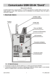
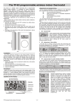
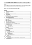
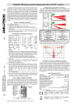
The GD-04 “David” GSM communicator User manual The GD-04 module got its name from David, a biblical king who outsmarted Goliath, a giant. In our case, Goliath is meant to be the GSM network. We hope that the skills of your tiny David will help you manage the giant. 1. Basic description GSM antenna Tabs SIM card SIM RESET jumper Bus connector LED indicator Battery connection Output fuses 1.1. David provides: 2 output contacts of power relays X and Y (each allows up to 5A/250V) 4 input terminals A to D for SMS reporting (the inputs react to a connection or disconnection to or from a common GND terminal) GD-04 DAVID 1 MKS51204 1.2. David can be used as: A switch with SMS remote control. SMS texts for switching particular terminals on/off are configurable. A time-switch which can be activated remotely via a mobile phone (the switch-on period is configurable from 1 second to 10 hours). A relay with dialling-in remote control. Up to 50 tel. numbers can be authorized for each relay. Because calls are not answered dialling-in control within GSM is free of charge. (David only checks the caller’s number and – if the number is authorized – responds with relay activation.) This can be used for parking latch control etc. A relay with validity-limited dialling-in remote control. Each authorized number can have a limit to the number of calls. When the call count reaches the limit the tel. number is deauthorized. This can be useful for pre-paid services such as e.g. parking. Any tel. number can be re-authorized via SMS by the administrator. An SMS reporter. Input A to D activations or deactivations can be reported by SMS and optionally confirmed by phone calls. Each input can have its own message texts and up to 8 tel. numbers programmed. Examples of David applications can be found on http://www.jablotron.cz/david/en/examples.htm 1.3. David can be supplemented with: A GD-04A back-up module, which provides David with the ability to work approx. 12 to 24 hours continually without an external power supply, (see 11.1). A GD-04D DTMF module, which allows you to control David’s output relays by entering numeric codes (DTMF codes) on the telephone keypad during calls, (see 11.2). A GD-04P link cable, which allows you to connect David to a PC through a USB port and perform any desired configuration using GDLink software (see 11.4). A GD-04R radio module, which allows input A to D activations via wireless buttons or detectors of the OASiS series and also provides David with the capability of output relay X or Y state transmission to UC or AC OASiS receivers. In addition, you can control relays X or Y “locally” via RC-8x keyfobs (so that an appliance can be controlled both via a mobile phone and a keyfob). The module also allows heating control (again locally or remotely via a mobile phone) using wireless thermostats of the TP-8x series (see 11.3). A detailed description of optional accessories can be found in chapter 11. 2. David’s SIM card In order to function, David needs a SIM card, preferably a tariffed one. Test the SIM card by using it in your mobile phone – SMS sending and calling must work correctly. Switch off the PIN code protection via the phone menu (or set the PIN code to 1234). Check the GSM signal strength in David’s location. 3. Installation 1. The GSM antenna should not be shielded by metals. If necessary, an external antenna designed for the 900/1800MHz GSM band can be connected via a 50Ω SMA connector. 2. Open the cover and release the electronic circuit board by pressing the tabs. 3. Mount the rear plastic cover at the desired location. 4. Insert a SIM card: Open the SIM card case by shifting the moving part in the direction of the terminals and tipping it off. Make sure that the card is correctly oriented and insert it. Close the SIM card case (fold and re-shift the moving part). GD-04 DAVID 2 MKS51204 5. Insert the circuit board back to its position. 6. Do the wiring, see below. 4. Wiring 1. Power supply – use the +12V and GND terminals (grey colour = +12V). Any power supply adapter used should provide 12V DC voltage and up to 500mA of current. Do not turn the power supply on until all input / output wiring has been done. 12V DC power supply _ + 2. Output relay contacts – available 230V/50Hz at the X1+X2 and Y1+Y2 terminals. Each contact is fused to 5A. The circuits which the contacts belong to are protected from the remaining electronics by a safety separator and are capable of switching up to Light bulb 2.5A at 250V AC. The following example shows a light bulb control via the Y output relay: 3. Input terminals – marked A to D. The terminals respond to a connection or disconnection to or from GND by sending an SMS report. No external voltage supply can be connected to these terminals – they can only be controlled via a potential-free switch/contact. Example of wiring a switch to input A: Switch 5. Initial powering up 1. Turn the power supply on, registering to the GSM network is indicated by the LED flashing (if no indication occurs, check the power supply wiring). 2. After GSM registration the LED stops flashing (usually within 1 minute). Continued flashing indicates a GSM registration fault. Disconnect the power supply and check that a valid SIM card has been correctly installed into the device, see 2 and 3). 3. Send the SMS instruction STATUS to David’s SIM card number. 4. David responds by a status report, e.g. STATUS: A0,B0,C0,D0,X0,Y0,GSM:80%, Vcc:12.2V (which means that all A to D inputs and both the X and Y relays are switched off, the GSM signal strength is 80% and the power supply voltage is 12.2V). Depending on the GSM network traffic the response may take some time. If no response occurs, verify that “STATUS” is spelt exactly right in the text of the message and that you are sending the message to David’s correct SIM card number (repeat the previous step). 6. Programming 6.1. Via the Internet The simplest way to program David is via the web site www.david.jablotron.cz. You fill in all the required parameters in a form on a single web page, press the Send button, and the Jablotron web server will forward the settings to your David via the GSM network. Performance of a successful transfer is confirmed from David by an SMS reply "PROGRAM OK" to your mobile phone. GD-04 DAVID 3 MKS51204 All parameters are sufficiently described on the page so that you do not need to use David’s installation or user manual to perform programming. Programming via the web site is free of charge. No user registration is required. Your David’s settings are not stored on the web server. Instead, you can save them as a file in your computer for future use (the file can then be imported to the page). The page does not allow you to retrieve the current settings of your David. Any programming is only possible if a valid access code (default = PC) is specified (the code, being a part of David’s settings, is not stored on the web server, only in your David). This makes the web access to your David both secure and simple. 6.2. Using a PC running GDLink software If you need to program David frequently, connecting David to a PC running specialized software is the recommended option. GDLink software allows you not only to send programming instructions but also to retrieve the current David settings. For the PC connection, you can use a GD-04P link cable connected to a USB port (the cable is supplied separately). GDLink software is available either in the GD-04P’s package or on the www.jablotron.com web site. 6.3. SMS instructions David can also be configured via SMS instructions from your mobile phone. The programming instruction format is explained in the following example: PC, ARX, heating on, DRX, heating off where: is the access (programming) code, required at the start of any programming SMS message* (2 to 8 ASCII characters, the factory default setting is PC) , is a comma separator ARX is the name of the instruction for programming the text you wish to use for switching relay X on via SMS. The desired text (“heating on”) follows, separated by a comma. DRX is similar to ARX, related to switching relay X off. The above SMS instruction tells David that the X relay can be switched on/off by the SMS instructions “heating on” / ”heating off”. Note: This text distinguishes between SMS messages and SMS instructions – an SMS message can contain multiple SMS instructions in a sequence. PC SMS instruction rules: 1. Any programming SMS message must start with a valid access code (the factory default code is PC). Multiple messages mean multiple codes. 2. A single message can contain multiple instructions. David is capable of long message processing – if enabled by your phone, you can write and send a programming SMS message containing up to 2400 ASCII characters. 3. The comma separator is used both between individual instructions and between individual segments within instructions. 4. Spaces are ignored, except in operational texts which are meant to be a part of a David setting. 5. The successful processing of a programming SMS is confirmed from David by the SMS reply “PROGRAM OK”. 6. When an error is encountered, David reports a “PROGRAM ERROR” followed by the text of the instruction which has not been recognized. Preceding instructions within the message are carried out, succeeding instructions are ignored. 7. David is not case sensitive (does not distinguish between lowercase and UPPERCASE letters). GD-04 DAVID 4 MKS51204 8. The use of accented characters is not recommended. 9. After an SMS message has been received, David switches off both the X and Y relays. 10. See table 1 for a brief instruction list. 7. Remote operation via SMS instructions When using texts which have been programmed for David SMS operation (relay control, status interrogation) the following conditions apply: David does not distinguish between authorized and unauthorized phones when processing operational SMS instructions. Instructions can be sent from any phones, but the texts must match the texts which have been pre-programmed (except the lowercase/UPPERCASE attribute). Access codes are NOT part of operational SMSes. A single SMS message can contain multiple instructions separated by commas, e.g. HEATING ON, LIGHTS OFF, STATUS David can be so configured that every instruction performance is reported by SMS. Received SMSes with unrecognised instructions can be forwarded to the so called service number (see table 1). If you are not sure whether any other text will be automatically added to the SMS on its way to David (for example, when using an SMS internet gate) type the message like this: %instructions%%. Example: The SMS text “1/1 www: %heating on%%” is interpreted as heating on. 8. Remote operation via dialling-in David allows you to control the X and Y relays via dialling-in from pre-authorised phones. If a call is made to David from a pre-programmed number, the call is rejected and the relay reacts as follows: o If a limit is set to the relay switch-on period then the relay switches on for the limit period. o If no limit is set (zero value is set for the limit) then the relay switches on permanently until a switch-off SMS instruction or another dialling-in event occurs. Notes: Up to 50 tel. numbers can be programmed for each relay. Each tel. number can have a limit to the number of calls so that any further calls are ignored. This feature is not applicable to phones with withheld numbers. Dialling-in relay control can be reported by SMS. 9. Using prepaid SIM cards Prepaid SIM cards are NOT recommended for use in David, because they increase the risk of David malfunctioning due to a possible credit balance under-run or expiration of the time limit. If you still decide to use a prepaid SIM card, you can configure David for periodic balance interrogation. If the reported credit balance is lower than the set limit, the credit balance message will be automatically sent to the service phone numbers. To program this feature you need to know some data specific to the GSM provider (see the SIM card documentation). The programming instruction is of the following form: PC, CRD, xxxx, dd, hhh, pp where: PC CRD xxxx dd hhh GD-04 DAVID is the access code is the name of the instruction for credit balance interrogation is the command string to ascertain the credit (GSM network specific, e.g. *104#) is the auto-interrogation frequency in days is the minimum acceptable credit balance 5 MKS51204 pp is the textual position at which the number showing the balance starts in the reply message from the GSM provider Example: If you require at least 50€ of credit balance, and the USSD code used to query the available balance is *104# and you want a weekly interrogation frequency, use the following instruction: PC, CRD, *104*#, 7, 50, 01 If you do not want automatic interrogation, you can program David to report the balance in response to your SMS instruction: PC, CRD . The programming is achieved by a programming instruction according to the following example: PC, CRD, *104*#, 0, 0, 0 Note: David’s SIM card balance interrogation may stop working due to changes in GSM services (e.g. a different response format). You should therefore be acquainted with the methods your GSM provider uses or will use for querying the available balance. 10. Reset to factory defaults You can reset David to the factory default settings via the SMS instruction PC, RST, where PC is a valid access code - see Table 1. Another option is to use the RESET jumper (next to the SIM case): a) Turn the power supply off (including the backup module if used). b) Connect the RESET jumper, turn the power supply on and disconnect the jumper after about 5s. Note: Performing a RESET erases all programmed tel. numbers and texts. 11. Optional accessories David’s functionality can be extended by optional modules or other separately supplied accessories: 11.1. The GD-04A back-up module This module is imbedded in a specially-enlarged replacement cover. Installation is performed by replacing the original cover, together with wiring the GD-04A module to the GD-04 circuit board via the corresponding connector. The backup battery requires approx. 72 hours to be fully charged. The battery provides approx. 12 to 24 hours of backup operation, depending on the output relay state and on the GSM signal strength (as with any GSM device, David’s consumption is higher in places with a low signal level as the transmitter power has to be increased). Only David’s electronics is backed up. No voltage is available on the +12V terminal during backup operation. Discharging the battery causes David to be switched off (including the X and Y relays). After the recovery of the main power supply David will switch on (but the relays stay switched off) and starts charging the battery. The message POWER FAIL or POWER RECOVERY is sent to the service number (STN). 11.2. The GD-04D DTMF module The GD-04D allows relay X and Y control by entering numeric codes (DTMF codes) on the telephone keypad during calls. The DTMF codes intended for use have to be programmed, see table 1. The module can be installed by plugging in to the appropriate digital bus connector after the power supply has been disconnected. GD-04 DAVID 6 MKS51204 11.2.1. DTMF relay control Call David’s tel. number. After about 7 seconds, David responds with a beep on the line (this means that the call has been answered) followed by relay X and Y status indication (in this order): 2 short beeps = OFF, 1 long beep = ON. Enter the DTMF code. A relay switch-on is confirmed by a long beep, a switch-off by two short beeps. Terminate the call (David automatically terminates the call after 60 seconds). After the call has been terminated David reports the current relay status via SMS. Note: Too weak a GSM signal in David’s or your location may result in DTMF control malfunctions. 11.3. The GD-04R radio module By plugging the GD-04R radio module into the digital bus connector (after the power supply has been disconnected) your David acquires the following capabilities: Relay X and Y state transmission to UC or AC OASiS wireless receivers. XY ABCD Input A to D activations via RC-8x OASiS wireless buttons or via JA8x OASiS wireless detectors. GD-04R module Relay X or Y control via RC-8x OASiS wireless buttons. Relay X or Y control via a TP-8x wireless thermostat. The module has a built-in internal antenna. If necessary, a Jablotron external antenna of type AN-80 or AN-81 can be applied to extend David’s remove it if working range. external antenna Note: The external antenna is always needed when the GD-04A back-up module is used. 11.3.1. Transmitting X or Y relay status to an UC-82 or AC-82 receiver Enter mode 4 on the receiver and press the XY button on David’s GD-04R module. This establishes a connection so that the receiver’s relay status mirrors David’s relay status. There is no limit to the number of UC/AC receivers which can be connected this way. 11.3.2. Wireless device input assignment and operation Each input A to D can have one OASiS wireless device assigned to it. This way, triggering an external wireless device has the same effect as GD-04 input activation by physical connection to GND, effectively making the inputs radio-signal-activated. Take the following steps to enroll a device: 1. Press and hold the ABCD button on the GD-04R module. 2. Entering enrollment mode is indicated after 5 seconds by flashing of the LED on the GD-04R module – release the button. 3. Enroll up to 4 wireless devices to the GD-04R (send enrollment signals to the module). The first device is assigned to the A input, the second one to the B input, etc. Wireless detectors are enrolled by inserting their batteries, for wireless buttons, see below,. Enrollment is confirmed by a long flash from the LED on the GD-04R. Important: Enrolling the first device erases all the previously enrolled devices. Thus all the desired devices should be enrolled in a single enrollment session. 4. Exit enrollment mode by pressing the ABCD button (enrollment is automatically terminated after the fourth device has been assigned or after 40 seconds). 5. After enrollment mode termination, the LED on the module lights for approx. 5 seconds to indicate enrollment data storage. Notes: If the two buttons A and B are present on an RC-8x controller, the device can be enrolled by pressing and holding both buttons at the same time for approx. 6 seconds. The operational GD-04 DAVID 7 MKS51204 logic is then as follows: pressing A or A+B is responded to by an SMS report about input activation (a connection to GND). Pressing the B button is responded to by an SMS report about input deactivation (a disconnection from GND). For single-button controls (such as the RC-87 or RC-89) the device can be enrolled by pressing and holding the button for approx. 6 seconds. Pressing the button is then responded to by an SMS report about input activation. Enrolled JA-8x detectors work with the following logic: o Input activation is reported by SMS in response to detector triggering (body movement, door opening, breaking glass, fire, tamper...) o Input deactivation is reported by SMS in response to panic signals or to the de-triggering of state-providing detectors (JA-8xM) Wireless devices can also be assigned by entering their production code using the LRN instruction. An input terminal with a wireless device assigned to it can be configured (see Optional functions, DIP parameter g) so that connection to GND disables the reception of wireless signals. This feature allows the setting/unsetting of enrolled detectors. 11.3.3. Controlling the outputs using an RC-8x wireless button unit Each X or Y output can have four OASiS wireless button units assigned to it. 1. Press and hold the XY button on the GD-04R module 2. Entering enrollment mode is indicated after 5 seconds by flashing of the LED on the GD-04R module – release the button. 3. Enroll up to 4 wireless button units to the X output (send enrollment signals to the module - see notes below). Press the XY button again to allow enrolling to the Y output. A change of flashing rate indicates this. Enrollment is confirmed by a long flash of the LED on the GD-04R. Important: Enrolling the first device erases all the previously enrolled devices. Thus all the desired devices should be enrolled in a single enrollment session. 4. Exit enrollment mode by pressing the XY button (enrollment is automatically terminated after the fourth device has been assigned or after 40 seconds). 5. After enrollment mode termination, the LED on the module lights for approx. 5 seconds to indicate enrollment data storage. Notes: If the two buttons A and B are present on an RC-8x controller, the device can be enrolled by pressing and holding both buttons at the same time for approx. 6 seconds. Button A then switches on an output, button B switches off an output and A+B changes (toggles) the status of an output (switch on – switch off). For single-button controls (such as the RC-87 or RC-89) the device can be enrolled by pressing and holding the button for approx. 6 seconds. Pressing the button then changes the status of an output (switch on – switch off). To delete all enrolled items, press and hold buttons XY and ABCD until two long flashes occur on the red LED. 11.3.4. Using David for heating operation and status reporting Each input A–D can have a wireless thermostat of the TP-8x series assigned to it (see 11.3.2). Enroll a thermostat to any of the A, B, C or D inputs to get reports about exceeding the maximum/minimum allowable temperature limits in your house: o Exceeding the upper temperature limit (e.g. 60°C) is responded to by an SMS report about input activation. o Dropping under the lower temperature limit (e.g. 3°C) is responded to by an SMS report about input de-activation. GD-04 DAVID 8 MKS51204 Enroll a thermostat to one of the A or B inputs to take control of the temperature in your house. An A-assigned thermostat controls relay X, a B-assigned thermostat controls relay Y. This way heating control is established, supplemented by the reporting described above. Thermostats enrolled to C or D inputs only provide reporting. Normally, an A- or B- enrolled thermostat switches the heating (via the X or Y relay) so that temperature comfort is maintained. However, you can put the heating in economic mode by sending an SMS instruction for switching relay X or Y on, which puts the heating back to normal mode. The same can be done by connecting the A or B input to GND. The thermostat will then only provide anti-freeze protection: the heating will be switched on when a critically low temperature is signalled (e.g. 6°C). Sending an SMS instruction for switching relay X or Y off puts the heating back to normal mode (with A or B disconnected from GND). If input A or B is used for thermostat enrollment, the status SMS report (obtained from David on an SMS request) contains information about the temperature. Example: STATUS:A0,B0,C0,D0,X1,Y0,GSM:70%,TA:25/24C,TB:22/22C, Vcc:12.2V where: TA labels data from thermostat A, TB labels data from thermostat B. The data is of the form maintained temperature / measured temperature. Enrolling a thermostat to the A or B input disables relay X or Y enrollments. DIP switch g setting has no effect on enrolled thermostat operation. To delete all enrolled items, press and hold buttons XY and ABCD until two long flashes occur on the red LED. 11.4. The GD-04P link cable The GD-04P cable allows you to link David with a PC through an USB port and perform any desired configuration using GDLink software. The software is supplied on a CD in the package together with all the necessary drivers. You can also download GDLink from www.jablotron.com. 11.4.5. Installing GDLink and the drivers 1. Connect the GD-04P cable to a free USB port on your PC and insert the CD into the CD drive. 2. Wait for “New Hardware Wizard“ to start up. 3. Search for the drivers on the removable medium (CD). 4. When installing for WIN XP, ignore the notification about wrong authenticity with WIN XP and continue with the installation process. Leave the other parameters without any modifications. 5. Finish the new hardware installation wizard process. 6. There are two devices contained in one, so please wait for the “New hardware wizard” to start again. Repeat the procedure according to steps 3 to 5. 7. Your PC now has two new devices after successful installation - "Jablotron serial interface" as a serial port (COM) driver and the USB device with the same name as the driver for USB. 8. Install the GDLink software on your PC. 9. Connect the GD-04P cable into David’s digital bus connector. GDLink is now ready to be started. 11.4.6. Using GDLink The program allows for: o Retrieval and modification of David settings. o Displaying the last 127 memorized events. o Relays X and Y direct control. o Inputs A to D status display. A comprehensible help option is provided as a part of the program. GD-04 DAVID 9 MKS51204 12. Specification Power supply Stand-by consumption Max. consumption (during communication) GSM band RF output power A, B, C and D input terminals Output contact rating X1,X2 a Y1,Y2 Resistive load Inductive (capacitive), lamp load Can be operated according to Safety EMC Radio transmissions Environment Dimensions (without antenna) GSM antenna 11 – 13 V DC approx 20 mA 500 mA E-GSM 850 / 900 / 1800 / 1900 MHz 2 W for GSM 850 / 900, 1 W for GSM 1800 / 1900 activated by a connection to GND max. 2,5A / 250V AC max. 0,5A / 250V AC ERC/DEC/(94)01 EN 60950-1 EN 301489-7, EN 55022 and EN 50130-4 ETSI EN 301419-1 and EN 301511 II. indoor general (-10°C to +40°C) 76 x 110 x 33 mm connected to SMA connector JABLOTRON ALARMS a.s. hereby declares that this product is in compliance with the essential requirements and other relevant provisions of Directive 1999/5/EC. The original of the conformity assessment can be found on the web site www.jablotron.com, Technical Support section. Note: Although this product does not contain any harmful materials we suggest you return the product to the dealer or directly to the manufacturer after use. GD-04 DAVID 10 MKS51204 David’s settings Input’s SMS reports SMS when activated SMS when deactivated Input A Phone numbers SMS when activated SMS when deactivated Input B Phone numbers SMS when activated SMS when deactivated Input C Phone numbers SMS when activated SMS when deactivated Input D Phone numbers Relays operation Relay X Relay Y ON command OFF command Tel. numbers authorized for relay control ON command OFF command Tel. numbers authorized for relay control SMS: SMS: DTMF code: *) DTMF code: *) SMS: SMS: DTMF code: *) DTMF code: *) *) Only available for the GD-04D version Wireless items *) Enrolled Input A Input B Input C Input D Relay X Relay Y GD-04 DAVID Type Device code Place *) 11 Only available for the GD-04R version MKS51204 Table 1 – A brief list of programming SMS instructions Any programming SMS message must start with a valid access code (see 6.3). Example: PC, ARX, heating on, DRX, heating off Instruction Function Factory default Description Relays X and Y operation SMS to switch relay ON ARX, xxx..x SMS to switch relay OFF DRX, xxx..x Relay switch-on period TMX, t..t Telephone numbers authorised for relay control ADX, x..x,x..x Telephone numbers authorised for relay control with a validity limit. LDX, x..x,n, x..x,n Erasing tel. numbers authorised for relay control EDX, x..x, x..x Use ARY for relay Y. xxx..x = text (up to 30 characters), text erased by ARX, , Example: ARY,ventilator on Use DRY for relay Y. xxx..x = text (up to 30 characters), text erased by DRX, , Example: DRY,ventilator off erased erased Use TMY for relay Y. t..t = switch-on period in seconds, or zero 1 to 10h entered in seconds, minutes(m) or hours(h) (3600s = 60m = 1h) The relay works as a time-switch, activated via switch-on SMSes or dialling-in. Deactivation is by time-limit expiration or via switch-off SMSes. 0: no time-limit applies, dialling-in is responded to with toggle logic: on – off – on… Use ADY for relay Y. x..x = tel. number. Up to 50 numbers can be entered (in a single instruction or gradually). The numbers are added to the list of authorised numbers. Example: ADX, 777123456, +420608503211 authorises two new numbers for relay X control. Use LDY for relay Y. x..x = tel. number. The numbers are added to the list of authorised numbers, up to 50 in total. n = limit in the number of calls (1 to 99), exceeding the limit removes the number from the list – this is reported to the service number by SMS. Example: LDX, 777123457, 31 authorises a new number for relay X control for a maximum of 31 calls. Use EDY for relay Y. x..x = tel. number. The 0 (no limit) empty list – numbers (up to 50) are removed from the list. Example: EDX, 777123457 de-authorises a single tel. number used for relay X control. Input A to D activation/deactivation SMS reports Input activation text ATA, xx..x Use ATB for input B, etc. Input deactivation text DTA, xx..x Use DTB for input B, etc. Telephone numbers for input reports TNA, x..x, x..x Use TNB for input B, etc. Input-event calls DNA, n GD-04 DAVID xxx..x = text (up to 30 characters*) Example: ATC, heating on Instruction ATA , , erases the text = no reports xxx..x = text (up to 30 characters*) Example: DTC, heating off Instruction DTA , , erases the text = no reports x..x = tel. number, up to 8 for each input. All previously stored numbers are erased. Use TNA, to empty the list. Example: TND, 777123456, 608123456 sets David to report input D events to 2 numbers Use TNB for input B, etc., n = 1 (ON), 0 (OFF). If set to ON, every SMS report is followed by a call. If you answer the call, you hear a constant tone = activation, or an interrupted tone = deactivation. Example: DND, 1 12 A1, B1, C1, D1 A0, B0, C0, D0 empty list OFF MKS51204 Additional functions xx…x = new access code, 2 to 8 characters Example: NPC, MARTIN27 xxx..x = text, up to 30 characters Example: STS, HOW ARE YOU NOW xxx..x = tel. number. Up to 2 numbers can be set, previously set numbers are erased. Service numbers are used to report faults: POWER FAIL / POWER RECOVERY 1 LINE OK (GSM signal recovery) THERMOSTAT FAILED lost communication LOWBATT low battery in any wireless device Other events – see Optional functions. Instruction STN, erases service number(s). Parameter a to f values can be: 1=ON, 0=OFF, x=unchanged Description of the parameters: a Forward unrecognised SMSes to the service number (including phone number) b Periodic calls to the service number every 24 hours (from the moment of being set) c Forward all SMSes to the service number d Max. 10 SMSes within 15 minutes (all subsequent SMS requests ignored) e SMS reporting of relay dialling-in-control f SMS reporting of relay SMS control (e.g. heating off OK) g Input terminal GND connection disables any wireless connection to the input (not applicable to thermostats) Example: DIP,1,x,x,x,x,1,x Use CAY for relay Y. xx..x = numeric code, up to 8 digits Example: CAY, 1234 Instruction CAY, erases the code. Use CDY for relay Y. xx..x = numeric code, up to 8 digits Example: CDY, 1234 Instruction CDY, erases the code. n = A, B, C, D, X or Y (input or output the device should be assigned to) xx..x = device production code (last 8 digits) Only one device can be assigned to each A to D input, whereas each of X or Y relays can have up to 4 devices enrolled. Example: LRN,A,xx..x,B, xx..x, X,xx..x Instruction LRN, erases all assignments. A device cannot have multiple assignments. The order of A to Y is arbitrary, no duplications are allowed. New access code NPC, xx…x SMS to get David’s status STS, xx..x Service tel. numbers STN, x..x, x..x Optional functions DIP,a,b,c,d,e,f,g DTMF code to switch relay ON2 CAX, xx..x DTMF code to switch relay 2 OFF CDX, xx..x Wireless device assignments3 LRN,n,xx..x,n,x. Triggering re-registration to the GSM network GSM David will unregister and then re-register to the GSM network. This can be useful after a blocked SIM card has been unblocked. A re-registration is also triggered by briefly connecting the RESET jumper while David is being powered up. Reset RST Resets David to the factory default settings. This can also be performed by connecting the RESET jumper during powering up – disconnect the jumper after approx. 5 sec. 1 2 3 Only available for the GD-04A version Only available for the GD-04D version Only available for the GD-04R version PC STATUS none 0000000 (all OFF) none none none JABLOTRON ALARMS a.s. Pod Skalkou 4567/33 46601 Jablonec nad Nisou Czech Republic Tel.: 483 559 911, Fax: 483 559 993 Internet: www.jablotron.cz