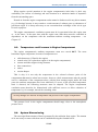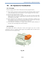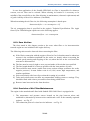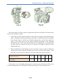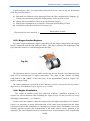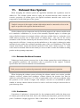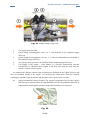
1
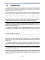
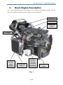
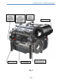
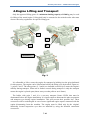
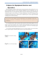
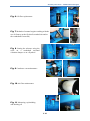
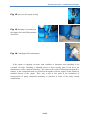
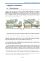
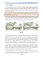
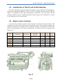
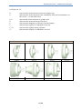
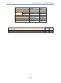
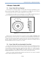
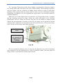
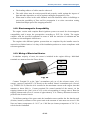
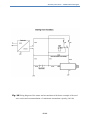
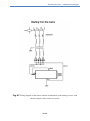
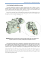
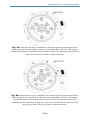
Stationary Gas Engines ASSEMBLY INSTRUCTIONS for partly completed machinery TEDOM a.s., Division ENGINES Belgická 4685/15 466 05 Jablonec nad Nisou Czech Republic www.tedomengines.com Assembly instructions – TEDOM Industrial Engines 1.Contents 1. Contents .............................................................................................................................. 2 2. Introduction ........................................................................................................................ 4 3. Basic Engine Description ................................................................................................... 5 4. Engine Lifting and Transport ............................................................................................. 7 5. Space for Equipment Service and Operation ..................................................................... 8 6. Engine Installation............................................................................................................ 11 6.1. Flexible Mounting ..................................................................................................... 11 6.2. Tight Fit ..................................................................................................................... 12 6.3. Combinations of Tight Fit and Flexible Mounting .................................................... 13 6.4. Engine's Centre of Gravity ........................................................................................ 13 6.5. Rear Cover Loading................................................................................................... 14 6.6. Torsion Diagram ........................................................................................................ 14 7. Power Take-Off ................................................................................................................ 17 7.1. Power Take-Off from Flywheel ................................................................................ 17 7.2. Power Take-Off from Crankshaft's Front End .......................................................... 17 8. Engine Compartment Arrangement ................................................................................. 18 8.1. Engine Operation Environment Characteristics ........................................................ 18 8.2. Spatial Arrangement .................................................................................................. 18 8.3. Temperature and Pressure in Engine Compartment .................................................. 19 8.4. System Dimensioning ................................................................................................ 19 8.5. Noise .......................................................................................................................... 20 9. Engine Cooling System .................................................................................................... 21 9.1. General Rules ............................................................................................................ 21 9.2. Cooling Circuit Assessment ...................................................................................... 22 9.3. Systems with External Water Pump .......................................................................... 23 9.3.1. System with Filling Mixture Intercooler ............................................................ 24 9.3.2. System without Filling Mixture Intercooler ....................................................... 25 9.4. Systems with Motor-Operated Water Pump .............................................................. 26 9.5. Coolants ..................................................................................................................... 27 10. Air System for Combustion........................................................................................... 28 10.1. Air Intake ............................................................................................................... 28 2/ 49 Assembly instructions – TEDOM Industrial Engines 10.2. Air Filter................................................................................................................. 28 10.3. Pure Air Line.......................................................................................................... 29 10.4. Provision of Air Filter Maintenance ...................................................................... 29 10.5. Biogas Fuelled Engines .......................................................................................... 31 10.6. Engine Ventilation ................................................................................................. 31 11. Exhaust Gas System ...................................................................................................... 33 11.1. Exhaust Gas Back Pressure .................................................................................... 33 11.2. Condensate ............................................................................................................. 33 12. Fuel System ................................................................................................................... 35 12.1. Fuel Properties ....................................................................................................... 35 12.2. Gas Analysis .......................................................................................................... 35 12.3. Fuel Route Design .................................................................................................. 35 13. Engine Lubrication ........................................................................................................ 38 14. Wiring............................................................................................................................ 40 14.1. Principles................................................................................................................ 40 14.2. Electromagnetic Compatibility .............................................................................. 41 14.3. Wiring of Electrical Starter .................................................................................... 41 14.4. Setting the ignition system ..................................................................................... 44 15. Engine Storage .............................................................................................................. 47 16. Abstract of declaration of incorpora -tion ..................................................................... 47 17. Additional Information .................................................................................................. 48 17.1. List of Associated Documents ............................................................................... 48 17.2. Last Revision Date of Actual Edition .................................................................... 48 3/ 49 Assembly instructions – TEDOM Industrial Engines 2. Introduction This assembly instructions is purported to provide the basic hints and recommendations for the installation of the TEDOM stationary gas industrial engines. Adherence to these principles is prerequisite for the maintenance of the manufacturer's warranty, long service life of the equipment, and trouble free and safe operation. Before commencing the work please pay attention both to the entire present document and further documents that are referred to below in this text. It must be emphasized that the combustion engine in general is a complex equipment with a series of dangers where possible hazards can never be totally eliminated or reduced to the level presenting no jeopardy for health. It is therefore necessary that the manufacturer of the complete machinery or its keeper prevents the access near the equipment for all the unauthorized personnel. Only such person can be charged with any work on the equipment who is demonstrably trained, who has the adequate technical qualification, and has read and understood the provided documents. Adherence to the safety regulations and general rules for the prevention of injuries to personnel as well as observance of the local applicable laws and standards are a must in the process of installation and operation. The declaration of incorporation of partly completed machinery gives a list of the applied and fulfilled basic requirements for the protection of health and safety. Engine (the incomplete machinery) cannot be considered safe until all the requirements have been complied with. Then it is necessary to assess all the risks arising from installation of engine into the final machinery and adopt the necessary protective measures to eliminate such risks (for further information see Chapter 16). The unceasing development of TEDOM engines aimed at the improvement of parameters, service life and operator comfort, as well as the process of engine adaptation to specific requirements of a customer may cause that the illustrations given in this Manual do not always reflect the reality. Despite this, the information stated herein may be considered generally valid. The reference to the engine's Technical specification occurs frequently in the text below. The document applicable for the values contained in the Technical specification is the internal guideline Terms of validity of technical specifications for TEDOM gas engines no. 61-0-0284. The equipment must not be modified or altered without the written consent of TEDOM a.s. Division Engines, the manufacturer! These assembly instructions together with the declaration of incorporation will become an integral part of the technical documents to this machinery after the installation into the complete machinery. 4/ 49 Assembly instructions – TEDOM Industrial Engines 3. Basic Engine Description The version illustrated herein corresponds to the standard supercharged engine with the intercooler and Bosch ignition system (engine series 849 and 850). Throttle valve Mixer Exhaust gas outlet Gas supply Coolant inlet and outlet (stage 2) Coolant inlet (stage 1) Vessel for separated oil (from crankshaft ventilation) Fig. 1 5/ 49 Full-flow oil filter Assembly instructions – TEDOM Industrial Engines Engine cabling attachment connector e Oil filling Location of engine identification data (number and plate) Coolant outlet (stage 1) Air intake Centrifugal oil filter in bypass Oil drainage Fig. 2 6/ 49 Assembly instructions – TEDOM Industrial Engines 4.Engine Lifting and Transport Only the approved lifting gears of a minimum loading capacity of 1200 kg may be used for lifting of the actual engine. Lifting shall only be entrusted to the trained worker who must observe the safety regulations for specific lifting gear. 5 1 3 2 4 Alternative 5 Fig. 3 It is allowable to lift or secure the engine for transport by holding it at the grips dedicated for this purpose. The engine can be lifted when held by the lifting eyes depicted on Figure no. 3, points 1 and 5. The other points (2, 3 and 4) are intended exclusively to assure the engine's stability during transport. What can be further secured during transport is only the transport means the engine is placed upon (throw-away wooden pallet or steel frame). The holder with grips 3 and 4 is a one-way transport fixture N2524 that must be dismounted before the engine installation. It is inconvenient to dismount the other suspension and transport eyes during engine installation. This will prevent their possible loss. These accessories will be needed again in case of more significant engine repairs connected with the engine dismounting from the machine. The engine must be lifted only by the original, identically located suspension eyes that are installed by using the identical connection accessories. 7/ 49 Assembly instructions – TEDOM Industrial Engines 5.Space for Equipment Service and Operation When the engine is installed, sufficient space must be ensured to allow problem free access for the equipment operator (see the Instruction Handbook) and for maintenance (see the Maintenance plan). The area around the engine must allow movement of the operating and maintenance staff at a safe distance from the hot components. When planning the free space around the engine it is also necessary to consider minimization of the risk of stumbling with consequent fall. What must be assured next is sufficient space for the engine movement resulting from its flexible mounting. An easy access to the engine will allow minimization of the maintenance related costs, reduction of downtimes, and limitation of the hazards associated with operation and maintenance. It is advisable that the frame structure allows removal of the bottom engine cover (oil sump) or at least its lowering by a min. of 270mm. Then it should allow for the removal of the intake, exhaust, and water pipe as well. If this is impossible, certain more demanding engine repairs will require that the engine is removed from its site. A set of figures depicting graphically the access to certain common service tasks follows below. Specific engine version may differ from the version described herein! Fig. 4 Valve clearance setting methods Fig. 5 Access to the spark plugs 8/ 49 Assembly instructions – TEDOM Industrial Engines Fig. 6 Oil filter replacement Fig. 7 Methods of manual engine cranking with the use of fixtures (at the flywheel's toothed rim and at the crankshaft's front end) Fig. 8 Setting the advance using the scale on a crankshaft torsional vibration damper or on a flywheel Fig. 9 Crankcase vent maintenance Fig. 10 Air filter maintenance Fig. 11 Measuring, replenishing and draining oil 9/ 49 Assembly instructions – TEDOM Industrial Engines Fig. 12 Access to the engine wiring Fig. 13 Draining of coolant from the engine block and filling mixture intercooler Fig. 14 Centrifugal filter maintenance If the engine is equipped ex-works with ventilator or alternator, their guarding is not executed ex-works. Guarding or disabled access to these moving parts is left up to the manufacturer of the complete machinery. The reason is the need for fastening such guards or features to the components that are not delivered together with the engine or that cannot be installed directly to the engine. Thus, only a part of this point in the declaration of incorporation of partly completed machinery is satisfied in terms of the safety related requirements. 10/ 49 Assembly instructions – TEDOM Industrial Engines 6.Engine Installation 6.1. Flexible Mounting It is used for the motor-generator sets of a single-bearing type. Generator is mounted with a flange to the engine rear cover and the assembled genset is connected to the frame or foundation via 4 silentblocks (two silentblocks in the engine front end, two silentblocks under the generator). Tuning of the actual oscillation frequency to be significantly lower (by 40 % as minimum) than the main excitation frequency is the key factor for the correct operation of this type of mounting. In the four-stroke engines, this frequency is 12,5 Hz (at a speed of 1500 rpm) or 15 Hz (at 1800 rpm). Fig. 15 The actual frequency drops with the rising genset weight and it rises with the rising rigidity of the silentblocks. With specific genset weight, the silentblock rigidity is therefore the essential parameter. The soft silentblocks will provide actual frequency that is low, however, what must be taken into account on the other hand is a high amplitude of the entire genset's oscillations, namely when critical speed is being overcome (genset starting and stopping), under abrupt changes to the load or in fault conditions (spark failure, etc.). The frame structure must be very rigid so that it has a minimum influence on the behavior of a flexible mounting system. Silentblocks must be deployed so that they are loaded evenly with regard to the genset's centre of gravity. All the pipes (exhaust, coolant, gas) must be connected using the flexible elements. Their operating range must respect the real oscillation amplitude of the genset in flexible mounting. Inconvenient flexible elements (for example, excessively rigid bellows) or their insufficient working range may result not only in the reduction of their service life but also in a damage to the follow-up engine components (turboblower, water pipe, intercooler, mixer, and so on). Opportune damage to any of the elements of mounting will fundamentally influence behavior of the entire flexible system and it may lead to large-scale damages so this is the reason why the genset must be stopped immediately in such a case. 11/ 49 Assembly instructions – TEDOM Industrial Engines 6.2. Tight Fit It is generally used for the set of engine - flexible coupling - appliance (dual-bearing generator, pump, compressor, etc.). In such a case the engine and appliance shall be fixed to the frame or foundation without any silentblocks. The engine must be fixed in four points (two brackets in the engine block's front end in a manner similar to the flexible mounting, two brackets at the rear cover). The brackets used for flexible mounting cannot be applied for fastening. This requires brackets that are much more rigid. If customer requests delivery of the engine with the brackets for tight fit, their design and execution must be discussed for specific situation. The appliance is fixed to the frame or foundation using feet or different connection points specified by the manufacturer. Fig. 16 The essential factors for the correct operation of the set with this type of mounting are rigidity and precision of the frame or foundation. The actual frequency of the set is given namely by the structure of brackets and frame and it must be much higher than the engine's excitation frequency (the higher harmonic components inclusive). The further very important factor is alignment of the set (both the alignment and admissible mutual angle of appliance and engine axis is usually determined by the coupling manufacturer). We recommend application of standard elements for the alignment (shim blocks, threaded adjusting elements). It is necessary to prevent introduction of the assembly tension into brackets and frame. The similar way as in the flexible mounting, all the pipes must be connected by the flexible elements. Unlike of the flexible mounting, the oscillation amplitude of the set or individual connection points is much lower and attention must be paid to the thermal expansion. Even in the tight fit, the suitably selected flexible elements must be used to prevent overloading of the follow-up engine components (turboblower, water pipe, intercooler, mixer, etc.). Occasional loosening of screw connections in the mounting, occurrence of cracks in the critical points of brackets or frame, etc., all of this may lead to large-scale damages so this is the reason why the set must be stopped immediately in such a case. 12/ 49 Assembly instructions – TEDOM Industrial Engines 6.3. Combinations of Tight Fit and Flexible Mounting The frame with firmly connected engine and appliance can be attached to the foundation or further frame through silentblocks. In such a case, the principles described in the Tight Fit chapter are applicable for the engine and appliance connection to the "top frame" and the principles described in the "Flexible Mounting" chapter apply for the attachment of created set to foundation or the "bottom frame". 6.4. Engine's Centre of Gravity If we place the coordinate system so that its origin is situated at the intersection of the crankshaft axis and the plane that passes through the points of front engine mounting, the position coordinates of the engine's centre of gravity will then correspond to the data in the table below (depending on the engine configuration). The direction of axes is apparent from Figure no. 17. Variant no. Turboblower Intercooler Air filter SPP1200L X [mm] Y [mm] Z [mm] 1 + + + 550 60 150 2 + + - 525 65 140 3 + - - 485 15 160 4 + - + 500 10 175 5 - - - 480 5 155 6 - - + 500 15 170 Fig. 17 13/ 49 Assembly instructions – TEDOM Industrial Engines 6.5. Rear Cover Loading The permissible loading of the rear cover by bending moment at the joint of engine and driven accessories is stated in the table below: For all the engines My [Nm] Mz [Nm] ≤4500 ≤5000 Fig. 18 6.6. Torsion Diagram Fig. 19 14/ 49 Assembly instructions – TEDOM Industrial Engines On Figure no. 19 : J0 J1 represents the inertia moment of torsion damper ring represents the inertia moment of the crankshaft's front end in dependence on the version – see the table below represent the inertia moment of cylinder unit represents the inertia moment of flywheel represents the damping coefficient of torsion damper represents the rigidity of crankshaft's front end represents the rigidity among cylinders represents the rigidity of crankshaft's rear end J2-J7 J8 k C1 C2-C6 C7 J1 [kgm2] 0.0462 0.0519 0.1075 0.2727 0.1618 0.3265 15/ 49 0.1222 Assembly instructions – TEDOM Industrial Engines J0 J2 – J 7 J8 k C1 C2 – C6 C7 SAE 11 ½ SAE 14 0.0840 0.1140 2.3750 2.0737 86.300 2.132 x 10⁶ 2.8700 x 10⁶ 4.4240 x 10⁶ Reduced weight of the rotary masses of one cranking (without any counterweights) Rotary proportion of con rod Weight of the sliding masses of one cranking 16/ 49 kgm2 kgm2 kgm2 kgm2 Nms/rad Nm/rad Nm/rad Nm/rad 6.71 kg 3.70 5.11 kg kg Assembly instructions – TEDOM Industrial Engines 7.Power Take-Off 7.1. Power Take-Off from Flywheel The total power of stationary engines is usually taken off from the crankshaft's rear end, that is, from the engine flywheel. This is in standard size of SAE 11½ or 14. Different versions dependent on the specific engine configuration are also possible. As standard, the rear engine cover corresponds to a size of SAE 1. Specific dimensions of rear cover and flywheel can be found in the installation drawings to the engine. Fig. 20 Rear cover and flywheel (SAE 11 ½) Engine must be connected with the driven equipment so that the engine crankshaft's axial play is not taken up. At the same time, it is necessary to assure that the play is not taken up as a result of the forces generated under operation (axial forces from the attached equipment or thermal expansion). Implement the engine and generator connection in harmony with the Internal Guideline Generator Assembly no. 61-0-0285. 7.2. Power Take-Off from Crankshaft's Front End In cases when partial power must be taken off from the front end of crankshaft (from the torsion damper), this fact must be known in advance and the engine must be adapted for such version (different crankshaft termination, engine fitted with a pulley, etc.). If this prerequisite is met it is possible to take off up to 50 kW of the engine's total power (at the rated speed) from the front end if not stated otherwise in the relevant Technical Specification. If this is not a genset operating in the constant speed mode, this case must be consulted with the Engineering Department of TEDOM. 17/ 49 Assembly instructions – TEDOM Industrial Engines 8.Engine Compartment Arrangement 8.1. Engine Operation Environment Characteristics The engine is designed for the operation in the area completely sheltered from the exteriors where the action of precipitation, flowing or splashing water and direct solar radiation are all eliminated. Neither prolonged influence of water vapour condensate nor abrasion influence may take place in this area. It is also necessary to eliminate the action of substances with a strong corrosive aggression. In terms of classification of the biological conditions, the presence of environmental factors (flora, fauna) is not considered. It is essential to pay attention to the clean state of engine in the areas with higher dust load since higher dust deposition on the hot engine components poses a risk of fire. The engine is not adapted to be operated in the explosive environment. 8.2. Spatial Arrangement As a consequence of the operation of engine and further associated devices, the ambient air is heated. It is therefore necessary to provide an efficient ventilation system of the engine compartment. The general rule applies that only fresh air without any admixtures of exhaust gas or heated waste air must be used for these purposes. This is why a convenient conception must be employed to ensure that these gases will not be taken in or that the aspirated air will not be heated as a result of a near-by exhaust line. Cold air must be preferentially conveyed to the generator (if a genset is in question) and to the intake port of engine's air filter. Figure no. 21 depicts the recommended air flow direction in the container box with the genset and engine's air filter. Fig. 21 18/ 49 Assembly instructions – TEDOM Industrial Engines What requires special attention in the engine compartment's inlet holes is their easy availability (for reasons of cleaning) and such location as to minimize intake of impurities from the surrounding space. Heated air from the engine compartment outlet cannot be further used in any direct manner (e.g. for heating) because it may contain a certain amount of exhaust gases or substances of petroleum origin. It is always necessary to use convenient heat exchanger of the air-air type for such a purpose. The engine compartment's ventilation system must be in operation before the engine start or - at the latest - at the same time with the engine start. Shut-down must be controlled in dependence on the compliance with the maximum ambient working temperature – see Chapter 8.3. 8.3. Temperature and Pressure in Engine Compartment The engine compartment's ambient temperature must not exceed 80°C. The most hazardous engine components in terms of temperature are: cable harnesses (if fitted in the engine) control unit (if it is placed on engine or in the engine compartment) sensors and other engine wiring elements hose connections starter torsion damper This is why it is not only the temperature in the selected reference point of the compartment that must be taken into account - however, check measurements must be carried out for a minimum of the components above with the heat running engine under full load (once the ambient temperature has been stabilized). If excess of the specified temperature limit is detected, the following measures must be adopted. The engine compartment ventilation must therefore be dimensioned with sufficient reserve to allow reduction of temperature by, for example, altered fan switching value. No step changes are allowed in temperature and pressure in the engine compartment. prostoru. The pressure level in the engine compartment should range close to the atmospheric pressure level. 8.4. System Dimensioning The most significant amount of heat is generated by the radiation from engine. The amount of air necessary to remove this heat can be established using the formula below: 19/ 49 Assembly instructions – TEDOM Industrial Engines 𝑉= V Q cp Δt ρ 𝑄 × 3600 𝑐𝑝 × ∆𝑡 × 𝜌 required air flow [m3/h] heat power of radiation [kW] (stated in the Technical Specification to the concerned engine) specific calorific capacity of the air [kJ/kg.K] temperature difference between the engine compartment and its vicinity air density [kg/m3] The total required amount of air is determined by totaling the amount of air required to remove the heat generated by radiation and the amount of air necessary for combustion. It is further necessary to calculate the amount of air required to cool down the generator (see the manufacturer's documents). If further equipment to remove exhaust gases (heat exchangers, exhaust conduits, dampers) are placed in the engine compartment, they must be taken into account as well. 8.5. Noise The acoustic pressure level of specific engine is given by relevant technical specification. The selected installation method (the container or another version) and the machine location both have a considerable influence on the noise level of the complete machinery. When selecting the operator station it is necessary to take into account both the high noise level as well as the inevitable movement of any persons near the operated machine. A self-adhesive label that warns of a high noise level, that is, draws attention to wear the ear protectors, is located on a clearly visible place of the engine. 20/ 49 Assembly instructions – TEDOM Industrial Engines 9.Engine Cooling System The TEDOM engines are liquid cooled engines with enclosed forced coolant circulation. The common version features a circuit equipped with the external circulation pump (it is not included in the engine delivery), however, the engine can also be optionally fitted with the centrifugal water pump with a belt drive from the crankshaft. 9.1. General Rules The required coolant flow through the engine as well as further circuit parameters are always specified in the Technical Specification to relevant engine. There you can also find the engine pressure loss-coolant flow chart, and if the engine is equipped with a filling mixture intercooler you can find the intercooler low-temperature and high-temperature segment pressure loss chart in dependence on the fluid flow there as well. The engine cooling circuit must necessarily be equipped with continuous temperature monitoring feature (the engine can be optionally fitted with relevant sensor at the coolant's exit from the engine). The circuit operating temperatures are specified in the relevant Technical Specification. When the maximum limit value of the coolant temperature 102°C - is exceeded, the equipment must be shut down (if not stated otherwise by relevant engine's Technical Specification). Cooling circuit's structural design must not allow occurrence of pulsations during operation and system aeration. The manual air-relief valves located on the engine (water collector pipe or, if necessary, engine's inlet socket or filling mixture intercooler or thermal controller case) are used only for deaeration when the engine is filled with a new cooling liquid. The circuit must be equipped with the venting line for continuous deaeration of the system under operation. All the necessary air venting lines must be reduced with the Ø4x10mm orifice gauge. To limit the ineffective flows to a maximum extent by bleeding of air, these points should be firstly connected and then reduced with orifice gauge. The line must rise continuously at its entire length. Total deaeration of system has to take place within 30 minutes of operation at the latest (visual inspection of bubbles in the glass tube). Ensure a space (expansion tank) in the cooling system that equals a min. 10% of the total amount of coolant in the circuit. This shall be used for coolant expansion and as a reserve volume to ensure reliable flooding of all the inner areas. Expansion tank must be equipped with a low level indication feature capable of shutting down the equipment (when, for example, the level drops abruptly as a result of an accident in the pipeline). The 21/ 49 Assembly instructions – TEDOM Industrial Engines interconnection of tank and circuit must be assured with a pipe of 25 mm in diameter that must be placed upstream of the water pump intake, preferably in the lowest point of system. No vacuum may be generated upstream of the coolant pump (a risk of cavitation)! It generally applies that the cross section of the connected pipes must not be lower than the cross section in the specific engine connection point. The pipe routing must prevent the creation and gathering of air bubbles (gradient, elevated points without deaeration, etc.). If the engine is mounted flexibly, also the pipe connection to engine must respect the amplitude range of the set's oscillation in silentblocks and the system's thermal expansivity. If rubber elements (hoses) are used, their length must be as short as possible and the execution must ensure stability of the shape. And last but not least, a complete drainage of the system must be assured. The recommendation to charge the cooling circuit with coolant from under is given in the Engine User Manual. This measure results in simpler system deaeration. When installing the engine, this measure must therefore be taken into account by creating the connection point in the lowest point of the system. This point must be fitted with a valve for easier and safer connection and disconnection of the feed and discharge piping. Suitable measures must be adopted to ensure purity of coolant. 9.2. Cooling Circuit Assessment The formula below represents the basic dependence between the assessed quantities: 𝑄= 𝑐𝑝 × 𝑚 × ∆𝑡 3600 Q amount of removed heat [kW] cp specific calorific capacity [kJ/kg.K] m coolant's mass flow rate [kg/h] Δt temperature difference at the engine inlet and outlet The resultant temperature gradient between the coolant inlet and outlet on the engine (in the engines with intercooler and relevant intercooler segment) should be within 3-7 °C. 22/ 49 Assembly instructions – TEDOM Industrial Engines What applies for the specific calorific capacity value is the formula according to the following chart: c [kJ/kg.K] 5 4 3 2 0 10 20 30 40 50 60 Concentration of antifreeze and anti-corrosion agent [% of volume] Fig. 22 9.3. Systems with External Water Pump The design of actual water pump must respect the compliance with the requirements imposed by the engine's Technical Specification (flow rate, removed heat, …) even in the least favorable admissible state. We recommend to maintain the constant temperature of the back flowing coolant by the installation of a three-way valve with automatic temperature control. The pump should be placed in the circuit directly upstream of the inlet into engine. 23/ 49 Assembly instructions – TEDOM Industrial Engines 9.3.1. System with Filling Mixture Intercooler The maximum admissible fluid service pressure in the secondary circuit (low-temperature segment of intercooler) amounts to 600 kPa. This system must not be interconnected with the primary circuit (high-temperature segment of intercooler) that is intended to cool down the engine and is taking part in the process of filling mixture cooling. Fig. 23 1 2 3 4 5 6 7 8 9 Coolant inlet Coolant outlet Pump Expansion tank with low level indication Filler neck with overpressure plug (-10kPa / +70±10kPa) Profile throttling (see Chapter 9.1.) Venting line (see Chapter 9.1.) Inlet for engine coolant (high-temperature segment) Fluid inlet and outlet of the secondary circuit (low-temperature segment) – inlet and outlet can be interchanged. 24/ 49 Assembly instructions – TEDOM Industrial Engines 9.3.2. System without Filling Mixture Intercooler Fig. 24 1 2 3 4 5 6 7 Coolant inlet Coolant outlet Pump Expansion tank with low level indication Filler neck with overpressure plug (-10kPa / +70±10kPa) Profile throttling (see Chapter 9.1.) Venting line (see Chapter 9.1.) 25/ 49 Assembly instructions – TEDOM Industrial Engines 9.4. Systems with Motor-Operated Water Pump The circuit is equipped with the thermal controller case directly on the engine. It contains a pair of BEHR thermal controllers that open the flow through the actual cooler. If the thermal controllers are closed the fluid flows only in the so called small circuit. The following characteristics apply for the thermal controllers: initial opening at 79°C±2°C; full opening at 94°C. Fig. 25 1 2 3 4 5 6 7 8 Coolant inlet Coolant outlet Centrifugal water pump Expansion tank with low level indication Filler neck with overpressure plug (-10kPa / +70±10kPa) Profile throttling (see Chapter 9.1.) Venting line (see Chapter 9.1.) Thermal controller case 26/ 49 Assembly instructions – TEDOM Industrial Engines 9.5. Coolants To assure a problem free engine operation and maintain the warranty, use must be made only of the fluids that conform to the internal guideline Coolant charges for TEDOM engines no. 61-0-0257. In the engines with a double-stage filling mixture intercooler it is also necessary to pay comparable attention to the fluid used in the low-temperature circuit since even though the fluid does not flow through the engine, it takes part in the process of filling mixture chilling so opportune clogging of heat exchanger would have the influence not only on the equipment's heat power but it may also influence the engine power (see the table given in the engine's Technical specification – Correction of power depending on the temperature of the fuel mixture sucked). 27/ 49 Assembly instructions – TEDOM Industrial Engines 10. Air System for Combustion 10.1. Air Intake The line to supply fresh air to the air filter must meet the prerequisites below: a) The air intake point must be selected with regard to the minimum possible occurrence of dust and impurities that could contribute to a quick clogging of the filter element b) Secure the inlet from the ingress of water c) Select as large intake port size as possible. In no case and at no point of the entire length may the cross section be smaller than the connection section at the filter. Flow rate should not exceed 3 m/s d) Intake of heated air (from exhaust gases, from engine compartment's ventilation, from heat exchangers, and so on) must be prevented. Similarly, selection of the convenient route should assure that the air is not heated while it is conveyed. e) Avoid collection of condensate or its ingress into the filter by suitable inclination. If necessary, the water drainage holes must be installed. 10.2. Air Filter The Sandrik SPP 1200L air filter that is fixed to the engine's rear cover to assure compactness of the set is supplied with the engine in the standard outfit. In certain cases it may be delivered in the engine package. Fig. 26 28/ 49 Assembly instructions – TEDOM Industrial Engines In case that application of the Sandrik SPP1200L air filter is impossible for whatever reasons, own air filter can be selected. When selecting its location it is necessary to be mindful of the accessibility to the filter allowing its maintenance (element's replacement) and of good visibility of the service indicator (if installed). When determining the air filter size, the following assumption is based upon: dimensioned flow = air consumption × Pf The air consumption data is specified in the engine's Technical Specification. The ripple factor Pf for TEDOM engine equals one so the following applies: dimensioned flow = air consumption 10.3. Pure Air Line The facts stated in this chapter pertain to the cases when filter or its interconnection towards engine are not included in the engine delivery. The following rules must be observed when connecting the filter: a) If the filter's connection with the engine will not be fixed, what then must be taken into account is the oscillation amplitude for the entire set, namely when overcoming the critical speed (starting and stopping of the set) when the line at the exit from filter must not be disconnected. b) The line must be securely tight so as to prevent intake of the air that is not purified. c) The line length should be as short as possible with the least number of joints. d) The used hoses must retain a stable form (cross section collapse resistance due to the negative pressure). It must further resist to oil, fuel, ozone, high temperatures, and weather conditions. e) Select sufficiently wide hose clips so that their cutting in is avoided. f) Tubes and sockets must not show any unsmoothed welding seams or castings. They should be fitted with a rim to prevent hose from being pulled down. g) Remove inner burrs and scales from the tubes. 10.4. Provision of Air Filter Maintenance The engine in the standard outfit fitted with Sandrik SPP 1200L filter is equipped with: 1. The temperature and pressure sensor located on the pipe between mixer and turboblower (alternatively between mixer and throttle valve in the naturally aspirated engines) – see Fig. 27 2. The connection point of a visual service indicator – see Fig. 28 29/ 49 Assembly instructions – TEDOM Industrial Engines Fig. 27 Fig. 28 The replacement of air filter element is approached upon the assessment of measured data. There are two possible variants: 1. If the engine is fitted with the Sandrik air filter from the engine's manufacturing plant (that is, installed and interconnected), the procedure is following. Put the new engine into operation where it will be run. Read the underpressure on the sensor under the mixer at the rated speed for the engine adjusted according to the Technical Specification (the sensor reads absolute pressure as standard!). We recommend that the filter element is replaced if pressure loss increases by 2 kPa as against the value identified this way. 2. When installing the actual filtering and air conveyance system, avoid exceeding the underpressure values measured downstream the mixer as per the table below. If the table data are met in the new engine you can proceed the same way as in point 1. Engine power [kW] 80 110 130 170 190 210 Underpressure measured downstream the mixer [kPa] 0.5 2 3 5 6 7 If the engine is run with higher underpressure value the power will decrease! The power correction in dependence on the altitude is stated in the Engine Technical Specification. 30/ 49 Assembly instructions – TEDOM Industrial Engines In projecting the filter, the approximate theoretical service interval can be determined using the procedure below: a) Determine the laboratory dust absorption from the filter manufacturer's diagram [g]. Consider the maximum permissible underpressure in the purified air line. b) Identify the concentration of dust in the environment [mg/m3] c) Identify the consumption of air (engine's Technical Specification)[m3/min] d) Calculation of the theoretical service interval [h]: 𝑇ℎ𝑒𝑜𝑟𝑒𝑡𝑖𝑐𝑎𝑙 𝑠𝑒𝑟𝑣𝑖𝑐𝑒 𝑖𝑛𝑡𝑒𝑟𝑣𝑎𝑙 = 𝐴𝑏𝑠𝑜𝑟𝑝𝑡𝑖𝑜𝑛 × 1000 𝐷𝑢𝑠𝑡 𝑐𝑜𝑛𝑐𝑒𝑛𝑡𝑟𝑎𝑡𝑖𝑜𝑛 × 𝐴𝑖𝑟 𝑐𝑜𝑛𝑠𝑢𝑚𝑝𝑡𝑖𝑜𝑛 × 60 10.5. Biogas Fuelled Engines In certain biogas-combustion engines (depending on the biogas composition) the engine may be completed with the flap with servo drive - this flap is placed at the beginning of the pipe which the fresh air is sucked through into the filter. Fig. 29 The placement must be selected while considering the fact that the interconnecting line must not be disconnected by engine movements. The range of the system's operating temperatures is -30…+50°C. At the same time, all the appurtenances stated in Chapter 10.1 must be complied with. The actual equipment is described in the Guideline Ancillary suction throttle flap control algorithm for flow-Methane biogas engines no. 61-0-0291. 10.6. Engine Ventilation The engine in standard outfit has connected crankcase ventilation separator so it requires no special attention when installing the engine except for the provision of access allowing its maintenance – see Chapter 5. In cases when the separator cannot be connected by the engine manufacturer for whatever reason, it is necessary to assure interconnection of the outlet from separator into the intake tract between mixer and turboblower or, alternatively, between mixer and throttle valve in the naturally aspirated engines (the underpressure in the intake ensures correct function of the separator). The interconnection must be executed so as to avoid formation of any oil gathering 31/ 49 Assembly instructions – TEDOM Industrial Engines area in its entire length and it must be inclined for such oil to flow back into the separator. The actual pipe inlet should preferably be executed at the right angle to the pipe and so as the pipe inlet does not intervene into the intake pipe's inner profile. Fig. 30 32/ 49 Assembly instructions – TEDOM Industrial Engines 11. Exhaust Gas System When designing the exhaust system the applicable standards and regulations must be adhered to. The exhaust system must be tight, the selected materials must consider the corrosive properties of exhaust gases, the applied insulation materials must resist to the temperatures in individual parts of the system. Catalytic converter in the engine variant with catalyst must be connected as close to the engine as possible with regard to the thermal losses! All the exhaust system components must be fixed and supported, the exhaust conduit needs to be attached to turboblower or, in case of the naturally aspirated engine, to exhaust pipe using a flexible element (for example, bellows with inner cylinder liner to overlap the waves which reduces pressure loss at high speeds of exhaust gases - take care for the correct orientation of the flexible element by the direction of flow). The flexible element's operating range must be sufficient - it must not put the turboblower or the engine's exhaust pipe under mechanical stress within the oscillation amplitude range of the set in silentblocks. The flexible element must further respect the thermal expansion of the entire exhaust system, i.e. when cold it must be mounted with relevant tensile pre-stress so that it reaches the medium working position at the operating temperature. 11.1. Exhaust Gas Back Pressure Exhaust gas back pressure (pressure loss in the exhaust system) has crucial influence on the equipment parameters, the maximum value is prescribed in the engine's Technical Specification and it must be adhered to unconditionally. Back pressure must be monitored permanently with the equipment in operation. When designing the exhaust system (selecting the exhaust conduit cross section, possible catalytic converter, exhaust heat exchanger, exhaust silencer) the pressure loss must be adhered to with sufficient reserve (25 % are recommended) since it worsens gradually under the operation. In the variant of engine with catalytic converter we recommend to ponder whether or not the exhaust silencer needs to be used as well since catalytic converters have a good silencing effect. 11.2. Condensate Generation of condensate is characteristic for the equipment which utilize the heat power of exhaust gases and the latent heat, that is, the exhaust gas temperature gets below the dew point. Condensate is highly aggressive fluid of acid nature so ingress of condensate into the 33/ 49 Assembly instructions – TEDOM Industrial Engines engine must be avoided (exhaust conduit must be inclined offwards the engine). Condensate must be removed from the exhaust system at the lowest point (for example, through a siphon separator that prevents simultaneous escape of exhaust gases). The formation of condensate can be avoided by selecting a lower power of the exhaust heat exchanger so that the exhaust gas temperature at the outlet from the exhaust system does not drop under 180°C. At the same time, the exhaust heat exchanger must be equipped with a bypass so that this condition can also be met at reduced power of the equipment (e.g., during warming after the start) by switching exhaust gases outside of heat exchanger. It is inadmissible to join exhaust conduits from more engines into the common exhaust system or chimney since if any of the engines is shut down (failure, service tasks, etc.) the exhaust gases generated by the running engines get into the stopped engine to damage very quickly and irreversibly the engine components by corrosion. 34/ 49 Assembly instructions – TEDOM Industrial Engines 12. Fuel System 12.1. Fuel Properties The requirements for fuel composition and physical properties are given in the internal guideline Requirements for gaseous fuels for TEDOM engines no. 61-0-0282.1. Only the data stated in the specific engine's Technical specification are superior to this generally applicable guideline. If the values stated in these documents are not complied with, the suitability of use needs to be consulted with the Engineering Department of TEDOM. For example, alterations in the gas overpressure may aggravate the emissions of pollutants in exhaust gases, cause fluctuations in power or even operation failures. 12.2. Gas Analysis Natural gas composition can be verified with relevant gas company. Analysis is not required even in case when different, unambiguously defined gas (LPG) is used as a fuel. In case the engine run on different gas is in question it is not only the obligation but also the interest of customer to verify the composition by analyzing a sample in the authorized company. When the gas should be analyzed: a) Before designing the engine version–it is necessary to have analysis that is not older than 1 year that will reflect the worst anticipated composition of gas b) Before putting the equipment into operation - an analysis not older than 14 days must be submitted c) During the operation – we strongly recommend performance of regular gas analyses even after the warranty period in the interval specified in the document Maintenance plan for stationary engines d) When any change is made to the manufacture technology or input raw materials of the technology 12.3. Fuel Route Design It is the installation producer's duty to ensure the fuel route design complies with the local regulations and standards. When supercharged engines are operated, the engine compartment must be fitted with the gas leakage detectors. However, application of this safety elements is strongly recommended even in the other cases. The system is not included in the engine delivery. Suitable gas filter that fulfils compliance with the requirements for fuel (see Section 12.1.) must be included in the entry into the gas route. 35/ 49 Assembly instructions – TEDOM Industrial Engines Fig. 31 Sample design of gas route 1 2 3 4 5 Gas supply from the filter Quick-acting electromagnetic valve no. 1 (not included in the standard engine delivery) Quick-acting electromagnetic valve no. 2 – valves are independent (not included in the standard engine delivery) Zero gas pressure governor (not included in the standard engine delivery) Gas supply to the engine – what follows is a flexible element that prevents transmission of vibrations from engine to the fuel route and the entry into the mixture content control system As standard, the mixture content control elements are included in the engine delivery and they are mounted fixedly to the engine. It is namely the actual mixer, then the element ensuring the amount of gas in mixture and the latter can be in two basic versions: a) Simple mechanical control element. The system is applicable only for the engines that fuel a poor mixture where no high demands exist for the pollutant emissions in exhaust gases and frequent operation with partial loading is not expected. Fig. 32 36/ 49 Assembly instructions – TEDOM Industrial Engines b) The system with throttle valve operating upon the signal from λ-probe allows setting for optimization of pollutant emissions and engine efficiency even in the partial engine load modes. Fig. 33 The mixture content control in the engines equipped with the Bosch management is described in detail in the document Technical manual for Bosch motor management (available on request). 37/ 49 Assembly instructions – TEDOM Industrial Engines 13. Engine Lubrication The standard enclosed lubrication circuit can be completed with the automatic oil replenishment system. Possible further modifications or supplements to the oil cooling and lubrication system (external tank, heating for cold starts, micro-filtering, etc.) require consent of the engine manufacturer. These modifications and supplements must not be the sources of oil contamination (e.g. by condensed moisture). Structural design must limit the remaining oil that cannot be drained during oil replacement to the maximum extent! When pondering the external tank you have to respect the fact that the replacement interval for increased oil volume can be determined by sampling method only (as per the guideline Engine oil charges for stationary gas TEDOM engines no. 61-0-0281.1), that is, there is absolutely no linear dependence between the oil volume and the replacement interval. The oil lubrication pressure is checked continuously at two levels and it is functional part of the CHP unit's control and information system. The sensor evaluating "operating" pressure must be present at the beginning of lubrication system while the system's end must contain a binary sensor to issue signal about total pressure loss. If sensors are not installed by engine manufacturer for whatever reasons, they must be added during the engine installation! To fulfil the needs of the service system (recording, evaluation) we read the "operating" lubrication pressure on the CHP unit's control box display in the specified "service time line" intervals. The "operating" lubrication pressure (and its time development) is one of the criteria applied to evaluate the technical condition of engine. The amount of "operating" lubrication pressure of the oil is significantly influenced by the oil temperature and engine speed as well as by the engine load and the choice of specific oil. The check reading of its value must therefore be carried out under identical conditions. If the CHP unit's control system allows selection of the lubrication pressure value for the "warning signal" and for the "emergency stop" we recommend to proceed as follows: Once the oil is replaced, heating completed, and rated power reached, record the "operating" pressure, set the pressure for the "warning signal" to be lower by 20 kPa and the pressure for the "emergency stop" to be lower by further 20 kPa (for example, the operating pressure is 390 kPa, then set the warning signal to 370 kPa and emergency stop to 350 kPa). 38/ 49 Assembly instructions – TEDOM Industrial Engines The "operating" lubrication pressure drops slightly on gradual basis during the engine's life. Among others, this occurs due to the wear to slide bearings. The monitoring of pressure drop rate together with the evaluation of rubbing metals content in engine oil both allow planning of the required (relatively cheap) repair in order to prevent considerable damages (destruction of crankshaft, con rods, frequently the engine block, costs associated with nonscheduled shutdown). What may occur in the engines that are operated for very long periods of time is situation that the operating pressure no longer reaches the values prescribed by the Technical Specification, however, neither the pressure drop rate nor the amount of rubbing metals indicate the growing hazard of accident. In this case, the engine can be operated on and the technical life of components can be utilized to the full extent. However, if the pressure drops below 320 kPa we discourage from further operation. Manual oil filling socket Connection point for automatic oil topping and for draining Fig. 34 The area around the discharge valve or plug must be adapted for the needs of discharge pipe connection or for the placement of a vessel of sufficient volume. The total engine oil charge volume is specified in the technical specification. 39/ 49 Assembly instructions – TEDOM Industrial Engines 14. Wiring All the works associated with wiring must comply with all the applicable local standards and regulations. Entrust the wiring jobs to specialized company. Before setting the equipment into operation, initial electrical revision must be performed to be used for the elaboration of revision report with the defined frequency of repeated revisions. The standard engine is equipped with the Bosch management. Details to this system are set forth in the Technical manual for Bosch motor management. 14.1. Principles Certain principles are stated in the points below: To ensure optimum and reliable operation of the equipment, it must be grounded correctly - correct grounding is understood to be, for example, equipment's connection to the building's central grounding system. The equipment frame must be conductively connected to earth. If the equipment is located on a flexible or damping pad, earth connection must be flexible to prevent possible later interruptions of the grounding wires due to operation. The earth connection executed with screws is subject to corrosion in certain cases and it used to be a source of interference. Soldered connections are therefore better solution. All the connections must be done with emphasis on minimization of transition resistances and they must be protected from contingent oxidation. The cable lines must be placed on metal cable carriers. A minimum distance of 10 cm must be maintained between the signal lines and power cables. Shielded cables must essentially be used for the analogue signal lines! Use congenitally the cables with wire-braided sheaths. The cables sensitive to interference must be laid at a distance >1 m from the interference sources (contactor, transformer, engine, electric welding apparatus, electric starter, and so on.) Flexible line must essentially be used to deliver the power from generator. Metal cable carriers must be used exclusively to run these lines (also in the cable channels made of structural concrete). The entire mounting accessories (with the screws) must be reliably protected against corrosion. Cable channels made of structural concrete must be equipped with water drainage for their contingent flooding. If the power delivery from generator into power switchboard is run in a cable channel, then, with the line routed, the channel must be secured to eliminate circulation of air between the equipment and power switchboard and, at the same time, minimize possibility of fire spreading through this channel. Cables must be numbered and marked according to the list of cables. 40/ 49 Assembly instructions – TEDOM Industrial Engines The bending radiuses of cables must be observed. The cable inlets must be tension-proofed and properly sealed against the ingress of dust and other impurities as well as against contingent propagation of fire. What must be done in the cable channels and with numerous cables in buildings to prevent the possibility of fires and fire propagation is to select convenient routing method and adopt special fire-stopping measures. 14.2. Electromagnetic Compatibility The engine version with complete Bosch ignition system was tested for electromagnetic compatibility and it meets the prerequisites according to ECE No. 010.04. The engine complies with the specified regulation in terms of both the emission of radiation and the resistance to electromagnetic interference. The engines with different ignition systems that are completed by the installer must be assessed as a finished unit so it is duty of the installation producer to ensure compliance with relevant regulations. 14.3. Wiring of Electrical Starter In absolute majority of cases, the starter is included in the engine delivery. Individual terminals are apparent from the Figure below. 30 50 PE (31) Fig. 35 Connect Terminal 30 to the "plus" accumulator pole (or of the relevant source of el. energy), connect Terminal PE (31) directly to the earthed "minus" accumulator pole (if used, e.g. 18 KPH 150 P). Rate the wire sections for the maximum current at the engine start that amounts to about 2000 A. Connect terminal 50 (control terminal of the starter) via the tripping element to the "plus" pole of 24 V (or the corresponding el. energy source). Rate the tripping element and wire to a current of approximately 15 A. Battery disconnector must be present in the electrical circuit. To facilitate starting of the power unit, the installation must consider the fact that the total (friction, inertial) resistances of the power unit at the moment of start must not exceed 1 500 Nm (at a battery temperature of +20 °C) or 1 200 Nm (at a battery temperature of -20 °C) as referred to the crankshaft. 41/ 49 Assembly instructions – TEDOM Industrial Engines Fig. 36 Wiring diagram of the starter and accumulators with shown example of the used wire section and recommendation of a minimum accumulator capacity (140 Ah) 42/ 49 Assembly instructions – TEDOM Industrial Engines Fig. 37 Wiring diagram of the starter without accumulators (with starting source) with shown example of the used wire section 43/ 49 Assembly instructions – TEDOM Industrial Engines 14.4. Setting the ignition system The engine manufacturer supplies the engine equipped either with the Bosch or Altronic ignition system. If customer wishes to install the ignition system on its own, the engine can also be supplied without this ignition system. However, in such a case the producer must follow the instruction below provided by the engine manufacturer. First of all, the top dead centre of the compression stroke of the first cylinder must be set in the engine (on the side of idle timing gears). For this purpose, the rear cover is fitted with a hole located at the centrifugal oil filter (Fig. 38). Fig. 38 Setting the top dead centre for the first cylinder (on the side of idle timing gears) using the flywheel lock system by pushing the pin through the rear cover The compression stroke must be identified by locating the indexed position of time ring that is attached to the camshaft on the side of idle timing gears. The time ring is set ex-works by a fixture either to the position of Bosch system (Fig. 39) or Altronic system (Fig. 40). If requested to do so, the engine manufacturer will communicate the relevant variant of time ring setting for specific engine or it can be learned the following way without the need to dismount the front cover face. If you dismount the position sensor of the locked engine and the time ring tooth is present in the hole this means that the engine is ready for the Bosch ignition system. However, if the time ring tooth is not present in the hole, the engine is ready for the Altronic ignition system. 44/ 49 Assembly instructions – TEDOM Industrial Engines Fig. 39 Setting the time ring on a camshaft for the Bosch ignition system using a fixture while the play of idle timing gears is taken up in the anticlockwise direction. The setting is performed behind the second tooth downstream the tooth pair. The illustration reflects the top dead centre of the first cylinder's compression stroke. Fig. 40 Setting the time ring on a camshaft for the Altronic ignition system using a fixture while the play of idle timing gears is taken up in the anticlockwise direction. The setting is performed behind the first tooth downstream the tooth pair. The illustration reflects the crankshaft position indexed by an angle 45° to the left (in the anticlockwise direction) from the top dead centre of the first cylinder's compression stroke. 45/ 49 Assembly instructions – TEDOM Industrial Engines Adjust the top dead centre of the first cylinder's compression stroke by firstly cranking the engine to find the position of the time ring's tooth pair in the hole left by the position sensor. While cranking the engine further in the direction of arrow on the rear cover, insert a lock pin into the rear cover's hole (Fig. 38) and wait for the pin to fit into the hole in the flywheel. Thus, the first engine locking behind the time ring's tooth pair corresponds to the engine position in the top dead centre of the first cylinder's compression stroke. The Altronic ignition system requires that the relevant value of the time ring's indexed position (i.e. 45° in reference to the crankshaft) is entered into the software that controls the spark advance. The actual engine's spark advance that includes all the corrections by the map fields stored in the control unit will be derived from this reference (zero) value in the software. The spark advance can be set separately for each cylinder and it can be corrected by, for example, the actual engine speed. If the engine is equipped with speed sensors in the rear cover the gear rim teeth on the flywheel are used to determine the engine speed. The gear rim is manufactured with 156 teeth. 46/ 49 Assembly instructions – TEDOM Industrial Engines 15. Engine Storage a) The engine must not be stored in the open area. Storing the engine in the area with relative humidity above 75 % is inadmissible. Neither acids nor any other aggressive substances that induce corrosion may be stored with the engines even for temporary periods of time. The engines may not be stored any closer the heating elements than 1.5 m. All the holes must be perfectly sealed against the ingress of moisture and impurities for storage. b) If non-preserved engine was ordered and the storage period exceeds 45 days, it is the customer's duty to provide partial inner preservation according to Regulation for shorttime preservation of gas engines TEDOM no. 61-0-0275 to assure protection for 180 days. De-preservation is done according to the Regulation for removal of short-time preservation from gas engines TEDOM no. 61-0-0276. The engine package ex-works is intended to facilitate transport, provide security for shipping, and minimize the risk of damage. It consists of a wooden pallet, PE foil, steel connection elements, and cardboard. Hand the separated package components over for recycling in conformity with the local applicable regulations. 16. Abstract of declaration of incorpora - tion The manufacturer declares that it applied and met those basic requirements that are specified in the complete declaration of incorporation. All the Directive requirements cannot be met since, in accordance with this Directive the product is incomplete machinery. It is exclusively intended for installation into the complete machinery or into different partly completed machinery. The text above implies that incomplete machinery must not be put into operation until the machine such machinery is installed in meets all the Machinery Directive requirements and is completed with the EC declaration of conformity. The product meets the requirements of the regulations below: Machinery Directive 2006/42/EC ČSN EN ISO 12100:2010 Safety of machinery 47/ 49 Assembly instructions – TEDOM Industrial Engines 17. Additional Information 17.1. List of Associated Documents 61-0-0257 61-0-0275 61-0-0276 61-0-0281.1 61-0-0282.1 61-0-0284 61-0-0285 61-0-0291 Coolant charges for TEDOM engines Regulation for short-time preservation of gas engines TEDOM Regulation for removal of short-time preservation from gas engines TEDOM Engine oil charges for stationary gas TEDOM engines Requirements for gaseous fuels for TEDOM engines Terms of validity of technical specifications for TEDOM gas engines Generator assembly Ancillary suction throttle flap control algorithm for flow-methane biogas engines The Guidelines above are available on request in printed form or they can alternatively be downloaded for free in the latest version from the company websites at: http://en.tedomengines.com/downloads.html Further associated documents: Engine technical specification (supplied together with the engine) Instruction handbook (supplied together with the engine) Declaration of incorporation of partly completed machinery (supplied together with the engine) Letter of guarantee and Maintenance plan for stationary engines (supplied together with the engine) Engine installation drawing (available on request – standard version immediately, the other customized configurations as agreed upon) Technical manual for Bosch motor management (available on request) 17.2. Last Revision Date of Actual Edition 21 April 2015 48/ 49 TEDOM a.s., Division ENGINES Belgická 4685/15 466 05 Jablonec nad Nisou Czech Republic Phone: Fax: E-mail: Web: (+420) 483 363 393 (+420) 483 363 390 [email protected] http://en.tedomengines.com/ GPS: +50° 44' 29.81", +15° 8' 47.05"