1
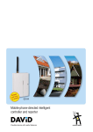
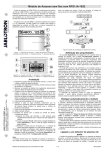
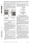
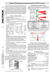
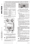
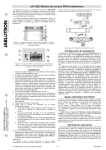
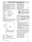
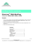
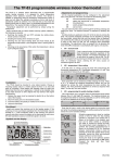
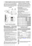
The JA-154E Wireless access module with LCD, RFID and keypad
The access module is a component of the JABLOTRON 100 system.
Its modular architecture enables users to create a combination whose
size of installation perfectly meets their needs. The device should be
installed by a trained technician with a valid certificate issued by an
authorised distributor.
2
1
ABCD...123
!
C lick
The wireless access module comprises first control segment (1),
an LCD display (4), the keypad and RFID chip card / tag reader (5).
The JA-192E segments can be used to extend the JA-154E unit by the
required number of segments (the max. allowed amount is 20 on one
unit). The tilting keypad cover (7) can be removed if the user prefers
permanent access. It also works as an RFID card / tag reader.
3
Click! 4
Figure 3: Insertion of a label into a control segment
Setting the properties
Figure 2: 8 – connector for control
segments; 9 – production code;
10 – terminals; 11 – mini USB
connector; 12 – batteries;
13 – tamper contact
Figure 1: 1 – control segment; 2 – segment buttons; 3 – backlit activation
button; 4 – LCD; 5 – access module with RFID reader; 6 – tabs for module
opening; 7 – cover screws
Installation
1. Press the four tabs (6) on the sides (see figure 1) one by one and
release the module from the plastic base.
2. When installing more control segments, first remove the socket cover on
the 1st segment.
3. Remove the transparent plastic cover from the segments (by levering
on both sides of the segment near the buttons).
JABLOTRON ALARMS a.s.
Pod Skalkou 4567/33 | 46601 | Jablonec n. Nisou
Czech Republic | www.jablotron.com
4. Always connect the segment wires to the connector of the previous
segment and click them into each other (we recommend coiling the wires
by turning the segment by 360° - this will prevent any possible damage to
the wires between the plastic parts). Use this method to install all the
required segments. Finally push the socket cover in.
5. Insert four 1.5 V alkaline AA batteries into the module.
6. Attach the base onto the selected place together with the segments
using screws. If multiple control segments are required attach them onto
the wall using screws as well (use the number of screws required).
7. Insert the module into the base.
8. Proceed according to the control panel installation manual. Basic
procedure:
a. There must be a JA-110R radio module installed in the control
panel with a reliable communication range to the access module.
b. When batteries are inserted, the yellow backlit activation button (3)
starts to light permanently which indicates that the module has not
been enrolled to the system yet.
c. Go to the F-Link software, select the required position in the
Devices window and launch enrollment mode by clicking on the
Enroll option.
d. Press the backlit activation button (3) – the module is thus enrolled
and the yellow LED indicator goes off (this can take a few sec). An
enrollment signal can also be sent by inserting the batteries.
9. When you have completed installation, insert descriptive labels behind
the segment transparent covers and close them, see figure 3. Label
printing is a part of the F-Link software (Devices window, at the module
position – Internal settings).
Notes:
The module can also be enrolled to the system by entering its
production code (9) in the F-Link software or using a bar code scanner.
All numbers stated under the bar code shall be entered (1400-00-00000001).
To comply with the EN 50131-3 norm it is necessary to fix the cover
tabs (6) by the screws from the accessories. In figure no 1 the cover
tabs are displayed and marked by the arrows.
The JA-154E wireless access module with LCD, RFID and keypad
Go to the Devices window in the F-Link software. When you are at the
module position, use the Internal settings option. The particular unit is
displayed and it is possible to set its properties. Internal settings is
separated into 2 basic tabs: Segments and Settings.
It is possible to set the required functions for individual segments (control
of sections, section status signalling, alarm triggering, PG output control, PG
output status signalling, etc.).
Common segment – settings and function description
A common segment (up to 2 of them allowed on one module unit)
simulates the simultaneous pressing of several segments which are placed
on this module and which control sections. In the F-Link SW – go to the
Devices tab at the keypad position, Segments tab and select the specific
segment function called Common segment A (B). Then in the new tab
Common segment, select the segments which will be operated en bloc.
Note: A module has to be equipped with a minimum of 3 segments
otherwise this function can not be used.
The selected sections will all be set / unset after pressing a button on the
common segment.
If the states of the segments which are operated by the common segment
are mixed, then only the segments that need changing will be set / unset.
If partial setting is enabled for some segments, then the common segment
respects this: 1st press = partially setting, 2nd press = full setting. It is not
suitable to combine a common segment with a common section.
The indication of the common segment is: all segments unset = green,
some set (partially set) = yellow, all sections fully set = red.
In the Settings tab you can set all other module functions like acoustic
signalling, backlight intensity, RFID reader mode, optical and acoustic
indication, LCD display settings, etc. Details related to settings can be found
in the installation manual of the control panel and of course in the tooltips
displayed by the F-Link software.
Battery power save mode
The module saves its energy by shutting down the optical indication of
system status, the backlit of the LCD display and the RFID reader after 8 sec
when the button, segment or keypad cover have been pressed. The module
still keeps communication with the control panel and it can signal for
example: an entrance delay. Complete waking up is done when you press
the cover of the module, or by pressing of any button.
Alternative power
The module can be powered from an external 12 V DC power supply
via the PWR and GND terminals. The DE 06-12 power supply can be
used. It has the advantage of hidden installation. It permanently
communicates with the control panel and it indicates the system status
according to the Devices / Internal settings. Leave the batteries inside
the module during alternative powering. When the mains power is cut
off, the module will work from the batteries. Inserted batteries are not
charged by the external power supply.
Connection of an external door detector
The module has an input terminal for external door detector
connection. The input (IN) reacts to disconnection from the common
ground. The reaction of this input is programmable by the F-Link SW.
The input has a status reaction.
1/2
MLU56211
The JA-154E Wireless access module with LCD, RFID and keypad
4. Connect the miniUSB cable to the USB port on the PC. The
miniUSB cable is not in the accessories of the module, control
panel or any other device. You can use the cable from the JA-190T
card reader.
Caution: We strictly recommend connecting the USB cable straight
to the PC, connection via a USB HUB can reduce the reliability).
5. Connect the miniUSB cable to the connector on the module (11).
6. Switching to the firmware upgrading mode is indicated by the
7.
Battery replacement
The module automatically checks the status of the batteries. When Low
Batt status is reported, then the batteries should be changed within 2
weeks. Before changing the batteries, system must be firstly switched to
SERVICE mode, otherwise a tamper alarm will be triggered.
Note: For the best possible operation we strongly recommend using
only batteries supplied by Jablotron’s authorized distribution (avoid usage
of so called no-name batteries).
Unit modifications
If you need to change the segments (add or take out), release them
by levering on both sides of the segment near the buttons. Always
remove batteries and also disconnect external power supply. When you
have finished changing the amount of segments the new JA-192Es are
automatically synchronized and recognized by the system and visible in
the F-Link software highlighted by blue colour.
8.
9.
10.
11.
12.
13.
backlit activation button flashing green and very slight flashing in
yellow.
Then continue as if you are doing an upgrade via F-Link software:
&RQWURO SDQHO ĺ )LUPZDUH update ĺ FKRRVH WKH XSJUDGH ILOH
pack (it is a part of the F-Link installation pack, or it can be
independently published for downloading, file type *.fwp)
F-Link shows a window with a device listing, select the USB
(typically at the first position).
Then press OK and perform the upgrade for the selected device.
Disconnect the miniUSB cable, reinsert the batteries and
reassemble the module.
Check the settings of the module via F-Link, Devices/Internal
settings. According to the changes which have been done during
the upgrade, previous settings might stay or settings could be
erased to default. When a reset has been done you can reload the
previous settings by the Import button and restore them with no
negative influence on the new firmware.
When the FW upgrade has been done, the main menu could be
expanded. In this case the new options are set to default. Check
their settings and adjust according to user requirements.
Perform a last check and try out the functions by some tests.
Optical indication
Activation button – indicates the system status. No light – sleep mode,
green light – everything OK, green flashes – authorisation performed, red
flashes – alarm, yellow light – fault / not enrolled to the system, yellow
double flash – Service mode.
Note: The activation button doesn´t indicate module tamper activation,
even the INP input, in Service mode.
Segments – don´t indicate when Service mode is entered or when the
segment has the function None. The optical indication logic of a PG segment
can be inverted.
Module can be preset to the following 6 indication levels:
1.
2.
3.
4.
5.
6.
Indicates permanently – Wireless modules indicate permanently
only if an external power supply is connected. Without an external
power supply it indicates the same as option 2. When the mains is
restored module again indicates permanently.
Section / PG status change on keypad – the module indicates
when the section / PG status has been changed. The status change
is indicated on the specific segment. Entrance delays and alarms are
indicated by the whole module.
Section / PG status change on segment – the module indicates
when a section / PG output status has been changed. A segment
status change, an entrance delay and an alarm is indicated on a
specific segment.
Segment status change on keypad – The module indicates when
the status of a segment has been changed (setting, unsetting, PG
ON, PG OFF). The change of the status is indicated only on the
specific segment.
Entrance delays / alarms on segment – the module indicates
entrance delays and alarms on a specific segment.
Wake-up by pressing – the module optically and acoustically
indicates after the front cover has been opened and also when a
button or segment has been pressed. This setting ensures a
maximum battery lifetime.
Acoustic indication
It can be set regardless of the keypad’s optical indication and sleep
mode. The module can indicate entrance / exit delays or alarms. During
valid authorization (by user code or RFID card) acoustic indication of
exit delay is supressed. By pressing the indication button the module is
muted permanently. Entrance delays and alarms are indicated until their
times expire, but only if the activation button is not pressed.
Technical specifications
Power
4 x alkaline batteries AA (LR6) 1.5 V
Please note: Batteries are not included
Typical life time
1 - 2 year(s) according to the settings
Power input from external supply
0.5 W
Communication band
868.1 MHz, JABLOTRON protocol
Communication range
200 m (open area)
Power input from external supply
0.5 W
RFID frequency
125 kHz
Dimensions
102 x 145 x 33 mm
Weight
350 g
Classification
Grade II
According to
EN 50131-1, EN 50131-3, EN 50131-5-3
Operational environment
EN 50131-1 II. Indoor general
Operating temperature range
-10 to +40 °C
Also complies with
ETSI EN 300 330, ETSI EN 300 220
EN 50130-4, EN 55022, EN 60950-1
Can be operated according to
ERC REC 70-03
JABLOTRON ALARMS a.s. hereby declares that the JA-154E
is in compliance with the essential requirements and other
relevant provisions of Directive 1999/5/EC, 2011/65/EU. The
original of the conformity assessment can be found at
www.jablotron.com - Technical Support section
FW upgrade
1. Upgrades can only be done by a Service technician and by
F-Link software.
Note: Although this product does not contain any harmful
materials we suggest you return the product to the dealer or
directly to the producer after use. For more detailed information
visit www.jablotron.com.
2. Start F-Link (in online or offline mode) and open the appropriate
3.
installation database.
Open the module by pressing on the tabs (6), remove the batteries
and any possible external power supply.
The JA-154E wireless access module with LCD, RFID and keypad
2/2
MLU56211