1
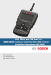
Mac TaskPlus
ET1205ANX
TM
Contents
Safety Precautions..........................................................................3
Signal Words Used..........................................................................3
Important Safety Messages............................................................3
Using the CD....................................................................................4
Installing the Scanning Suite.........................................................5
About the Tool.................................................................................5
General Scan Tool Information......................................................6
User Interface.............................................................................................. 6
Display Icons............................................................................................... 6
Using Your Scan Tool......................................................................7
Installing Internal Batteries........................................................................ 7
Powering the Tool............................................................................7
Internal Battery............................................................................................ 7
Vehicle Power.............................................................................................. 8
USB Power................................................................................................... 8
Connect the Tool.............................................................................8
Diagnostic Menu User Interface.....................................................8
Read Codes......................................................................................9
Vehicle Selection.............................................................................9
Erase Codes...................................................................................10
MIL Status......................................................................................11
I/M Monitors (Emissions)..............................................................11
Drive Cycle Monitor.......................................................................12
View Freeze Data...........................................................................12
Vehicle Information.......................................................................13
System Setup.................................................................................13
State OBD Check (Emissions).....................................................13
Long PID Names............................................................................14
View Data........................................................................................14
Entire Data List..............................................................................15
Custom Data List...........................................................................16
Record Data...................................................................................18
Review Data...................................................................................20
Recording.................................................................................................. 20
Print Data.......................................................................................21
Code Lookup..................................................................................22
O2 Monitor Test.............................................................................23
Diagnostic Monitor Test................................................................24
On-Board Systems........................................................................24
Acronyms.......................................................................................25
Component Locator......................................................................25
Modules Present............................................................................25
Updating Your Tool........................................................................26
Troubleshooting............................................................................26
PID Definitions...............................................................................27
Declaration of Conformity............................................................38
Limited Warranty...........................................................................39
2
Safety Precautions
This User’s Manual describes the features of the Tool and provides
step-by-step instructions for operating the Tool. Always refer to and follow
safety messages and test procedures provided by the manufacturer of
the vehicle and the Tool.
Read the User’s Manual completely before operating the Tool. An
undetected or uncorrected vehicle malfunction could cause a serious,
even fatal, accident. Important Safety Information in the User’s Manual is
intended to protect the user, bystanders and the user’s vehicle.
Signal Words Used
Indicates a possible hazardous situation which, if not
avoided, could result in death or serious injury to
operator or bystanders.
NOTICE
Indicates a condition which may result in lost information.
⇒⇒ Indicates a single-step procedure.
WARNING This Tool may not detect every malfunction. Do not take
chances with brakes, steering, or other vital functions of your vehicle,
as a serious accident could result.
Important Safety Messages
• Always wear ANSI approved goggles for eye protection.
• Before testing a vehicle, make sure the transmission is in PARK
(automatic transmission) or Neutral (manual transmission) and the
parking brake is set.
• Never lay tools on the vehicle battery.
• Battery acid can burn. If contacted, rinse with water or neutralize
with a mild base such as baking soda. If you splash your eyes,
flush with water and call a physician immediately.
• Never smoke or have open flames near vehicle. Vapors from
gasoline and battery are explosive.
• Do not use the Tool if internal circuitry has been exposed to
moisture. Internal shorts could cause a fire and damage the
Vehicle or Tool.
• Always turn the ignition key OFF when connecting or
disconnecting electrical components, unless otherwise instructed.
3
• Most vehicles are equipped with air bags. If you elect to work
around air bag components or wiring, follow your vehicle
service manual cautions. You could be seriously injured or
killed by an unintended deployment.
The air bag can still open several minutes
after ignition is turned off.
• Always follow vehicle manufacturer’s warnings, cautions, and
service procedures.
Using the CD
The included CD is NOT required to operate the Tool.
Install the CD application prior to connecting the Tool to the PC.
Some of the items included on the CD are:
Manuals included with Tool
Tool update software
Print capture
A link to Adobe Acrobat Reader Installer
To be able to use the included CD the PC must meet the following
minimum requirements:
Microsoft Windows, XP, Vista, and 7
CD ROM Drive
Adobe Acrobat Reader
Screen resolution of 800 x 600
⇒⇒ If screen resolution is 800 x 600, in Display Properties, Settings
Tab, set Font Size to Small Fonts.
99 Use Scanning Suite to determine if any updates are available
for your tool by clicking Check for Update button.
99 Check for updates to Use Scanning Suite by clicking on the
Check For Scanning Suite Update button. This should be
done prior to checking for Tool Updates.
99 You can also configure the Scanning Suite Frequency (SS
Frequency) to automatically check every xx minutes. The
default frequency is 7 days
4
Installing the Scanning Suite
1. Close all programs on the computer.
2. Place the CD in the CD drive. If the CD does not start
automatically:
a. Select the Start button.
b. Select Run.
c. Enter “X:\Setup.exe” in dialogue box on computer. (“X” is the
CD-ROM drive letter on the computer.)
d. Select Okay.
Enter
Run
Start
3. Follow screen prompts on the computer to install the applications.
About the Tool
The Tool allows you to retrieve and erase/reset diagnostic data from
the vehicle control module. The diagnostic data can be used to help
determine the cause of a vehicle malfunction.
Use the Tool to perform the following functions:
Codes/Data
Erase/Reset
Retrieve
Confirmed Codes
Erase
Pending Codes
Erase
Permanent Codes
--
View Data
--
MIL Status
--
I/M Monitors
Reset
Freeze Data
Erase
--
State OBD Check
Erase
Drive Cycle Monitor
Reset
O2 Monitor Test
Erase
Vehicle Information
5
Diagnostic Monitor Test
Erase
--
On-Board Systems
General Scan Tool Information
User Interface
The Tool is designed for easy use. All menus and lists operate the
same way.
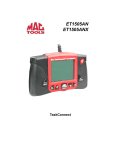
DLC INTERCONNECT CABLE
LCD Display
ON/OFF Key
BACK Key
ENTER Key
RIGHT Arrow Key
LEFT Arrow Key
UP Arrow Key
DOWN Arrow Key
DOWN UP arrow keys allow movement through lists and
menus.
t LEFT or u RIGHT arrow keys move between answers and
Recorded Data Frames. They will also page up and page down
for faster movement through lists and menus.
ENTER key selects item.
BACK key returns to previous screen.
ON/OFF key turns scan tool on or off when powered by
batteries.
Display Icons
i
h
√
gR
Shows additional information is available by scrolling down.
Shows additional information is available by scrolling up.
Shows if the internal batteries need replacing or are not
installed.
Shows selected items in a data list, or data is available for
items on the Review Data and Print Data Menu.
Shows graphical viewing of data items is available in View
Data and Record Data.
6
Using Your Scan Tool
Installing Internal Batteries
The Tool requires 4-AAA alkaline batteries when operating Tool
without vehicle power, otherwise tool is powered by vehicle battery.
When internal batteries need replacing, the low-battery icon (
displays.
)
1. Place display face down on a non-abrasive surface.
2. Remove battery cover by turning screw counterclockwise and
sliding cover off.
3. Remove batteries and properly discard.
4. Install 4 new AAA alkaline batteries.
5. Reinstall battery cover by sliding on and turning screw
clockwise.
NOTICE
Do not overtighten screw.
Powering the Tool
Internal Battery
Battery power is not required to use tool.
The ON/OFF
key on the Tool turns tool on and off. Press and hold
the ON/OFF
key for at least 1 second to turn on the Tool. The Tool
will automatically turn OFF after a user-selectable period of inactivity
when powered from the internal batteries. When powered from the
internal batteries, the Tool turns off the backlighting for the display
if no key presses are made during a 1-minute period. If a key is
pressed prior to the Tool powering off, the backlighting for the display
will turn back on.
The Tool must be attached to the vehicle to perform diagnostic
functions. The Tool disables the diagnostic functions when powered
from the internal batteries. Each time the Tool is powered up, voltage
of the internal battery is checked.
If voltage is low, the Low Battery Symbol (
) displays on screen.
Replace the battery using instructions provided in Battery
Replacement.
7
NOTICE
If the Tool will not be used for an extended period of
time, remove the batteries to prevent battery leakage
from damaging the battery compartment.
Vehicle Power
When the Tool is connected to the vehicle DLC, the Tool is powered
by the vehicle and will automatically turn on once connected.
USB Power
When the Tool is connected to a Personal Computer (PC) via the
USB cable, the Tool will automatically power up.
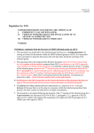
Connect the Tool
To connect the Tool to the vehicle:
1. Locate the OBD II connector under the
steering column.
If the connector is not there, a label
should be there indicating the whereabouts of the connector. For more information on OBD II connectors, go to http://
www.obdclearinghouse.com/oemdb.
2. If necessary, remove the cover from the vehicle
connector.
3. Turn the ignition switch to the ON position. Do not start the
engine.
4. Plug the OBD II connector attached to the Tool into the vehicle
connector.
The Tool automatically reads codes and I/M monitors and displays
the data. When done viewing data, press BACK key to return to
Diagnostic Menu.
Diagnostic Menu User
Interface
Diagnostic Menu
=========================
I/M Monitors
Read Codes
Erase Codes
MIL Status
State OBD Check
View Data
To select functions:
1. From the Diagnostic Menu,
press the UP or DOWN
arrow key until the desired
function is highlighted, then
press the
ENTER key to
8
retrieve and display the results.
2. When complete, press BACK to return to the Diagnostic
Menu selection screen.
Read Codes
When you view codes, the Tool displays Confirmed, Pending, and Permanent Codes. Confirmed Trouble Codes are reported when a component, sensor, or other part of the vehicle is indicating a malfunction
is present. The malfunction must be present for a sufficient amount of
time before the Tool will display a Confirmed Trouble Code. Confirmed
codes are indicated by the CONFIRMED icon.
Pending Codes are only reported if a problem occurs during the current
or last completed drive cycle. Pending Codes do not necessarily indicate
a faulty component or system. Pending Codes convert to Confirmed
Trouble Codes when an emissions problem persists long enough to
be considered a real problem, not an anomaly. Pending Codes are
indicated by a PENDING icon.
Permanent Codes are a special type of confirmed code. Permanent
Codes began being reported by vehicles beginning around 2010, so
they are not supported by every vehicle. While Confirmed Codes can
be erased by the tool, Permanent Codes cannot. Permanent Codes
are erased by the vehicle when the vehicle has determined the fault is
no longer present. Permanent Codes are indicated by a PERMANENT
icon.
Vehicle Selection
AutoID™ uses the VIN to determine the type of vehicle the tool is connected to. Vehicle manufacturers began programming the VIN into the
vehicle controller in 2000, but it was not an OBD II mandate until 2005.
Vehicles between 2000 and 2004 may or may not support AutoID™, but
vehicles after 2005 should support AutoID™. If the tool is on a vehicle
with a model year (MY) newer than the tool has coverage for, it will be
AutoID™ as MY OBD II/EOBD, or 2012 OBD II/EOBD.
Select AutoID™, Manual, or Prev from the Vehicle Diagnostics menu
with the up or down arrow keys.
If the vehicle is a year 2000 or newer, select AutoID™.
If the vehicle is 1999 or older, or if the vehicle is 2000 to 2004
but does not support AutoID™, select Manual.
If the previously tested vehicle listed after Prev: is desired,
select Prev:. If this is the first time the Tool has been used, the
9
space after Prev: will be blank.
Follow screen prompts to enter or provide vehicle information.
99 Allows mixing and matching of vehicle data.
99 The OBD II/EOBD selection is provided for vehicles that are
not listed. It is a good idea to always select your specific
vehicle when listed to get the most benefit from your tool.
99 If you have previously selected a vehicle it will appear as a
menu selection after Asian vehicles.
99 If you wish to select a vehicle other than the previous vehicle,
then choose between OBD II/EOBD, Domestic Vehicles,
European Vehicles, or Asian Vehicles and continue making
selections until the vehicle selection is complete.
Erase Codes
The Erase Codes function performs the following:
Erases codes (both Confirmed Trouble Codes and Pending
codes)
May erase Freeze Data, O2 Monitor Test, and Diagnostic
Monitor Test results depending on the vehicle.
Sets I/M Monitors to not ready.
NOTICE
Perform Erase Codes function only after systems have
been checked completely and DTCs have been written
down.
To erase codes from the vehicle computer:
1. Set the ignition to Key On and Engine Off (KOEO). Do NOT start
the vehicle. The engine should not be running.
2. Select Erase Codes from Diagnostic Menu and press
ENTER.
3. When the confirmation message appears on the display, choose
one of the following options.
• To proceed with the operation: Press
ENTER for YES.
• To cancel the operation and return to the Diagnostic Menu:
Press BACK for NO.
The Tool will automatically perform the Read Codes function after
erasing codes. The Tool will then indicate the number of codes
remaining. If after erasing codes a DTC returns, the problem has not
10
been fixed or other faults are present.
NOTICE
Permanent DTCs can not be erased with the Erase
Codes function.
MIL Status
NOTICE
MIL (Malfunction Indicator Lamp) Status indicates if the
vehicle computer is telling the MIL to illuminate when the
engine is running. Since this tool only supports powertrain
systems, the MIL is also the Check Engine Light.
• MIL ON indicates that the MIL should be ON.
• MIL OFF indicates that the MIL should be OFF.
I/M Monitors (Emissions)
Inspection / Maintenance monitors provide a snapshot of the emission
system operations by indicating that the I/M Monitors are Ready or
Not Ready. For an I/M Monitor to be Ready, the vehicle must have
completed a drive cycle (been driven long enough under proper conditions to have completed a drive cycle). A monitor must be listed as
Ready to pass an emissions test. If an I/M Monitor is Not Ready, it is
because a drive cycle has not completed.
The Tool will indicate Ready (ok), Not Ready (inc), or Not Applicable
(n/a) for each I/M Monitor. The Tool supports the following I/M Monitors:
Monitors
Expanded Name
Misfire Monitor
Misfire Monitor
Fuel System Mon
Fuel System Monitor
Comp Component
Comprehensive Components Monitor
Catalyst Mon
Catalyst Monitor
Htd Catalyst
Heated Catalyst Monitor
Evap System Mon
Evaporative System Monitor
Sec Air System
Secondary Air System Monitor
A/C Refrig Mon
Air Conditioning Refrigerant Monitor
Oxygen Sens Mon
Oxygen Sensor Monitor
Oxygen Sens Htr
Oxygen Sensor Heater Monitor
EGR/VVT Sys Mon
Exhaust Gas Recirculation or Variable Valve Timing
NMHC Cat Mon
Non-Methane Hydrocarbon Catalyst
NOx Treat Mon
Nitrogen Oxide Treatment
11
Monitors
Expanded Name
Boost Press Mon
Boost Pressure
Exhst Gas Sensr
Exhaust Gas Sensor
PM Filter Mon
Particulate Matter Filter
This is a complete list of I/M Monitors supported by the Tool. The number of monitors read by the Tool from your vehicle may vary. A diesel
vehicle, for example, does not have an oxygen sensor monitor. As a
result, there is no oxygen sensor monitor status for a diesel vehicle.
Two types of I/M Monitors tests are:
Since DTCs Cleared - shows status of the monitors since the
DTCs were last erased.
This Drive Cycle - shows status of monitors since the start
of the current drive cycle. Refer to the vehicle service manual
for more detailed information on emission-related monitors
and their status.
Some vehicles do not support This Drive Cycle. If vehicle supports
both types of monitors select Since DTCs Cleared or This Drive
Cycle as desired.
Drive Cycle Monitor
The Drive Cycle Monitor function is very similar to the I/M Monitors
though the Drive Cycle Monitor is used to view REAL TIME operations
of the emissions system on OBD II vehicles.
Drive Cycle Monitor continuously updates as the vehicle
reports operations of the emission system.
Refer to the vehicle service manual for how to perform a
drive cycle on your specific vehicle.
Drive Cycle Monitor will only show the monitors that are
inc (incomplete). When all monitors are complete the Tool
will display a message.
See I/M Monitors for more information.
View Freeze Data
View Freeze Data displays a snapshot of operating conditions at the
time the DTC was created. See PID Definitions for more information.
12
Vehicle Information
The Vehicle Information function allows the Tool to request the vehicle’s VIN number, calibration ID(s) which identifies the software version in the vehicle control module(s), calibration verification numbers
(CVN(s)), and In-use Performance Tracking (IPT).
Vehicle Information function applies to model year 2000 and newer
OBD II compliant vehicles.
Vehicle Information function is not supported by all
NOTICE The
vehicles. Also, not every vehicle supports every piece of
information (for example, CVN, IPT, VIN).
System Setup
System Setup allows:
Measurement units to be changed.
Display contrast to be changed.
Auto-Power off time to be changed.
Print Header to be turned ON or OFF
Long PID Names to be turned On or OFF.
Tool information to be viewed.
Display to be checked.
Operation of the keypad to be checked.
Memory of the tool to be checked.
Tool to be updated.
Language to be changed.
State OBD Check (Emissions)
The State OBD Check (Emissions) function is used to display a basic
status of the vehicle OBD system.
The State OBD Check function has the following areas:
MIL Status ON or OFF
Number of Codes Found
Number of Monitors OK
Number of Monitors Inc
Number of Monitors N/A
99 State OBD Check should be done with the Key On Engine
Running (KOER) due to showing MIL Status.
99 The number of codes found are Confirmed DTCs and not
Pending or Permanent DTCs.
13
99 The number of monitors that are either OK, INC or NA are
only since DTCs Cleared and not This Drive Cycle.
99 Refer to Read Codes and I/M Monitors for more detailed
information about the results.
Long PID Names
Long PID Names allows the user to enable/disable the tool scrolling
the complete PID name on the bottom line of the display while viewing
Live Data or viewing Freeze Data.
From the System Setup
menu, use the ▲UP or
▼DOWN arrow keys
until Long PID Names
is highlighted, then
press
ENTER.
System Setup
=====================
Adjust Contrast
Auto-Power Off
Quick Test
Print Header
Language Setup
Long
PID Names
Language
Setup
Select ON or OFF as
desired using the ▲UP
or ▼DOWN arrow keys,
then press
ENTER to
s a v e o r BACK to
return to System Setup.
View Data
The View Data function allows real time viewing of the vehicle’s computer module Parameter Identification Data (PID). As the computer
monitors the vehicle, information is simultaneously transmitted to the
Tool.
View Data allows the following items to be viewed on the Tool:
Sensor data
Operation of switches
Operation of solenoids
Operation of relays
View Data can be shown as:
Entire Data List
Custom Data List
14
Apart from the Read Codes, View Data is the most useful diagnostic
function for isolating the cause of a vehicle operation problem.
From the Diagnostic Menu:
1. Select View Data. Use the
UP or DOWN arrow
key until View Data is
highlighted. Press
ENTER.
2. Observe while Tool validates PID MAP.
Diagnostic Menu
=========================
I/M Monitors
Read Codes
Erase Codes
MIL Status
State OBD Check
View Data
Validating PIDs
======================
PID
X/Y
es
Please Wait
PID MAP validation is the tool asking the vehicle which PIDs are
supported. See PID Definitions for a complete list of PIDs supported
by the tool.
Multiple PIDs may be sent if vehicle is equipped with more than one
computer module (for example a powertrain control module [PCM]
and a transmission control module [TCM]. The Tool identifies them
by their identification names (ID) assigned by manufacturer (i.e. $10
or $1A). See PID Definitions for more information.
If one or more control modules stop responding, the Tool displays a
message:
If continuing , dashes will replace data in right hand column.
If NO is selected, the Tool will attempt to re-establish
communication with that module.
Entire Data List
Selecting Entire Data List from the Select Data to View menu will
show all supported PID data for the vehicle being tested.
15
From the Select Data to View menu:
1. Select Entire Data List.
Use the UP or
DOWN arrow key until
Entire Data List is
highlighted. Press
ENTER.
2. View PIDs on Tool. Use
the UP or DOWN
arrow key. See PID
Definitions for more
information.
3. If the "gR" icon displays
while a PID is selected,
press
ENTER to view
graph.
4. Press BACK to return
to PID screen.
5. Press BACK again
to Select Data to View
menu.
6. Press BACK again
to return to Diagnostic
Menu.
Select Data to View
=========================
Entire Data List
Custom Data List
Long PID Names
English / Metric
"
A/C PRESS (psi) 15.5
A/C PRESS (V)
3.00
A/F RATIO
14:1
BARO PRESS (”Hg)29.9
ABSLT TPS
ENGINE (RPM)
CALC LOAD (%)
MAF (LB / M)
12.2
2352
83.1
0.57
Custom Data List
Selecting Custom Data List from the Select Data to View menu
allows certain PIDs from the Entire Data List such as those
PIDs that apply to a specific driveability symptom or system to be
selected.
From the Select Data to View menu:
1. Select Custom Data List.
Use the DOWN or
DOWN arrow key until
Custom Data List is
highlighted. Press
ENTER.
Select Data to View
=========================
Entire Data List
Custom Data List
Long PID Names
English / Metric
16
2. A Custom Setup will be
shown. Select whether to
view instructions or not.
Use the t LEFT or u
RIGHT arrow key as
desired. Press
ENTER.
Custom Setup
======================
Do you want to view
instructions for
creatinges
a custom
data list?
YES
3. Select PIDs to View. Use
the UP or DOWN
arrow key to move up and
down the list. The u
RIGHT arrow selects or
deselects data parameter.
All selected data is marked
with a () symbol. The t
LEFT arrow deselects all
marked data parameters.
The
ENTER key starts
recording data or displaying selected data parameters.
If Long PID Names is
enabled, the complete PID
name will scroll along the
bottom line of the screen
beneath a solid line.
Selected PIDs are kept
until you exit View Data
and return to the Diagnostic Menu.
4. View PIDs on Tool. Use
UP or DOWN arrow
key to select PIDs. See
PID Definitions for more
information.
17
NO
Select Custom List
==========================
✓ MIL ($10)
MIL ($18)
TPS ($10)
✓ TPS ($18)
ENGINES ($10)
✓ ENGINES ($18)
MIL STATUS
ABSLT TPS (%)
100
ABSLT TPS (%)
0
ENG SPEED (RPM)
0
ENG SPEED(RPM)
0
BARO PRESS ("HG) 30.7
Throttle Position
"
A/C PRESS (psi) 15.5
A/C PRESS (V)
3.00
A/F RATIO
14:1
BARO PRESS (”Hg)29.9
ABSLT TPS
ENGINE (RPM)
CALC LOAD (%)
MAF (LB / M)
12.2
2352
83.1
0.57
If the "gR" icon displays
while a PID is selected,
press
ENTER to view
graph.
ABS TPS (%)
59%
100+
0 +
FRAME:
3 TM:
7.1
5. Press BACK to return to PID screen.
6. Press BACK again to Select Data to View menu.
7. Press BACK again to return to Diagnostic Menu.
Record Data
The Record Data function records PIDs while vehicle is
parked or being driven
The Record Data function is mainly used for diagnosing
intermittent driveability problems that cannot be isolated by
any other method.
The recording time varies. A recording consists of frames of
data prior to the trigger and several frames after the trigger.
Two people must be in the vehicle when driving, one to drive and the other to operate the
Tool.
From the Diagnostic Menu:
1. Select Record Data. Use
the UP or DOWN
arrow key until Record
Data is highlighted. Press
ENTER.
Diagnostic Menu
==========================
View Data
Record Data
View Freeze Data
Drive Cycle Monitor
O2 Monitor Tests
Diag Monitor Tests
2. Follow instructions on the display.
The Tool can maintain only one recording. Make sure to
thoroughly review old recording before erasing.
18
If a recording currently
exists in memory, a
message prompting to
erase data is displayed.
Record Data
======================
Previous recording in
memory. Do you want
to erase it and make
es
a new
one?
NO
YES
Recording
======================
Collecting pretrigger
data
s
Press ENTER
to
trigger recording
Tool validates list
of global PIDs from
vehicle.
Validating PIDs
======================
PID
X/Y
es
Please Wait
3. Refer to View Data to setup Custom List or View Entire List.
4. Press
ENTER to start recording.
Data continues to be
saved until either the
Recording
record memory is full or
======================
the operator presses
Collecting data for
ENTER.
frame
s #375
Tool recording times vary.
A recording consists
Press ENTER
to end
of frames of data prior
recording
to trigger and several
frames after trigger.
19
5. After recording, the Tool
will display a prompt to
Playback Data.
6. Select NO to return to Diagnostic Menu, or select YES
to display recorded data.
7. Refer to Recording for
instructions on how to
Playback Data.
Record Data
======================
Playback data?
es
YES
NO
Review Data
The Review Data function allows the user to view the
information from the previous vehicle tested.
The Tool does not require power from the vehicle to use the
Review Data function.
The Review Data menu shows a checkmark next to the
item(s) having data.
If there isn't a
checkmark next to the
item, then this item can't
be selected until the
appropriate function is
run from the Diagnostic
Menu.
Only 1 function,
Recording, requires
detailed instructions.
Review Data
===========================
✓ I/M Monitors
DTCs (Codes)
✓ State OBD Check
✓ Recording es
View Freeze Data
✓ O2 Monitor Tests
Recording
The Recording function is used to play back a recording.
This function is very similar to View Data. Unlike View Data, Recording is a viewing of previously recorded PIDs.
20
The Recording has frame number and timestamp (in seconds).
MIL STATUS
ON
ABSLT TPS(%)
100
Negative frames and
ENGINE SPEED(RPM) 688
timestamps indicate data
CALC LOAD(%)
0
MAP ("HG)
30.7
recorded before trigger
event.
FRAME:0 TM
0.0
Throttle Position
Positive frames and timestamps indicate data recorded after the trigger
event.
Use UP or DOWN arrow keys to view recorded PID data
of each frame.
Use t LEFT or u RIGHT arrow keys to scroll back and forth
through frames.
See PID Definitions for more information.
If graphing is available for selected PID, the "gR" icon located on
the side of the screen will show.
1. Press
ENTER to view
ABS TPS (%)
59%
graph.
2. Press
ENTER again to
return to Recording.
100+
• The triangle below the
graph indicates the
0 +
FRAME: 3 TM:
7.1
position of the frame
in the graph.
3. Use the t LEFT or u RIGHT arrow keys to scroll back and forth
through the graph.
Different vehicles communicate at different speeds and support a different number of PIDs. Therefore, the maximum number of frames that
can be recorded varies.
Print Data
The Print Data function allows the printing of diagnostic information stored in the Tool.
Internal battery power can be used to print data.
21
Use the Print Header function to turn On/Off printing vehicle
information prior to printing data.
Make sure you have previously installed the PC software following the instructions in Installing Scanning Suite.
Launch Scanning Suite and then start printing application.
Follow all instructions on the PC.
NOTICE
On the Print Data menu, Print All prints all data collected
by the Tool.
When printing a Recording, Start Frame and End Frame need to be
defined.
The Print Data menu shows a
check mark next to the items
having data. If there isn't a checkmark next to the item, this item
can't be selected until the appropriate function is run from the
Diagnostic Menu.
Print Data
==========================
Print All
✓ I/M Monitors
✓ DTCs (Codes)
State OBD Check
Recording
View Fre eze Data
Code Lookup
Code Lookup is used to look up definitions of DTCs stored in the Tool.
The Tool does not require power from the vehicle to perform this
function. In order for the Tool to show correct DTC definition, Vehicle
Selection is required.
NOTICE
Selecting a vehicle in Code Lookup does not change
the currently selected vehicle chosen in Read Codes.
The Code Lookup vehicle selection is only temporary. It
allows you to look up a DTC definition for a vehicle other
than the vehicle selected during Read Codes.
22
Entering codes:
Code Lookup
======================
PP 0000
Enter desired code
using keys
Press ENTER
when
done
All characters must be entered.
Only one character can be
changed at a time.
Use t LEFT or u RIGHT
arrow keys to scroll to desired digit.
Use UP and DOWN
arrow keys to change selected digit.
Press
ENTER.
Some vehicles may have an additional screen asking in which system
to look for a code. If definition could not be found, the Tool displays No
DTC Definition Found. See Service Manual.
O2 Monitor Test
OBD II regulations require applicable vehicles monitor and test oxygen
(O2) sensors to determine problems related to fuel and emissions. The
O2 Monitor Test allows retrieval of completed O2 sensors monitor
test results.
The O2 Monitor Test is not an on-demand test. O2 sensors
are not tested when selected via the menu. O2 sensors are
tested when engine operating conditions are within specified
limits.
If the vehicle communicates using a controller area network
(CAN), O2 Monitor tests are not supported by the vehicle. A
message is displayed. See Diagnostic Monitor Test to see
O2 monitor data.
O2 sensors are located before (upstream) and after (downstream)
catalyst(s). Sensors are named (xy) for their position to both cylinder
banks and catalysts.
The O2 sensor for cylinder bank 1 has prefix 1y while O2
sensor for cylinder bank 2 has prefix 2y.
The O2 sensor upstream of catalyst (closest to engine) has
suffix x1 while O2 sensor downstream of catalyst has suffix
x2. If vehicle contains more catalysts, O2 sensor downstream
of second catalyst has suffix x3 and O2 sensor downstream
23
of next catalyst has suffix x4.
For example, O2S21 is upstream O2 sensor for cylinder bank
2.
Diagnostic Monitor Test
The Diagnostic Monitor Test function is useful after servicing or after
erasing a vehicle’s memory. Test results do not necessarily indicate a
faulty component or system. Vehicle manufacturer is responsible for
assigning test and component IDs.
Non-CAN vehicles Diagnostic Monitor Test receives test results for
emission-related powertrain components and systems that are not
continuously monitored.
On Non-CAN vehicles the Tool displays:
Test data (test ID)
Maximum value (MAX)
Test measurements (MEAS)
Minimum value (MIN)
Status (STS)
Measurements and specification values are hexadecimal
numbers (i.e., $1A, $FE, $11.)
Module (MOD)
OR
CAN vehicles Diagnostic Monitor Test receives test results for
emission-related powertrain components and systems that are and
are not continuously monitored.
On CAN vehicles the Tool displays:
Test performed. The test performed can be $## if test is not
defined. Refer to vehicle service manual for details.
Measured values and units of measure (such as volts, amps,
seconds).
Status of monitor test data.
Module ID where the monitor test data came from.
On-Board Systems
The On-Board Systems test allows the Tool to control operation of
vehicle components, tests, or systems.
Some manufacturers do not allow tools to control vehicle
24
systems. A vehicle not supporting an on-board system is
identified by a message displayed when selected.
Refer to the appropriate vehicle service manual for on-board
systems instructions.
After selecting On-Board Systems, a list of on-board
systems and components available for testing are shown on
the display.
Acronyms
The Acronyms function allows the user to view acronyms and abbreviations used by the Scan Tool.
99 Acronyms function is accessed from the Main Menu
Component Locator
The Component Locator provides a vehicle specific location of components found on the selected vehicle.
The Component Locator function can be selected from
the Main or Diagnostic menus. Since Component Locator
provides vehicle specific component location, a previous
vehicle must be stored in the Scan Tool.
Modules Present
The Modules Present function identifies the module IDs and communication type for all Global OBD II modules in the vehicle.
99 Selected from the Diagnostic Menu. Use up and down arrow
keys to Modules Present and press Enter
The types of protocols (communication types) supported by the Scan
Tool are:
ISO 9141-2 (shown on the Scan Tool as “ISO”)
SAE J1850 (shown on the Scan Tool as “VPWM or PWM”)
ISO 15765-4 (shown on the Scan Tool as “CAN”)
ISO 14230-4 (shown on the Scan Tool as “K2K” (meaning
“Keyword 2000”))
99 Since CAN vehicles use module IDs larger than 2 digits, The
Scan Tool assigns a 2-digit module ID to be used in place of
the actual CAN module ID. The module ID assigned for the
CAN module ID is used in all functions of he Scan Tool.
25
Updating Your Tool
1.
2.
3.
4.
Refer to Install Scanning Suite.
Connect USB cable to Tool and PC.
Select Program Mode on Tool from the System Setup menu.
Start Scanning Suite. Click on Tool Update Icon and follow instructions.
Troubleshooting
If a “LINK ERROR” message appears, cycle the ignition key
to the OFF position for 10 seconds, then back ON, then press
the
ENTER key. Make sure the ignition key is in the ON
n o t the ACCESSORY position.
If the MIL Status is ON and the MIL is not illuminated with the
engine running, then a problem exists in the MIL circuit.
26
PID Definitions
NOTE: Even though there are over 300 PIDs, the Tool only
displays the PIDs the vehicle supports.
Tool
Description
ABS FRP
Absolute Fuel Rail Pressure
ABS LOAD
Absolute Load Value
ABS TPS B, C
Throttle Position B, C
ABSLT TPS
Absolute Throttle Position
ACC POS D
Accelerator Pedal D, E, F
ACC POS REL
Relative Accelerator Pedal Position
AECD1_TIME1,
TIME 2
Total Run Time with EI-AECD #1 Timer 1 Active, #2
Timer Active
AECD10_TIME1,
TIME 2
Total Run Time with EI-AECD #10 Timer 1 Active, #2
Timer Active
AECD11_TIME1,
TIME 2
Total Run Time with EI-AECD #11 Timer 1 active, #2
Timer Active
AECD12_TIME1,
TIME 2
Total Run Time with EI-AECD #12 Timer 1 active, #2
Timer Active
AECD13_TIME1,
TIME 2
Total Run Time with EI-AECD #13 Timer 1 active, #2
Timer Active
AECD14_TIME1,
TIME 2
Total Run Time with EI-AECD #14 Timer 1 active, #2
Timer Active
AECD15_TIME1,
TIME 2
Total Run Time with EI-AECD #15 Timer 1 active, #2
Timer Active
AECD16_TIME1,
TIME 2
Total Run Time with EI-AECD #16 Timer 1 active, #2
Timer Active
AECD17_TIME1,
TIME 2
Total Run Time with EI-AECD #17 Timer 1 active, #2
Timer Active
27
Tool
Description
AECD18_TIME1,
TIME 2
Total Run Time with EI-AECD #18 Timer 1 active, #2
Timer Active
AECD19_TIME1,
TIME 2
Total Run Time with EI-AECD #19 Timer 1 active, #2
Timer Active
AECD2_TIME1,
TIME 2
Total Run Time with EI-AECD #2 Timer 1 Active, #2
Timer Active
AECD20_TIME1,
TIME 2
Total Run Time with EI-AECD #20 Timer 1 active, #2
Timer Active
AECD3_TIME1,
TIME 2
Total Run Time with EI-AECD #3 Timer 1 Active, #2
Timer Active
AECD4_TIME1,
TIME 2
Total Run Time with EI-AECD #4 Timer 1 Active, #2
Timer Active
AECD5_TIME1,
TIME 2
Total Run Time with EI-AECD #5 Timer 1 Active, #2
Timer Active
AECD6_TIME1,
TIME 2
Total Run Time with EI-AECD #6 Timer 1 Active, #2
Timer Active
AECD7_TIME1,
TIME 2
Total Run Time with EI-AECD #7 Timer 1 Active, #2
Timer Active
AECD8_TIME1,
TIME 2
Total Run Time with EI-AECD #8 Timer 1 Active, #2
Timer Active
AECD9_TIME1,
TIME 2
Total Run Time with EI-AECD #9 Timer 1 Active, #2
Timer Active
ALCOHOL
Alcohol Fuel Percent
BARO PRS
Barometric Pressure
28
Tool
Description
BAT_PWR
Hybrid Battery Pack Remaining Life
BP_A_ACT,
B_ACT
Boost Pressure Sensor A, Sensor B
BP_A_CMD,
B_CMD
Commanded Boost Pressure A, Pressure B
BP_A_STAT,
B_STAT
Boost Pressure A Control Status, B Control Status
CACT 11, 12
Charge Air Cooler Temperature Bank 1 Sensor 1
supported, Sensor 2 supported
CACT 21,22
Charge Air Cooler Temperature Bank 2 Sensor 1
supported, Sensor 2 supported
CALC LOAD
Calculated Engine Load
CAT TEMP11,
TEMP12
Cataltic Converter Temp Bank1, Temp Bank 3
CAT TEMP21,
TEMP22
Cataltic Converter Temp Bank2, Temp Bank 4
CLR DIST
Distance since erase
CLR TIME
Minutes Run since Erase
CLR TRPS
Warmups Since Erase
CMD EQ RAT
Commanded Equivalence Ratio
COOLANT
Engine Coolant Temp
DPF_REG_AVGD
Average Distance Between DPF Regen
DPF_REG_AVGT
Average Time Between DPF Regen
DPF_REG_STAT
Diesel Particulate Filter (DPF) Regen Status
29
Tool
Description
DPF_REG_TYP
Diesel Particulate Filter (DPF) Regen Type
DPF_REGEN_
PCT
Normalized Trigger for DPF Regen
DPF1_DP,
DPF2_DP
Diesel Particulate Filter (DPF) Bank 1 Delta Pressure
Ban,k 2 Delta Pressure
DPF1_INP,
DPF2_INP
Diesel Particulate Filter (DPF) Bank 1 Inlet Pressure,
Bank 2 Inlet Pressure
DPF1_INT,
DPF2_INT
DPF Bank 1 Inlet Temperature Sensor, Bank 2 Inlet
Temperature Sensor
DPF1_OUTP,
DPF2_OUTP
Diesel Particulate Filter (DPF) Bank 1 Outlet Pressure,
Bank 2 Outlet Pressure
DPF1_OUTT,
DPF2_OUTT
DPF Bank 1 Outlet Temperature Sensor, Bank 2 Outlet
Temperature Sensor
ECT 1, 2
Engine Coolant Temperature 1, Temperature 2
EGR CMD
Comanded EGR
EGR ERR
Exhaust Gas Recirculation Error
EGR_A_ACT,
B_ACT
Actual EGR A Duty Cycle/Position, B Duty Cycle/
Position
EGR_A_CMD,
B_CMD
Commanded EGR A Duty Cycle/Position, B Duty
Cycle/Position
EGR_A_ERR,
B_ERR
EGR A Error, B Error
EGRT 11, 21
Exhaust Gas Recirculation Temperature Bank 1
Sensor 1, Bank 2 Sensor 1
EGRT 12, 22
Exhaust Gas Recirculation Temperature Bank 1
Sensor 2, Bank 2 Sensor 2
EGT 11, 21
Exhaust Gas Temperature (EGT) Bank 1 Sensor 1,
Bank 2 Sensor 1
EGT 12, 22
Exhaust Gas Temperature (EGT) Bank 1 Sensor 2,
Bank 2 Sensor 2
30
Tool
Description
EGT 13, 23
Exhaust Gas Temperature (EGT) Bank 1 Sensor 3,
Bank 2 Sensor 3
EGT 14, 24
Exhaust Gas Temperature (EGT) Bank 1 Sensor 4,
Bank 2 Sensor 4
EMIS_SUP
Emission requirements to which vehicle is designed
ENG RUN
Time Since Engine Start
ENG SPEED
Engine RPM
EOT
Engine Oil Temperature
EP_1, 2
Exhaust Pressure Sensor Bank 1, Bank 2
EQ RATIO
Equivalence Ratio
EVAP PURGE
Commanded EVAP Purge
EVAP VP
EVAP Vapor Pressure
EVAP VPA
Absolute EVAP Vapor Pressure
FRP_A, B
Fuel Rail Pressure A, B
FRP_A_CMD,
B_CMD
Commanded Fuel Rail Pressure A, B
FRT_A, B
Fuel Rail Temperature A, B
FUEL LEVEL
Fuel Level Input
FUEL PRES
Fuel Rail Pressure
FUEL SYS 1, 2
Fuel System 1 Loop Status, System 2 Loop Status
31
Tool
Description
FUEL TYPE
Fuel Type
FUEL_RATE
Engine Fuel Rate
FUEL_TIMING
Fueling Injection Timing
GPL_STAT
Glow Plug Lamp Status
IAF_A_CMD,
B_CMD
Commanded Intake Air Flow A Control, B Control
IAF_A_REL,
B_REL
Relative Intake Air Flow A Position, B Position
IAT
Intake Air Temp
IAT 11, 21
Intake Air Temperature Sensor Bank 1 Sensor 1, Bank
2 Sensor 1
IAT 12, 22
Intake Air Temperature Sensor Bank 1 Sensor 2, Bank
2 Sensor 2
IAT 13, 23
Intake Air Temperature Sensor Bank 1 Sensor 3, Bank
2 Sensor 3
ICP_A, B
Injection Control Pressure A, B
ICP_A_CMD,
B_CMD
Commanded Injection Control Pressure A, B
IDLE_TIME
Total Idle Run Time
IGN ADV
Timing Advance
LAMBDA11, 21
02 Sensor Lambda Bank 1 Sensor 1, Bank 2 Sensor 1
LAMBDA12, 22
02 Sensor Lambda Bank 1 Sensor 2, Bank 2 Sensor 2
LT FTRM1
Long Term Fuel Trim 1 or 3
32
Tool
Description
LT FTRM2
Long Term Fuel Trim 2 or 4
LT SEC FT1, 2,
3, 4
Long Term Secondary O2 Sensor Fuel Trim 1, 2, 3, 4
MAF, A, B
Mass Air Flow, A, B
MAP, A, B
Manifold Absolute Pressure, A, B
MIL DIST
MIL_DIST
MIL STATUS
Malfunction Indicator Lamp
MIL TIME
Minutes Run by MIL activated
MST
Manifold Surface Temperature
N/D_STAT
Auto Trans Neutral Drive Status
N/G_STAT
Manual Trans Neutral Gear Status
NNTE_Stat
NOx NTE control area status
NOX 11, 21
NOx Sensor Concentration Bank 1 Sensor 1, Bank 2
Sensor 1
NOX 12,22
NOx Sensor Concentration Bank 1 Sensor 2, Bank 2
Sensor 2
NOX LEVEL HI,
HI1, HI2, HI3, HI4
SCR inducement system actual state 10K history HI1
(0 - 10000 km), 10K history HI2 (10000 - 20000 km),
10K history HI3 (20000 - 30000 km), 10K history HI4
(30000 - 40000 km): NOx emission too high
NOX_ADS_
DESUL
NOx Adsorber Desulfurization Status
NOX_ADS_
REGEN
NOx Adsorber Regen Status
33
Tool
Description
NWI_TIME
Total Run Time by the Engien whicle NOx warning
mode is activated
O2S
O2 Voltage or Current indicates Bank/Sensor
O2S11_PCT,
O2S21_PCT
02 Sensor Concentration Bank 1 Sensor 1, Bank 2
Sensor 1
O2S12_PCT,
O2S22_PCT
02 Sensor Concentration Bank 1 Sensor 2, Bank 2
Sensor 2
OBD2 STAT
OBD Status
OUT TEMP
Ambient Air Temp
PM 11, PM 21
PM Sensor Mass Concentration Bank 1 Sensor 1,
Bank 2 Sensor 1
PNTE_Stat
PM NTE control area status
PTO STATUS
PTO Status
PTO_STAT
Power Take Off (PTO) Status
PTO_TIME
Total Run Time With PTO Active
REAG_DEMD
Average Demanded Reagent Consumption
REAG_LVL
Reagent Tank Level
REAG_RATE
Average Reagent Consumption
REL FRP
Relative Fuel Rail Pressure
REL TPS
Relative Throttle Position
RUN_TIME
Total Engine Run Time
34
Tool
Description
SCR REAG DEV,
DEV1, DEV2,
DEV3, DEV4
SCR inducement system actual state 10K history
DEV1 (0 - 10000 km), 10K history DEV2 (10000 20000 km), 10K history DEV3 (20000 - 30000 km),
10K history DEV4 (30000 - 40000 km): deviation of
reagent consumption
SCR REAG LOW,
LOW1, LOW2,
LOW3, LOW4
SCR inducement system actual state 10K history
LOW1 (0 - 10000 km), 10K history LOW2 (10000 20000 km), 10K history LOW3 (20000 - 30000 km),
10K history LOW4 (30000 - 40000 km): reagent level
too low
SCR REAG
WRONG,
WRONG1,
WRONG2,
WRONG3,
WRONG4
SCR inducement system actual state 10K history
WRONG1 (0 - 10000 km), 10K history WRONG2
(10000 - 20000 km), 10K history WRONG3 (20000
- 30000 km), 10K history WRONG4 (30000 - 40000
km): incorrect reagent
SCR SYS
ACTIVE
SCR inducement system actual state: inducement
system active
SCR_DIST_1D
Distance travelled in current 10K block (0 - 10000 km)
SCR_DIST_1N,
2N, 3N, 4N
Distance travelled while inducement system active in
current 10K block 1N (0 - 10000 km), 20K block 2N
(10 - 20000 km), 30K block 3N (20 - 30000 km), 40K
block 4N (30 - 40000 km)
SECOND AIR
Secondary Air Status
ST FTRM
Fuel Trim Bank/Sensor
ST FTRM1, 3
Short Term Fuel Trim1 or 3
ST FTRM2, 4
Short Term Fuel Trim2 or 4
ST SEC FT1, 2,
3, 4
Short Term Secondary O2 Sensor Fuel Trim 1, 2, 3, 4
TAC_A_CMD,
B_CMD
Commanded Throttle Actuator A Control, B Control
35
Tool
Description
TAC_A_REL,
B_REL
Relative Throttle A Position, B Position
TCA_CINP,
TCB_CINP
Turbocharger Compressor Inlet Pressure Sensor A,
Pressure Sensor B
TCA_CINT,
TCB_CINT
Turbocharger A Compressor Inlet Temperature,
Turbocharger B
TCA_COUT,
TCB_COUT
Turbocharger A Compressor Outlet Temperature,
Turbocharger B
TCA_RPM,
TCB_RPM
Turbocharger A RPM, B RPM
TCA_TCOUT,
TCB_TCOUT
Turbocharger A Turbine Outlet Temperature,
Turbocharger B
TCA_TINT,
TCB_TINT
Turbocharger A Turbine Inlet Temperature,
Turbocharger B
THROT CMD
Commanded Throttle Actuator Control
TP G
Absolute Throttle Position G
TQ_ACT
Actual Engine - Percent Torque
TQ_DD
Driver's Demand Engine - Percent Torque
TQ_MAX1, 2, 3,
4, 5
Engine Percent Torque At Point 1 (Idle), Point 2, 3, 4, 5
TQ_REF
Engine Reference Torque
TROUB CODE
Code causing the Freeze Frame
VEH SPEED
Vehicle Speed
VGT_A_ACT,
B_ACT
Variable Geometry Turbo A Position, Turbo B
VGT_A_CMD,
B_CMD
Commanded Variable Geometry Turbo A Position,
Turbo B
36
Tool
Description
VGT_A_STAT, B_STAT
Variable Geometry Turbo A Control Status, Turbo B
VPWR
Control Module Voltage
WG_A_ACT,
B_ACT
Wastegate A Position, B Position
WG_A_CMD,
B_CMD
Commanded Wastegate A Control, B Control
37
Declaration of Conformity:
This product is declared to be in compliance with the
European RoHS Directive 2002/95/EC which restricts
the following substances in electrical and electronic
equipment:
Substance
Maximum Concentration
Cadmium (Cd)
100 ppm
Hexavalent Chromium (CrVI)
1000 ppm
Lead (Pb)
1000 ppm
Mercury (Hg)
1000 ppm
Polybrominated Biphenyls (PBB)
1000 ppm
Polybrominated Diphenyl Ethers (PBDE)
1000 ppm
This product is declared to conform to the following standard
under the EMC directive 89/336/EEC.
EN 61326-1:2006
Disposal Information
This product should be disposed of separately from household
waste. When the product reaches its end of life, dispose of it
according to local laws and regulations.
Matthew Koran
Hardware Development Manager
SPX Corporation
Service Solutions
Brook Park, Ohio, USA
April 27, 2011
38
Limited Warranty
THIS WARRANTY IS EXPRESSLY LIMITED TO ORIGINAL RETAIL
BUYERS OF SPX ELECTRONIC DIAGNOSTIC TOOLS (“UNITS”).
SPX Units are warranted against defects in materials and workmanship for one year
(12 months) from date of delivery. This warranty does not cover any Unit that has been
abused, altered, used for a purpose other than that for which it was intended, or used in
a manner inconsistent with instructions regarding use. The sole and exclusive remedy
for any Unit found to be defective is repair or replacement, the option of SPX. In no
event shall SPX be liable for any direct, indirect, special, incidental or consequential
damages (including lost profit) whether based on warranty, contract, tort or any other
legal theory. The existence of a defect shall be determined by SPX in accordance
with procedures established by SPX. No one is authorized to make any statement or
representation altering the terms of this warranty.
DISCLAIMER
THE ABOVE WARRANTY IS IN LIEU OF ANY OTHER WARRANTY,
EXPRESSED OR IMPLIED, INCLUDING ANY WARRANTY OF
MERCHANTABILITY OR FITNESS FOR A PARTICULAR PURPOSE.
SOFTWARE
Unit software is proprietary, confidential information protected under copyright law. Users
have no right in or title to Unit software other than a limited right of use revocable by
SPX. Unit software may not be transferred or disclosed without written consent of SPX.
Unit software may not be copied except in ordinary backup procedures.
TECHNICAL SUPPORT
If you have any questions on the operation of the product, please call 1-800-MACTOOLS.
REPAIR SERVICE
•
Please contact Technical Support for troubleshooting and service options prior
to sending any unit in for repair.
•
To send a unit in for repair, go to www.Repairtrack.spx.com and follow the
online instructions. This website will also have the latest Service policies
and service cener locations. If you do not have internet access, please call
1-800-MAC-TOOLS.
© 2010 SPX
0002-002-3147