1
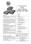
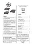
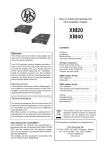
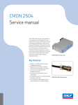
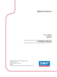
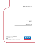
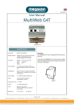
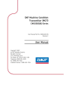
User manual SKF Multilog On-Line System IMx-B User Manual Part No. 32293200-EN Revision C WARNING! Read this manual before using this product. Failure to follow the instructions and safety precautions in this manual can result in serious injury, damage to the product, or incorrect readings. Keep this manual in a safe location for future reference. Copyright 2015 by SKF USA Inc. All rights reserved. 5271 Viewridge Court., San Diego, CA 92123-1841 USA Telephone: (858) 496-3400, Fax: (858) 496-3531 Customer Service: 1-800-523-7514 SKF USA Inc. ® SKF is a registered trademark of the SKF Group. All other trademarks are the property of their respective owners. © SKF 2015 The contents of this publication are the copyright of the publisher and may not be reproduced (even extracts) unless prior written permission is granted. Every care has been taken to ensure the accuracy of the information contained in this publication but no liability can be accepted for any loss or damage whether direct, indirect or consequential arising out of the use of the information contained herein. SKF reserves the right to alter any part of this publication without prior notice. Patents: US 4,768,380 • US 5,633,811 • US 5,679,900 • US 5,845,230 • US 5,852,351 • US 5,854,553 • US 5,854,994 • US 5,870,699 • US 5,907,491 • US 5,992,237 • US 6,006,164 • US 6,124,692 • US 6,138,078 • US 6,199,422 • US 6,202,491 • US 6,275,781 • US 6,301,514 • US 6,437,692 • US 6,489,884 • US 6,513,386 • US 6,633,822 • US 6,789,025 • US 6,792,360 • US 7,103,511 • US 7,697,492 • WO/2003/048714 Product Support – Contact Information Product Support – To request a Return Authorization, Product Calibration or a Product Support Plan, use the web page links for direct contact and support. Product Sales - For information on purchasing condition monitoring products, services or customer support, contact your local SKF sales office. General Product Information For general product information (i.e., product data sheet, accessories catalog, etc.), visit the Condition Monitoring Products page on SKF.com and select the appropriate product link. Technical Support Group Discuss/review issues of specific interest with maintenance and reliability specialists from around the world at the SKF Knowledge Centre. For technical support on issues like troubleshooting product installation, troubleshooting product performance, etc., use our technical support web page to contact one of our Technical Support Groups. Product Registration Please take a moment to register your product at www.skf.com/cm/register to receive exclusive benefits offered only to our registered customers, including receiving technical support, tracking your proof of ownership, and staying informed about upgrades and special offers. (Please visit our website for more details on these benefits.) Tell us how we’re doing! It’s important that you’re satisfied with the quality of our product user manuals. We appreciate your feedback; if you have comments or suggestions for improvement, please tell us how we’re doing! 111615jg Table of Contents Introduction 1 Important Messages .................................................. 1-1 System Overview........................................................ 1-2 IMx-B Unit ................................................................... 1-3 Installation 2 Safety and Requirements ......................................... 2-1 Mounting IMx-B Unit ................................................. 2-2 Sensor Cables ............................................................. 2-2 Cable Glands ............................................................... 2-3 Power Supply .............................................................. 2-3 Communication Cable ............................................... 2-3 Data Communication ................................................. 2-3 GPRS Router ............................................................... 2-4 Ethernet Cable ............................................................ 2-4 Unit Configuration 3 Analogue Inputs .......................................................... 3-1 Digital Inputs ............................................................... 3-3 RS485 Communication ............................................. 3-5 Relays and Dig Input Buffered Output ................... 3-6 Network Configuration .............................................. 3-8 IMx-B Time ...............................................................3-10 Router Setup for IMx-B .......................................... 3-11 Hardware Maintenance 4 Electrical Waste 5 Troubleshooting Guide 6 Problems and Symptoms ......................................... 6-1 Component Check ...................................................... 6-4 Technical Data 7 Environmental ............................................................ 7-1 Power Supply .............................................................. 7-1 SKF Multilog On-Line System IMx-B User Manual TOC - 1 Analogue Inputs ......................................................... 7-1 Digital Inputs ............................................................... 7-1 Outputs ........................................................................ 7-1 Interface ....................................................................... 7-2 Analogue Measurement............................................ 7-2 Digital Measurement ................................................. 7-2 Signal Processing ....................................................... 7-2 Data Processing ......................................................... 7-3 Miscellaneous.............................................................. 7-3 Quality Control ............................................................ 7-3 IMx-T Drawings 8 IMx-B Unit Dimensions ............................................. 8-1 Terminal List ............................................................... 8-2 Limited Warranty A Index TOC - 2 SKF Multilog On-Line System IMx-B User Manual 1 Introduction Important Messages The following messages are important information which require special care in order to have a safe and reliable IMx-B system. Important messages, instructions and information in this manual must be carefully followed. Otherwise, harm might occur to equipment and/or personnel. Important messages, instructions and information in this manual must be carefully followed. Otherwise, harm might occur to equipment and/or personnel. IMx-B unit contains circuit boards that are static sensitive. Therefore, use appropriate precautions to prevent ElectroStatic Discharge (ESD) when handling circuit boards. Make sure that IMx-B is installed in an environment within its specification. Lightning strikes, power surges and other electrical anomalies can damage IMx-B device. Important messages related to power supply: • The IMx-B is powered by 24 V DC. Do NOT apply higher voltage. • Make sure that the power is disconnected before the installation. • 24 V DC cable must be properly fixed with a cable gland to prevent the cord from strain, twist or move. See Cable Glands section as well. • High voltage power may exist in the same proximity of IMx-B. User caution to avoid contact with any voltage source. • For permanently connected IMx-B, an external all pole power switch is recommended to be installed in order to disconnect the IMx-B from the mains power grid. The switch must be labeled "IMx-B” or similar. On/Off position must be clearly marked. The switch must be located close to the IMx-B, within operator's easy reach. SKF Multilog On-Line System IMx-B User Manual 1-1 Introduction System Overview DIP switch settings must be handled with special care to prevent any damage to IMx-B unit: • Do NOT change DIP switch settings while the IMx-B unit is powered-up, as this may cause damage and void warranty. • Before powering up the IMx-B unit, make sure that DIP switch settings are properly set to match the recommendations for the connected sensors. Incorrect settings may cause permanent damage to the IMx-B unit. The power of IMx-B unit must be turned off before maintenance. System Overview IMx-B is a bogie condition monitoring system that transmits data to an office server wirelessly. Temperature and vibration sensors or other type of sensors can be placed on traction motors, gearboxes and axle boxes with wires leading in to the IMx-B. IMx-B is a part of the SKF Multilog On-line System product range. In conjunction with SKF @ptitude Observer, the IMx-B provides a complete system for early fault detection and prevention, automatic advice for correcting existing or impending conditions and advanced condition-based maintenance to improve machine reliability, availability and performance. Figure 1 - 1. System Overview, IMx-B with @ptitude Observer. The picture above illustrates how IMx-B units are linked together in a network that is connected via a GPRS and SKF @ptitude Observer Monitor. The @ptitude Observer Monitor in turn can be connected to e.g. a LAN network making it possible for several of @ptitude Observer clients to link to this network. @ptitude Observer clients can also be installed on the same computer as @ptitude Observer Monitor Service login software. Through a general interface, also known as ODBC (open database connectivity), it is possible to link @ptitude Observer Monitor login 1-2 SKF Multilog On-Line System IMx-B User Manual Introduction IMx-B Unit computer to an existing database for an existing control or processing system, if desired. It is also possible to connect different types of on-line units in the same network, for example, IMx-B together with other IMx units. IMx-B Unit Figure 1 - 2. SKF Multilog On-line System IMx-B, Outside. Figure 1 - 3. SKF Multilog On-line System IMx-B, Inside. IMx-B • Up to 16 analogue channels • Up to 8 digital sensors, where 4 of the digital input channels are configurable for standard trigger sensors (specified in Digital Inputs) and 4 channels for square pulses with trigger level 12 to 24 V SKF Multilog On-Line System IMx-B User Manual 1-3 Introduction IMx-B Unit Storage Capacity Each IMx-B unit has 8 MB flash memory used for the following: • 2 MB for firmware, configuration files, etc. • 2 MB for trend value buffer • • – About 13 000 vibration trend values can be buffered. – Speed and process data use half the space of vibration. 4 MB for spectra and time signal buffer – About 250 spectra using 1 600 lines with phase and time signal can be buffered. – If you use more lines, the number of spectrum is reduced. – If you use less lines, the number of spectrum is increased When the buffer gets full, the oldest data is thrown away. IMx-B Unique Features • Built-in GPRS Router • IP 66 stainless steel box • Meets standard requirements of EN 50155 for railway bogie mounted electronics • The unit's unique built-in hardware auto-diagnosis system continuously checks all sensors, cabling and electronics for any faults, signal interruption, short circuits or power failure. • Individual conditions for alert and danger may be set for each measurement point. • Alert and danger levels may be controlled by machine speed or load. However, it is also possible to manually bypass the alert and danger functionality. Initiating IMx-B Initiating the IMx-B is simple to carry out. 1-4 • This is done through an application @ptitude On-line Device Configurator application tool and a (portable) computer using RS232 serial interface. • The network configuration parameters, such as IP address, IMx identification number, etc. are stored in a separate configuration file first, and then transferred to the IMx-B memory. These are retained in the event of power losses, so that the IMx-B can start automatically when power returns. SKF Multilog On-Line System IMx-B User Manual 2 Installation The installation of an IMx-B must be carried out according to the instructions and advice given in this manual. Any deviation from these directions can be made only after consulting with the SKF Condition Monitoring Center Luleå. Installation errors can lead to a situation where the system does not work as intended and machinery faults go undetected. Therefore, contact the IMx-B application engineer at the slightest doubt during the installation. Note - Installation errors which require the involvement of SKF Condition Monitoring Center Luleå personnel in order to rectify the start of the system might be debited. Safety and Requirements It is important to assess and evaluate the current site for safety instructions and stipulations. During the installation work, make oneself acquainted with the valid safety stipulations for the specific machine. Different types of machines can have different safety hazards and safety instructions. In all cases, read the instructions carefully and act accordingly. IMx-B unit contains circuit boards that are static sensitive. Therefore, use appropriate precautions to prevent ElectroStatic Discharge (ESD) when handling circuit boards. The following are some of the ways to prevent ESD: • Use an ESD wrist strap when handling circuit boards • Use a grounding mat when handling circuit boards • Use correct packaging materials such as antistatic bags when transferring circuit boards Important - IMx-B unit contains circuit boards that are static sensitive. Therefore, use appropriate precautions to prevent ElectroStatic Discharge (ESD) when handling circuit boards. The ambient temperature is found in the Error! Reference source not found. section under Technical Data. SKF Multilog On-Line System IMx-B User Manual 2-1 Installation Mounting IMx-B Unit Mounting IMx-B Unit Follow these steps to mount the IMx-B unit. • First, remove all the electronic parts within the IMx-B stainless steel box. • The IMx-B stainless steel box can be attached to the bogie with four screws. The necessary holes to be made for the mounting are marked on the back of the box, in each corner. Also at this time drill the holes for the cable glands needed and mount them. • Once the holes are drilled, make sure to clean up all the metal debris within the box. • Mount the box and make sure that it is firmly attached and properly sealed. It is important not to affect IP classification of 66. • The mounting location shall not be exposed to unnecessary radiant heat or strong magnetic fields. • Now set all the electronic parts back in the IMx-B stainless steel box. Important - Remove all the electronic parts within the IMx-B stainless steel box before drilling the holes. Important - Make sure that there is no metal debris in the IMx-B stainless steel box before mounting the unit. Sensor Cables When routing a sensor cable, it is important that the cable is firmly fixed. The cable may never be allowed to vibrate or oscillate, since this effects the capacitance of the cable, and thereby the measurement result. The sensor cable may not be routed or bundled together with supply cables because it generates strong magnetic fields. Important - In general, all cables must be routed as far away as possible from the high voltage cables. If this cannot be done, care should be taken to use high quality shielded cables. To connect IMx-B to sensors, the following sensor cable type is recommended: • 2-2 2 Shielded, twisted pair 2 × 2 × 0,5 mm (FKAR-PG 2 × 2 × 0.50, DUE 4002 or corresponding) SKF Multilog On-Line System IMx-B User Manual Installation Cable Glands Cable Glands The sensor cable shields are recommended to be grounded to IMx-B unit with metallic EMC type cable glands with 360 degree shield. This is recommended for all cable leadthrough except the power supply. It is also recommended to have EMC protective hose for cable glands. Important - All cable glands must be made of material with fire protection V-1 or better. Power Supply In order to attach 24 V DC power supply, IMx-B must be installed on a grounded metal part for example a bogie frame. The attachment points must be fixed in a secure way. Important - Make sure that the power is turned off before touching the power cable. Figure 2 - 1. 24 V DC Power Supply Terminals. Refer to Power Supply in Technical Data section for power requirements. Communication Cable If the GPRS Router is bypassed, then it is recommended to use S-FTP (screened shielded twisted pair) Ethernet cable CAT5/6. The shield should be grounded with EMC cable gland. Data Communication IMx-B unit data communications are compliant with the Ethernet standard 10/100 Mbit (half- and full-duplex). IMx-B has two Ethernet ports which work like an internal network switch. SKF Multilog On-Line System IMx-B User Manual 2-3 Installation GPRS Router GPRS Router IMx-B has a built-in GPRS Router for communication from IMx-B to a server which may be located in a place away from the vehicle. Ethernet Cable The Ethernet TP cable on the IMx-B is connected at one of the standard Ethernet RJ45 connections. Both Ethernet ports have auto detection of crossover or straight through Ethernet cable connection. Basically, IMx-B has a built-in 2-port Ethernet switch. It is possible to connect several IMx-B units in a daisy chain with up to 8 units in a single cable layout. There are two LEDs on the RJ45 connector. 2-4 • Yellow LED is the Ethernet traffic indicator which flickers whenever there is traffic on the network. • Green LED is the Ethernet link indicator which lights up when the system is correctly connected to another network device. SKF Multilog On-Line System IMx-B User Manual 3 Unit Configuration Important - Do NOT change DIP switch settings while the IMx-B unit is powered-up, as this may cause damage and void warranty. Important - Before powering up the IMx-B unit, make sure that DIP switch settings are properly set to match the recommendations for the connected sensors. Incorrect settings may cause permanent damage to the IMx-B unit and the sensors. Analogue Inputs The figure below shows the screw terminal connections for the IMx-B. Important - It is strongly recommended that the sensor shield shall be connected solely to the end of the IMx-B unit to avoid ground loops. Figure 3 - 1. IMx-B Terminal Connection, Standard Accelerometer. The IMx-B I/O board along with the corresponding analogue terminal list are shown below. SKF Multilog On-Line System IMx-B User Manual 3-1 Unit Configuration Analogue Inputs Figure 3 - 2. IMx-B I/O Board, Analogue Inputs. Table 3 – 1. Analogue Terminal List. The DIP switch settings for connected analogue sensors must be applied according to the table below. Table 3 – 2. DIP Switch Settings for Analogue Sensors. Signal Terminal DIP Settings position: 123456 Standard accelerometer (ICP) N.C. + Signal/Pwr Com. Pwr A B 100110 Voltage source N.C. + Signal Com. Pwr A B 000000 4–20 mA source N.C. + Signal – Signal Pwr A B 000001 B-sensor (4–20 mA output) +24 V Signal Com. Pwr A B 100101 3-2 SKF Multilog On-Line System IMx-B User Manual Unit Configuration Digital Inputs Signal Terminal DIP Settings position: 123456 Eddy probe (–24 V) –24 V Signal Com. Pwr A B 011000 Voltage powered sensor (max 35 mA) +24 V Signal Com. Pwr A B 100100 4–20 mA (IMx powered) + Signal – Signal N.C. Pwr A B 100101 N.C. = Not Connected DIP switch setting 1 = ON, 0 = OFF Digital Inputs The IMx-B I/O board along with the corresponding digital terminal list are shown below. Figure 3 - 3. IMx-B I/O Board, Digital Inputs. SKF Multilog On-Line System IMx-B User Manual 3-3 Unit Configuration Digital Inputs Table 3 – 3. Digital Terminal List. Digital inputs 1 to 4 (Dig1 to Dig4) are configurable via DIP settings. The DIP settings must be applied according to the table below. Table 3 – 4. DIP Switch Setting for Digital Sensors. Signal Terminal DIP Settings position: 1234 Tacho 2-wire (24 V internally powered) + – N.C. A B O 1010 Tacho 3-wire NPN (24 V internally powered) Brown (+24 V) Black (Signal) Blue (0 V) A B 0 0100 Tacho 3-wire PNP (24 V internally powered) Brown (+24V) Black (Signal) Blue (0V) A B 0 1010 Pulse 12–24 V (external power) + – N.C. A B O 0100 Pulse TTL (external power) N.C. + – A B 0 1010 N.C. = Not Connected DIP switch setting 1 = ON, 0 = OFF Digital inputs 5 to 8 (Dig5 to Dig8) are non-configurable and sensor power is from external source (trigger level < 12 to 24 V). They are only used for external signals which are within trigger level 12 to 24 V and square wave signals. 3-4 SKF Multilog On-Line System IMx-B User Manual Unit Configuration RS485 Communication Table 3 – 5. Digital Inputs 5 to 8 Terminal List. Signal Terminal Pulse 12–24 V + A (external power) – B RS485 Communication The IMx-B I/O board along with the corresponding RS485 terminal list are shown below. Figure 3 - 4. IMx-B I/O Board, RS485. Table 3 – 6. RS485 Terminal List. Twisted pair shielded cable shall be used. Important - Connect the shield at only one end to avoid ground loops. SKF Multilog On-Line System IMx-B User Manual 3-5 Unit Configuration Relays and Dig Input Buffered Output The cable connection should be done according to the following: Table 3 – 7. Cable Connection. IMx-B RS485 Equipment RS485 A Out A RS485 B Out B If the IMx-B unit is at the end or beginning of the RS485 Bus, activate the built-in termination resistor by setting DIP21 switch number 2 to ON. DIP21 can be accessed after the front panel has been taken off. It is located below DIG 3 DIP switch. DIP21 has four switches in total, of which only switch number 2 has working functionality. Table 3 – 8. DIP21 Switch Number 2 Functionality. DIP21 switch number 2 Functionality ON Termination resistor enabled OFF Termination resistor disabled Modbus protocol is used for RS485 communication. IMx-B can be configured as master or slave. For more information regarding RS485/Modbus, refer to Modbus for IMx & MasCon16 User Manual. Relays and Dig Input Buffered Output The sensor I/O terminals along with the corresponding relay terminal list are shown below. Figure 3 - 5. IMx-B I/O Board, Relays. 3-6 SKF Multilog On-Line System IMx-B User Manual Unit Configuration Relays and Dig Input Buffered Output Table 3 – 9. Relay Terminal List. Software Controlled Drivers Each IMx-B has four software controlled relay driver outputs labeled as Dig1 OUT through Dig4 OUT (see Relay terminal list above). These relay driver outputs can be connected to relays as shown in the figure below. Figure 3 - 6. Relay Driver Output Connections. Note that terminals Dig +12V are not used. System Relay Driver Output The relay driver output labeled SYSTEM OUT can be connected and used as an external system alarm indicator. This is a system fault relay that is hardware controlled by watchdog and cannot be configured by software. The system relay output is always activated when system is Ok. Important – Dig +12 V shall not be used. SKF Multilog On-Line System IMx-B User Manual 3-7 Unit Configuration Network Configuration Input Buffered Output Furthermore, each IMx-B 16 has one output labeled as Dig1 In Buf Output (Dig1 input buffered output), as shown in Relay Terminal List table, above. • Dig1 In Buf Output copies and buffers the signal from digital channel 1 labeled as Dig1 A/B (refer to the Digital Inputs section under Unit Configuration chapter). • This output can be used as two-wire tachometer in other IMx I/O card. • Dig1 In Buf Output is located in last two pins in the relay terminal block. • You may connect these into other IMx digital channels 1 to 4 using the scheme of two-wire tacho including the DIP switch position. In such a case, connect Dig1 In Buf Output into the other IMx digital channel pin A, and connect GND into the other IMx digital channel pin B. Network Configuration Each IMx-B unit must have an identity number between 1 and 255, unique to the database to which it is connected. It also requires network settings and the IP number and port number of the @ptitude Observer Monitor to which it should be connected. Keep in mind that most of the time, all IMx-B units are on the same network and database, therefore units cannot have the same IP address or the same unit ID. The network configuration is done through On-line Device Configurator application tool which is a part of SKF @ptitude Monitoring Suite. For detailed information, refer to the @ptitude Observer On-line Device Configurator User Manual. There are two ways to configure a network and ID configuration: • By Software: is configured by the software via On-line Device Configurator. • By Hardware Switches: is done by configuring HEX rotary switches manually. By Hardware Switches If you have decided to configure the network manually by hardware, the following conditions must be fulfilled. 3-8 • The factory default configuration TCP/IP address is 10.0.0.1XY. • The first three parts of the IP address must be set at "Create IMx/MasCon16 Config" screen via On-line Device Configurator. • But the last part of the IP address will be set by the HEX rotary switches on the IMx-B unit. For example; 10.0.0.1XY, where XY will be driven by HEX rotary switches. • These last two digits will also form the unit ID. • The HEX rotary switches are located on the front panel, right hand side marked as HEX1 and HEX2, above Ethernet connectors. SKF Multilog On-Line System IMx-B User Manual Unit Configuration Network Configuration Figure 3 - 7. HEX Rotary Switches. • The HEX rotary switches have to be set manually with a small screwdriver. Table 3 – 10. TP/IP Address/Unit ID When Configured by HEX Rotary Switches. TCP/IP address/Unit ID HEX1 (x10) HEX2 (x1) Software defined 01 02 ↓ 99 0 0 0 ↓ 9 0 1 2 ↓ 9 Factory default configuration TCP/IP address: 10.0.0.1XY Configurator (RS232) Interface RS232 interface is used only when the required basic network configuration setup is being done. The RS232 connector is located on the right hand side of IMx-B front panel, labeled as DSUB1. Use a serial null modem cable with a 9-pin D-SUB connector. It is recommended to use a short length cable for RS232 interface in order to maintain full communication speed. Important - RS232 connector is used only when the required basic network configuration setup is being done. Therefore, the cable should not be connected to RS232 connector at any other time. SKF Multilog On-Line System IMx-B User Manual 3-9 Unit Configuration IMx-B Time Table 3 – 11. RS232 Connector Pinout. RS232 Connector Pinout Pin Description 1 N.C. 2 Rx 3 Tx 4 N.C. 5 GND 6 N.C. 7 N.C. 8 N.C. 9 N.C. N.C. = Not Connected Figure 3 - 8. Null Modem Cable Wiring. IMx-B Time IMx-B has a backup power capacitor which will keep the time for at least a month if IMx-B is disconnected from a power inlet. To correct or set IMx-B time, use one of the following methods. • Automatic time synchronization This method is preferable since IMx-B will continuously synchronize the time with the computer that has @ptitude Observer Monitor running. IMx-B uses a built-in function (NTP) in Windows for time synchronization. In order to activate time synchronization, refer to Time Synchronization chapter in the @ptitude Observer Installation Manual. • Manual set time Use "Set time" function in @ptitude Observer application. 3 - 10 SKF Multilog On-Line System IMx-B User Manual Unit Configuration Router Setup for IMx-B In @ptitude Observer, the function is found under a tab menu called "On-line", then "IMx/MasCon devices" interface. Router Setup for IMx-B The Router comes from the factory with the default IP address 192.168.2.1 and subnet mask 255.255.255.0. • Insert the Subscriber Identity Module (SIM) card into the small hatch at the top of the router. – Loosen the screw on the cover of the hatch to open it. – Place the SIM card in the SIM card pocket. – Replace the cover of the hatch and tighten the screw. • Attach an Ethernet cable to the IMx switch and to the computer. • Set the IP address of the computer which shall be used for setting up the router for communicating with the IMx-B to match the settings above (for example, 192.168.2.10 and 255.255.255.0). • Then, set the IMx-B network with the serial cable and online device configurator to have 192.168.2.11 and 255.255.255.0. The computer for configuration, the IMx and the router shall now be on the same network. SKF Multilog On-Line System IMx-B User Manual 3 - 11 Unit Configuration Router Setup for IMx-B Figure 3 - 9. Create IMx/MasCon16 Config Dialog. • 3 - 12 Use cmd.exe to ping the IMx and the router from the computer. SKF Multilog On-Line System IMx-B User Manual Unit Configuration Router Setup for IMx-B Figure 3 - 10. Ping the Router. • To log in to the router, open Internet Explorer and enter 192.168.2.1 in the search box. The Router Login displays. • Enter adm for the Username and 123456 for the Password. Figure 3 - 11. Router > Login. • When the Router application opens, click Sync Time. SKF Multilog On-Line System IMx-B User Manual 3 - 13 Unit Configuration Router Setup for IMx-B Figure 3 - 12. Sync Time Button. The Dialup Dialog opens. You will enter the Access Point Name (APN) and the Access Number unique for each SIM card supplier. Figure 3 - 13. Dialup Dialog. • 3 - 14 Enter the APN and the Access Number according to SIM card supplier. If you know the supplier name and country, you can look up this information at link http://www.hw-group.com/products/HWg-Ares/HWg-Ares_GSM_sensors_en.html or http://www.hw-group.com/index_en.html or use a popular search engine, such as Google, to search for “APN and <name of your operator>”. SKF Multilog On-Line System IMx-B User Manual Unit Configuration Router Setup for IMx-B • Click Apply. • Check the yellow light on the router. When the yellow light turns off, you know your router is connected to the Internet. • You can start the Serial interface and check that your IMx is connected to the server. See the last line in the messages shown below. Figure 3 - 14. Serial interface. SKF Multilog On-Line System IMx-B User Manual 3 - 15 4 Hardware Maintenance The IMx-B hardware, that is, the IMx-B unit, is virtually maintenance free. However, we advise the customers to do a yearly visual inspection of the equipment. SKF Multilog On-Line System IMx-B User Manual 4-1 5 Electrical Waste Electrical waste and electrical equipment should be recycled according to the WEEEdirective and not be placed in the general refuse. Product should be sent to an approved recycling center for safe recycling, recovery, reuse or sent to SKF Condition Monitoring Center AB for proper recycling. SKF Condition Monitoring Center AB Aurorum 30 977 75 Luleå Sweden SKF Multilog On-Line System IMx-B User Manual 5-1 6 Troubleshooting Guide This Troubleshooting Guide is intended as an aid when IMx-B system is not functioning correctly. It is designed for instrumentation engineers and others with sufficient knowledge of electrical troubleshooting in electronic systems and of the risks that this can mean in case of incorrect procedure. SKF Condition Monitoring Center Luleå strives to provide information that is as accurate as possible. However, SKF Condition Monitoring Center Luleå cannot be held responsible for any injury or damage to persons or material that can occur in the interpretation of, or due to actions taken on the basis of information in this document. Important - The guarantee becomes void if IMx-B units are damaged through incorrect intervention in the hardware, or a patently incorrect connection in contravention of directions given. Problems and Symptoms Sensor signal disappears or is abnormally changed for single channels Possible causes: • Broken sensor cable • Short circuit in sensor cable • Sensor fault • Hardware fault with IMx-B input stage • Grounding loop Suggested solution: • Carry out sensor/cable test. A sensor repeatedly generates a false alarm or varies abnormally Possible causes: • Broken sensor cable/contact • Incorrectly mounted sensor • Hardware fault with IMx-B input stage • Signal disturbed by external noise • Grounding loop SKF Multilog On-Line System IMx-B User Manual 6-1 Troubleshooting Guide Problems and Symptoms Suggested solution: • First carry out sensor/cable test. In addition, check the sensor mounting. If this yields no result, contact SKF Condition Monitoring Center Luleå. Speed signal unobtainable/faulty for a certain machine Possible causes: • Cable fault (short circuit/broken) to speed sensor • Faulty speed sensor, or faulty installation • Speed signal too weak/impedance too high for IMx-B • Faulty IMx-B speed input • Incorrect setting in hardware Suggested solution: • Test speed input. Analogue input gives faulty/no signal Possible causes: • Cable fault (short circuit/break) to sensor • Faulty sensor • Faulty earthing • Incorrect setting in hardware • Faulty IMx-B input Suggested solution: • Carry out control of sensor and cabling. Load input gives faulty/no input signal Possible causes: • Cable fault (short circuit/break) to sensor • Faulty sensor signal • Faulty earthing • Faulty IMx-B load input • Incorrect setting in software Suggested solution: • 6-2 The load input acts as an analogue input. Therefore, first carry out cabling/input test. Contact SKF Condition Monitoring Center Luleå if this gives no result. SKF Multilog On-Line System IMx-B User Manual Troubleshooting Guide Problems and Symptoms IMx-B alarm relay driver does not activate despite of warning or alarm Possible causes: • Cabling fault from IMx-B to alarm relay • Configuration error in software • Hardware fault in IMx-B unit Suggested solution: • Check the relay signal. Monitor ceases to work with a certain IMx-B unit Possible causes: • Loss of voltage in IMx-B unit • Hardware fault in IMx-B unit, such as power supply or processor module • Break in Ethernet network Suggested solution: • Check the voltage of IMx-B unit. In addition, check the Ethernet built-in LED indicator behavior. • If the problem continues, you may also refer to "Application Note Testing and troubleshooting IMx network connections" in Application notes which is accessible at the top right hand corner of News in Observer screen of @ptitude Observer. Monitor completely ceases to function Possible causes: • Monitor PC non-functional • Monitor software incorrectly set • Ethernet switch non-functional • Cable break in Ethernet network • Firewall configuration incorrect • Database non-functional Suggested solution: • Refer to "Checking monitor" in Component Check of this chapter. SKF Multilog On-Line System IMx-B User Manual 6-3 Troubleshooting Guide Component Check Component Check Checking sensor and sensor cabling for analogue channels 1. Determine the unit number and channel number of the channel in question through the measurement point information in the software and through the list of terminal blocks. 2. Measure the DC voltage between the sensor wires on the IMx-B terminal block using a digital voltmeter. See the table below for the normal voltage values with and without a connected sensor respectively. Table 6 – 1. Normal Voltage. Sensor type Normal operating bias voltage Open circuit voltage (DC V) (DC V) Standard accelerometer 8 to 12 V 3. +24 V Is the voltage within the normal working range? YES: The cabling to the sensor is probably Ok, and the sensor electronics have normal input impedance. If the sensor signal is still not perceived to be normal, one should try changing the sensor. NO: Continue to step 5. 4. Does the fault remain after changing the sensor? YES: The fault may be in the analogue input section of the IMx-B unit. Contact SKF Condition Monitoring Center Luleå for service and further information. NO: Sensor fault. The sensor is defective and must be replaced. 5. Is the voltage close to zero (typical < ±0.5 V)? YES: There is probably a short circuit in the cable, or the sensor is defective. First, verify that the voltage rises to normal open circuit voltage when one of the sensor cable poles is disconnected from the terminal block of the IMx-B unit. NO: Continue to step 9. 6. Did the voltage rise to normal open circuit voltage? YES: Continue to step 8. NO: The sensor is not receiving power, continue below. 7. Is the sensor a standard type? YES: These are powered internally from the IMx-B unit. If the IMx-B unit does not supply open circuit voltage with input open, then the IMx-B input is probably damaged, or the input is not configured to supply a power feed to the sensor. Verify the DIP switching. If DIP switching is not the problem, contact SKF Condition Monitoring Center Luleå. 8. The fault is in the sensor cable or the sensor. Disconnect the cable. Reconnect the cable on the IMx-B terminal block, and again measure the voltage over these two poles. Does the short circuit remain? YES: The sensor cable (or contact) has a short circuit. Repair the cabling. 6-4 SKF Multilog On-Line System IMx-B User Manual Troubleshooting Guide Component Check NO: The sensor is defective. Replace the sensor. 9. Is the voltage close to the open circuit voltage (+24 V)? YES: There is a break in the cable or the sensor is damaged. Continue to step 10. NO: If the voltage appears to be neither within the normal working range, close to zero, nor close to open circuit voltage, then the fault is an unusual one. First, check that the measurement was correctly carried out, and then contact SKF Condition Monitoring Center Luleå. Remaining faults can be due to a damaged sensor or a damaged IMx-B input. First, disconnect one pole of the sensor cable, and measure the open circuit voltage to verify whether the open circuit voltage is normal. If it is normal, then the fault is probably in the sensor, otherwise the fault is in IMx-B. 10. Disconnect the connector from the sensor and short circuit the pins in the sensor contact, and then remeasure the voltage on the IMx-B terminal block. Did the voltage sink to close to zero (<0.5 V)? YES: There is an internal break in the sensor, or the contact is oxidized. First, try cleaning the contact before replacing the sensor. NO: There is a break in the cable. Repair the cabling. Checking sensor and sensor cabling for analogue channels from application side 1. Determine the unit number and channel number of the channel in question through the measurement point information in the software, or through the list of terminal blocks. 2. Measure the DC voltage between the sensor cable poles on the IMx-B terminal block using a digital voltmeter. 3. Does the terminal block have the expected voltage level (see sensor sensitivity and the current actual value of the measured object)? YES: The sensor and cabling are probably Ok. If the actual value is still not perceived to be normal, then the fault is probably in the channel settings, or there is a hardware fault in the IMx-B unit. Continue below. NO: Continue to step 5. 4. Check through the current settings for the channel in question in the software and DIP switch settings. Determine the amplification, zero level, and the conversion to the user’s unit. Furthermore, the cable check must be off. If this still does not produce the correct actual value, then the input card is probably damaged. Contact SKF Condition Monitoring Center Luleå. 5. The cable or the sensor is probably damaged. Test the cabling by disconnecting at the sensor end and connecting a battery, such as a 1.5 V battery. Does the input now measure the voltage? YES: The sensor is probably not functioning correctly. However, first check that the channel is correctly configured according to the terminating resistor. In the list of terminal blocks, it can be determined whether the channel in question has a terminating resistor for current circuit. Check that this corresponds in reality, and that it corresponds to the sensor’s mode of operation. SKF Multilog On-Line System IMx-B User Manual 6-5 Troubleshooting Guide Component Check NO: The cabling is probably damaged. Continue to step 6. 6. Cable is probably damaged. However, first try disconnecting one of the poles on the cable from the IMx-B terminal block. If the voltage is Ok, then the fault is in the IMx-B unit input stage. Otherwise, the cable is damaged and needs to be repaired. 7. Does the fault remain after replacing the sensor? YES: The fault can be in the analogue input part of the IMx-B unit. Contact SKF Condition Monitoring Center Luleå. NO: It is a sensor fault. Replace the sensor. Checking speed input 1. Determine the unit number and speed input of the channel in question through the software measurement point setting and through the list of terminal blocks. 2. Measure the signal on the IMx-B terminal block using an oscilloscope or similar. Make sure to use a potential free oscilloscope. 3. Is there an expected speed signal on the IMx-B terminal block? YES: The signal can be too weak or at too high impedance for the IMx-B speed input to be triggered. Sufficient voltage amplitude (peak to peak) is shown in the electrical specifications. If the signal level is sufficient, then the IMx-B input is defective or the software is incorrectly configured. Check the settings in the program for the unit number and input number of the speed measurement point. Contact SKF Condition Monitoring Center Luleå for consultation. NO: The cable is damaged, or the sensor is not sending the correct output signal. Check that the installation of the sensor is correct (is the machine rotating?). If this produces no result, check the cable. The entire chain from cable to input can be tested by linking a signal generator with a suitable frequency and amplitude at the sensor end. However, note that IMx-B normally supplies power to a sensor (as shown in the equipment list), which is why a coupling capacitor must then be connected in series, to avoid ruining the signal generator. Checking relay signal 1. Determine the unit number of the alarming channel through the software measurement point setting and though the list of terminal blocks. 2. Carefully check to see if the relay output caused to trip the machines. Measure the voltage between the alarm relay poles. 3. Has the relay been activated (voltage approximately 12 V)? YES: The fault is in the cabling or output connections from IMx-B. 6-6 SKF Multilog On-Line System IMx-B User Manual Troubleshooting Guide Component Check NO: Check the software configuration for measurement point settings to find out whether the channel in question is allowed to activate the alarm relay. If this is not the case, then change the setting. Contact SKF Condition Monitoring Center Luleå, if the channel is permitted to activate the relay, but does not do so. Checking monitor 1. Check first, whether the @ptitude Observer Monitor PC is functioning as it should be. 2. Try restarting the computer, if there is any doubt as to the status of the @ptitude Observer Monitor. 3. Check also that the Ethernet network is functioning and that the Observer Monitor computer can write to the server disk. 4. Check that the GPRS connection with the network and sensors is working. Checking Modbus sensor 1. Connect a serial cable to the RS232 connector. 2. Start @ptitude Observer On-line Device Configurator located in the @ptitude Observer directory. 3. Click Start serial interface. 4. On the Serial interface screen, enter the COM port number and type in the word "modbus" in the command box. 5. Statistics on communication and the contents of the import registers will appear on the screen. The statistics are: – Frame errors (short and long) – Checksum errors – The number of messages sent – The number of messages received – The number of timeouts of requests 6. A properly working Modbus communication should exhibit increasing sent and received messages, but not exhibit significant increase of errors or timeouts. 7. In case of errors or timeouts, check that all of the following are correctly installed: – Physical connections of RS485 cable wires are done correctly – Transmission characteristics are defined correctly – The Modbus Master-Slave pair address is entered correctly – RS485 termination is done correctly SKF Multilog On-Line System IMx-B User Manual 6-7 Troubleshooting Guide Component Check 6-8 8. This process of checking Modbus sensor can be done several times during the test to diagnose the communications or lack of it. 9. Important: After checking Modbus, always disconnect the serial cable. SKF Multilog On-Line System IMx-B User Manual 7 Technical Data Environmental • Size (H x W x D): 200 x 400 x 120 mm (7.8 x 15.7 x 4.7 in.) • Weight: 6.5 kg (14.3 lbs.) • IP rating: IP 66 • Temperature range: –40 to +70 °C (–40 to +160 °F) • Maximum altitude: 2 000 m (6 561.7 ft.) Power Supply • 24 V DC (20 to 28 V DC) • Power consumption: 30 W Analogue Inputs • 16 Analogue differential inputs • Individual 24 V power supply, maximum 35 mA per channel • Selectable standard accelerometer power supply (4 mA) • Input range: ±25 V • Impedance: >100 kΩ Digital Inputs • Eight digital opto-isolated inputs • Four channels with individual 24 V power supply, maximum 30 mA per channel Outputs • Four relay driver outputs • One system relay output SKF Multilog On-Line System IMx-B User Manual 7-1 Technical Data Interface Interface • Ethernet: 10/100 Mbit RJ45, TCP/IP, switch functionality • RS232 service interface • 2-port Ethernet network switch (possible for daisy chaining) • RS485 • GPRS Router Analogue Measurement • 24-bit AD conversion enabling continuous transient capture (no gain or AC/DC switching necessary) • 16 channels with true simultaneous sampling (no multiplexing) • Simultaneous sampling of different channels with different sampling rates • Frequency range: from DC to 40 kHz • Dynamic range: 120 dB • Signal to noise ratio: 90 dB • Cross-talk rejection: 100 dB • Accuracy amplitude: ±2% (up to 20 kHz), ±5% (20 to 40 kHz) • Accuracy phase: ±3° (up to 100 Hz) Digital Measurement • Frequency range: 0,1 Hz to 12,5 kHz – Required pulse width: > 4 µs for electrical positive > 40 µs for electrical negative • Accuracy frequency: 0,05% of measurement value (typically 0,01% up to 2,5 kHz) • Pulse counting Signal Processing 7-2 • Time waveform • Vector analysis with circular alarms • FFT: 100 to 6 400 lines • SKF's four enveloping bands • Integration/Differentiation in frequency domain • Window function: Hanning SKF Multilog On-Line System IMx-B User Manual Technical Data Data Processing • Customer formulated mathematical equations • Dynamic alarm levels, active range determined on multiple parameters • Data storage on time, event or alarm condition • Data buffering in flash memory when communication link is down • Detection of sensor and cable fault • Watchdog and self testing Data Processing • 64 MB RAM for data processing (from serial number >= 12000) Miscellaneous • Calibration, traceable to BIPM • CE certified according to EN61000-6-4 and EN61000-6-2 • Railway bogie mounted electronics according to standard EN50155 • Support IEC 61850 Quality Control SKF Condition Monitoring Center, Luleå, is ISO 9001:2008 certified. SKF Multilog On-Line System IMx-B User Manual 7-3 8 IMx-T Drawings IMx-B Unit Dimensions Figure 8 - 1. IMx-B Unit Dimensions (in mm). SKF Multilog On-Line System IMx-B User Manual 8-1 Terminal List Table 8-1: Terminal List. 8-2 SKF Multilog On-Line System IMx-B User Manual Appendix A Limited Warranty SKF USA Inc. – Limited Warranty WARRANTY Subject to the terms and conditions contained herein, SKF warrants to the Buyer that for the warranty period indicated below the products sold by SKF that are listed below (the “Products”), when properly installed, maintained and operated, will be free from defects in material and workmanship and shall be fit for the ordinary purposes for which the Products are designed. BUYER’S LIMITED REMEDIES This limited warranty defines SKF’s sole and exclusive liability and Buyer’s sole and exclusive remedy for any claim arising out of, or related to, any alleged deficiency in any Product sold by SKF, even if such claim is based on tort (including negligence or strict liability), breach of contract, or any other legal theory. If the Product does not conform to this limited warranty, Buyer must notify SKF or SKF’s authorized service representative within thirty (30) days of discovery of the nonconformity; provided, however, that SKF shall not be liable for any claim for which notice is received by SKF more than thirty (30) days following the expiration of the applicable warranty period for the Product. Upon receipt of timely notification from Buyer, SKF may, at its sole option, modify, repair, replace the Product, or reimburse Buyer for any payment made by Buyer to SKF for the purchase price of the Product, with such reimbursement being pro-rated over the warranty period. WARRANTY PERIOD Except as expressly provided below, the warranty period for each Product shall commence on the date the Product is shipped by SKF to Buyer. SKF Multilog On-Line System IMx-B User Manual 90-DAY WARRANTY Products warranted for ninety (90) days by SKF are as follows: cable assemblies, MARLIN QuickConnect (MQC), magnetic temperature probes, and all refurbished equipment. ONE-YEAR WARRANTY Products warranted for one (1) year by SKF are as follows: all Microlog products and accessories, all Microlog Inspector applications including hand-held computers, all MARLIN data managers (MDM), all MARLIN Condition Detectors (MCD), all Wireless Machine Condition Detectors (WMCD), all Multilog On- line Systems (IMx), all Multilog Condition Monitoring Units (CMU, TMU), Multilog Local Monitoring Units (LMU), all Multilog Wireless Monitoring Units (WMx), Multilog On-line System Wireless Vibration Transmitter ISA100, all Wireless Monitoring Systems V/T, all Vibration PenPlus, all Machine Condition Advisors (MCA), all Machine Condition Indicators (MCI), all transmitters, all Monitor Interface Modules (MIM), all Machine Condition Transmitters (MCT), all MicroVibes and Custom Products with the prefix of CMCP (with the exception of any consumable or expendable items), Shaft Alignment Systems TKSA 60 and TKSA 80 including hand-held computer, measuring units and accessories. TWO-YEAR WARRANTY Products warranted for two (2) years by SKF are as follows: all standard Eddy Probes, Eddy Probe Drivers, and Eddy Probe Extension Cables, all Multilog On-line Systems (DMx), all Wireless Machine Condition Sensors, and all M800A and VM600 Machinery Monitoring Systems. For all On-line Systems that have satisfied Criteria 1 and 2 below, the warranty period shall be either thirty (30) months from the date the On-line System is shipped by SKF to Buyer, two (2) years from the date the On-line System is A-1 installed and commissioned by SKF, or two (2) years from the date on which the installation of the On-line System has been audited and commissioned by SKF or its authorized service representative, whichever period ends first. standard seismic sensors of the CMSS 2XXX and CMSS 7XX series (accelerometers and velocity transducers) as marked and published in the SKF Vibration Sensor Catalogue. (A) Subject to the terms herein, SKF will provide a “Limited Lifetime Warranty” for the products specified above sold by SKF USA Inc. after April 15, 2014. Under the Limited Lifetime Warranty, those products shall, at the time of shipment, be free from defects in material and workmanship. If any of these products fail to meet the terms of this Limited Lifetime Warranty during the life of such products, SKF USA Inc., in its sole discretion, will repair, replace or exchange the products for the same model if the necessary components for the products are still available to SKF USA Inc. on a commercially reasonable basis. SKF USA Inc. will not provide a Limited Lifetime Warranty on products damaged by accident, abuse, misuse, neglect, improper installation, problems with electrical power, natural disaster, or by any unauthorized disassembly, repair or modification. (B) Upon receipt of any product covered by the Limited Lifetime Warranty, SKF USA Inc. will pay all shipping charges to send the repaired, replaced or exchanged product to the original point of shipment. SKF USA Inc. reserves the right to decline repair or replacement if no fault is found in the product. (C) For any warranty claim, the original Buyer must provide SKF USA Inc. with the applicable model and serial numbers, the date of purchase, the nature of the problem, and proof of purchase. SKF USA Inc., in its sole discretion, will determine if the Buyer must return the product covered under this warranty to SKF USA Inc. (D) The express warranty set forth in the Limited Lifetime Warranty is in lieu of Criteria 1. Devices used with a Multilog On-line System (IMx), Multilog Condition Monitoring Unit (CMU), Multilog Local Monitoring Unit (LMU), including, but not limited to, the sensing device, the interconnect cabling, junction boxes, if any, and the communications interface, must consist only of SKF-supplied or SKF-approved devices and/or components. The computer provided by Buyer must meet the requirements stipulated by SKF. Criteria 2. SKF or its authorized service representative has installed the On-line System or has audited the installation and commissioned the On-line System. “On-line Systems” are defined as systems consisting of Multilog On-line System (IMx), Multilog Condition Monitoring Unit(s) (CMU), Multilog Local Monitoring Unit(s) (LMU), and any sensing or input devices, the interconnect cabling between the sensing or input devices and the Multilog On-line System (IMx), Multilog Condition Monitoring Unit(s) (CMU), Multilog Local Monitoring Unit(s) (LMU), and the cabling between the Multilog On-line System (IMx), Multilog Condition Monitoring Unit (CMU), Multilog Local Monitoring Unit (LMU) and the proprietary SKF communications interface with the host computer. FIVE-YEAR WARRANTY Products warranted for five (5) years by SKF are as follows: special seismic sensors. LIMITED LIFETIME WARRANTY Products covered under this Limited Lifetime Warranty (as set forth below) are as follows: A-2 SKF Multilog On-Line System IMx-B User Manual and excludes any and all other warranties express or implied, including, but not limited to, the implied warranties of merchantability and fitness for a particular purpose. (E) (F) (G) SKF USA Inc.’s sole obligations under this Limited Lifetime Warranty are set forth in paragraphs (A) and (B), and SKF USA Inc.’s liability under this Limited Lifetime Warranty shall not exceed the purchase price of the product, plus any shipping and handling charges that SKF USA Inc. may be obligated to pay pursuant to paragraph (B). IN NO EVENT SHALL SKF USA INC. BE LIABLE OR OBLIGATED TO THE BUYER OR ANY OTHER PERSON FOR SPECIAL, EXEMPLARY, PUNITIVE, INCIDENTAL, DIRECT, INDIRECT, GENERAL OR CONSEQUENTIAL DAMAGES (INCLUDING, BY WAY OF EXAMPLE ONLY, LOST PROFITS OR SAVINGS, LOSS OF BUSINESS OR LOSS OF USE) OR ANY OTHER LOSS, COST OR EXPENSE IN CONNECTION WITH THE PRODUCTS REGARDLESS OF WHETHER OR NOT ANY OF THE FOREGOING WERE FORESEEABLE OR THAT SKF USA INC. WAS ADVISED AS TO THE POSSIBILITY OF SUCH DAMAGES, LOSS, COST, OR EXPENSE. The Limited Lifetime Warranty applies solely to the original Buyer and is nontransferrable. OTHER SKF PRODUCTS Any SKF product supplied hereunder but not covered by this limited warranty shall be either covered by the applicable SKF limited warranty then in place for such product or, if no such warranty exists, shall be covered by the 90-day warranty stated above. SKF Multilog On-Line System IMx-B User Manual THIRD PARTY PRODUCT WARRANTIES For any third party products sold to Buyer by SKF, SKF will transfer to Buyer any warranties made by the applicable third party product vendor to the extent such warranties are transferable. CONDITIONS As a condition to SKF’s warranty obligations hereunder and if requested or authorized in writing by SKF, Buyer shall forward to SKF any Product claimed by Buyer as being defective. Buyer shall prepay all transportation charges to SKF’s factory or authorized service center. SKF will bear the cost of shipping any replacement Products to Buyer. Buyer agrees to pay SKF’s invoice for the then-current price of any replacement Product furnished to Buyer by SKF, if the Product that was replaced is later determined by SKF to conform to this limited warranty. SKF shall not be obligated under this limited warranty or otherwise for normal wear and tear or for any Product which, following shipment and any installation by SKF (if required by the contract with the Buyer), has, in SKF’s sole judgment, been subjected to accident, abuse, misapplication, improper mounting or remounting, improper lubrication, improper repair or alteration, or maintenance, neglect, excessive operating conditions or for defects caused by or attributable to the Buyer, including without limitation Buyer’s failure to comply with any written instructions provided to Buyer by SKF. SKF shall be free to conduct such tests, investigations and analysis of the Products returned to SKF, as it deems reasonable and proper in the exercise of its sole judgment. As a further condition to SKF’s obligations hereunder, Buyer shall offer its reasonable cooperation to SKF in the course of SKF’s review of any warranty claim, including, by way of example only, Buyer’s providing to SKF any and all information as to service, operating history, mounting, wiring, or re-lubrication of A-3 the Product which is the subject of the Buyer’s warranty claim. EXCEPT WARRANTY OF TITLE AND FOR THE WARRANTIES EXPRESSLY SET FORTH IN HEREIN, IT IS UNDERSTOOD AND AGREED THAT: (A) (B) A-4 SKF MAKES NO OTHER WARRANTY, REPRESENTATION OR INDEMNIFICATION, EITHER EXPRESS OR IMPLIED, INCLUDING WITHOUT LIMITATION ANY IMPLIED WARRANTY OF MERCHANTABILITY, FITNESS FOR A PARTICULAR PURPOSE, OR NONINFRINGEMENT; IN NO EVENT SHALL SKF BE LIABLE OR OBLIGATED FOR SPECIAL, EXEMPLARY, PUNITIVE, INCIDENTAL, DIRECT, INDIRECT, GENERAL OR CONSEQUENTIAL DAMAGES (INCLUDING, BY WAY OF EXAMPLE ONLY, LOST PROFITS OR SAVINGS, LOSS OF BUSINESS OR LOSS OF USE) OR ANY OTHER LOSS, COST OR EXPENSE IN CONNECTION WITH THE PRODUCTS AND RELATED SERVICES, IF ANY, PROVIDED BY SKF, AND THIS DISCLAIMER SHALL EXTEND AS WELL TO ANY LIABILITY FOR NONPERFORMANCE CAUSED BY SKF’S GROSS OR ORDINARY NEGLIGENCE, AND IN ALL CASES REGARDLESS OF WHETHER OR NOT ANY OF THE FOREGOING WERE FORESEEABLE OR THAT SKF WAS ADVISED AS TO THE POSSIBILITY OF SUCH DAMAGES, LOSS, COST, OR EXPENSE; AND (C) NO PERSON HAS BEEN AUTHORIZED BY SKF TO MAKE ANY FURTHER OR CONTRARY INDEMNITIES, REPRESENTATIONS OR WARRANTIES ON BEHALF OF SKF. THE FOREGOING LIMITATIONS AND DISCLAIMERS OF LIABILITY SHALL BE MADE APPLICABLE TO THE SALE OF ANY PRODUCT BY SKF TO THE FURTHEST EXTENT PERMITTED BY APPLICABLE LAW. The exclusive remedies provided in this limited warranty shall not be deemed to have failed of their essential purpose so long as SKF is willing and able to perform to the extent and in the manner prescribed in this limited warranty. ® SKF, MICROLOG and MULTILOG are registered trademarks of the SKF Group. CM-F0001 EN Revision X, March 2015 SKF Multilog On-Line System IMx-B User Manual Index D dimensions 7-1 E electrostatic discharge (ESD) prevention 2-1 environmental 7-1 H hardware maintenance 4-1 I important messages 1-1 installation 2-1 P problems 6-1 S special care 1-1 symptoms 6-1 T technical data 7-1 environmental 7-1 temperature range 7-1 troubleshooting guide 6-1 W weight 7-1 SKF Multilog On-Line System IMx-B User Manual Index - 1