1
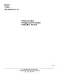
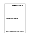
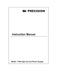
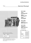
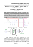
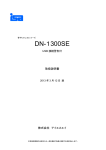
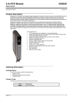
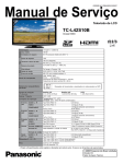
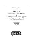
Valco Instruments Co. Inc.
Digital Valve
Sequence Programmer
Instruction Manual
MAN-DVSP
Rev. 1/93
Printed in USA
P. O. Box 55603, Houston, TX 77255
(713) 688-9345 • Sales toll-free (800) 367-8424
Fax (713) 688-8106
Table of Contents
1. GENERAL DESCRIPTION...............................................................................1
2. IMPLEMENTATION...........................................................................................2
2.1 Solenoid Valves
2.11 110 VAC
2.12 12 VDC
2.13 Valco MSVA
2.14 Pulsed Operation of Solenoids
2.2 Valco Electric Actuators
2.21 Multiposition
2.22 Two position
2.3 Valco Digital Valve Interface (DVI)
3. SWITCH AND DISPLAY FUNCTIONS ............................................................7
3.1 Operating the DVSP by Remote Contact Closure
4. DEMONSTRATION SEQUENCE .....................................................................8
5. TECHNICAL DRAWINGS ...............................................................................11
6. WARRANTY....................................................................................................23
1.
GENERAL DESCRIPTION
The Digital Valve Sequence Programmer (DVSP) is an add-on or stand-alone
timer/programmer available with either 2 or 4 intervals, settable in ranges of 0-99
seconds, 0-9.9 minutes, or 0-99 minutes. The DVSP is most commonly used for
remote operation of electrical devices such as solenoid valves, Valco two position
or multiposition electric actuators, and the Valco Digital Valve Interface (DVI), which
converts contact closures into pneumatic pulses for switching Valco two position air
actuators.
The DVSP has two operational modes: in the AUTO mode, the DVSP will return to
the first interval and begin another sequence after the last interval is completed,
and in the SINGLE CYCLE mode it stops after one sequence. During a cycle or
sequence, simple controls allow the user to stop the cycle, reset it to Interval 1,
switch to the AUTO mode, or advance to the next interval. The DVSP can also be
wired for remote operation by contact closure from a data system or other control
device.
Each interval has one DPDT (double pole, double throw) relay, which provides two
sets of contacts with no connection from one side to the other. This means that a
single interval can be used to perform two separate functions requiring differing
voltage requirements. For example, one side of relay A (Interval 1) can be used to
switch an electric actuator (contact closure) while the other side is connected to
110 VAC and switches a 110 VAC solenoid valve at the same time as the electric
actuator. In addition, Relay E (functional only in the AUTO mode) supplies a two
second contact. When solenoid valves are wired in series with this relay the result
is "pulsed operation" of the air actuator, which avoids the potential valve and actuator problems associated with continuously-applied air pressure.
Both 12 VDC and 110 VAC power supplies are included within the DVSP, but the
relays may be supplied from any external power source. For example, 24 VDC
solenoid valves can be switched by the DVSP relays if the 24 volts is supplied to
the relays from an external 24 VDC power supply.
SPECIFICATIONS
General
3-wire power cord (2 meters)
Externally accessible 2A fuse
95-130 VAC, 25-60 Hz
2 or 4 intervals; settable from 0 - 99 seconds, 0 - 0.9 minutes, or 0 - 99 minutes
DPDT relay contacts rated at 3 amps @120 VAC resistive load
Elapsed time display
Dimensions
30 cm (11.8") x 15 cm (6") x 6 cm (2.4")
Weight: 2 Kgm (4 lbs)
Accuracy
2.16 seconds/day maximum error
Temperature range
0 - 70°C
Power Consumption
110 VAC @ 50 mA
12 VDC @ 200 mA
1
2.
IMPLEMENTATION
Before removing the top cover of the DVSP, make certain that the power
cord is unplugged.
Remove the two screws on the upper rear panel which secure the top cover. Look
at Figure 1 to locate the two barrier terminal strips located near the center of the
large printed circuit board. The terminals are grouped beside letters denoting relays A, B, C, and D, and are marked C for Common, NO for Normally Open, and
NC for Normally Closed. For convenience, the power line (fused and switched) is
connected to two of the terminals on the DVSP mother board, labelled HOT and
NEUT. HOT is the high side of the line and NEUT is the low side.
TERMINAL STRIPS
HOLE FOR WIRING
PIN FOR REMOTE "RUN"
PIN FOR
REMOTE "STOP"
TERMINALS FOR
ADDITIONAL RELAY WITH
TWO SECOND CONTACT
LOGIC
BOARD
PIN FOR
REMOTE
"GROUND"
PIN FOR
REMOTE
"+12"
GRND
+12
NEUT
HOT
Figure 1: View of DVSP with cover removed
For operation of devices requiring line voltage (1 amp max), one side of the device
is connected directly to the NEUT terminal and the HOT is switched by the output
relays. For devices which operate on 12 VDC (300 mA max), voltage can be
supplied to any of the relays with a simple jumper connection between the terminal
marked 12 and the Common terminal of the target relay. (Figure 2) Any external
power source can be connected to a Common in the same manner, with a hole
provided in the rear panel to allow a passage for all the external wiring.
The DVSP output relays are double pole, double throw (DPDT), meaning that they
have two separate sets of contacts with no connection from one set to the other.
One contact of each set is the common (C), which is connected to the normally
closed (NC) contact when the DVSP is not in the interval corresponding to that
relay. As the DVSP enters each interval, the corresponding relay switches and
connects the common (C) terminal to the normally open (NO) terminal, sending
the current to the external device.
2
The table below indicates which group of terminals applies to each interval for the
various DVSP models. In the drawings which illustrate the different wiring options,
the terminal groupings are chosen purely for convenience: there is no intent in
these drawings to convey any information about specific intervals.
DVSP-2
Interval 1
Relay A
DVSP-4
Interval 2
Interval 1
Relay C
Relay A
Interval 2
Relay B
Interval 3
Relay C
Interval 4
Relay D
2.1 Solenoid Valves
2.11
110 VAC
The steps described below are illustrated in Figure 2.
1. Supply 110 VAC by connecting the HOT terminal to C of the appropriate
relay.
2. Connect one wire of the solenoid to the NEUT terminal.
3. Connect the other wire of the solenoid to the normally open (NO) terminal of
the relay which corresponds to the C of Step 1.
2.12
12 VDC
The steps described below are
illustrated in Figure 2.
12 VDC SOLENOID
110 VAC SOLENOID
1. Supply 12 VDC by connecting
the +12 terminal to C of the appropriate relay.
2. Connect one wire of the solenoid to the GRND terminal.
3. Connect the other wire of the
solenoid to the normally open
(NO) terminal of the relay which
corresponds to the C of Step 1.
Figure 2: 12 VDC and 110 VAC solenoids
3
2.13
Valco MSVA
The MSVA is used with a two position air actuator, which requires
one interval to switch to the inject position and another to switch to
the load position. The steps described below are illustrated in
Figure 3.
1. Supply the proper voltage (110 VAC in this example) by
connecting the HOT terminal to C of the one of the groups of
terminals to be used, and jumping it to C of the other.
2. Connect one wire of each solenoid to the NEUT terminal.
3. Connect the other wire of each solenoid to the NOs which
correspond to the Cs of Step 1, according to the desired
switching sequence.
Figure 3: 110 VAC Valco MSVA
2.14
Pulsed Operation of Solenoids
The first three procedures demonstrate the simplest uses of the DVSP. This
example will illustrate the use of the pulsed relay in conjunction with two devices
on the same DPDT relay. The steps described below are illustrated in Figure 4.
1. Connect the two wires of the 12 VDC
solenoid as described in Section 2.12.
12 VDC SOLENOID
110 VAC SOLENOID
2. Connect one wire of the 110 VAC solenoid to NEUT as described in Section
2.11, but connect the other wire to the
second NO terminal of the same relay
to which the 12 VDC solenoid is connected.
3. Supply 12 VDC by connecting the +12
terminal to one of the NO terminals on
the pulsed relay (Figure 1) and
connecting that NO’s related Common
to the Common of the NO which has
the 12 VDC solenoid connected to it.
4. Likewise, supply 110 VAC by connecting
the HOT terminal to the remaining NO
terminal on the pulsed relay and
connecting that NO’s related Common
to the Common of the NO which has
the 110 VAC solenoid connected to it.
TERMINALS FOR
EXTRA RELAY
WITH TWO SECOND PULSE
Figure 4: Use of the pulsed relay and
two events on one relay
4
2.2 Valco Electric Actuators
Multiposition actuators require only one event to step the valve/actuator to its next
position. However, the two position actuator requires two intervals: one to switch
the two position valve to its inject position and another to switch it to its load
position.
2.21
Multiposition
The steps below are illustrated in Figure 5.
GREY WIRE
WHITE WIRE
1. Locate the two pairs of adjacent grey and
white wires in the interface cable supplied with
the actuator. The relevant pair for this application is the one near the center of the ribbon
cable.
2. Connect the grey (STEP) wire to the NO
terminal of the appropriate relay.
Figure 5:
Valco multiposition electric actuator
3. Connect the white (GRND) wire to C or the
same relay.
2.22
BLACK WIRE
Two position
The steps below are illustrated in Figure 6.
1. Locate the black, red, and green wires in the
remote switching cable extending from the
cover of the actuator.
2. Connect the black (INJECT) wire to the NO
terminal of the appropriate relay for the desired interval.
GREEN WIRE
RED WIRE
Figure 6:
Valco two position electric actuator
3. Connect the red (LOAD) wire to the NO
terminal of the relay corresponding to the
interval where sample is to be loaded.
4. Connect the green (GRND) wire to the
Common of one of the relays and use a
jumper to connect it to the Common of the
other relay.
5
2.3 Valco Digital Valve Interface (DVI)
Two intervals are required with the DVI: one to signal it to
move the valve to the inject position, and one to signal it
to return to the load position. The steps described below
are illustrated in Figure 7.
DIGITAL VALVE
INTERFACE
1. Connect the air actuator to the DVI as described in
the DVI literature.
2. Locate the blue, black, and red wires in the interface
cable supplied with the DVI.
3. Connect the blue (INJECT) wire to the NO terminal
of the appropriate relay for the desired interval.
4. Connect the black (LOAD) wire to the NO terminal
of the relay corresponding to the interval where
sample is to be loaded.
BLUE WIRE
5. Connect the red (GRND) wire to the Common of
one of the NOs used in Steps 3 and 4, and use a
jumper to connect it to the Common of the other
NO.
In routine operation the DVSP will control the
switching of the valves, so manual control through
the DVI will not be an issue. However, it is possible
to allow the option of manually overriding the positioning of valves switched by the DVI. To do this, the
DVSP signal must be removed from the DVI remote
cable by routing the DVI common (RED) through the
pulsed relay, E. The signal from the DVSP is applied for only two seconds and then removed, permitting subsequent manual valve positioning with
the switch on the front of the DVI.
6
RED WIRE
BLACK WIRE
Figure 7: Valco Digital Valve Interface
3.
SWITCH AND DISPLAY FUNCTIONS
1. Power ON/OFF: Turns the DVSP on and off.
2. Interval duration switches: Each interval has two thumbwheel switches for
setting the the interval duration, in increments determined by the setting of
the time unit switches.
3. Time unit switches: Under each pair of interval duration switches is a
three-position switch which defines the units in which the duration is set.
With this switch to the left the unit is minutes, so the two digits of the duration switches reflect a value from 00 to 99 minutes. In the middle position
the unit is tenths of a minute, with a range of 0.0 to 9.9 minutes. (In this
setting the elapsed time display shows a decimal point.) When the switch is
to the right the thumbwheel duration switches are setting seconds, in a
range from 00 to 99.
4. ADVance button: This will advance the DVSP into the next non-zero interval. Everything functions as if the timer had reached its setting and advanced to the next interval on its own.
5. AUTO button: Pushing this button toggles the DVSP in and out of the AUTO
mode. In the AUTO mode (AUTO LED on), when a cycle is completed the
DVSP goes back to the first interval and starts another. In the SINGLE
CYCLE mode (AUTO LED off), the timer stops at the end of the last interval.
6. ReSeT button: Pressing this button sets the DVSP to the state it’s in when
first turned on: the timer is stopped and the DVSP is in the SINGLE CYCLE
mode. No interval is being addressed and no relays are energized.
7. RUN button: Pressing this button lights the RUN LED, starts the timer, and
moves the DVSP to the first interval not set to "00".
8. STOP button: This stops the timer and resets it to zero, but the DVSP
remains in the interval that was in progress and the output to the relays
stays the same. The RUN LED goes off.
9. Current interval lights: Between each time unit switch and interval number
is an LED which comes on when that interval is current.
10. Elapsed time readout: This digital display to the left of the VICI logo shows
the elapsed time in the interval which is running, indicated by which current
interval light is on. The display is in the value range selected by the three
position time unit switch for that interval. Whenever the timer is counting
minutes, the decimal light flashes at one second intervals.
3.1 Operating the DVSP by Remote Contact Closure
The DVSP can be wired so that the functions done by RUN, STOP, and AUTO
buttons can be done by remote contact closure. This involves soldering wires from
the control device to the appropriate pins on the logic board. (Figure 1) For the
RUN function, establish momentary contact between pins 18 and 35 (+12). For
the STOP function, momentarily connect pins 17 and 35. Connecting pin 22 to pin
34 (ground) will toggle the DVSP in and out of the AUTO mode.
7
4.
DEMONSTRATION SEQUENCE
This example demonstrates use of the DVSP-4 to control the positioning of two
Valco switching valves. Valve 1 (V1) is used for sample injection and Valve 2 (V2)
is configured for column backflushing. Both valves are air actuated, but V1 is
controlled by a Valco Digital Valve Interface (DVI) while V2 is controlled by a pair of
3-way solenoid valves (MSVA). Each valve requires two intervals of the DVSP;
one for clockwise rotation and one for counterclockwise. (All references to directions are as seen from the actuator end of the valve.)
In the ready (rest) state, both valves are in the counterclockwise position. (Figure
8) After the process is begun by charging the sample to V1, V1 will be switched
clockwise to inject the sample. (Figure 9) After two seconds for sample injection,
V1 is returned to the counterclockwise position to load the next sample. In this
example, fifteen minutes will elapse before V2 is switched clockwise and the
contents of the column are backflushed to the detector. (Figure 10) After nineteen
minutes for desorbtion of the column contents into the detector, V2 is switched
counterclockwise for the next sample analysis. Four and a half minutes will be
allowed for equilibration before the next cycle begins.
V2
CARRIER IN
SAMPLE OUT
SAMPLE IN
COLUMN
TO DETECTOR
Figure 8: V1 and V2
in counterclockwise
position
(Rest and Intervals 2, 4)
Figure 9: V1 in
clockwise
position
(Interval 1)
Figure 10: V2 in
clockwise
position
(Interval 3)
Broken down into its component intervals, the process appears like this:
Interval 1 (2 seconds)
Relay A is energized, switching V1 to its clockwise position and injecting the
sample onto the column.
Interval 2 (15 minutes)
Relay B is energized, switching V1 back to the counterclockwise position,
ready for the next sample.
Interval 3 (19 minutes)
Relay C is energized for two seconds (through relay E), switching V2 and
backflushing the column to the detector.
Interval 4 (4.5 minutes)
Relay D is energized for two seconds (through relay E), switching V2 to the
column forward position, ready for the next run. If the DVSP is in the AUTO
mode, the next cycle will begin after 4.5 minutes.
8
Valco Instruments Co. Inc.
m
s
m x .1
1
m
s
m x .1
2
m
s
m x .1
3
m
s
m x .1
4
AUTO
RUN
POWER
Figure 11: DVSP front panel
programmed for the demonstration process
Programming the DVSP is very simple now that the process has been broken into
steps:
1. Set the switch beside the "1" to the right, for "seconds", and set the
thumbwheel switch to 02.
2. Set the switch beside the "2" to the left, for "minutes", and set the
thumbwheel switch to 15.
3. Set the switch beside the "3" to the left, for "minutes", and set the
thumbwheel switch to 19.
4. Set the switch beside the "4" in the middle, for "tenths of minutes", and set
the thumbwheel switch to 45 (4.5 minutes).
The wiring connections for the demonstration sequence are illustrated in Figure
12. Since V1 uses the DVI (with a built-in two-second relay) it is simply wired to
DVSP relays A and B which correspond to Intervals 1 and 2. (A jumper connects
the Commons.)
Since V2 is switched by a pair of solenoid valves, it is important that the current
which activates them is supplied only as long as it takes to switch the valve, even
though the DVSP relay is energized for the entire length of the interval. To provide
this pulsed current and avoid the problems associated with continuously-applied air
pressure, the DVSP features a fifth relay (E) which is activated for two seconds at
the beginning of each interval. When the "hot" leg of each solenoid is run through
relay E, the power is applied to the solenoid only during the initial two seconds of
its interval.
9
VALVE 1
VALVE 2
INTERVAL 2
INTERVAL 4
INTERVAL 3
INTERVAL 1
4
2
3
AIR IN
1
AIR IN
BLACK WIRE
RED WIRE
BLUE WIRE
TERMINALS FOR RELAY "E"
WITH TWO SECOND PULSE
Figure 12: DVSP connections for the
demonstration process
10
5.
TECHNICAL DRAWINGS
Digital Valve Sequence Programmer Assy .................. Drawing 21143
Page 12
Mother Board Assy, Four Interval DSVP ..................... Drawing 21027
Page 13
Schematic - DVSP Mother Board ................................ Drawing 21212
Page 14
Logic Board Assy ......................................................... Drawing 21061
Page 15
Schematic - Logic Board.............................................. Drawing 21030
Page 16
Digiswitch Interface Board Assy................................... Drawing 21088
Page 17
Schematic - Digiswitch Interface Board Assy .............. Drawing 21188
Page 18
Pushbutton Board Assy................................................ Drawing 21059
Page 19
Schematic - Push Button Board Assy.......................... Drawing 21062
Page 20
TWS Board Assy, Four Interval DVSP ......................... Drawing 21023
Page 21
Schematic - TWS Board Assy, Four Interval DVSP..... Drawing 21294
Page 22
11
1
21
21
27
2
13
12
E F
8
FOR 220 VERSION
COVER SILKSCREEN
w/220 VAC TAG
9
m
18
19
7
CONNECTIONS
23
s
mx.1
7
7
1
m
s
mx.1
1
1
2
m
mx.1
s
7
7
3
m
mx.1
1
s
VOLTS
S/N
DIGITAL VALVE SEQUENCE PROGRAMMER
BOARD NO 21060
**
50/60 Hz
**
FUSE 2A
120 VAC
11
E
US
F US
12
E
FUS
1
3
4
6
Made in USA
AUTO
ADV
22
RUN
RST
5
10
4
25
STOP
11
BLK
POWER
Valco Instruments Co. Inc.
RUN
26
WHT
USE HEAT SHRINK
COMPOUND
MADE IN THE USA
AUTO
INSERT FROM
INSIDE
50/60 Hz
MODEL
Valco Instruments Co., Inc.
1
20
11
4
14
25
FROM POWER
CABLE-BLACK
(220V-BROWN)
15
14
SIDE VIEW
SHRINK
TUBING
17
16
24
21
*
*
*
REVISIONS
DESCRIPTION
DATE
2
1
1
1
4
6
1
1
.500
.250
.041
1
1
HWLUG-4218B
HWLUG-1806-HT
I-21061
HWGR-2177
HW-1658
HWSC-SM4-6
HW-MICA
I-21988
I-W-18-BLACK
I-STUBE.500
I-STUBE.250
I-21110
MANUAL:DVSP
LUG: FEMALE SLIP-ON, 16-14 AWG
LUG: RING, HIGH TEMP. #6
PCB ASSY: LOGIC BOARD, DVSP/TGA 1K
GROMMET: NEOPRENE, 5/8 x 1/16 x 7/16 ID
FEET: RUBBER STICK-ON
SCREW, SMS: #4*3/8 LG
MICA INSULATORS #4671
TAG: SERIAL, ALL ELEC. DEVICES
WIRE: 18 AWG TEFLON BLACK
TUBING: HEAT SHRINK 1/2" ID
TUBING: HEAT SHRINK 1/4" ID
RETAINER: DVSP PUSHBUTTON BD
(NOT SHOWN)
MANUAL: OPERATION, DVSP
I-W-17800
SUB-DIR
DVSP
21143
12/16/82
DATE
FILE NAME
CHECKED
DESIGNED
DJM
DRAWN
APPROVED
TOLERANCES UNLESS
63
OTHERWISE SPECIFIED
FRACTIONS
DEC.
ANGLES
.X.1
1/64"
1
.XX.01
.XXX.005
B
SIZE
USA PROJECTION
---
SCALE
DO NOT SCALE DRAWING
SHEET
OF
DVSP4
21143
DRAWING NO.
PROGRAMMER ASSY.
DIGITAL VALVE SEQ.
Valco Instruments Co., Inc.
THIS DOCUMENT AND THE INFORMATION WHICH IT CONTAINS SHALL NOT BE USED, EXPLOITED
OR SOLD, AND SHALL NOT BE REVEALED OR DISCLOSED TO OTHERS WITHOUT THE EXPRESSED
WRITTEN PERMISSION OF VALCO. THIS DOCUMENT SHALL REMAIN THE PROPERTY OF VALCO
AND SHALL BE RETURNED UPON DEMAND.
12
2
I-21027-220
1
1
2
3
1
1
1
2
2
1
7
1
1
1
2
QTY
INITIATED
J DURR
I-21109
I-21027
HWSC-PL4-10
HWNUT-HEX#4
I-21059
I-21119
I-21023
HWSC-BM2-8
HMNUT-HEX#2
I-21164
HWSC-PL4-4
I-W-CS-21
HWSRR-10
HWFUSEHOLD-1
HWFUSE-2A
VALCO #
04/21/99
ENCLOSURE: DVSP-4 (TENEC E2231-J12)
PCB ASSY: M/B, FOUR INTERVAL DVSP
SCREW,PLMS: 4-40 x 3/4 LG
NUT, HEX: #4-40 UNC, STAINLESS
PCB ASSY: PUSH BUTTON BD,DVSP/TGA1K
LENS: DISPLAY, RED. INSTRUMENTS
PCB ASSY: T/W SWITCH, FOUR INTERVAL DVSP
SCREW, BMS: 2-56 x 1/2 LG
NUT, HEX: #2-56 UNC
RETAINER ARM: DVSP PUSHBUTTON BD
SCREW, PLMS: 4-40 *1/4 Lg, PANHD
POWER CORD: GREY 6' 18/3 SVT
STRAIN-RELIEF: SRR-10
FUSE-HOLDER: 342014
FUSE: 2AMPS 3 AG
DESCRIPTION
ECN#:4821 BRING UP TO STANDARD, REDRAWN IN ACAD
220 MODELS USE
17
18
19
20
21
22
23
24
25
26
27
28
1
2
3
4
5
6
7
8
9
10
11
12
13
14
15
16
ITEM
A
LTR
13
Valco Instruments Co. Inc.
S1
CO2
L1
CO5
CO1
VIEW A-A
INSTALLED ON BACK
OF BOARD
S2
R5
A
A
RN1
REG
RN2
CO6
L2
C6
C3
S3
C2
C1
L3
Z2
S4
L4
R1
CO10
CO8
INSTALL MICA INSULATOR
UNDER S3 AND S4
Z4
CO4
CO3
PCB
L5
CO11
CO9
NW
R2
R3
R4
L6
RA
RLY2
RLY1
C4
CO12
MT
SC
NUT
CO7
T1
RLY3
RLY4
C5
B-21143
REVISIONS
DESCRIPTION
DATE
SUB-DIR
\DVSP\
FILE NAME
1/5/97
DATE
21027
CHECKED
DESIGNED
R.B.D.
DRAWN
APPROVED
TOLERANCES UNLESS
63
OTHERWISE SPECIFIED
FRACTIONS
DEC.
ANGLES
.X.1
1/64"
1
.XX.01
.XXX.005
B
SIZE
USA PROJECTION
---
SCALE
OF
I-21027
SHEET
21027
DRAWING NO.
FOUR INTERVAL DVSP
PCB ASSY: MOTHER BD
Valco Instruments Co., Inc.
QTY
1
1
1
1
1
2
1
2
1
4
1
4
3
2
3
1
1
1
4
1
6
5
1
6
2
2
2
2
2
INITIATED
J DURR
VALCO #
I-PCB21024
I-RN761-1-10K
I-RN761-1-220K
I-IC4072
I-IC2004
I-CE227-35AL
I-CT475-35
I-CC103-1K
I-CT105-35
I-R511201
I-R515102
I-T09523103
I-T09523101
I-T4596-6
I-T4382-6
I-T4109-6
I-IC7812
I-D-VE28
I-SW-7103MD
I-SW-MTM106
I-LED550-01
I-RY-NC2DPDC12
I-X-SSC-16-1
HWSO-4639B
HW-607
HWSC-PL4-4
HWNUT-HEX#4
HWW-N#4
HW-MICA
11/16/82
01/07/98
THIS DOCUMENT AND THE INFORMATION WHICH IT CONTAINS SHALL NOT BE USED, EXPLOITED
OR SOLD, AND SHALL NOT BE REVEALED OR DISCLOSED TO OTHERS WITHOUT THE EXPRESSED
WRITTEN PERMISSION OF VALCO. THIS DOCUMENT SHALL REMAIN THE PROPERTY OF VALCO
AND SHALL BE RETURNED UPON DEMAND.
REF DWG (21212) SCHEMATIC
PARTS LIST
DESCRIPTION
PCB: MOTHER BOARD DVSP AW108 REV M
RES NET: 10 K, 16 PIN DIP, COMMON
RES NET: 220 K, 16 PIN DIP, COMMON
IC: 4 INNPUT OR-GATE
IC: 7 BUFFER/LINE DRIVER
CAP: ELECT, 220uF 35V, AXIAL LEAD
CAP: TANTAL, 4.7MF 35V
CAP: CERAMIC, .01uF 1000V
CAP: TANTAL, 1MF 35V
RES: 1.2 K, 5%, 1/4W
RES: 51 K, 5%, 1/4W
CONN: 10 PIN PCB MOLEX
CONN: 10 PIN RT ANGLE MOLEX
CONN: GS 5/10 WEIDMULLER #4596-6
CONN: GS 5/4 WEIDMULLER 4382-6
CONN: GS 5/2 WEIDMULLER #4109-6
IC: VOLTAGE REGULATOR, 12V, T0220
RECTIFIER BRIDGE
SWITCH: SPDT 7103MD9AB SPDT-RPC-C-P-S
SWITCH: TOGGLE SPDT-RPC-N-P-S
LED: RED, WITH MOUNT 550-0405 DIALIGHT
RELAY: AROMAT 12V DC
TRANSFORMER 16 VCT .6 AMP 120V
STANDOFF: #4-40 X .1875 SWAGE THREADED
MALE TABS
SCREW,PLMS: 4-40 X 1/4 LG
PH,SS
NUT, HEX: #4-40 UNC, STAINLESS
WASHER: SHOULDER, #4 HHS-2661 NYLON
MICA INSULATORS #4671
SO1-6
INSTALL ON
BOTTOM OF PCB
MOVE S1-S4 & Z3 ADD C4-6 MOVE INPUT POWER TERM.
ECN #4027 REDRAWN IN ACAD UPDATE BOM
DES
PCB
RN1
RN2
Z4
Z2
C1,2
C3
C4,5
C6
R1-4
R5
CO1-4
CO5-7
CO8,9
CO10-12
CO13
REG
RA
S1-4
S5
L1-6
RLY1-5
T1
SO1-6
MT
SC
NUT
NW
MICA
NEXT ASSY
S5
CO13
MT
SC
NUT
RLY5
N
P
LTR
14
CO5
6
5
7
4
2
1
3
+12
15
14
13
12
11
9
8
10
TO TWS ASSY I-21025, 27
SCHEMATIC - 21294 OR 21296
1 2 3 4 5 6 7 8 9 10 11 12 13 14 15 16 17 18 19 20
16
RN1 (Z1)
C06
+12
1 2 3 4 5 6 7 8 9 10
PLS 2
MIN
SEC
PULSE
PULSE
RUN LT
XST
START
STOP
M8
M4
M1
M2
L8
L4
L1
L2
CO7
ADV
AUTO
XCNT
ADA
ADB
XSTOP
XHOLD
RST
AUTOLT
OUT2
OUT1
OUT4
OUT3
GND
+12
POR
CLOCK
DP
XHOLD
RESET
LOGIC BOARD ASSY
21061
SCHEMATIC- 21030
TO PUSHBUTTON ASSY I-21059
SCHEMATIC- 21062
R2
1.2K
CO2
7
6
5
4
3
2
1
20
19
18
17
16
15
14
13
12
11
10
9
8
CO1
S1
3
2
4
S2
13
5
12
S3
11
S4
9
R3
1.2k
+12
L6
+12
R4
1.2k
10
L1
L2
L3
D
C
B
A
RLY4
RLY3
RLY2
RLY1
CO9
CO11
CO10
CO8
NC
NC
C
NO
NC
NEUTRAL
HOT
GND
+12
C
NO
NC
C
NO
NC
C
NO
NC
C
NO
4
7
8
12
2
6
3
11
5
10
13
9
1
14
RN2 (Z3)
220K
RUN
AUTO
L5
INTERVALS
E
L4
R1
1.2k
+12
+12
RLY5
C
NO
NC
C
NO
NC
FUSE
S5
2 AMP
3AG
C1 220uF
REG
7812
+12
.01uF
C5
GREEN
WHITE
C2 220uF
RA
.01uF
C4
BLACK
DATE
7JUN99
16V CT
T1
INITIATED
JDURR
SUB-DIR
/DVSP/
FILE NAME
06-07-99
DATE
21212
CHECKED
DESIGNED
JDURR
DRAWN
APPROVED
TOLERANCES UNLESS
63
OTHERWISE SPECIFIED
FRACTIONS
DEC.
ANGLES
.X.1
1/64"
1
.XX.01
.XXX.005
C
SIZE
USA PROJECTION
SCALE
BOARD, DVSP
SHEET
21212
DRAWING NO.
SCHEMATIC: MOTHER
Valco Instruments Co., Inc.
OF
THIS DOCUMENT AND THE INFORMATION WHICH IT CONTAINS SHALL NOT BE USED, EXPLOITED
OR SOLD, AND SHALL NOT BE REVEALED OR DISCLOSED TO OTHERS WITHOUT THE EXPRESSED
WRITTEN PERMISSION OF VALCO. THIS DOCUMENT SHALL REMAIN THE PROPERTY OF VALCO
AND SHALL BE RETURNED UPON DEMAND.
CO12
CO13
C
NO
NC
C
NO
NC
C
10
11
7
NO
7
+12
12
4
5
14
13
3
6
16
15
9
2
+12
1
8
Z2
2004
Z4
14
+ C3
4.7 uF
REVISIONS
DESCRIPTION
CHANGE FROM HAND DWG TO CAD
4072
1
+12
INTERVAL TIME SELECT SWITCHES
CO4
34
35
36
37
38
39
40
21
22
23
24
25
26
27
28
29
30
31
32
33
CO3
R5 51K
A
LTR
15
I-IC4018
I-IC4020
I-IC4049
RES: 100 K, 5%,1/4W
CAP: CERAMIC,.022 uF,50V,.250 LEADS
CAP: TANAL,.47 MF 35V
CAP: CERAMIC VARIABLE, JFD-DV2PS120D
CAP:TANTAL, 47MF 35V
CAP: CERAMIC 47pf 1000V
CRYSTAL: 2.097152 MHZ -MP2
IC: DUAL 4-INPUT AND GATE
IC: 4-INPUT OR GATE
IC: QUAD 2-INPUT AND GATE
IC: QUAD 2-INPUT OR GATE
IC: QUAD 2-INPUT NAND GATE
IC: BCD UP/DOWN COUNTER
IC: DECIMAL CTR/DIVIDER, RCA OR MOT
IC: DUAL 4-BIT STATIC SHIFT REGISTER
IC: DUAL TYPE D FLIP-FLOP
IC; ANALOG MUX/DEMUX
IC: DUAL 4-INPUT AND GATE
IC: HEX INVERTER
IC: PRESET DIVIDE-BY-N COUNTER
IC: 14 BIT BINARY COUNTER
IC: INVERTING HEX BUFFER
SCHEMATIC C-21030
R14
C1;3-6&17
C7-10
C11
C2;12-16
C18
XTAL
Z1
Z2 & 7
Z3 & 14
Z4
Z5
Z6 & 11
Z8
Z9
Z10 & 16
Z12
Z13
Z15
Z17 & 18
Z19 & 20
Z21
REF.
I-IC4015
I-IC4013
I-IC4052
I-IC4082
I-IC4069
RES: 220 K, 5%, 1/4W
RES: 47K, 5%, 1/4W
RES: 12 MEG, 5%, 1/4W
RES: 10 K, 5%,1/4W
R4-6
R7-9
R12
R13 & 15
I-IC4093
I-IC4510
I-IC4017
I-IC4071
I-CV9410-4
I-CT105-35
I-CC470-1K
I-XTAL-4
I-IC4002
I-IC4072
I-IC4081
I-R511003
I-CC223-50
I-CE474-35
I-R512203
I-R514702
I-R51205
I-R511002
I-T09641101
I-R511001
PLUG: 10 PIN MOLEX
RES: 1 K, 5%, 1/4W
P1-4
R1-3;10,11
QTY.
2 EA.
2 EA.
1 EA.
1 EA.
1 EA.
1 EA.
2 EA.
1 EA.
1 EA.
2 EA.
1 EA.
1 EA.
1 EA.
6 EA.
1 EA.
1 EA.
1 EA.
2 EA.
2 EA.
1 EA.
6 EA.
4 EA.
3 EA.
3 EA.
1 EA.
2 EA.
4 EA.
5 EA.
1 EA.
CIRCUIT BD.
I-PCB21060
CONNECTOR
I-T08641101
USE SPECIAL JIG TO
PRESS PINS OF
CONNECTOR
.350
P2
P1
INSTALL P1-P4
ON OTHER SIDE
OF BOARD
C5
REV. NO L
ASSY NO 21061
ARTWORK NO 105
C1
R2
C15
R3
C16
R1
C14
C3
BOARD NO 21060
+
+
+
C7
C2
+
+
C9
Z11
Z16
Z12
+
+
+
C11
R11
R14
P4
J.D.
3/2/93
P3
INITIATED
DATE
SUB-DIR
DVSP
FILE NAME
11/30/90
DATE
21061
CHECKED
DESIGNED
D.K.W.
DRAWN
APPROVED
TOLERANCES UNLESS
63
OTHERWISE SPECIFIED
FRACTIONS
DEC.
ANGLES
.X.1
1/64"
1
.XX.01
.XXX.005
B
SIZE
USA PROJECTION
---
SCALE
DO NOT SCALE DRAWING
DVSP/TGA1K
SHEET
OF
I-21061
21061
DRAWING NO.
PCB ASSY:LOGIC BOARD
Valco Instruments Co., Inc.
THIS DOCUMENT AND THE INFORMATION WHICH IT CONTAINS SHALL NOT BE USED, EXPLOITED
OR SOLD, AND SHALL NOT BE REVEALED OR DISCLOSED TO OTHERS WITHOUT THE EXPRESSED
WRITTEN PERMISSION OF VALCO. THIS DOCUMENT SHALL REMAIN THE PROPERTY OF VALCO
AND SHALL BE RETURNED UPON DEMAND.
COMPONENT SIDE OF BOARD
Z21
R12
R13
Z20
C18
Z19
C6
Z15
Z18
Z14
C17
R7
R8
R9
Z17
Z13
Z10
Z9
C8
Z8
+
Z7
C4
+
Z6
R4
Z3
R6
Z5
Z2
R5
Z4
Z1
4510
VALCO #
4018
I-PCB21060
PCB: LOGIC BOARD AW105 REV L
ECN #035 ADD C18 SEE
ECN #1083 ADD ORIENTATION ON BOARD
4082
4018
SYMB.
P.C.B.
A
B
REVISIONS
DESCRIPTION
4002
4081
4020
4510
4072
4072
4052
4017B
4081
4015
4071
4013
4069
4020
PARTS LIST
DESCRIPTION
LTR
R10
R15
4093
4013
XTAL
4049
C12
C13
C10
R14
100K
11
13 CK 10
Q R
8
12
Q S
D
9
Z10
1/2 4013
11
13 CK 10
Q R
8
12
Q S
D
9
Z16
1/2 4013
6
Z21
7 4049
5
Z5
6 4093
2
Z21
3 4049
SPARES
OUT3 33
OUT4 32
OUT1 31
OUT2 30
RESET 40
PLS2 1
PULSE 5
PULSE 4
128 HZ 8
XCNT 23
+12
4
Z21
4049
R13
10K
.39uf
C10
11
+
12
15
2
5
5
4
3
2
1
RUN
1 14
6
5 DQ
S
2 Q
CK 3
R
4
7
Z10
1/2 4013
POR
ADVPLS 10
2
3
4 Z2
5 4072
36
C15
1uf
R2 1K
C14
1uf
R1 1K
Z1
4002
BEGIN
AGAIN
13
12
RUN 9
10 Z2
11 4072
29
C16
1uf
1K
13
4
11 Z13
9 4082
10
12
NEXT
18 19
10
R3
9
12 Z1
11 4002
10
RUN
START
Z3
6 4081
5
Z9
1/2 4015
4
INTRES
10
3 NEXT
20
Z4
4071
4
CKA
3 END
Z14
4081
Z15
3 4069
8
8 Z14
9 4081
1 Z14
2 4081
PRE
Z17
8 4018
10
16
15
RES
1 60TH
14 CK
DAT
13
17
R10 1K
C12
1uf
9
8
1
AUTOLT
2
Z3
1 4081
6
5
Z15
9 4069
1
6
16
DAT
PRE
Z17
8 4018
10
15
SEC RES
14 CK
26
NC
NC
5
2 Z7
3 4072
4
POR
INTADV
12
6
5 4 3 10
1 2 3 4 16
7
DAT
9
8
CK
6
HOME
5
Z15
4069
24
3
4
16
CK 14
0 3
5 1
5
6
7 6
CKEN RES 15
Z8
13 8
4017
2 1
4
2
7 3
10 4
POR
7
8
11
Z15
12 Z4
4071
13 4069
13
Q14
3
11
25
4071
Z4
1
5
4071
Z4
6
10
9
4049
Z21
3
Z16
14 3 1/2 4013
CK 4
2
R
Q
1
6
Q
S
D
C7
.02uf
1
Z5
2 4093
Z21
14 4049
12
Z3
4081 13
R4
220K
R9 47K
R15
10K
11
47uf
C18
12 Z14
4081
13
ADB
XHOLD 39
+12
13
ADA
C11
QB
16
3 Q14 Q4 7
CKA
RES
11 8
10 CK
RST
XTEP
4.7pf
10
Z19
11 16 4020
RES
2
10
CK QB
RST
STOP
FREQ. ADJ.
Z15
4069
11
Z20
4020
RUNLT
9
+12
10
9
13
3
C3
.02uf
C4
13
4
+12
+12
220K
R6
220K
R5
12
9
8
R11
1K
Z21
5 4049
C5
.02uf
.02uf
C6
R8
47K
.39uf
C8
R7
47K
.39uf
C9
DATE
5-8-84
7-25-89
ADV
34 GND
35 +12
22 AUTO
21
27 XHLDRST
28 RST
10 L1
9 L2
11 L4
12 L8
14 M1
13 M2
15 M4
16 M8
6 SEC
7 MIN
38 DP
37 CK
INITIATED
SUB-DIR
TGA\1K
21030
07/25/89
DATE
FILE NAME
CHECKED
DESIGNED
M.CHIU
DRAWN
APPROVED
TOLERANCES UNLESS
63
OTHERWISE SPECIFIED
DEC.
ANGLES
FRACTIONS
.X.1
1/64"
1
.XX.01
.XXX.005
C
SIZE
USA PROJECTION
SCALE
DVSP, TGA1K, HCM
SHEET
21030
DRAWING NO.
OF
SCHEMATIC: LOGIC BOARD
Valco Instruments Co., Inc.
THIS DOCUMENT AND THE INFORMATION WHICH IT CONTAINS SHALL NOT BE USED, EXPLOITED
OR SOLD, AND SHALL NOT BE REVEALED OR DISCLOSED TO OTHERS WITHOUT THE EXPRESSED
WRITTEN PERMISSION OF VALCO. THIS DOCUMENT SHALL REMAIN THE PROPERTY OF VALCO
AND SHALL BE RETURNED UPON DEMAND.
Z5
4093
.02uf
11
C2
Z5
4093
1uf
10
C13
1uf
35V
Z15 1
4069
+
13
2
12
9
10 Z7
11 4072
8
Z11
4510
16
4
15 CK
1
7 CO
2 12
5 CKN 3 13
10 DN
4 3
9 RES PEN 1
16
4
15 CK
1
7 CO
2 12
5 CKN 3 13
10 DN
4 3
9 RES PEN 1
RST
8
Z6
4510
INTRES
.02uf
C1
C17
.02uf
Z3
4081
8
1 INTADV
13
REVISIONS
DESCRIPTION
SEE ENGINNERING CHANGE #035
TITLE BLOCK CHANGED, DRAWING IN AUTOCAD
16
1 Y0
Y
SEC 5 Y1
2 Y2
XCNT 4 Y3
X
12 X0
14 X1
A
15 X2
B
11 X3
+12
6 7 8
Z12
4052
L
M
LTR
+
R12 12M
+
+
(RUN)
START
XST
+
2.097152 MHZ
XTAL
+
AUTOLT
+
POR
+
16
17
S1
L1
CO1
Z1
S2
L2
Z2
CO2
CO3
S3
L3
Z3
C1
S4
INSTALL ON OPPOSITE SIDE
L4
R1
PCB
REVISIONS
C03
C01,2
C1
DATE
I-T6092007
I-T09523101
I-CC223-50
I-R511001
I-SW-7103MD
I-LED550-01
I-IC4072
I-RN761-1-220K
I-IC4049
I-PCB21087
PART #
06/15/99
APPROVED
1 EA
2 EA
1 EA
1 EA
4 EA
4 EA
1 EA
1 EA
1 EA
1 EA
QTY
JDURR
SUB-DIR
\TGA\
FILE NAME
06/15/99
DATE
21088
CHECKED
DESIGNED
JDURR
DRAWN
APPROVED
TOLERANCES UNLESS
63
OTHERWISE SPECIFIED
FRACTIONS
DEC.
ANGLES
.X.1
1/64"
1
.XX.01
.XXX.005
B
SIZE
USA PROJECTION
---
SCALE
OF
I-21088
SHEET
21088
DRAWING NO.
INTERFACE, TGA-1K
PCB ASSY: DIGISWITCH
Valco Instruments Co., Inc.
THIS DOCUMENT AND THE INFORMATION WHICH IT CONTAINS SHALL NOT BE USED, EXPLOITED
OR SOLD, AND SHALL NOT BE REVEALED OR DISCLOSED TO OTHERS WITHOUT THE EXPRESSED
WRITTEN PERMISSION OF VALCO. THIS DOCUMENT SHALL REMAIN THE PROPERTY OF VALCO
AND SHALL BE RETURNED UPON DEMAND.
APPLIES TO REV B PCB
CONN: 20 PIN HEADER, RT/ANGLE
CONN: 10 PIN RT ANGLE MOLEX
CAP: CERAMIC, .022uF 50V, .250 LEADS
RES: 1K, 5%, 1/4W
SWITCH: SPDT 7103MD9AB
S1-S4
R1
LED: RED, W/MOUNT, 550-0405 DIALITE
IC: 4 INPUT OR GATE
Z3
L1-L4
RES NET: 220K, 16 PIN DIP, COMMON
IC: INVERTING HEX BUFFER
Z1
Z2
DESCRIPTION
PCB: DIGISWITCH INTERFACE
PCB
PARTS LIST
CHANGE FROM HAND DWG TO CAD
DESCRIPTION
DESC
A
LTR
18
16
Z2
220K
3
6
8
14
1
11
12
7
2
4
15
5
9
13
10
S1
INT 1
M
S
S2
INT 2
M
S3
INT 3
M
ADD JUMPER
S
S
S4
INT 4
M
10
2
4
6
9
3
5
7
8
15
12
1
11
4049
Z1 +12
7
Z3
4072
14
S
9
11
12
10
4
3
5
2
14
+12
L1
1
SEC
13
MIN
C1
L2
.02 uF
L3
L4
R1
1.2k
+12
CO1
1
3
5
7
9
11
13
15
17
19
+12
REVISIONS
DESCRIPTION
DATE
06/15/99
APPROVED
JDURR
SUB-DIR
\TGA\
FILE NAME
06/15/99
DATE
21188
CHECKED
DESIGNED
JDURR
DRAWN
APPROVED
TOLERANCES UNLESS
63
OTHERWISE SPECIFIED
ANGLES
FRACTIONS
DEC.
.X.1
1/64"
1
.XX.01
.XXX.005
B
SIZE
USA PROJECTION
---
SCALE
SHEET
21188
DRAWING NO.
INTERFACE BD., TGA-1K
OF
SCHEMATIC: DIGISWITCH
Valco Instruments Co., Inc.
THIS DOCUMENT AND THE INFORMATION WHICH IT CONTAINS SHALL NOT BE USED, EXPLOITED
OR SOLD, AND SHALL NOT BE REVEALED OR DISCLOSED TO OTHERS WITHOUT THE EXPRESSED
WRITTEN PERMISSION OF VALCO. THIS DOCUMENT SHALL REMAIN THE PROPERTY OF VALCO
AND SHALL BE RETURNED UPON DEMAND.
APPLIES TO ASSY 21088, REV B PCB
TO TWS ASSY I-21027
SCHEMATIC - 21296
CO2
CHANGE FROM HAND DWG TO CAD
1 2 3 4 5 6 7 8 9 10 11 12 13 14 15 16 17 18 19 20
2
4
6
8
10
12
14
16
18
20
CO3
TO MOTHER BD- SCHEMATIC 21682
A
LTR
19
PCB
SEE NOTE 1
CONNECTOR
SO2
DISP2
ADV
P.C. BOARD
SO1
DISP1
SW1
RN1
AUTO
Z1
RST
Z2
RUN
10
4 DVSP
2 DVSP
2 EA.
2 EA.
1 EA.
I-IC40110
I-SW-21206
IC: DES. UP/DN CNTR W/ 7 SEG OUTPUT
SWITCH: PUSHBUTTON, ADV-AUTO-RST
SCHEMATIC B-21062
Z1-2
SW1
REF.
,C-21721
B-21143
B-21141
B-21142
SUB-DIR
\DVSP\
FILE NAME
6/15/89
DATE
21059
CHECKED
DESIGNED
J.H.
DRAWN
APPROVED
TOLERANCES UNLESS
63
OTHERWISE SPECIFIED
FRACTIONS
DEC.
ANGLES
.X.1
1/64"
1
.XX.01
.XXX.005
B
SIZE
USA PROJECTION
---
SCALE
BD,DVSP/TGA 1K
OF
I-21059
SHEET
21059
DRAWING NO.
PCB ASSY: PUSH BUTTON
Valco Instruments Co., Inc.
THIS DOCUMENT AND THE INFORMATION WHICH IT CONTAINS SHALL NOT BE USED, EXPLOITED
OR SOLD, AND SHALL NOT BE REVEALED OR DISCLOSED TO OTHERS WITHOUT THE EXPRESSED
WRITTEN PERMISSION OF VALCO. THIS DOCUMENT SHALL REMAIN THE PROPERTY OF VALCO
AND SHALL BE RETURNED UPON DEMAND.
INSERT CONNECTOR THRU REAR
OF P.C. BOARD AND SOLDER
FRONT SIDE OF BOARD
NOTE 1: USE TEMPLATE TO SPACE SWITCHES
PROPER DISTANCE OFF BOARD
1 EA.
I-RN760-3-1K
RES NET: 1 K, 14 PIN DIP, DISCRETE
RN1-2
1 EA.
I-T09641101
2 EA.
HEADER: 10 PIN MOLEX
SWITCH: PUSHBUTTON, RUN/STOP
CO1
SW2
I-SW-21204
2 EA.
I-LEDMAN74
I-TDS-14-SP
SOCKET: DIP, 14 PIN, STANDARD PROFILE
DISP1,2 DISPLAY: LED, 7-SEGMENT .3"h
SO1,2
QTY.
1 EA.
I-PCB21058
VALCO #
J DURR
APPROVED
PCB: PUSH BUTTON BOARD DVSP
PARTS LIST
DESCRIPTION
24MAR94
ECN #1790 REMOVE NOTE 2/UPDATE PL.
B
DATE
8JUN83
LIFT SW1 AND SW2 OFF OF P.C. BOARD
PCB
NEXT ASSY.
CO1
RN2
STOP
SW2
SYMB
REVISIONS
DESCRIPTION
A
LTR
20
5
9
8
10
UNITS
40110
Z1
16
ADV
CO1
1
15
14
13
12
3
2
7
4
3
2
1
5
6
10
9
8
7
6
5
RESET
RESET
GND
4
12
4
CLOCK
COUNT RESET
3
AUTO
SW1
14
13 DISP1
8
7 DISPLAY
6
1 MAN 74
2
+12 V
AUTO
2
8
11
12
13
14
10
9
RUN
ADVANCE
1
1K
RN1
STOP
DEC POINT
5
9
8
RUN
TENS
40110
Z2
16
1
15
14
13
12
3
2
SW2
14
10
9
11
8
12
13
A
REVISIONS
1K
RN2
1
5
6
4
7
3
2
12
4
DATE
06-04-99
VALID FOR PCB ASSY I-21059 REV B-C
STOP
9
14
13 DISP2
8
7 DISPLAY
6
1 MAN 74
2
CONVERT FROM HAND DWG TO CAD
DESCRIPTION
APPROVED
J DURR
DJM
SUB-DIR
\DVSP\
21062
05/01/99
3-17-80
DATE
FILE NAME
CHECKED
DESIGNED
JDURR
DRAWN
APPROVED
TOLERANCES UNLESS
63
OTHERWISE SPECIFIED
ANGLES
FRACTIONS
DEC.
.X.1
1/64"
1
.XX.01
.XXX.005
B
SIZE
USA PROJECTION
SCALE
SHEET
21062
DRAWING NO.
BOARD ASSY, DVSP
OF
SCHEMATIC: PUSHBUTTON
Valco Instruments Co., Inc.
THIS DOCUMENT AND THE INFORMATION WHICH IT CONTAINS SHALL NOT BE USED, EXPLOITED
OR SOLD, AND SHALL NOT BE REVEALED OR DISCLOSED TO OTHERS WITHOUT THE EXPRESSED
WRITTEN PERMISSION OF VALCO. THIS DOCUMENT SHALL REMAIN THE PROPERTY OF VALCO
AND SHALL BE RETURNED UPON DEMAND.
LTR
21
0
PCB
SOC4
EC
0
8 EA
I-SW29CAP
END CAP: SWITCH 29-06001-89
SCHEMATIC B-21294
EC
REF.
DVSP 4
8 EA.
I-SW29118P
SWITCH: THUMBWHEEL, BCD
SW
B-21143
,C-21721
DRAWN
8 EA
I-SW29ST2
STRAP: 2 WIDE 29-57001-2
ST
NEXT ASSY.
APPROVED
2 EA.
I-T09641101
JDURR
SUB-DIR
\DVSP\
FILE NAME
06/14/99
21023
CHECKED
DESIGNED
DATE
TOLERANCES UNLESS
63
OTHERWISE SPECIFIED
FRACTIONS
DEC.
ANGLES
.X.1
1/64"
1
.XX.01
.XXX.005
4 EA.
I-IC4052
B-21142
APPROVED
JDURR
TLH
B
SIZE
USA PROJECTION
---
SCALE
OF
I-21023
SHEET
21023
DRAWING NO.
SWITCH, 4 INT, DVSP
PCB ASSY: THUMBWHEEL
Valco Instruments Co., Inc.
THIS DOCUMENT AND THE INFORMATION WHICH IT CONTAINS SHALL NOT BE USED, EXPLOITED
OR SOLD, AND SHALL NOT BE REVEALED OR DISCLOSED TO OTHERS WITHOUT THE EXPRESSED
WRITTEN PERMISSION OF VALCO. THIS DOCUMENT SHALL REMAIN THE PROPERTY OF VALCO
AND SHALL BE RETURNED UPON DEMAND.
HEADER: 10 PIN MOLEX
4 EA
SW
NOTE 2 USE CHASSIS TO HOLD SWITCHES IN POSITION FOR SOLDERING
IC: ANALOG MUX/DEMUX
I-TDS-16-LP
0
NOTE 1 ASSEMBLE SWITCHES AS SHOWN AND INSTALL ON PCB
INT. 4
Z4
CO1, 2
CO2
0
SOC3
Z1-Z4
0
Z3
SOCKET: DIP, 16 PIN, LOW PROFILE
1 EA.
QTY.
SOC2
SO1,4
I-PCB21020
VALCO #
CO1
0
Z2
PCB: THUMBWHEEL SWITCH, AW 107 REV E
PARTS LIST
DESCRIPTION
0
SOC1
ST
06/14/99
CHANGE FROM HAND DWG TO CAD
E
DATE
08-31-82
RESPACE T.W.S.'S AND MOVE IC'S
PCB
SYMB
CONNECTOR ON FRONT SIDE OF PCB
0
Z1
REVISIONS
DESCRIPTION
D
LTR
22
3
13
6 8 7
9
10
+12
THREE INTERVAL MODELS- OMIT S4
3
16
13
+12
1 2 4 8 C
1
3 13
1
1 2 4 8 C
CO2
6 8 7
Z3
4052
APPLIES TO ASSY 21021, 21022, 21024, REV B PCB
9
10
INT 3
S3
13
6 8 7
Z4
4052
9
10
S4
DATE
1 2 4 8 C
1
UNITS
06/15/99
APPROVED
+12
JDURR
SUB-DIR
\TGA\
FILE NAME
06/16/99
DATE
21294
CHECKED
DESIGNED
JDURR
DRAWN
APPROVED
TOLERANCES UNLESS
63
OTHERWISE SPECIFIED
FRACTIONS
DEC.
ANGLES
.X.1
1/64"
1
.XX.01
.XXX.005
B
SIZE
USA PROJECTION
---
SCALE
SHEET
21294
DRAWING NO.
SWITCH BOARD, DVSP, TGA-1K
OF
SCHEMATIC: THUMBWHEEL
Valco Instruments Co., Inc.
THIS DOCUMENT AND THE INFORMATION WHICH IT CONTAINS SHALL NOT BE USED, EXPLOITED
OR SOLD, AND SHALL NOT BE REVEALED OR DISCLOSED TO OTHERS WITHOUT THE EXPRESSED
WRITTEN PERMISSION OF VALCO. THIS DOCUMENT SHALL REMAIN THE PROPERTY OF VALCO
AND SHALL BE RETURNED UPON DEMAND.
3
16
1 12 5 14 2 15 4 11
1 2 4 8 C
1
TENS
THUMBWHEEL SWITCH
INT 4
REVISIONS
DESCRIPTION
CHANGE FROM HAND DWG TO CAD
+12
1 2 4 8 C
1
UNITS
THUMBWHEEL SWITCH
TENS
1 12 5 14 2 15 4 11
16
1 2 3 4 5 6 7 8 9 10 11 12 13 14 15 16 17 18 19 20
S2
UNITS
TO MOTHER BOARD ASSY 21681 OR 21025
SCHEMATIC - 21268 OR 21212
CO1
6 8 7
9
10
Z2
4052
16
Z1
4052
1 2 4 8 C
1
TENS
1 12 5 14 2 15 4 11
1 2 4 8 C
INT 2
THUMBWHEEL SWITCH
1 12 5 14 2 15 4 11
1 2 4 8 C
1
1
S1
UNITS
TENS
TWO INTERVAL MODELS- OMIT S2 AND S4
+12
INT 1
THUMBWHEEL SWITCH
A
LTR
6.
WARRANTY
This Limited Warranty gives the Buyer specific legal rights, and a Buyer may also
have other rights that vary from state to state.
For a period of 365 calendar days from the date of shipment, Valco Instruments
Company, Inc. (hereinafter Seller) warrants the goods to be free from defect in
material and workmanship to the original purchaser. During the warranty period,
Seller agrees to repair or replace defective and/or nonconforming goods or parts
without charge for material or labor, or, at the Seller’s option, demand return of the
goods and tender repayment of the price. Buyer’s exclusive remedy is repair or
replacement of defective and nonconforming goods, or, at Seller’s option, the repayment of the price.
SELLER EXCLUDES AND DISCLAIMS ANY LIABILITY FOR LOST PROFITS,
PERSONAL INJURY, INTERRUPTION OF SERVICE, OR FOR CONSEQUENTIAL INCIDENTAL OR SPECIAL DAMAGES ARISING OUT OF, RESULTING
FROM, OR RELATING IN ANY MANNER TO THESE GOODS.
This Limited Warranty does not cover defects, damage, or nonconformity resulting
from abuse, misuse, neglect, lack of reasonable care, modification, or the
attachment of improper devices to the goods. This Limited Warranty does not
cover expendable items. This warranty is VOID when repairs are performed by a
nonauthorized service center or representative. For information about authorized
service centers or representatives, call or write Customer Repairs, Valco
Instruments Company, Inc, P.O. Box 55603, Houston, Texas 77255. ph(713) 6889345 At Seller’s option, repairs or replacements will be made on site or at the
factory. If repairs or replacements are to be made at the factory, Buyer shall return
the goods prepaid and bear all the risks of loss until delivered to the factory. If
Seller returns the goods, they will be delivered prepaid and Seller will bear all risks
of loss until delivery to Buyer. Buyer and Seller agree that this Limited Warranty
shall be governed by and construed in accordance with the laws of the State of
Texas.
THE WARRANTIES CONTAINED IN THIS AGREEMENT ARE IN LIEU OF ALL
OTHER WARRANTIES EXPRESSED OR IMPLIED, INCLUDING THE WARRANTIES OF MERCHANTABILITY AND FITNESS FOR A PARTICULAR PURPOSE.
This Limited Warranty supercedes all prior proposals or representations oral or
written and constitutes the entire understanding regarding the warranties made by
Seller to Buyer. This Limited Warranty may not be expanded or modified except in
writing signed by the parties hereto.
23