1
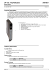
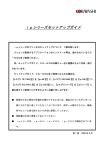
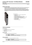
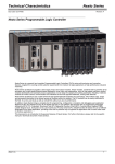
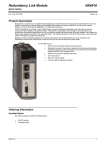
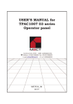
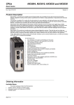
8 AI RTD Module NX6020 Nexto Series Doc.Code: CE114304 Revision: B Product Description Nexto Series is a powerful and complete Programmable Logic Controller (PLC) with unique and innovative features. Due to its flexibility, smart design, enhanced diagnostics capabilities and modular architecture, Nexto can be used for control systems from medium to high-end large applications. Due to its compact size, high density of points per module and superior performance capacity, Nexto can also be used for small automation systems with high performance requirements as industrial machines and manufacture applications. Nexto Series presents a wide range of I/O modules which were designed to fit requirements in different kinds of applications. NX6020 module allows the reading of the temperature sensors of RTD type (resistance temperature detectors), supporting a wide variety of sensors and resistance bands as well. The module has eight inputs which are individually configurable, allowing the use of temperature scales either in Celsius or Fahrenheit and configurable filters which help in the implementation of de industrial automation systems and processes control. Finally, Nexto Series has some innovative features for diagnosis and maintenance, such as Electronic Tag on Display, Easy Plug System and One Touch Diag. Its main features are: 8 RTD analog inputs and resistance in a single width module Support for different types of RTD sensors: Pt100, Pt200, Pt500, Pt1000, Ni100, Ni120, Ni200, Ni500, Ni1000 and Cu10 Support for multiple resistance range: 0 to 400 Ω and 0 to 4000 Ω Individual configuration per input Software configurable filters Galvanic isolation between inputs and internal logic Protection against surge voltage Support for hot swap Under and over range diagnostics Display for module diagnostics and input state indication Easy Plug System One Touch Diag Electronic Tag on Display Ordering Information Included Items The product package contains the following items: NX6020 module 20-terminal connector with wire holder Installation guide Product Code The following code should be used to purchase the product: Code NX6020 Altus S. A. Description 8 AI RTD Module 1 8 AI RTD Module NX6020 Nexto Series Doc.Code: CE114304 Revision: B Related Products The following product must be purchased separately when necessay: Code Description NX9403 20-terminal connector with wire holder Innovative Features Nexto Series brings to the user several innovations in utilization, supervision and system maintenance. These features were developed focusing on a new experience in industrial automation. The list below shows some new features that the user will find. Easy Plug System: Nexto Series has an exclusive method to plug and unplug I/O connectors. The connectors can be easily removed with a single movement and with no special tools. In order to plug the connector back to the module, the frontal cover assists the installation procedure, fitting the connector to the module. One Touch Diag™: One Touch Diag is an exclusive feature that Nexto Series brings to PLCs. With this new concept, the user can check diagnostic information of any module present in the system directly on CPU’s graphic display with one single press in the diagnostic switch of the respective module. OTD is a powerful diagnostic tool that can be used offline (without supervisor or programmer), reducing maintenance and commissioning times. ETD – Electronic Tag on Display: Another exclusive feature that Nexto Series brings to PLCs is the Electronic Tag on Display. This new functionality makes the process of checking the tag of any I/O terminal or module used in the system directly on the CPU’s graphic display. Along with this information, the user can check the description as well. This feature is extremely useful during maintenance and troubleshooting procedures. IF Product Design Award 2012: Nexto Series was the winner of iF Product Design Award 2012 in industry + skilled trades group. This award is recognized internationally as a seal of quality and excellence, considered the Oscars of the design in Europe. Altus S. A. 2 8 AI RTD Module NX6020 Nexto Series Doc.Code: CE114304 Revision: B Product Characteristics General Characteristics NX6020 Backplane rack occupation 1 slot Module type 8 analog inputs Input type Individually configurable inputs Resistances: 0 to 400 Ω and 0 to 4000 Ω Sensors RTD: Pt100, Pt200, Pt500, Pt1000, Ni100, Ni120, Ni200, Ni500, Ni1000 and Cu10 Data format 16 bits in two’s complement, justified to the left Converter resolution 24 bits monotonicity guaranteed, no missing codes Input state indication Yes One Touch Diag (OTD) Yes Electronic Tag on Display (ETD) Yes Status and diagnostic indication Display, web pages and CPU’s internal memory Hot swap support Yes Module protection Yes, protection against surge voltages Isolation Inputs to logic 1500 Vac / 1 minute Inputs to protective earth 1500 Vac / 1 minute Logic to protective earth 1500 Vac / 1 minute Current consumption from backplane rack 300 mA Maximum power dissipation 3W IP level IP 20 Operating temperature 0 to 60 °C Storage temperature -25 to 75 °C Operating and storage relative humidity 5 to 96 %, non-condensing Conformal coating Yes IEC 61131-2 CE, Electromagnetic Compatibility directives (EMC) and Lowvoltage devices (Low-Voltage Directive – LVD) Standards Module dimensions (W x H x D) 18.00 x 114.62 x 117.46 mm Package dimensions (W x H x D) 25.00 x 122.00 x 147.00 mm Net weight 200 g Gross weight 250 g Notes: Conformal coating: Conformal coating protects the electronic components inside the product from moisture, dust and other harsh elements to electronic circuits. Altus S. A. 3 8 AI RTD Module NX6020 Nexto Series Doc.Code: CE114304 Revision: B Temperature Mode Characteristics (RTD) NX6020 Precision (25 °C) 0..400 ±0.05% of full scale rating 0..4000 ±0.05% of full scale rating Pt (100, 200, 500, 1000) ±0.5 °C Ni (100, 120, 200, 500, 1000) ±0.5 °C Cu10 ±1 °C Precision (0 to 60 °C) 0..400 ±0.15% of full scale rating 0..4000 ±0.15% of full scale rating Pt (100, 200, 500, 1000) ±1.2 °C Ni (100, 120, 200, 500, 1000) ±1 °C Cu10 ±1.5 °C Measurement unit °C or °F Input impedance > 10 MΩ Connection types 2 and 3 wires Excitation current 1.02 mA Continuous maximum voltage ±15 Vdc Noise Suppression Filter Disabled, 50 Hz and 60 Hz Conversion time 50 Hz 82.5 ms / channel 60 Hz 69.ms / channel Disabled 12.5 ms / channel Maximum conversion time 50 Hz 660 ms 60 Hz 552 ms Disabled 100 ms Low pass filter time constant Disabled, 100 ms, 1 s and 10 s Noise suppression filter Temperature unit Configurable parameters Input types Connection types Digital filter Open input detection Yes, available in diagnostics Over range indication Yes Under range indication Yes Sensor cable maximum impedance 20 Ω per wire Notes: Noise suppression filter: The value of the selected filter in this parameter will be applied to all module reading inputs. Conversion time: Each module channel corresponds to an enabled input. Maximum conversion time: The conversion time shown in the table above refers to the total conversion time for the 8 channels according to the selected noise suppression filter. Open input detection: In this situation will be presented an over range indication and the read value presented will be the full scale rating selected. Altus S. A. 4 8 AI RTD Module NX6020 Nexto Series Doc.Code: CE114304 Revision: B Maximum impedance of the sensor cable: On a two-wire connection, the value read is the result of the sum of the sensor reading and resistance of each wire. In case of using this connection with large cables, the value read by the module will be affected by the effect of the resistance of the cable wires. On a three-wire connection, the error due to wire resistance is compensated by measuring the resistance value of one of the cable wires. Therefore, to enable a correct compensation is necessary for all the cable wires to have the same resistance. Over range indication: When the input selected is RTD reading type and the sensor input value is greater than the maximum value of full scale for the range selected, the symbolic variable will be enabled. In this condition, besides enabling the diagnostic variable, the module will set the value read to the maximum value of full scale configured for this channel. In case of resistance reading, the diagnostic becomes active when the input value read in the input is 1% greater than the maximum value of full scale configured for this channel. If the value read exceeds 5% of the maximum value of full scale, the module will set the reading variable of this channel to this value. Under range indication: This diagnostic becomes active when the input selected is RTD reading type and the value read in the channel is less than the minimum value of full scale for the selected range. E.g. for the PT100E (-200 a +850 °C) scale, the diagnostics variable will be enabled when the measured value is less than -200 °C. In this condition, besides enabling the diagnostic variable, the module will set the value read to the minimum value of full scale configured for this channel. For resistance reading scale this diagnostic is not available. The tables below show the functioning of over range and under range diagnostics according to the RTD sensor or applicable resistance scale. Sensors of Platinum type (Pt) = 0.00385 Diagnostics Sensors of Platinum type (Pt) = 0.003916 Sensors of Nickel type (Ni) Sensor of Copper type (Cu) Temperature Count Temperature Count Temperature Count Temperature Over range > 850 °C 8500 > 630 °C 8500 > 250 °C 2500 > 260 °C 2600 No diagnostics 850 to -200 °C 8500 to -2000 630 to -200 °C 8500 to -2000 250 to -60 °C 2500 to -600 260 to -200 °C 2600 to -2000 Under range < -200 °C -2000 < -200 °C -2000 < -60 °C -600 < -200 °C -2000 0 to 400 Ω Scale Diagnostics Over range 0 to 4000 Ω Scale Resistance Count Resistance > 420 Ω 4200 > 4200 Ω 4200 420 to 404.1 Ω 4200 to 4041 4200 to 4041 Ω 4200 to 4041 404 to 0 Ω 4040 to 0 4040 to 0 Ω 4040 to 0 No diagnostics Count Count The table below presents the types of configurable inputs supported by NX6020 module. Input type Temperature Coefficient () Measurement Band Count Resolution Pt100E, Pt200E, Pt500E, Pt1000E 0.00385 -200 to 850 ºC -328 to 1562 °F -2000 to 8500 -3280 to 15620 0.1 °C 0.2 °F Pt100A, Pt200A, Pt500A, Pt1000A 0.003916 -200 to 630 ºC -328 to 1166 °F -2000 to 6300 -3280 to 11660 0.1 °C 0.2 °F Ni100, Ni200, Ni500, Ni1000 0.00618 -60 to 250 °C -76 to 482 °F -600 to 2500 -760 to 4820 0.1 °C 0.2 °F Ni120 0.00672 -60 to 250 ºC -76 ºF to 482 ºF -600 to 2500 -760 to 4820 0.1 °C 0.2 °F Cu10 0.00427 -200 to 260 ºC -328 ºF to 500 ºF -2000 to 2600 -3280 to 5000 0.1 °C 0.2 °F 400 Ω - 0 to 400 Ω 0 to 4000 0.1 Ω 4000 Ω - 0 to 4000 Ω 0 to 4000 1Ω Note: Temperature Coefficient (): For the Platinum type sensors (Pt100, Pt200, Pt500 and Pt1000) there are two supported coefficients. For other types of sensors there is only one associated temperature coefficient. In the Module Parameters the possible settings per channel can be found. Altus S. A. 5 8 AI RTD Module NX6020 Nexto Series Doc.Code: CE114304 Revision: B Installation Electrical Installation The figure below shows an example where some inputs of NX6020 module are used: input 00, input 02, input 03 and input 06. Each one of these inputs presents a different type of connection, according to the following. Diagram Notes: 1 – The diagram above has the representation a set of terminal blocks where each symbol represents a different kind of terminal block: represnts a standard feed-through terminal block, represents a grounding terminal block, represents a feed-through terminal block with connection to other terminal block and represents a fuse terminal block. 2 – Input 00 shows an example of a 2-wire connection. In this case only one of the ends of the sensor grounding shield in the field and the cable used to connect the module NX6020 to the terminals of the electric panel are being connected to the earth terminal of the electric panel. In this type of connection, the other end of each cable must not be connected to other grounding point. 3 – Inputs 02 and 03 show examples of 3-wire connection, where the compensation wire of the sensors are connected to the NX6020 module at one single point (C2), which refers to the ports 02 and 03. 4 – Input 06 shows an example of a 3-wire connection, where the central point of grounding is done is the field. One end of the sensor grid in the field is connected to field grounding point and the other end is connected to the electric panel terminal board. The cable grid used to connect the electric panel terminal board to the NX6020 module terminals is connected in only one of its ends (which are connected to the electric panel terminal board). 5 – The use of RA, RB and C signal depends on the number of wires used in the sensor connection. 6 – The module power supply is derived from the connection to the backplane rack, not requiring external connections. 7 – The NX6020 module is grounded through the backplane rack . The following table shows the description of each connector terminal: Altus S. A. 6 8 AI RTD Module NX6020 Nexto Series Doc.Code: CE114304 Terminal 1A 2A 3A 4A 5A 6A 7A 8A 9A 10A 11A 12A 13A 14A 15A 16A 17A 18A 19A 20A Revision: B Input 00 Common 01 02 Common 03 04 Common 05 06 Common 07 Description Positive signal RTD (excitation current for 2/3 wire sensor) RTD negative Compensation for 3-wire sensor RTD positive signal (excitation current for sensor 2/3 wire) RTD negative RTD positive signal (excitation current for sensor 2/3 wire) RTD negative Compensation for 3-wire sensor RTD positive signal (excitation current for sensor 2/3 wire) RTD negative signal RTD positive (excitation current for sensor 2/3 wire) RTD negative signal Compensation for 3-wire sensor RTD positive signal (excitation current for sensor 2/3 wire) RTD negative signal RTD positive (excitation current for sensor 2/3 wire) RTD negative signal Compensation for 3-wire sensor RTD positive signal (excitation current for sensor 2/3 wire) RTD negative signal Note: NX6020 module has no grounding terminals through the connector. The grounding is done through the terminal board or in the field sensor as described in the Electrical Installation. Mechanical Assembly The mechanical and electrical mounting and the connector pin insertion and removing for single hardware width I/O modules are described at Nexto Series User Manual – MU214600. Compatibility with Other Products The following table brings information regarding the compatibility between NX6020 module and the Nexto Series MasterTool IEC XE programming tool. Nexto Series CPUs Compatible Software Version Version NX6020 Revision Version MasterTool IEC XE 1.0.0.0 AA 1.4.0.0 or higher 2.00 or higher Note: Product revision: If the software is upgraded in the field the product reviewing indicated on the label will no longer match the actual review of the product. Altus S. A. 7 8 AI RTD Module NX6020 Nexto Series Doc.Code: CE114304 Revision: B Physical Dimensions Nexto Series User Manual - MU214600 should be consulted for general measurement of installation panel. Dimensions in mm. Altus S. A. 8 8 AI RTD Module NX6020 Nexto Series Doc.Code: CE114304 Revision: B Configuration NX6020 module was developed to be used with Nexto Series products. All Nexto Series products are configured in MasterTool IEC XE. All configuration data of a given module can be accessed through a double click in it on the Graphical Editor. Process Data Process Data are the variables that are used to access the NX6020 module. The list below describes all variables delivered by NX6020 module. The process data of the module, when inserted in a PROFIBUS network, can be accessed through variables. The table below presents the variables organizational structure in the UCP memory. Besides these data, this module also provides a set of variables containing information related to diagnostics which are also described in this document. Variable Size Process Data Description Type Update %IB(n) WORD AI 00 Analog Input 00 INT (Reading) Always %IB(n+2) WORD AI 01 Analog Input 01 INT (Reading) Always %IB(n+4) WORD AI 02 Analog Input 02 INT (Reading) Always %IB(n+6) WORD AI 03 Analog Input 03 INT (Reading) Always %IB(n+8) WORD AI 04 Analog Input 04 INT (Reading) Always %IB(n+10) WORD AI 05 Analog Input 05 INT (Reading) Always %IB(n+12) WORD AI 06 Analog Input 06 INT (Reading) Always %IB(n+14) WORD AI 07 Analog Input 07 INT (Reading) Always Note: Update: The field “Update” indicates if the respective process data is updated by CPU and NX6020 module by default. When defined as “Always”, it means that the process data is always updated. When defined as “Selectable”, it means that the user can select if the respective process data will be updated or not. All these process data are exchanged between CPU and NX6020 module through the bus, to improve CPU performance. It is recommended to update only the process data that will be used in the application. Module Parameters Altus S. A. Name Description Standard Value Options Configuration Noise Suppression Filter Enables or disables the Noise Suppression Filter in the frequencies of 50 Hz or 60 Hz 60 Hz 50 Hz 60 Hz Disabled Per module Temperature Unit Selects the temperature unit Degrees Celsius Degrees Celsius Degrees Fahrenheit Per module Per channel Input Type Configuration of the input type Non Configured Non configured 400 Ω 4000 Ω Pt100A Pt100E Pt200A Pt200E Pt500A Pt500E Pt1000A Pt1000E Ni100 Ni120 Ni200 Ni500 Ni1000 Cu10 Connection Time Configures the connection time Two Wires Two wires Three wires Per channel Digital Filter Configures the time or Disabled Disabled Per channel 9 8 AI RTD Module NX6020 Nexto Series Doc.Code: CE114304 Revision: B disables the low pass filter 100 ms 1s 10 s Notes: Configuration: Indicates whether certain functionality of the module is related to an entire module configuration (per module), or if the functionality is related to a single input (per channel). Noise Suppression Filter: This parameter is used to select the frequency of the noise suppression filter which is applied to all NX6020 module inputs. This filter rejects a particular frequency in the analog signal measurements. For each frequency configured there is an associated conversion time which must be regarded during the development of an application in the channels reading. For further information on the conversion time according to the selected filter, see the Temperature Mode Characteristics (RTD). Input Types: Exclusively for the RTD sensors of Platinum type (Pt100, Pt200, Pt500 and Pt1000), this module supports two temperature coefficients (), which are different from each other by its last character. For the option which ends with A the is 0.003916 and for the option with E is 0.00385. For information on the values of the temperature coefficients used for each type of RTD sensor, see the Temperature Mode Characteristics (RTD). Digital Filter: This parameter enables or disables, per channel, of a first order low pass digital with time constant of 100 ms, 1 s or 10 s. If there is a signal in a channel with the digital filter enabled and a hot swap is performed in the module, the channel will start with zero until it reaches the input value, according to the selected time constant, in a dynamic way. Module Usage RTD Analog Input Read NX6020 module has one variable for each input. The parameters of minimum value and maximum value are automatically configured according to the selected RTD type. NX6020 module has one variable for each input, which will be presented in the temperature scale defined in the Measurement Unit, where the value is multiplied for 10. Thus, a 25 ºC temperature, for example, is read as 250. Maintenance Altus recommends that all modules’ connections should be checked and any dust or any kind of dirt in the module’s enclosure should be removed at least every 6 months. Nexto Series CPUs offers many important features to assist users during maintenance: Electronic Tag on Display, One Touch Diag, status and diagnostics indicators, web page with complete status and diagnostics list and status and diagnostics mapped to internal memory. Electronic Tag on Display and One Touch Diag Electronic Tag on Display and One Touch Diag are important features that provide to the user the option to check the tag, description and diagnostics related to a given module directly on the CPU display. Electronic Tag on Display and One Touch Diag are easy-to-use features. To check the tag and diagnostics of a given module, it’s required only one short press (shorter than 1 s) on its diagnostic switch. After pressing once, CPU will start to scroll tag information and diagnostic information of the module. To access the respective module description just long press (longer than 1 s) the diagnostics switch of the respective module. More information about Electronic Tag on Display can be found at Nexto Series CPUs User Manual – MU214605. Status and Diagnostics Indicators All Nexto slave modules have a display with the following symbols: D, E, 0, 1 and numerical characters. The states of the symbols D, E, 0, 1 are common for all Nexto Series slave modules. These states can be consulted in the table below. Altus S. A. 10 8 AI RTD Module NX6020 Nexto Series Doc.Code: CE114304 Revision: B D and E States D E Description Cause Solution Priority Module off, external power supply fail or hardware fail Check if the module is completely connected to the backplane rack and if the backplane rack is supplied by an external power supply - Off Off Display fail or module off On Off Normal use - - 9 (Lower) Off Active Diagnostics There is at least one active diagnostic related to the module Check what the active diagnostic is 8 Blinking 2x Off CPU in STOP mode. If the module is in a Remote PROFIBUS, Master is in Clear state. CPU in STOP mode Check if CPU is in RUN mode or if PROFIBUS Master is in OPERATE mode. More information can be found on CPU’s or PROFIBUS Master’s documentation 7 Blinking 3x Off Reserved - - 6 5 Blinking 1x Blinking 4x Off Non-fatal hardware fault Hardware fault The module remains with its main functionality. For fail correction please contact Altus Technical Support Off Blinking 1x Parameterization error The module isn’t parameterized or didn’t receive the parameterization Check if the module parametrización is ok 4 Check if the module is completely connected to the backplane rack Check if CPU is in RUN mode or if PROFIBUS head is Active. 3 Off Blinking 2x Loss of master Loss of communication between module and CPU or module and PROFIBUS head. Off Blinking 3x Module without calibration NX6020 isn´t calibrated or there was an error with the calibrated value In this case, the module should return to the manufacturer 2 Off Blinking 4x Fatal hardware fault Hardware fault Contact Altus Technical Support in case of fatal hardware fault 1 (Higher) 0, 1 and Numerical Characters The segments 0 and 1 are used to group the numerical characters used for inputs and outputs. In NX6020 module's case, the characters that are placed at the right side of character 0 represent the inputs from 00 a 07, where character 0 represents the input 00 and character 7 represents the input 07. The characters that are placed at the right side of character 1 and the segment 1 itself are not used in NX6020 module. The figure below shows the relationship between the numerical characters and the respective inputs. Altus S. A. 11 8 AI RTD Module NX6020 Nexto Series Doc.Code: CE114304 Revision: B Web Pages with Complete Status and Diagnostics List Another way to access diagnostics information on Nexto Series is via web pages. Nexto Series CPU’s has an embedded web page server that provides all Nexto status and diagnostics information, which can be accessed using a simple browser. More information about web page with complete status and diagnostics list can be found at Nexto Series CPUs User Manual – MU214605. Diagnostics Mapped to Variables All NX6020 modules’ diagnostics can be accessed through variables that can be handled by the user application or even forwarded to a supervisory system using a communication channel. There are two different ways to access diagnostics in the user application: using symbolic variables with AT directive or addressing memory. Altus recommends the use of symbolic variables for diagnostic accessing. The table below shows all available diagnostics for NX6020 module and their respective memory address, description, symbolic variable and string that will be shown on the CPU graphical display and web. Direct Representation Variable Variable Diagnostic Message Bit Symbolic Variable DG_modulename.tGeneral. INPUT 00 W/ DIAG 0 bActiveDiagnosticsInput00 TRUE – Input 00 has active diagnostics - FALSE – Input 00 has no active diagnostics INPUT 01 W/ DIAG TRUE – Input 01 has active diagnostics 1 bActiveDiagnosticsInput01 - FALSE – Input 01 has no active diagnostics INPUT 02 W/ DIAG TRUE – Input 02 has active diagnostics 2 bActiveDiagnosticsInput02 - FALSE – Input 02 has no active diagnostics INPUT 03 W/ DIAG TRUE – Input 03 has active diagnostics %QB(n) 3 bActiveDiagnosticsInput03 - FALSE – Input 03 has no active diagnostics INPUT 04 W/ DIAG TRUE – Input 04 has active diagnostics 4 bActiveDiagnosticsInput04 - FALSE – Input 04 has no active diagnostics INPUT 05 W/ DIAG TRUE – Input 05 has active diagnostics 5 bActiveDiagnosticsInput05 - Altus S. A. Description FALSE – Input 05 has no active diagnostics PROFIBUS Message Code - - -- - - - 12 8 AI RTD Module NX6020 Nexto Series Doc.Code: CE114304 Revision: B INPUT 06 W/ DIAG 6 bActiveDiagnosticsInput06 INPUT 07 W/ DIAG 7 bActiveDiagnosticsInput07 0 TRUE – Input 07 has active diagnostics FALSE – Input 07 has no active diagnostics MODULE W/ DIAGNOSTICS TRUE – Module has active diagnostics MODULE W/ FATAL ERROR bActiveDiagnostics bFatalError CONFIG. MISMATCH 2 bConfigMismatch - %QB(n+1) WATCHDOG ERROR 3 FALSE – Module has no active diagnostics TRUE – Fatal error bWatchdogError TRUE – Parameterization error FALSE – Parameterization ok TRUE – Watchdog has been detected - FALSE – No watchdog OTD SWITCH ERROR TRUE – Module has diagnostic switch failure 4 bOTDSwitchError CALIBRATION ERROR bCalibrationError - - 25 FALSE – Diagnostic switch ok TRUE – Module without calibration 26 27 28 29 FALSE – Module calibrated 6..7 - FALSE – No fatal error - 5 FALSE – Input 06 has no active diagnostics - - 1 TRUE – Input 06 has active diagnostics Reserved Detailed Diagnostics Direct Representation Variable Variable Bit %QB(n+2+ XX*2) 0..7 0 Diagnostic Message Symbolic Variable DG_ modulename.tDetailed.tAnal ogInput_XX %QB(n+2+2 *XX+1) OVER RANGE bOverRange UNDER RANGE 2 4..7 TRUE – Input data are over range 24 FALSE – Input data are ok bUnderRange TRUE – Input data are under range 25 FALSE – Input data are ok - 3 PROFIBUS Message Code Reserved 1 Description Reserved - bInputNotEnable TRUE – Input is not enabled FALSE – Input is enabled 26 Reserved Notes: Direct Representation Value: “n” is the address defined in the field %Q Start Address of Diagnostic Area on the NX6020 module’s configuration screen – Modules Parameters tab in the MasterTool IEC XE, “XX” is the channel of analog input. Some symbolic variables serve to access diagnostics. These diagnostics are stored into the addressing memory, then the AT directive is used to map the symbolic variables in the addressing memory. The AT directive is a reserved word in the MasterTool IEC XE, that uses this directive to declares the diagnostics automatically on a symbolic variable. All symbolic variables declared automatically can be found in the diagnostics object. Altus S. A. 13 8 AI RTD Module NX6020 Nexto Series Doc.Code: CE114304 Revision: B Manuals For further technical details, configuration, installation and programing of Nexto Series CPUs User Manual - MU214605 should be consulted. The table below is only a guide of some relevant documents that can be useful during the use, maintenance, and programming of NX6020 modules. The complete and updated table containing all documents of Nexto Series can be found at Nexto Series User Manual – MU214600. Altus S. A. Document Code Description Language CE114000 CT114000 CS114000 Nexto Series – Technical Characteristics Série Nexto – Características Técnicas Serie Nexto – Especificaciones y Configuraciones English Portuguese Spanish MU214600 MU214000 MU214300 Nexto Series User Manual Manual de Utilização Série Nexto Manual Del Usuario Serie Nexto English Portuguese Spanish MU299609 MU299048 MU299800 MasterTool IEC XE User Manual Manual de Utilização MasterTool IEC XE Manual Del Usuário MasterTool IEC XE English Portuguese Spanish 14