1
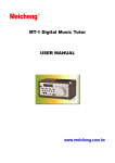
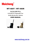
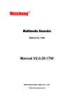
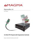
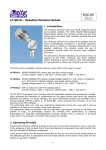
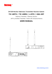
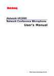
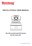
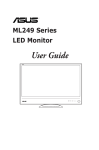
Meicheng
®
KPS-12SD
SYSTEM POWER SUPPLY CONTROLLER
USER MANUAL
www.meicheng.com.tw
TABLE OF CONTENTS
Safety And Service Instructions…… . . . . . . . . . . . . . . . . . . . . . . . . . . .. . . . . 1
Features . . . . . . . . . . . . . . . ……………………. . . . . . . . . . . . . . . . . . . .. . . . . . . 2
Parts and Functions . .. . . . . .. . . . . . . . .. . . . . . . . . . . . . . . . . . . . . . .. . . . . . 3
Front Panel . . . . . . . .... . . . . . . . . . . . . . . ... ……….. . . . . . . . . . . .. .. . . . . . . . . . 3
Rear Panel. . . . . . . . . . . .. . . . . . . . . . . . … . . . . . . . . . . . . . . . . . .. . . . . . . . . . . . .3
Operation. . . . . . . . . . . . . . . . . . . . . . . . . . . . . . . . . . . . . . . . . . . . . . . . . . . . . . . . . 4
Installation And Connections . . . . . . . . . . . . . . . . . . . . . . . . . . . . . . . . . . . . . . .6
Specifications . . . . . . . . . . . . . . . . . . . . . . . . . … . . . . . . . . . . . . . . . . . . . . . . . . .. 7
SAFETY INSTRUCTIONS
1. Safety Precautions
● Be sure to read the instructions in this section carefully before use.
● Make sure to observe the instructions in this manual as the conventions of safety
symbols and messages regarded as very important precautions are included.
● We also recommend you keep this instruction handy for future reference.
2. Safety Symbol and Message Conventions
Safety symbols and messages described below are used in this manual to prevent
bodily injury and property damage which could result from mishandling.
WARNING Indicates a potentially hazardous situation which could result in death or
serious personal injury if mishandled.
When Installing the Unit
●Do not expose the unit to rain or an environment where it may be splashed by water
or other liquids, as doing so may result in fire or electric shock.
●Only use with the voltage specified on the unit. Using a higher voltage which is
specified may result in fire or electric shock.
●Do not cut, kink, otherwise damage nor modify the power supply cord. In addition,
avoid the power cord closing to heaters, and never place heavy objects including
the unit itself on the power cord, as doing so may result in fire or electric shock.
●Avoid installing or mounting the unit in unstable locations. Doing so may result in
the unit falling down and causing personal injury or property damage.
●Do not block the upper panel ventilation slots. Doing so may cause heat to build up
inside the unit and result in fire. Avoid installing the unit in humid, dusty locations,
or exposed to the sunlight directly. Keep the heaters, sooty smoke or steam away.
When Use It
●If you encounter the following irregularity during use, immediately switch off the
power. Don’t operate the unit in this condition to avoid fire or electric shock.
If you detect smoke or strange smell
If water or any metallic object, gets into the unit
If the unit falls, or the unit case breaks down
If the power supply cord is damaged (exposure of the core, disconnection, etc.)
If it is malfunctioning (no sounds)
●Do not insert nor drop metallic objects or flammable materials in the ventilation
slots, that may result in fire or electric shock. Do not touch a plug or antenna during
thunder and lightning that may result in electric shock.
●Do not place heavy objects on the units, that may cause it to fall or break which
may result in personal injury or property damage. In addition the object itself may
fall off and cause injury and/or damage.
CAUTION Indicates a potentially hazardous situation which could result in
moderate or minor personal, property damage if mishandled.
KPS-12SD System Power Supply Controller
Features
z 40amp rating, with circuit breaker. Voltmeter to display incoming mains
voltage. Good-sized connection terminal equipped with protective shield to
guaranty the security.
z 12-channel output, each with 10amp, uses all-purpose outlets for different
plugs.
z The KPS-12SD offers all basic power conditioning features. It provides
varistor spike and surge protection across all three modes (line to neutral,
line to ground, and neutral to ground), specialized 40amp multi-stage EMI
filter is used to purify system power. The filter works to prevent noise from
fluorescent lights, certain dimmers, radio transmitters, and similar sources of
“electronic pollution” from leaking from the AC line to audio, video, or
computer circuits. Ensuring the system operation stability and optimal
performance.
z Intelligent design with MCU controlled, and with multiple control modes
and interfaces:
Direct control modes
Key switch control
Standby key START ON-OFF sequence control
IR remote controller
External control modes Emergency/External DC24V control in
REM IN (TTL) DC5V control in
Standard RS232 serial interface (IN/OUT)
z
z
z
z
z
Meeting all kinds of system configuration requirements.
Flexible functional PC control software is supplied for system control. It can
be programmed and controlled by PC through RS232 interface.
IR remote controller can be used to switch on/off any channel output.
Remote controller can be also used to multiple operation modes:
A. It can set any channel as bypass mode.
B. The delay interval (the time between the sequential turn-on or turn-off
outlets 1 and 2, or 2 and 3) can be adjusted to a maximum of 10 minutes.
Meeting special requirements of certain equipments (e.g. projector or
others).
Key Lock function to prevent accidental operation, and assist user
administration.
Mechanical Dimensions: 3UH, 19 inch W
Construction: black and silver anodized aluminum panels.
Parts and Functions
Front Panel
①40A Circuit Breaker
②AC Voltmeter
③Channel Power Status LED indicator
④LOCK Indicator
⑤Delay Interval Setting Indicator
SET ON indicates turn-on delay setting mode;
SET OFF indicates turn-off delay setting mode in reversed sequence.
OK indicates delay interval setting orders are being carried out.
⑥IR Sensor
⑦STANDBY is a shortcut control key, push to on, and push again to off.
⑧Key Switch turn the key clockwise to switch on and turn anticlockwise to
switch off.
Remote Control
①STANDBY
②1-12 Channel Control Keys.
Use each key to control the power output
when LOCK is off.
Also use control keys to set delay of each channel.
③SET ON (Delay)
④SET OFF (Delay)
⑤Delay Interval: 0.5 Second~600 Second
⑥LOCK key:
It turn on/off the “LOCK” indicator in the front panel.
When “LOCK” lights up, the “standby” control key is out of use.
⑦ALL: All channels are selected.
⑧ESC: Use this key to exit delay setting, and SET
ON or SET OFF light off.
Rear Panel
REM IN
DC5V
①EMG/EXT (DC 12V~24V): Emergency/External start control.
②REM IN (DC 5V) for IR remote control input
③RS232 IN
④RS232 OUT
⑤1~12 OUTLETS (Channel 1 ~12)
⑥Mains Connection Terminal
⑦Wiring Terminal Protective Shield
Operation
1. Mains Connection
A. Use 2.5, 4.0, or 6.0 RV/RVV/BV/BVV copper wires according to power
specifications.
Note: Properly connect in through L(live), N(neutral) and Ground wire.
B. When the circuit breaker is on, voltmeter indicates the AC voltage.
2. Control Operation
A. Ensure “LOCK” on the front panel lights off.
Press the STANDBY key on front Panel, to turn on/off power. During the
turning on/off process, press STANDBY to finish operation.
Note: “press” in this operation means “press and hold the key for seconds”
(When the key is effectively on, there is change in LOCK status).
B. Use 1-12 Channel Control Key to control the power on/off of each channel
when “LOCK” is off.
C. Use Key Switch to turn on/off power, independent of LOCK status.
Note: Remote Control can not control “LOCK” when Key Switch is on.
3. Set-up Operation:
Use Remote Control to set up the system after power is turned off and “LOCK” is
lit.
A. Set on/off BYPASS:
Set on any channel as BYPASS, then the channel outlet being switched on.
Equipments incorporating clocks or timers such as MTC timer controller,
VCR’s, or equipment that must respond to wireless remote actuation should
use the outlets.
Sample 1: Set on Channel 1 and Channel 2 as BYPASS.
Press Set on to light on. Press “1” key on, then press BY, and OK
Indicator lights up for 1 second, showing the setting is confirmed.
Press “2” key on, then press BY, and OK Indicator lights up for 1
second, showing the setting is accomplished. Thus Channel 1 and
Channel 2 become BYPASS, and both channels light up constantly.
Sample 2: Set Channel 2 off BYPASS.
Press Set off to light on. Press “2” key, then press BY, channel 2
turn off, and OK Indicator lights on for 1 second, showing the
setting is accomplished. Thus Channel 2 cancel BYPASS mode.
B. Set the delay interval between adjacent channels of power up or down:
The delay time is factory preset as 1 second between adjacent channels. It can
be adjusted according to the user’s requirements.
Sample 1: To set the turn-on delay interval from Channel 1 to Channel 2 at
0.5 second.
Press “Set on”, and the “Set on” LED on Front Panel lights up.
Press “2” key and the “2” LED on Front Panel lights up, then press
0.5s key, and OK Indicator lights up for 1 second, showing the
setting is confirmed.
Sample 2: Set the delay time of sequential turn off from Channel 3 to
Channel 2 is 300 second. Press “Set off” key and the “Set off” LED
on Front Panel lights up. Press “2” key, then press “300s” key, and
“OK” Indicator lights up for 1 second, showing the setting is
accomplished.
Sample 3: Set the delay time of sequential turn on from Channel 1 to Channel
2 is 0.5 second. Press “Set on” and the “Set on” LED on Front Panel
lights up. Press “ALL” key, then all the indicators of 12 channel
light up, press 0.5s key, and OK Indicator lights up for 1 second,
showing the setting is confirmed.
Note: Press ESC key to exit setting mode. If you do no operation after setting,
it will exit automatically a little time later.
C. Factory Preset Recovery:
The delay time is factory preset as 1 second between adjacent channels. Users
can return to factory preset according to needs.
When LOCK indicator is on, hold ESC key till all “Set on”, “OK”, “Set off”
indicators flash simultaneously, then recovery is accomplished.
4. External Controls:
Standard models have a variety of external control connectors, controlled by
external equipments.
A. EMG/EXT connection terminal
It’s used for emergency or external control needs. When the control signal
coming, the equipment will power up quickly (0.5 seconds delay). The
control signal is within the range of DC12V~24V, polarity free, insulated
through light coupling.
B. REM IN provides a common external TTL control mode, which is
conveniently embedded in central control systems. DC5V for IR Remote
Control input.
C. RS232 standard serial interface provides an open platform to control this
equipment more flexibly. Connected computers can operate, control, program,
and set 1 or more KPS-12SD. They meet the requirements of complex and
diverse systems.
Installation and Connection
The equipment is 19 inch 3UH standard rack mounted cabinet.
Synchronous control and connection of multiple power supplies
The first set is the host
Mains input
synchronizing controlled by the host
Mains input
Note:
It applies especially to multiple power supplies in one system. Synchronous
control of dependent power supplies can be realized both in direct control and
REM external control modes of host power supply.
PC Control Connection
1. Single system control
M ain s inp ut
PC
Main s inp ut
2. Multi- system control
Sub-system 1 p owe r control
R s2 32 t o R S 48 5 co nv e rte r
Main s inp ut
Sub-system 2 p owe r control
R s2 32 t o R S 48 5 co nv e rte r
R s2 32 t o R S 48 5 co nv e rte r
M ain s inp ut
C o n tro l ce n tre P C
Sub-system N p owe r co ntrol
R s2 32 t o R S 48 5 co nv e rte r
Main s inp ut
Control System Connection
1
R EM I N
M ain s inp ut
Control System
I/O co ntro l port
2
R s2 32 t o R S 48 5 co nv e rte r
M ain s inp ut
Contr ol System
RS48 5
Specifications
Mains
Overall capacity
Output
Panel control
External control
Conditioning filter
Dimension
Weight
Accessories
AC 100 - 240V 50-60Hz
40A
Channel 1~12, 10A Universal Outlets
STANDBY key control (“ LOCK” indicator is off)
Key Switch turn on and turn off
IR remote controller for single channel controlling
and start up/down
DC 12~24V quickly start up control for emergency
DC 5V REM IN for remote control
RS 232 serial port for PC or other system controller
RFI filter to reduce conductive noise.
Suppress power switching noise,
continuous or fitful pulse interference and no leakage to
ground.
Work Current: 40 amp
Leakage Current < 0.5 mA
Compliance to Europe CISPR,
USA FCC standards
482 X 354 X 132 mm
6 kg
IR remote controller, user’s manual, warranty card,
keys of key switch
Meicheng®
MEI CHENG AUDIO VIDEO CO., LTD
Address: 13F, NO.2, Jian Ba Road, Chung Ho City, Taipei Hsien 235, TAIWAN
Tel: +886(2) 2585 3869,
Website: www.meicheng.com.tw
Fax: +886(2) 2593 6672
Email:[email protected]