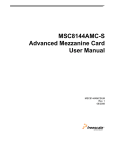
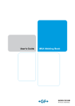
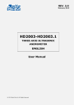
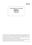
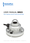
1
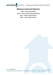
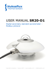
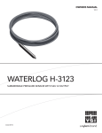
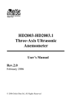
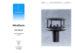
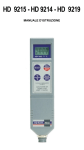
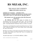
ENGLISH
LP SD18 – Sunshine Duration Sensor
Rev. 1.2
18/03/2014
1 Introduction
The Sunshine Duration sensor LP SD18 measures status
and sunshine duration. The WMO (World Meteorological
Organization) defines the sunshine duration as the time
during which the direct solar radiation exceeds the level
of 120 W/m2.
The LP SD18 performs the measure of radiation with an
array of photodiodes arranged in a particular geometry
which allows to obtain an accurate measurement in any
weather conditions. This solution avoids the use of
mechanical moving parts and ensures high reliability
over time.
The instrument, besides indicating the presence of sun as
required by the WMO, measures also direct radiation
(SRD), therefore it can be used as a low cost alternative
to a pyrheliometer, which use is bound to a solar tracker.
The instrument is available in three versions, which differ in the type of output:
LP SD18.1 RS485 MODBUS-RTU output and volt-free contact output
(contact closed = SRD ≥ 120 W/m2, contact open = SRD < 120 W/m2)
LP SD18.2 RS485 MODBUS-RTU output, analog voltage output 0…1 Vdc, which corresponds
to 0…2000 W/m2 of direct radiation, and digital output voltage
(digital voltage output: 1V = SRD ≥ 120 W/m2, 0V = SRD < 120 W/m2)
LP SD18.3 SDI-12 output and volt-free contact output
(contact closed = SRD ≥ 120 W/m2, contact open = SRD < 120 W/m2)
The LP SD18 is equipped with a heating element separately powered and galvanically isolated,
which prevents the formation of condensation on the glass surface onto which the sensitive
elements are placed. For harsh climates, the above-mentioned versions are available with a
second heating element (option R, LP SD18.xR), which prevents the formation of ice and
prevents snow from settling.
The instrument does not need any positioning adjustment during the year and it can be
installed on a mast or on a proper fixing base (optional).
The application fields are multiple: from the agronomy (agricultural science) to the study the
growth of crops, to photovoltaic systems for verifying their performance, to building
automations for automatic opening/closing of blinds, shutters and, in general, to all those
areas where it is necessary to monitor the presence of sunlight.
2 Operating Principle
The Sunshine Duration LPSD18 is based on the use of 16 sensors arranged in such a way that,
in the presence of sun, at least one of the photo-detectors is exposed to sun light directly from
the sun (besides the diffusion component).
Those sensors which are not directly illuminated by the sun are used for the measurement of
the diffused light that is subtracted from the measurement of the sensor which sees the sun
directly to get direct radiation.
-1-
The cylindrical glass protects the sensors and the internal circuits of the instrument from the
weather and at the same time provides an excellent transparency to sunlight.
In order to avoid the formation of condensation inside the instrument, in addition to the
heating element, the LPSD18 is supplied with a cartridge that must be loaded with desiccant
material in colloidal silica (Silica-gel).
3 Technical specifications
Sensitive elements
16 Silicon photodiodes
Spectral range
360…1100 nm
Direct radiation SRD measuring range
0…2000 W/m2
Accuracy of the measurement of direct
radiation
Better than 90% on the monthly total
Accuracy of the measurement of the
sunshine duration sensor
Better than 90% on the monthly total
Response time
<1 second
Threshold value
120 W/m2
Sunshine duration resolution
1 sec
Power supply
Consumption
7…30 Vdc
5mA @ 12V
Heating system
Anti-condensation device consumption
Antifreeze device consumption
12…15 Vdc
1W @ 12V
5W @ 12V
Internal temperature
Measuring range
Accuracy
-40…+80 °C
± 0.5 °C
Operating temperature
-40…+80 °C
Weight
0.9 kg
Protection degree
IP66
Outputs
LP SD18.1
ON for internal Temp. < 6 °C,
OFF for internal Temp > 10 °C
• RS485 MODBUS-RTU
• Galvanically isolated contact
closed = SRD ≥ 120 W/m2
open = SRD < 120 W/m2
LP SD18.2
• RS485 MODBUS-RTU
• Analog output 0…1V (0…2000 W/m2)
• Digital output 0…1V
1V = SRD ≥ 120 W/m2
0V = SRD < 120 W/m2
LP SD18.3
• SDI-12
• Galvanically isolated contact
closed = SRD ≥ 120 W/m2
open = SRD < 120 W/m2
-2-
4 Preparation of the sunshine duration sensor
Before installing the instrument, refill the cartridge containing silica gel desiccant crystals.
During loading, avoid wetting or touching the material with the hands as it loses the power
desiccant.
The operations to be performed in a dry place (as far as possible) are the following:
1- unscrew the cartridge containing the silica gel by using a coin
2- remove the cartridge perforated cap
3- open the envelope (supplied with the sunshine duration sensor) containing the silica-gel
4- fill the cartridge with the silica-gel
5- close the cartridge with its own cap, by making sure the O-ring seal is correctly located
6- screw the cartridge to the body of the sunshine duration sensor by using a coin
7- check that the cartridge is properly screwed (otherwise the duration of the drying
capacity of the silica-gel is strongly reduced)
Fig. 1 briefly illustrates the operations necessary for filling the cartridge with the silica-gel.
LP SG
Silica-gel
cartridge
Sealed sachet of
silica-gel crystals
Perforated
cap
LP G
B
A
Closing the
cartridge
Filling
D
C
Fig. 1: filling the cartridge with the silica-gel
-3-
5 Installation of the sunshine duration sensor
The sunshine duration sensor should be installed in a place easy to be reached for the periodical
cleaning of the glass and the maintenance. At the same time, it should be avoided that buildings,
trees or obstructions of any kind exceed the horizontal plane on which the sunshine duration is
placed. It is acceptable to choose a location where obstacles in the path of the sun from sunrise
to sunset is less than 5° from the horizontal plane of the sunshine duration sensor. It should be
also checked that there are no reflective elements that may alter the measure.
The LP SD18 does not need any positioning adjustment during the year.
Three installation methods are possible:
• LP SD18.xB: basic version for installation on
a flat base by using the support included.
The Sunshine Duration Sensor has a fixed
inclination of 45° with respect to the
fixing plane.
Fig. 2: basic version LP SD18.xB
• LP SD18.xO: version for installation on the
base LP SD18.O. The base allows the
inclination of the sensor up to 80°
respect to the vertical, so to fit it to the
position of the sun to the latitude of the
place of installation. Two adjustable feet
and one fixed foot allow to put the sensor
on an horizontal plane.
Fig. 3: installation on the base LP SD18.O
• LP SD18.xV: version for installation on a
vertical Ø 40 mm mast by using the
LP SD18.V support. This support allows
to tilt the sensor up to 80° respect to the
vertical, so to fit it to the position of the
sun to the latitude of the place of
installation.
Fig. 4: installation on a vertical mast
by using the LP SD18.V support
-4-
Bubble level
Fixed installation on a flat base
Adjustable installation on a mast
with levelling device
Adjustable installation on a flat base
with levelling device
Fig. 5: details of the installation
-5-
Before orienting the Sunshine Duration Sensor to its final position, place it vertically and adjust
the base (for installation on a plane) or support (for installation on a ø 40 mm mast) feet so
that the level on the upper side of the instrument is perfectly levelled (Fig. 6).
Fig. 6: Levelling of the Sunshine Duration Sensor
Orient the Sunshine Duration Sensor so that the index of the graduated scale of the support
matches the value (90° - Latitude) and the top (where the spirit level is placed) is directed
towards the NORTH pole, if used in the northern hemisphere, or towards south, if used in the
southern hemisphere (Fig. 7).
Fig. 7: Orientation of the Sunshine Duration Sensor
-6-
The angle that instrument axis should make with respect to the ground is equal to the latitude
of the installation site, this way the axis of the instrument will be parallel to the earth axis
North-South (Fig. 8).
Fig. 8: Sunshine Duration Sensor parallel to the Earth axis
-7-
6 Electrical Connections
All the versions of the Sunshine Duration Sensor are equipped with an 8-pin M12 connector.
Upon request, cables with 8-pin M12 female connector with 5 or 10 m standard length
are available (other lengths available upon request).
Cable CP18….
Numbering
on the wires
of the cable
Instrument
M12 male Connector
Fig. 9: Connections
LP SD18.1 and LP SD18.1R
Connector
Numbering
Function
12-pin cable
Numbering
1
2
3
4
5
6
7
8
Power supply negative
Power supply positive
Heating (*)
RS485 A/RS485 B/+
Volt-free contact output
Heating (*)
Volt-free contact output
12
1
3
9
5
8
10
11
Function
12-pin cable
Numbering
LP SD18.2 and LP SD18.2R
Connector
Numbering
1
2
3
4
5
6
7
8
Power supply negative;
0-1V analog output negative
0-1V digital output negative
Power supply positive
Heating (*)
RS485 A/RS485 B/+
0-1V digital output positive
Heating (*)
0-1V analog output positive
12
1
3
9
5
8
10
11
LP SD18.3 and LP SD18.3R
Connector
Numbering
Function
12-pin cable
Numbering
1
Power supply negative
12
2
Power supply positive
1
3
Heating (*)
3
4
NC
5
SDI-12
5
6
Volt-free contact output
8
(*)
7
Heating
10
8
Volt-free contact output
11
(*)
The connection of the heating is not polarized, the two wires can be reversed.
-8-
7 RS485 MODBUS-RTU Communication
Both LP SD18.1x and LP SD18.2x are equipped with a RS485 MODBUS-RTU protocol output.
Before connecting the Sunshine Duration Sensor to the RS485 network it is necessary to assign
it an address and set the communication parameters, when different from those set by the
factory. The setting of the parameters is made by connecting the Sunshine Duration Sensor to
a PC by using the supplied 8-pin M12 plug or the CP18… optional cable and an RS485/USB (for
ex. RS48) or RS485/RS232 converter.
SDS M12 male
connector
Power Supply
7…30 Vdc
CP18… Cable
Fig. 10: PC connection
If an RS485/USB converter is used, it is necessary to install the relevant USB drivers in the PC.
NOTES ON THE INSTALLATION OF UNSIGNED USB DRIVER: before installing unsigned USB driver into Windows 7
and 8 operating systems it is necessary to restart the PC by disabling the driver signing request. If the
operating system is 64-bit, even after installation the request of driver signing have to be disabled each time
the PC is restarted. Disabling is not necessary if the cable RS48 is used.
PROCEDURE FOR SETTING THE PARAMETERS:
1.
Start when the Sunshine Duration Sensor is not supplied.
2.
Start a serial communication program, as Hyperterminal for instance. Set the Baud Rate to
57600 and set the communication parameters as follows:
data bits: 8,
parity: none,
stop bits: 2
In the program, set the COM port number to which the Sunshine Duration Sensor is connecting.
3.
Supply the Sunshine Duration Sensor and wait for the character & to be displayed, then
send the command @ (within 5 seconds from the power of the sensor) and press the
enter key.
Note: if the Sunshine Duration Sensor does not receive the command @ within 5 seconds
since when is powered, the RS485 MODBUS mode is automatically activated. In this case
it is necessary to power the instrument off and then on again.
4.
Send the command CAL USER ON.
Note: the command CAL USER ON turns off after 5 minutes of inactivity.
5.
In order to set the RS485 MODBUS parameters, send the serial commands reported in the
following table:
Command
Response
Description
CMAnnn
&|
Set the address RS485 at nnn (1…247). Preset to 1
CMBn
&|
Set the Baud Rate RS485
n=0 ⇒ 9600, n=1 ⇒ 19200. Preset to 1 ⇒ 19200
CMPn
&|
Set the RS485 transmission mode
n=0 ⇒ 8N1, n=1 ⇒ 8N2, n=2 ⇒ 8E1
n=3 ⇒ 8E2, n=4 ⇒ 8O1, n=5 ⇒ 8O2
Preset to 2 ⇒ 8-E-1
Note: N=no parity, E=even parity, O=odd parity
CMWn
&|
Set the receiving mode after the RS485 transmission
n=0 ⇒ Violate protocol and go in Rx mode right after Tx
n=1 ⇒ Respect protocol and wait for 3.5 characters after Tx
Preset to 1 ⇒ Respect the protocol
-9-
6.
It is possible to check the parameter settings by sending the following commands:
Command
RMA
Response
Address
Description
Read the RS485 address
RMB
Baud Rate
Read RS485 Baud Rate: 0 ⇒ 9600, 1 ⇒ 19200
RMP
Tx Mode
Read RS485 transmission mode:
0 ⇒ 8-N-1, 1 ⇒ 8-N-2, 2 ⇒ 8-E-1,
3 ⇒ 8-E-2, 4 ⇒ 8-O-1, 5 ⇒ 8-O-2
RMW
Rx Mode
Read reception mode after RS485 transmission
n=0 ⇒ Violate protocol and go in Rx mode right after Tx
n=1 ⇒ Respect protocol and wait for 3.5 characters after Tx
OPERATING MODE
The instrument enters RS485 MODBUS-RTU mode after 5 seconds from power on. In the first 5
seconds from power on the instrument does not reply to requests from the MODBUS master
unit. After 5 seconds, it is possible to send MODBUS requests to the instrument.
Reading of the measures and status of the instrument
The measured values and the status of the instrument can be read in MODBUS mode by using the
04h function code (Read Input Registers). The following table lists the MODBUS Input Registers
available:
MODBUS Input Registers
Register
number
Register
address
1
0
Internal temperature °C [x10]
2
1
Internal temperature °F [x10]
Datum
Format
16-bit integer
16-bit integer
2
3
2
Direct radiation (SRD, “Direct Sunshine”) in W/m
16-bit integer
4
3
Status register
Bit0=1 ⇒ error in the measure of radiation
Bit1=1 ⇒ error in the measure of temperature
Bit2=1 ⇒ data memory error
Bit3=1 ⇒ program memory error
16-bit integer
5
4
Number of seconds in the last minute with radiation
higher than 120 W/m2 (number between 0 and 60)
16-bit integer
6
5
Number of tens of seconds in the last 10 minutes with
radiation ≥ 120 W/m2 (number between 0 and 60: for
each interval of 10 s, in the last 10 minutes, is counted a
1 if SRD ≥ 120 W/m2 for at least 5 s)
For a higher resolution use the register number 5.
16-bit integer
7
6
Status of the sun presence/absence contact
0 = SRD < 120 W/m2 (open contact)
1 = SRD ≥ 120 W/m2 (closed contact)
16-bit integer
8
7
Status of heating: 0 = off, 1 = on
16-bit integer
9
8
Temperature in °C [x10] below which the heating turns
on
16-bit integer
10
9
Circular counter from 0 to 32767 of the measuring cycles.
It is increased after each measurement.
16-bit integer
- 10 -
Change of the heating activation temperature
The temperature below which the heating turns on can be changed by using 06h function code
(Write Single Register) to write the value in the Holding Register number 3 (address 2). The value
must be set in tenths of degrees between -450 (-45.0 °C) and 700 (+70.0 °C).
The write 06h function changes only the value in the RAM memory, the change is
therefore cancelled in case of power supply failure in the instrument. To make the
change permanent, write the hexadecimal value FF00 in the Coil Register number 3 (address
2) by using the 05h function code (Write Single Coil).
To check if the permanent storage has been completed successfully, verify that the Holding
Register number 2 (address 1) contains the value 0, by using the 03h function code (Read
Holding Registers).
MODBUS Coils
Register
number
Register
address
3
2
Datum
Permanent storage of the heating activation temperature.
MODBUS Holding Registers
Register
number
Register
address
1
Datum
Format
0
Indicator of the correct interpretation of the last Modbus
command sent.
If 0, the command has been executed correctly.
If 1, command execution errors occurred.
16-bit integer
2
1
Indicator of the correct permanent storage of heating
activation temperature.
If 0, the temperature has been stored correctly.
If 1, storage errors occurred.
16-bit integer
3
2
Temperature in °C [x10] below which the heating turns
on
16-bit integer
Check of the correct interpretation of the MODBUS commands
To check if the last MODBUS command sent to the instrument has been interpreted correctly,
verify that the Holding Register number 1 (address 0) contains the value 0, by using the 03h
function code (Read Holding Registers).
Connection of the instrument
Termination
Other RS485 sensors
CP18 … cable
Termination
B/+
A/-
Shield
- Power supply
+ Power supply
Fig. 11: RS485 connection
- 11 -
PLC, datalogger or
RS485/USB or RS485/RS232
converter for PC
Power Supply
7…30 Vdc
8 SDI-12 Communication
The LP SD18.3x is equipped with an SDI-12 communication interface compliant with the
version 1.3 of the protocol, which allows the connection to SDI-12 sensor networks.
The communication parameters of the PC or of the data logger should be set as follows:
baud rate: 1200,
data bits: 7,
parity: Even,
stop bits: 1
The communication with the instrument is performed by generating a Break signal on the
serial line for at least 12 ms and then by sending a command in the following form:
<Address><Command>!
with
<Address> = address of the instrument the command is sent to
<Command> = type of operation requested to the instrument
The instrument reply is as follows:
<Address><Data><CR><LF>
with
<Address> = address of the instrument which replies
<Data> = information sent by the instrument
<CR> = ASCII character Carriage Return
<LF> = ASCII character Line Feed
The LPSD18-3x comes with a factory address preset to 0. The address can be modified by
using the proper SDI-12 command reported in the following table.
The following table reports the SDI-12 commands available. To comply with the SDI-12
standard, the instrument address is indicated in the table with the letter a.
SDI-12 Commands
Command
Instrument reply
Description
a!
a<CR><LF>
Verifies the presence of the
instrument.
aI!
allccccccccmmmmmmvvvssssssss<CR><LF>
Requests for information from
the instrument.
with:
a = address of the instrument (1 character)
ll = SDI-12 compliant version (2 characters)
cccccccc = manufacturer (8 characters)
mmmmmm = instrument model (6 characters)
vvv = firmware version (3 characters)
ssssssss = serial number (8 characters)
⇒ Example of response:
013DeltaOhmLPSD1810013201518
with:
0 = instrument address
13 = SDI-12 version 1.3 compliant
DeltaOhm = manufacturer’s name
LPSD18 = instrument model
100 = firmware version 1.0.0
13201518 = serial number
aAb!
b<CR><LF>
Where:
b = new
address
Note: if the b character is not an acceptable address, the
instrument responds with a instead of b.
?!
a<CR><LF>
Modification of the instrument
address.
Request of the address of the
instrument. If more than one
sensor is connected to the bus,
a conflict occurs.
- 12 -
Command
Instrument reply
Description
TYPE M COMMANDS (START MEASUREMENT)
Insolation status
aM!
atttn<CR><LF>
Request of detection of the
with: ttt = number of seconds necessary for the instrument insolation status (presence or
absence of sun).
to make the measure available (3 characters)
n = number of detected variables (1 character)
Note: ttt = 000 means that datum is immediately available.
aD0!
a+x<CR><LF>
2
2
with: x = 0 if SRD < 120 W/m , x = 1 if SRD ≥ 120 W/m
Reads the status of insolation
(presence or absence of sun).
⇒ Example of response: 0+0
The instrument with address 0 measures SRD < 120 W/m2
Direct Solar Radiation
aM1!
atttn<CR><LF>
Request for performing the
with: ttt = number of seconds necessary for the instrument measurement of direct solar
radiation (SRD) in W/m2.
to make the measure available (3 characters)
n = number of detected variables (1 character)
Note: ttt = 000 means that datum is immediately available.
aD0!
a+rrrr<CR><LF>
2
with: rrrr = SRD with resolution 1 W/m
⇒ Example of response: 0+0135
The instrument with address 0 measures SRD = 135 W/m2
Reads the measurement of
direct solar radiation (SRD) in
W/m2.
State and duration of sunshine
aM2!
atttn<CR><LF>
Request for detecting status
with: ttt = number of seconds necessary for the instrument and lasting of insolation.
to make the measures available (3 characters)
n = number of detected variables (1 character)
Note: ttt = 000 means that data are immediately available.
aD0!
a+x+mm+dd+nnnnn<CR><LF>
with:
x = 0 if SRD < 120 W/m2, x = 1 if SRD ≥ 120 W/m2
mm = number of seconds in the last minute with x=1
dd = number of tens of seconds in the last 10 minutes
with x=1 (dd=0…60: for each interval of 10 s, a 1
is added if x=1 for at least 5 s)
nnnnn = circular counter of the measuring cycles number.
Reads status and lasting of
isolation.
⇒ Example of response: 0+1+25+12+00048
The instrument with address 0 measures x=1, in the
last minute there have been 25 s with x=1, in the last
10 min there have been from 60 to 120 s with x=1, 48
measuring cycles have elapsed since the counter reset.
Internal temperature and heating status
aM3!
atttn<CR><LF>
Request of detecting the
with: ttt = number of seconds necessary for the instrument internal temperature and the
heating status.
to make the measures available (3 characters)
n = number of detected variables (1 character)
Note: ttt = 000 means that data are immediately available.
aD0!
a+nn.d+n<CR><LF>
with: nn.d = internal temperature in °C
n = 0 when heating OFF, n = 1 when heating ON
⇒ Example of response: 0+15.3+0
the instrument with address 0 measures 15.3 °C of
internal heating and the heater is switched off.
- 13 -
Reads the internal temperature
and the heating status.
Command
Instrument reply
Description
TYPE C COMMANDS (START CONCURRENT MEASUREMENT)
Insulation status
aC!
atttn<CR><LF>
Request of detection of the
with: ttt = number of seconds necessary for the instrument insolation status (presence or
absence of sun).
to make the measure available (3 characters)
n = number of detected variables (1 character)
Note: ttt = 000 means that datum is immediately available.
aD0!
a+x<CR><LF>
with: x = 0 if SRD < 120 W/m2, x = 1 if SRD ≥ 120 W/m2
Reads the status of insolation
(presence or absence of sun).
Direct solar radiation
aC1!
atttn<CR><LF>
Request for performing the
with: ttt = number of seconds necessary for the instrument measurement of direct solar
radiation (SRD) in W/m2.
to make the measure available (3 characters)
n = number of detected variables (1 character)
Note: ttt = 000 means that datum is immediately available.
aD0!
a+rrrr<CR><LF>
with: rrrr = SRD with resolution 1 W/m2
Reads the measure of the
direct solar radiation (SRD) in
W/m2.
Status and lasting of insolation
aC2!
atttn<CR><LF>
Request for detecting status
with: ttt = number of seconds necessary for the instrument and lasting of insolation.
to make the measures available (3 characters)
n = number of detected variables (1 character)
Note: ttt = 000 means that data are immediately available.
aD0!
a+x+mm+dd+nnnnn<CR><LF>
with:
x = 0 if SRD < 120 W/m2, x = 1 if SRD ≥ 120 W/m2
mm = number of seconds in the last minute with x=1
dd = number of tens of seconds in the last 10 minutes
with x=1 (dd=0…60: for each interval of 10 s, a 1
is added if x=1 for at least 5 s)
nnnnn = circular counter of the measuring cycles number
Reads status and lasting of
insolation.
Internal temperature and heating status
aC3!
atttn<CR><LF>
Request of detecting the
with: ttt = number of seconds necessary for the instrument internal temperature and the
heating status.
to make the measures available (3 characters)
n = number of detected variables (1 character)
Note: ttt = 000 means that data are immediately available.
aD0!
a+nn.d+n<CR><LF>
with: nn.d = internal temperature in °C
n = 0 when heating OFF, n = 1 when heating ON
- 14 -
Reads the internal temperature
and the heating status.
Command
Instrument reply
Description
TYPE R COMMAND (CONTINUOUS MEASUREMENTS)
aR0!
a+x<CR><LF>
with: x = 0 if SRD < 120 W/m2, x = 1 if SRD ≥ 120 W/m2
Reads the status of insolation
(presence of absence of sun).
aR1!
a+rrrr<CR><LF>
with: rrrr = SRD with resolution 1 W/m2
Reads the measure of the
direct solar radiation (SRD) in
W/m2
aR2!
a+x+mm+dd+nnnnn<CR><LF>
Reads status and lasting of
insolation.
aR3!
a+nn.d+n<CR><LF>
with:
x = 0 if SRD < 120 W/m2, x = 1 if SRD ≥ 120 W/m2
mm = number of seconds in the last minute with x=1
dd = number of tens of seconds in the last 10 minutes
with x=1 (dd=0…60: for each interval of 10 s, a 1
is added if x=1 for at least 5 s)
nnnnn = circular counter of the measuring cycles number
with: nn.d = internal temperature in °C
n = 0 when heating OFF, n = 1 when heating ON
Reads internal temperature
and status of heating
In addition to the above-mentioned commands, LPSD18.3x also implements the corresponding
commands with CRC, that require to add a 3-character CRC code at the end of the reply before
<CR><LF>. The format of these commands is obtained from the previous by adding the letter
C: aMC!, aMC1!, aMC2!, aMC3!, aCC!, aCC1!, aCC2!, aCC3!, aRC0!, aRC1!, aRC2!, aRC3!
For more information about the protocol, visit the website "www.sdi-12.org".
- 15 -
9 Maintenance:
In order to ensure the declared high accuracy of the measures it is necessary that the
protective glass is kept clean. Cleaning can be performed with optical microfiber cloths for
camera lenses and with some water, if not enough, use pure ethyl alcohol. After cleaning with
alcohol it is necessary to wash the surface with water and dry thoroughly.
In order to avoid the formation of condensation, a heating element is present inside the
instrument (1W @ 12 Vdc when connected); moreover a special cartridge with desiccant
material is included, that prevents the condensation also in the case where it is not possible to
use the heating (for example, to reduce consumption). The efficiency of Silica-gel decreases
over time due to moisture absorption. When crystals of silica gel are efficient their colour is
yellow; when gradually losing their efficiency the colour turns blue. The user manual of the
instrument describes the procedure for replacing them. Typically, the duration of the silica gel
varies from 2 to 6 months depending on the environmental conditions in which the sunshine
duration sensor is working.
10 Ordering codes
HEATING:
LP SD18.
Blank = no heating
R = with heating
INSTALLATION:
B = basic version
O = version for installation on the horizontal base
V = version for installation on a vertical mast
OUTPUT:
1 = RS485 Modbus-RTU output and volt-free contact
output.
2 = RS485 Modbus-RTU output, 0…1 Vdc voltage analog
output and 0/1 V voltage digital output.
3 = SDI-12 output and volt-free contact output.
LP SD18.1
Sensor for measuring sunshine duration, referred to the 120 W/m2 threshold of
direct radiation, according to WMO indications. This sensor has no moving parts.
RS485 MODBUS-RTU output and volt-free contact output (CLOSED= radiation
above the threshold, OPEN = radiation below the threshold). Power supply 7…30
Vdc. It can be fixed on a mast (option V) with a suitable accessory or installed on
an horizontal surface (option O) by using the optional mounting base. Built-in
spirit level for levelling. The sensor does not require any adjustment of its
position during the year. Equipped with anti-condensation system
(1W @ 12 Vdc). 8-pin M12 connector included. 5 or 10 m standard cables with
8-pin M12 female connector are available upon request.
Available with heating option (option R) for installation in harsh climates, for
the removal of ice and snow. Activation of heating below +6 °C. Power
absorbed by heating: 5W @ 12 Vdc.
LP SD18.2
Sensor for measuring sunshine duration, referred to the 120 W/m2 threshold of
direct radiation, according to WMO indications. This sensor has no moving parts.
RS485 MODBUS-RTU output, 0…1 Vdc voltage analog output corresponding to
0…2000 W/m2 of direct radiation, voltage digital output (1V = radiation above the
threshold, 0V = radiation below the threshold). Power supply 7…30 Vdc. It can be
fixed on a mast (option V) with a suitable accessory or installed on an horizontal
surface (option O) by using the optional mounting base. Built-in spirit level for
- 16 -
levelling. The sensor does not require any adjustment of its position during the
year. Equipped with anti-condensation system (1W @ 12 Vdc). 8-pin M12
connector included. 5 or 10 m standard cables with 8-pin M12 female connector
are available upon request.
Available with heating option (option R) for installation in harsh climates, for
the removal of ice and snow. Activation of heating below +6 °C. Power
absorbed by heating: 5W @ 12 Vdc.
LP SD18.3
Sensor for measuring sunshine duration, referred to the 120 W/m2 threshold of
direct radiation, according to WMO indications. This sensor has no moving
parts. SDI-12 output and volt-free contact output (CLOSED= radiation above the
threshold, OPEN = radiation below the threshold). Power supply 7…30 Vdc. It can
be fixed on a mast (option V) with a suitable accessory or installed on an
horizontal surface (option O) by using the optional mounting base. Built-in spirit
level for levelling. The sensor does not require any adjustment of its position
during the year. Equipped with anti-condensation system (1W @ 12 Vdc). 8-pin
M12 connector included. 5 or 10 m standard cables with 8-pin M12 female
connector are available upon request.
Available with heating option (option R) for installation in harsh climates, for
the removal of ice and snow. Activation of heating below +6 °C. Power
absorbed by heating: 5W @ 12 Vdc.
ACCESSORIES
LP SD18.O
Base for installation of the sunshine duration sensor on a horizontal plane.
Two adjustable feet and one fixed foot. Allows the inclination of the sensor
up to 80° from the vertical, to suit the position of the sun to the latitude of
the place of installation.
LP SD18.V
Support for installation of the sunshine duration sensor on a mast Ø 40 mm.
Allows the inclination of the sensor up to 80° from the vertical, to suit the
position of the sun to the latitude of the place of installation.
LP SD18.19K
Basic support for installation of the sunshine duration sensor on a plane. The
sunshine duration sensor has 45° fixed inclination with respect to the fixing
plane.
LP SD18.22K
Support for installation of the base LP SD18.O on a Ø 40 mm mast.
HD 2003.83
∅ 40 mm mast, 1.5 m length for version V. M37x2 mm thread.
HD 2003.83.1
∅ 40 mm mast, 750 mm length for version V. M37x2 mm thread.
LP SG
Cartridge for containing crystals of silica gel with O-ring.
LP G
Pack of 5 cartridges of the silica-gel.
CP 18.5
12- pole cable. 5 m long. 8-pin M12 connector on one side, free wires on
the other side.
CP 18.10
12- pole cable. 10 m long. 8-pin M12 connector on one side, free wires on
the other side.
RS 48
RS485 connection cable with built-in USB/RS485 converter. The cable is
equipped with a USB connector for the connection to a PC on one side and 3
separated wires on the instrument side.
R
Heating option for installation in harsh climates, for the removal of ice and
snow. Activation of heating below +6 °C. Power absorbed by heating:
5W @ 12 Vdc.
- 17 -
The quality level of our instruments is the result of continuous product development. This can lead to
differences between the information written in this manual and the instrument you have purchased. We
can not entirely exclude errors in the manual, for which we apologize.
The data, figures and descriptions contained in this manual can not be legally asserted. We reserve the
right to make changes and corrections without notice.
DELTA OHM srl
VIA G. MARCONI, 5
35030 CASELLE DI SELVAZZANO (PD) - ITALY
TEL. 0039 049 89 77 150 - FAX 0039 049 63 55 96
e-mail: [email protected]
Web Site: www.deltaohm.com
- 18 -