1
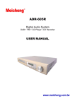
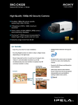
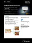
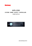
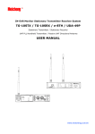
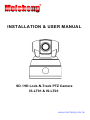
Meicheng R INSTALLATION & USER MANUAL SD / HD Lock-N-Track PTZ Camera IS-LT01 & IS-LT03 www.meicheng.com.tw Safety Notes Read all safety rules and instructions carefully before starting to install and run the device. 1. Refer to trained and qualified personnel to do the installation and maintenance, pay attention to local electricity rules. Keep the safety notes and instructions for future reference. 2. When you open the box and take out the camera parts, avoid shock to them, any man-made damage to the device does not fit the warranty. 3. Make sure the installation related materials or places can stand up to 4 times the weight of the device. 4. Always use the power adaptor (DC12V) provided with device, do not overload the electrical power and the extensions that may cause unexpected damage to the device. Table of Contents About the product ........................................................................................... 1 Features ......................................................................................................... 1 Characteristics & Functions ........................................................................... 1 Operation Instructions .................................................................................... 1 Product Structure ........................................................................................... 2 Technical Parameters .................................................................................... 3 Installation instructions.................................................................................. 4 Parts List ........................................................................................................ 4 Size and Dimension Chart ............................................................................. 4 Camera Pole Mount Installation Steps ........................................................... 6 Installation Notes ............................................................................................ 7 Menu operations ............................................................................................. 8 Start Up Information ....................................................................................... 8 Camera Control .............................................................................................. 8 Tracking Setting ........................................................................................... 10 Set valid tracking area .................................................................................. 14 Set Projection Screen Area .......................................................................... 18 Start/Stop Tracking....................................................................................... 19 Troubleshooting ............................................................................................ 20 About the product Features The SD / HD Lock-N-Track PTZ camera(hereinafter referred to as camera) adopts the most advanced intelligent video analysis technology to detect, lock and track moving object; it can realize smooth tracking performance automatically without extra sensor(s). It can precisely lock the moving object in the center of the image, convenient to use. With its stability, easy-to-use and excellent performance, it is widely used in electronic classroom, technical training and video conferencing room, etc. Characteristics & Functions Supports up to 1080p resolution, 20x optical zoom. With advanced image algorithm to detect and track moving object, excellent tracking performance with high stability. Automatically Lock-N-Track moving object, when tracking, any change of light, object’s gesture, interference of other moving object , light source or video from projector will not affect the tracking effect. Smooth tracking performance, no shaking image. With smooth and soft auto zooming function, always keep the object in the center of image with appropriate size. Easy to set effective tracking area and other value. Easy and simple installation, debugging and operation. Operation Instructions Address, baud rate and protocol Every camera has its fixed address (1), baud rate(9600bps) and protocol (Pelco D), set these settings accordingly from your controller to control. 1 About the product Save and call preset Preset function is that camera saves current horizontal angle, tilt angle of pan/tilt, zoom and position parameters into memory. When necessary camera calls these parameters and adjusts Pan/Tilt/Zoom to that position accordingly. User can save and call preset easily and promptly by using keyboard controller, DVR or other controllers. Product Structure The device consists of aux camera and tracking camera, see below picture. Aux Camera PTZ Tracking Camera Loc-N-Track PTZ Camera Tracking camera: does pan/tilt/zoom, locks moving object to track, thus to get clear image of the tracked object. Aux camera: detects moving object and then does video analysis, by communicating with tracking camera, drives the tracking camera to track moving object. All settings are set in Aux camera’s OSD menu. 2 About the product Technical Parameters Specifications Item IS - LT01 Video System IS-LT03 HD:1080p/30,1080p/29.97, 1080p/25,1080i/60,1080i/59. 94,1080i/50,720p/60,720p/5 9.94,720p/50,720p/30, 720p/29.97,720p/25 PAL/NTSC SD: NTSC(CROP), NTSC(SQUEEZE), PAL(CROP),PAL(SQUEEZE) Image Sensor 1/4 inch SONY EXview HAD Effective Pixel Resolution Optical Zoom 752(H)×582(V) 550TVL 18x Digitall Zoom 12x 1.0±0.2Vp p:75Ω composite Video Output 1/2.8inch Exmor CMOS Sensor 3.27megapixel 20x 12x - S/N Min. Illumination Synchronization BLC Lens ≥50dB F1.4,f=4.1~73.8mm Field of View Wide 48°/ Tele 2.8° 0.02Lux P/T Speed 0.095 Lux(F1.6, ICR on) Internal Open / Close / Auto (F1.6-F3.5),f=4.7mm-94mm 1080 p mode: Wide 55.4°/ Tele 2.9° 720p mode: Wide 37.6° / Tele 2.0° Pan(0.1°~150°/sec); Tilt(0.1°~120°/sec) P/T Angle Pan: 340°; Tilt: -30~90° Preset Number Video Output Interface Control Interface Baud Rate Protocol 64 VBS HD: Analog Component(Y/Pb/Pr), SD: VBS RS-485 9600BPS PELCO-D Working Temp 0℃~+50℃ Storage Temp -20℃~+70℃ Humidity 0~95(non-condensing) Power Supply DC 12V Power <20W Dimension 160(D)×206(H)mm 3 Installation Instructions Parts List The camera supports Pole or Stand installations, when you open the box, please check below lists carefully; if you found missing parts, please contact your supplier, otherwise the installation cannot be completed. Item in package Quantity Unit PTZ Camera Aviation Plug Optional pole installation parts Pole Bracket Pole Base Optional tripod installation parts Tripod with Cylinder 1 1 PC PC 1 1 PC PC 1 PC Size and Dimension Chart Size and hole dimension chart Fixing Plate Pole Mounting Plate Size Dimension of Camera 4 Pole Bracket Size Installation Instructions Hole Locations of Fixing Plate Size Dimension of Mounting Plate Aviation Plug Entry Cable Connecting Interface at Camera Base Power Cable RS485 Cable Aux Camera Video Cable Tracking Camera Video Cable Tracking Camera Component Video Cable (HD) Aviation Plug 5 Installation Instructions Camera Pole Mount Installation Steps Before installing, locate correctly the position of the pole according to its horizontal angle; make sure the aux camera is pointed directly to the blackboard. Pole bracket installation Pull the aviation plug through the pole bracket; reserve enough length of cable outside the pole bracket that is used for further installation; then, according to hole dimension of the fixing plate, fix the pole bracket, by using setscrews, onto the ceiling. Pole base installation Pull the aviation plug through the pole base, then fix the pole base and pole bracket by the screw thread. [Note] must fix tightly to ensure safety. Cable connection After fixing the pole bracket, connect the aviation plug to the related interface at the camera base. Make sure to connect correctly, and then tighten it. Camera Installation Fix the three bolts at the camera base to the pole base’s three holes, and then tighten it. [Note] Make sure the aux camera is pointing directly to the blackboard; otherwise, adjustment to the pole position is required to reposition. Then screw up the two bolts from the pole base to the camera base, fix the camera’s horizontal position. Finally the installation is finished as below picture. 6 Installation Instructions Finished Installation Picture Installation Notes Camera must be installed in the right ahead of blackboard with distance 7~10 meters, suggested distance from the camera to floor is 2.7 meters. [Note1] Keep the camera base at the horizontal position. [Note2] Make sure the aux camera is pointed directly to the blackboard. 7 Menu Operations Start Up Information After the camera is powered up, the tracking camera will do self-testing by its pan and tilt direction, then reaches its preset number 1. Before the tracking camera reaches preset number 1, the aux camera will pop-up below window. After tracking camera reaches preset number 1, it will start auto tracking. If moving object appears in the scene, there will be red rectangular frame around the moving object. Address: 1, Pelco-D, 9600 Call 80# to begin tracking Call 95# to set parameters Ver 1.4 Camera Control Our keyboard controller, remote controller, other PC based control software or any other controllers can be used to control the camera. However, address, baud rate and protocol from controller should be set exactly the same as the camera’s actual settings. Below Chart shows the available presets and their relative functions for camera control and value settings. Presets & Functions Preset 1 2 3 4-64 80 81 83 8 Function starting tracking position Closest tracking position Close-up tracking position, work with ultrasonic locator Regular preset positions Call this preset to start auto tracking Call this preset to stop tracking Auto iris mode Menu Operation 84 86 87 90 91 92 93 95 96 Manual iris mode Auto WB mode Set manual WB to push and trigger mode Manual focus mode Auto focus mode Image flip on of tracking camera Image flip off of tracking camera Call this preset to enter / exit menu Set this preset to save values For HD version (the tracking camera is HD camera), below chart shows also the presets & related functions to switch from different video outputs. [Note] when switching video outputs, the camera must be stopped from tracking and its OSD menu was exited. After switching, rebooting is required to take the new video output into effect. HD Video Output Switch Preset Model 111 112 113 114 115 116 117 118 119 120 121 122 123 124 125 126 IS-LT01 Video Output Switch IS-LT02 1080i/59.94 720p/59.94 NTSC(CROP) NTSC(SQ) 1080i/50 720p/50 PAL(CROP) PAL(SQ) - IS-LT03 1080i/59.94 720P/59.94 NTSC(CROP) NTSC(SQ) 1080i/50 720p/50 PAL(CROP) PAL(SQ) 1080i/59.94 1080p/30 1080p/29.97 1080p/25 720p/59.94 720p/30 720p/29.97 720p/25 9 Menu Operation After powering up, the camera automatically gets into tracking mode. If tracking settings needs to be made, the camera must be stopped from tracking. The way to judge whether the camera is on tracking or non-tracking status is: if there is red character shown, it is on non-tracking status. In non-tracking mode, CALL preset 95 to enter / exit main menu. Press Iris OPEN button of your controller to confirm, then gets into submenu. CALL preset 95 to get into main menu => 1. Set tracking parameters => 2. Set valid area => 3. Set projection screen area 1. Set tracking parameters:has 4 submenus, set according to actual requirement. 2. Set valid area:has 6 submenus, set according to actual working environment. 3. Set projection screen area:has 4 sub-menus, set once projector is used in actual working environment. After settings are made from every further sub-menu, Set preset 96 to save current settings. If no setting is made from every further sub-menu, Set preset 96 will exit the menu without saving settings. If setting needs to be made again, Call preset 95 to get into menu again and Set preset 96 to save settings again Tracking Setting Sub-menu 1.Set tracking parameters has below settings: Set Tracking Speed, Set Tracking Sensitivity, Auto Zoom (on/off) and Auto Tilt Motion (on/off). 10 Menu Operation Set Tracking Speed Scroll to 1. Set tracking parameters, press OPEN to confirm and get into Set Tracking Speed. Set Tracking Speed => - There are 7 levels, camera defaults middle level; scroll up / down to choose from different levels. Scroll up to increase speed, scroll down to decrease speed, press OPEN to confirm, and then get into Set Tracking Sensitivity. Set Tracking Sensitivity Set Tracking Sensitivity ! ! ! ! ! ! ! * If tracked object’s moving range is large but you want the camera to keep still, then decrease the tracking sensitivity by moving the cursor rightwards. If the tracked object’s moving range is large and you want the camera to move accordingly, increase the tracking sensitivity by moving the cursor leftwards. Choose from 7 tracking sensitivity levels, press OPEN to confirm and get into Auto Zoom Setting. 11 Menu Operation Auto Zoom (on/off) 1. Auto zoom ON 2. Auto zoom OFF Auto Zoom On: camera will auto zoom when tracking. Auto Zoom Off: camera will not auto zoom when tracking. [Note] If the tracked area is small, Auto Zoom Off is suggested. Choose from ON /OFF options, press OPEN to confirm and get into Auto Tilt Motion Setting. Auto Tilt Motion (on/off) 1. Auto tilt motion ON 2. Auto tilt motion OFF Auto Tilt Motion On: camera will tilt when tracking. Auto Tilt Motion Off: camera will not tilt when tracking. Choose from ON /OFF options, press OPEN to confirm. This is the last step of Set Tracking Parameters 12 Menu Operation At this step, Set preset 96 to confirm settings. [Note] Should be Set instead of Call preset 96. Then below window will pop up indicating the settings are saved, Call preset 95 to exit the menu Save track parameters complete! Call 95# again to exit setting After preset 95 is called, it will exit OSD and below window pops up. Exit, Track parameters saved. Address:1, Pelco-D, 9600 Call 80# to begin tracking Call 95# to set parameters If, in the last step, Set preset 96 has not been conducted but preset 95 is called to exit menu, then below window will pop up indicating that the setting has not been saved. Call preset 95 to get into menu again and set until the final step and Set preset 96 to save settings again. [Note] Even if the settings are not saved, the settings are valid before rebooting. 13 Menu Operation Exit, Track parameters NOT saved !! Address:1, Pelco-D, 9600 Call 80# to begin tracking Call 95# to set parameters Set valid tracking area Scroll to 2. Set valid area, press OPEN to confirm and get into Set Top Boundary . Set Top Boundary A green rectangular frame and instructions will pop up. Set top boundary, then press ‘Iris Open’ button to confirm and go to next step. Move the rectangular up/down to set the top boundary; suggested to set abreasting to the upper side of blackboard. Press OPEN to confirm and get into Set Bottom Boundary . Set Bottom Boundary A yellow rectangular frame and instructions will pop up. 14 Menu Operation Set bottom boundary, then press ‘Iris Open’ button to confirm and go to next step. Move the rectangular up/down to set the bottom boundary, suggested to set abreasting to the first row of students. Press OPEN to confirm and get into Set Right Boundary. Set Right Boundary A blue rectangular frame and instructions will pop up.. Set right boundary,then press ‘Iris Open’ button to confirm and go to next step. Move the rectangular up/down to set the right boundary, suggested to set to a rightmost position where the lecturer can reach. Press OPEN to confirm and get into Set Left Boundary Set Left Boundary A cherry rectangular frame and instructions will pop up.. 15 Menu Operation Set left boundary, then press ‘Iris Open’ button to confirm and go to next step. Move the rectangular up/down to set the left boundary, suggested to set to a leftmost position where the lecturer can reach. Press OPEN to confirm and get into Set Head Top Line . Set Head Top Line A blue horizontal line and instructions will pop up.. Set head top line, then press 'Iris Open' button to confirm and go to next step. From the blackboard, draw a horizontal line that is 1.7 meter high from the floor, move the blue horizontal line to fit the horizontal line on the blackboard. Press OPEN to confirm and get into Set Preset 1, 2 and 3 setting. Set Preset 1, 2 and 3 A red rectangular frame and instructions will pop up.. 16 Menu Operation Control teacher-camera to set 1#, 2#, 3# preset positions according to 'User Manual', then set 96# to save parameters. At this step, moving up/down/left/right and zoom of the camera is possible; if in other menu / sub-menu, movement from controller can only move the cursor or image in the menu. This is the last step of 2. Set valid area, to set preset 1,2 and 3, see below sketch for details. Preset 1 Preset 1 is the starting position for tracking, for example, the lecturer is 1.7 meter tall standing in front of the blackboard, his/her head is of the same height as the green line; move the camera’s pan/tilt/zoom to put the lecturer in the appropriate position and size in the image, then set it as preset 1; this position is the actual tracking position where lecturer stands the closest to the blackboard. Preset 2 Preset 2 is the closest tracking position, have the lecturer walk down platform, put his/her head inside the red rectangular frame; move the camera’s pan/tilt/zoom to put the lecturer in the appropriate position and size in the image; this position is the actual closest tracking position where the camera is the closest to the lecturer. 17 Menu Operation Preset 3 Preset 3 is the close-up preset, in case the lecturer stands still in front of the platform for a long time when lecturing and the camera keeps tracking. With ultrasonic locator installed in front of the platform and Set preset 3 accordingly, once the locator detects the lecturer, the camera will automatically locate at preset 3 without tracking other object(s). Thus, usually when setting preset 3, based on platform, move the tracking camera to a position that covers the lecturer’s appropriate position and size. Preset 3 can also be set at any other position if required. [Note] For proper tracking performance, Preset 1 should be set at the position where camera reaches its appropriate big zoom tele (6x for example) and highest vertical height; and the preset 2 should be set at the position where camera reaches its appropriate small zoom wide (with biggest view angle, 2x for example) and lowest vertical height. That is, the preset 2 has more expanded view angle and lower vertical height. Otherwise, the values cannot be saved. Finally, Set preset 96 to save the boundaries and presets; when saving, window shows “Saving parameters……”, wait until below window pops up and Call preset 95 to exit menu Save parameters complete! Call 95# again to exit setting Set Projection Screen Area This part includes 4 steps, which are the same as the settings of “Setting valid tracking area”. After setting, Set preset 96 to save settings. 18 Menu Operation [Note] the area can be set according to the actual projection area in the projection screen, no need to cover the whole screen. Anti-projector interference function (Open / Close) To open anti-projector interference, set the bottom boundary of the projection area higher than the bottom boundary of valid tracking area, Set preset 96 to save setting. To close it, set the bottom boundary of the projection area lower than the bottom boundary of valid tracking area, then the camera will figure out that there is no projection area and the anti-projector interference function will be closed. The anti-projection interference function is closed in default setting. Start/Stop Tracking After powered up, the camera automatically starts tracking. Call preset 81 to stop tracking. Call preset 80 to start tracking. Menu is only accessible in non-tracking mode; and tracking can only be activated after existing menu. 19 Troubleshooting Problem Power up but no action or image Self-testing but no image Self-testing does not proceed, or with noise Tracking target not in the center of image “Tilt logic error” when saving valid area parameters “Zoom logic error” when saving valid area parameters 20 Possible Cause Power supply failure Switch power supply failure Power cable is disconnected Video cable is not correctly connected Camera is defective Not enough power Mechanical failure Pan / Tilt compensation problem Tilt height of 1# preset from tracking camera is lower than tilt height of 2# preset Zooming times of 1# preset from tracking camera is less than zooming times of 2# preset Solution Check power supply Change switch power supply Reconnect power cable Reconnect video cable Change camera Check power cable Need repairing Get into main menu to adjust pan/tilt compensation parameters Get into main menu and adjust tilt height of 1# to be more than 2# preset Get into main menu and set the zooming times of 1# preset to be more than 2# preset. Meicheng Audio Video Co., Ltd. Address: 13F., No.2, Jian 8th Rd., Zhonghe Dist., New Taipei City 235, Taiwan TEL: 886-2-82280311 FAX: 886-2-82280319 E-mail: [email protected]