1
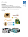
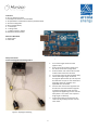
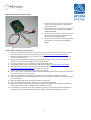
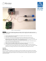
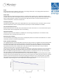
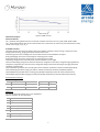
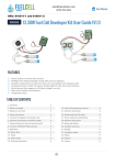
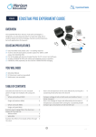
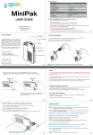
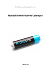
 12‐30W Fuel Cell Developer Kit User Guide (V1.1) Table of Contents Page 1. Overview 2 2. What is included 2 3. What you will need 2 4. Setup Instructions 2 5. Connect H2 regulator and purge valve 2 6. Electrical connections to Arduino shield 2 7. Prepare Arduino and fuel cell control shield 2 8. Connect HydroSTIK and load 2 9. Operation 2 10. Status LEDs 2 11. Purge 2 12. Waste water 2 13. Overload protection 2 14. Fuel cell maintenance and use 2 15. Software downloads 2 16. Monitoring fuel cell status 2 17. Power output & conditioning 2 18. Software description 2 19. Setup and defines 2 20. Available functions 2 21. Storage 2 22. Hydrogen supply 2 23. Safety 2 24. Support 2 25. License 2 Features • Control system for Horizon fuel cell stack • Refillable metal hydride hydrogen storage with pressure regulators • Complete component kit to build and create your own hydrogen fuel cell power plant • Development board "shield" for popular Arduino platform with stack control software • Monitoring and data‐logging via USB (stack voltage & current) • Open source hardware and software • Unregulated output 1 Document Overview The Developer Kit enables the user to easily design and build fuel cell systems using a Horizon H‐12 or H‐30 PEM fuel cell stacks to deliver up to 12W or 30W respectively. An open source platform supported by an online developer forum encourages rapid customisation of systems, control and user interface for a wide range of applications from model trains, planes and automobiles, to remote monitoring systems. This manual doesn't attempt to replace the manual that comes with the fuel cell stack. Read the fuel cell manual to get an understanding of how to properly treat the stack. This manual covers shields v1.3 or above. If you have a shield with a lower version number please contact us directly at [email protected] Photographs in this guide show the H‐12 stack, but instructions apply equally the H‐30 stack. What Is Included 7 8 5 6 4 2 3 1 Figure 1. What is included Figure 2. 12W stack Figure 3. 30W stack 2 In the box H‐12 or H‐30 fuel cell stack 1. Developer Kit Arduino Fuel Cell Shield 2. 2x HydroSTIK. Pre‐filled where delivery method allows 3. 2x Pressure Regulator 4. Silicon tubing (30cm) 5. 1 x Tube Clip 6. 1 x Purge valve 7. 1 x Silicon tubing T‐splitter 8. Red/black electrical cable What You Will Need 1. Arduino Uno 2. USB Cable Setup Instructions Figure 4. Arduino Connect H2 Regulator And Purge Valve 1. Cut a short length of silicone tube (approx 3cm) 2. Push one end of the short length onto the white nozzle of the purge valve 3. Push the other end of this tube onto the outlet nozzle of the fuel cell stack 4. Cut a longer piece of silicone (about 8cm) 5. Thread the longer length of silicone through the plastic tube clip. This clip will be used later to open or close the flow of hydrogen whilst the regulator and HydroSTIK are connected 6. Unscrew the nut from the regulator and thread one end of the tube through the nut before pushing the tube onto the regulator and tightening the nut over the tube (there is no need to use a spanner ‐ finger‐tight is sufficient) 7. Connect the other end to the fuel cell stack inlet by pushing the tube over the inlet nozzle Figure 5. Hydrogen Plumbing 3 Electrical Connections To Arduino Shield 1.
2.
3.
4.
Take the red wire from the fuel cell stack and connect to the end terminal on the Arduino shield labeled FC IN Take the black wire from the fuel cell stack and connect to the next terminal on the Arduino shield labeled GND Connect one wire (doesn't matter which of the two) from the purge valve to the terminal on the Arduino shield labeled PURGE Connect the other wire from the purge valve to the terminal on the Arduino shield labeled PURGE Figure 6. Electrical connections Prepare Arduino and fuel cell control shield 1. If you do not already have the Arduino environment and drivers installed on your computer, follow these instructions, relating to your operating system (http://arduino.cc/en/Guide/HomePage) 2. Before proceeding, make sure you can open an example Arduino sketch (e.g. blink), compile it and upload. If so; then proceed. 3. Plug the Fuel Cell Shield into the Arduino Uno taking care that all the pins on the underside of the shield slot into the holes in the Arduino Uno stackable header 4. Connect your Arduino to your computer using a standard USB cable 5. Download the latest version of the Developer Kit Arduino Library (arcolaenergy.com/developer) 6. Unzip the library in the libraries directory in your sketchbook folder (see http://arduino.cc/en/Guide/Libraries for further instructions) 7. Launch the Arduino Environment software on your computer 8. In the "Tools" menu, check that you have correct Board selected (Arduino Uno) and correct Serial Port (see Arduino Help if you are uncertain) 9. Open the example file in the Arduino Environment: "File", "Examples", "H2MDK", "h2mdk" 10. Check the definitions for the stack and shield are set correctly. See the section on software defines for more information 11. Click the "Upload" button to upload the software to the Arduino 12. Open the Serial Monitor from the Tools menu in the Arduino Environment 13. Check that the baud rate (bottom‐right of the window) is set at 9600. You should see text appear in the Serial Monitor window to indicate that the software is running. 14. You should also see activity on the LEDs, whilst the capacitors are charging the status LED will flash ever half second, once the capacitors are fully charged the status LED will flash every second 4 Connect HydroSTIK And Load Figure 7. Connect HydroSTIK Important The fuel cell stack requires unobstructed airflow to all vents in order to function as the oxygen used in the electrochemical reaction is drawn through these vents. Obstructed air supply will reduce the performance and lifetime of your stacks. 1. Ensure the plastic clip on the tube between the regulator and the inlet valve is closed 2. Screw a HydroSTIK into the regulator 3. Ensure stack is mounted or positioned so that the vents on both sides are open to the air 4. Open the clip on the tube to allow hydrogen to flow into the fuel cell stack. It is normal for the HydroSTIK to get cold during operation ‐ how cold will depend on factors including current drawn and ambient temperature. The fans on the fuel cell should start spinning 5. You can now connect the negative wire of your electrical load to the terminal marked GND and the positive wire to the terminal marked FC OUT 6. When you wish to turn off the system, first disconnect your load from the FC OUT terminal 7. Close the clip on the hydrogen supply tube to stop the flow of Hydrogen 8. Care should be taken not to overload the stack. Ensure that the maximum current drawn by your equipment cannot exceed that which the stack can supply (12 or 30W). For more information on stack performance, including IV characteristics consult the Horizon Fuel Cell H‐Series User Guide Operation Status LEDs There are 3 LEDs: After reset, the status LED flashes twice in 200ms, and then every 400ms until the capacitors have charged. When the system is operating normally the LED will flash every second the short LED shows when the fuel cell is shorted. This maintains proper temperature and humidity inside the stack the purge LED shows when the purge valve operates. 5 Purge Every 10‐30 seconds you will hear a short "hiss" as the purge valves open. This purging allows impurities to escape from the stack, improving performance. Waste water The by‐product of the electrochemical reaction is a small amount of water. This is released through the vents on both sides of the stack. The larger the electrical load, the more water will be produced. This small amount of water usually evaporates, however occasionally under high load, droplets are formed therefore the stack should not be placed in a moisture sensitive area. Overload protection The Stack Control Shield is fitted with a replaceable fuse. If you overload (or short circuit) the output, the fuse will blow. Replacement fuses are made by little fuse (farnell part number 0454 005 for the 30W). Fuel cell maintenance and use Please check the Horizon Fuel Cell H‐Series User Guide for further instructions on use and maintenance of your Fuel Cell stack to prevent degradation due to mishandling. Software downloads Latest fuel cell stack control software is available from arcolaenergy.com/developer. The software is fully documented online, including instructions for use. Monitoring fuel cell status The fuel cell status (stack voltage and current) is displayed by default in the Arduino Serial Monitor. For further information, please see software documentation. Power output & conditioning The 12/30W Developer Kit Fuel Cell Shield controls the fuel cell, but does not regulate the output power (unlike the 3W Shield which has inbuilt voltage regulation and smoothing). Thus the voltage you see across the load terminals of the Shield is that of the fuel cell stack. Furthermore, by default the Shield short‐circuits the stack periodically to maintain stack condition and in this time the power output will drop to zero (an onboard capacitor maintains power to the Arduino during shorting). One of the first projects you will likely undertake is to add power conditioning. Depending on the requirements of your load (e.g. 12V, 24V), you should be able to find an off‐the‐shelf DC‐DC convertor to suit your needs. Refer to the Battery Charger document for a suitable converter. For advanced users, you can of course build your own, making use of the Pulse Width Modulation output from the Arduino. The plots below show the characteristics of the H‐12, H‐20 and H‐30 as supplied off‐the‐shelf by Horizon. Note that the H‐20 is the same physical stack as the H‐12, but it can deliver more power because the H‐12 is supplied without any fuel cell control (short‐circuiting and purging). Knowing this you can decide whether to simplify your system and run without short‐circuiting at lower power or increase complexity by adding capacitors to smooth the output during short‐circuit and therefore achieve higher power. Figure 8. 12W IV curve 6 Figure 9. 30W IV curve Software description Setup and defines The _stacksize setting defines the size of the fuel cell stack and can be one of V1_5W, V3W, V12W V30W The _shield setting defines the version of the shield. This is printed on the reverse of your shield and currently can be one of V1_0, V1_2, V1_3 Available Functions void poll() This function must be called at least every 100ms to keep the stack running. It takes care of the timings of the shorting, purging and measurement of the stack. void status() prints a short voltage and current measurement to the hardware serial port float getVoltage() returns the stack voltage as a floating point number float getCurrent() returns the stack current as a floating point number void start() configures the code and blocks until the capacitors are charged void overrideTimings( unsigned int shortCircuitInterval, unsigned int shortTime, unsigned long purgeInterval, unsigned in purgeTime) This can be used to change the timings of the stack shorting and purging. All values should be in milliseconds void enableShort () Enables short circuiting of stack to maintain membrane condition (enabled by default) void enablePurge () Enables purging of stack to maintain membrane condition (enabled by default) void disableShort () Disables short circuiting (only disable temporarily as this will reduce performance) void disablePurge () Disables purging of stack (only disable temporarily as this will reduce performance) Default Software Timings Table 1. Timings fuelcell short circuit interval short circuit time purge interval purge time 12W 10s 100ms 25s 100ms 30W 10s 100ms 10s 100ms Shield Pins You should avoid using these pins in your application Table 2. Hardware v1.3 pin allocation Pin Function 3 Purge 5 Short circuit 6 Status LED A1 Stack voltage sense A2 Stack current sense A3 Capacitor voltage sense AREF Connected to Arduino's 3.3v pin 7 Storage Important The fuel cell stacks will degrade if they are allowed to dry out. Therefore whenever the fuel cell stack is not be used for more than one hour, it should be stored in the sealed airtight bag. Hydrogen supply Where delivery method permits, your Developer Kit will be supplied with pre‐filled HydroSTIK. To refill your HydroSTIK we recommend that you purchase a Horizon Fuel Cell HydroFILL home electrolyser which generates hydrogen from electricity and distilled water. HydroFILL can run on mains electricity or on DC. For more information see the Horizon fuel cell website. Safety WARNING: Fire Hazard This is not a toy, keep away from children Read and Understand Operating instructions before use HydroSTIK contain flammable gas under pressure (most of the hydrogen is adsorbed by the metal hydride matrix but the voids are filled with gas at circa 20bar) Do not tamper with HydroSTIK. Under no circumstance should a cartridge be disassembled. Exposure to air will render the hydride material useless. Materials within the hydride are potentially dangerous. When using this kit, basic safety precautions should always be followed to reduce risk of fire, electric shock or personal injury Do not disassemble the fuel cell stack, damage will result and your warranty will be void. Stack membrane materials may be hazardous to health Keep away from alkaline and acidic environments This kit is supplied as a test and development tool. Do not use it to power safety critical appliances License This documentation, the hardware and the software are all released under the GPL v3 license 8