1
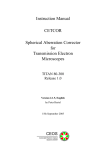
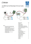
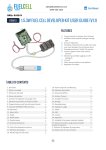
MT Explorer 50 Ion Trap Mass Spectrometer User Manual Version 1.2 MassTech Inc. 6992 Columbia Gateway Drive, Suite 160 Columbia, MD 21046 USA Phone +1 (443) 539-1758 Fax +1 (443) 539-1759 Email [email protected] Web www.apmaldi.com MT Explorer 50 Warning The MT Explorer 50 Ion Trap Mass Spectrometer is produced with a variety of components which should only be serviced by qualified personnel. For maintenance or repair issues, please contact your sales agent or the manufacturer directly: MassTech Inc. 6992 Columbia Gateway Drive, Suite 160 Columbia, MD 21046 USA Phone +1 (443) 539-1758 Fax +1 (443) 539-1759 Email [email protected] ii MT Explorer 50 COPYRIGHT NOTICE All rights reserved including the right of reproduction in whole or in part of any form. This document may be electronically reproduced, distributed, or printed in its entirety provided this copyright and statement are attached. Any modification or any other reproduction, distribution, or use of this document or portions hereof is strictly prohibited without the express written permission of MassTech, Inc. COPYRIGHT 2012. All rights reserved. TECHNICAL NOTICE Technical information contained in this publication is for reference purposes only. Contents of this manual are subject to change without notice. While every effort has been made to supply accurate and complete information, MassTech Inc. assumes no responsibility and will not be liable for any errors, omissions, damages, or losses that might result from any use of this manual or the information contained therein (even if this information is properly followed and problems still arise). Revision History: Version 1.0 Created January 2013 Version 1.1 Updated July 2013 Version 1.2 Updated October 2013 Software Edition: Modas 3.2 Operating System: Microsoft Windows XP Service Pack 3 or Windows 7 iii MT Explorer 50 This page is left intentionally blank. iv MT Explorer 50 Table of Contents PREFACE ............................................................................................................................ VII 1 PRINCIPLE OF OPERATION ......................................................................................1 2 MAJOR COMPONENTS ...............................................................................................5 3 INSTALLATION AND STARTUP PROCEDURES ...................................................7 3.1 3.2 3.3 3.4 3.5 3.6 UNPACKING .............................................................................................................................. 7 INSTALLATION REQUIREMENTS ................................................................................................. 7 SYSTEM INTERFACE: FRONT PANEL ........................................................................................... 7 SYSTEM INTERFACE: BACK PANEL ............................................................................................ 8 MT EXPLORER 50 START-UP .................................................................................................... 9 INSTALLATION OF MODAS: MT EXPLORER 50 OPERATING SOFTWARE ....................................... 9 4 INSTALLING AN ION SOURCE ................................................................................ 11 5 MODAS SOFTWARE AND OPERATIONAL INSTRUCTIONS ........................... 13 5.1 5.2 5.3 5.4 5.5 5.6 5.7 5.8 5.9 5.10 5.11 5.12 5.13 5.14 5.15 5.16 5.17 STARTING SOFTWARE ............................................................................................................. 13 STARTING MS OPERATION ...................................................................................................... 13 ION POLARITY MODES ............................................................................................................ 16 ADJUST ION SOURCE VALUES ................................................................................................. 16 ADJUST ION OPTICS VALUES ................................................................................................... 17 ADJUST DETECTOR VALUES .................................................................................................... 18 SELECTING METHOD OF MS OPERATION ................................................................................. 19 CONTINUOUSLY SCAN MS SPECTRA ........................................................................................ 19 RECORD SPECTRA ................................................................................................................... 20 REVIEW SAVED SPECTRA ........................................................................................................ 21 COLLECT MS-MS SPECTRA: ISOLATION AND FRAGMENTATION ............................................... 22 RETURNING TO THE MS MODE FROM THE MS-MS MODE. ....................................................... 24 EXPORTING DATA. .................................................................................................................. 24 OPTIONS DIALOG BOX ............................................................................................................ 25 REPORTS ................................................................................................................................. 28 EXTERNAL CONTROL. ............................................................................................................. 28 ADVANCED SETTINGS (POWER USER ONLY)............................................................................ 31 6 SHUT-DOWN PROCEDURE ..................................................................................... 32 7 MAINTENANCE AND TROUBLESHOOTING ....................................................... 34 7.1 7.2 7.3 7.4 8 SCHEDULED MAINTENANCE .................................................................................................... 34 TROUBLESHOOTING ................................................................................................................. 34 MASS RECALIBRATION (POWER USER ONLY) .......................................................................... 35 ELECTRON MULTIPLIER VOLTAGE ADJUSTMENT (POWER USER ONLY) ................................... 40 WARRANTY INFORMATION ................................................................................... 44 APPENDIX A: QUICK-GUIDES FOR NORMAL OPERATION ................................... 46 APPENDIX B: CHROME EXPLORER DATA VIEWER INSTRUCTIONS ................ 52 APPENDIX C: REPLACING THE MH CARTRIDGE .................................................... 55 v MT Explorer 50 This page is left intentionally blank. vi MT Explorer 50 PREFACE The following symbols are used in this manual to indicate material that should especially be noted because it relates to safety issues. This symbol in the manual margin is used to emphasize the presence of very important operating instructions related to safety especially during: installation, removal, maintenance and troubleshooting. Operators are strongly encouraged to read this manual before installation, removal, operation, maintenance, or troubleshooting. Operators should pay special attention to paragraphs marked by . DO NOT ATTEMPT services or repairs that are not covered in the Troubleshooting Section (Section 7) of this manual. For services and repairs beyond those specifically provided in the Troubleshooting section, contact the manufacturer: MassTech, Inc. 6992 Columbia Gateway Dr. Suite 160 Columbia, MD 21046 (443) 539-1758 vii MT Explorer 50 This Page is left intentionally blank. viii MT Explorer 50 1 PRINCIPLE OF OPERATION The MT Explorer 50 is a miniaturized Ion Trap Mass Spectrometer (ITMS). Its major features include: atmospheric pressure interface (API) to use various atmospheric pressure ionization sources, high mass range (up to 2500 Da -with some options), small size (12x17x20 inches), and low power consumption. It consists of API (atmospheric pressure ionization) ion optics to deliver ions to the mass analyzer, ion trap mass analyzer, and the ion detection system enclosed within the vacuum manifold. At the front-end, the interchangeable atmospheric pressure (AP) ionization source (IS) is attached externally to the ITMS, which is a standard feature of the modern laboratory mass spectrometers. The AP ionization sources are efficient and can encompass analysis of a wide range of chemicals using the same mass analyzer; ionization of the sample takes place in the APIS. The specific front-end method used to ionize the sample is referred to as the ionization technique and can include the following: chemical ionization (APCI), electrospray ionization (ESI), secondary electrospray ionization (sESI), matrix assisted laser desorption ionization (MALDI), direct analysis in real-time (DART), desorption electrospray ionization (DESI), and other methods of atmospheric pressure ionization. As the mass analyzers operate in the vacuum, an atmospheric pressure interface serves as the function of an ion delivery from the atmospheric (ambient) pressure conditions (existing in the ion source of a mass spectrometer) to the vacuum of the mass analyzer. This ion delivery process has to occur with minimal ion loss for further mass spectrometry analysis. A block diagram with the main components of the ion optics, vacuum system, and electronics of the MT Explorer 50 is presented in Figure 1.1. Figure 1.1. Block diagram for MT Explorer 50 and its major components. Ions produced in the source are introduced to the mass spectrometer (MS) through a heated stainless steel inlet capillary which has 180 μm i.d. The air intake is 80-100 cc/min, depending on the inlet capillary temperature. 1 MT Explorer 50 The instrument has two vacuum sections. Each section is evacuated by a turbo pump. The turbo pump in the first vacuum section and is backed by a diaphragm pump. The exhaust of the turbo pump in the second vacuum section, which is connected to the first vacuum section of the instrument, provides low backing pressure for its operation. The majority of the gas flow from the heated inlet capillary is pumped out through the first vacuum section, making the gas flow that reaches the second vacuum section of the instrument negligible. With the inlet capillary temperature at 200 °C, the pressure in the first vacuum section of the instrument is about 15 mTorr while the background air pressure in the second vacuum section is at 10-5 Torr range. The ion guide optics focuses and accelerates the sample ions transmitted through the inlet capillary into the mass analyzer, where they are trapped in stable orbits by a time-varying electric field. The polarity of the potentials applied to the ion source and ion optics elements, determines whether the positively or negatively charged ions are transmitted to the mass analyzer; this ion polarity mode is selected by the user. The ion guide optics are hexapoles composed of six parallel rods equidistantly positioned around the hexapole central axis. A superimposed radiofrequency (RF) potential is applied to the hexapole rods to create a trapping electric field confining ions near the hexapole center axis. The ion transfer system of the instrument includes the inlet capillary and two hexapole ion guides, one per each stage of the vacuum system which is separated by the conductance-limiting diaphragms. The conductancelimiting diaphragms restrict the gas flow entering either section while minimizing the ion losses due to collisions. Ions are propelled from the inlet capillary to the mass analyzer by applying small accelerating voltages to the ion guide elements (typically 5-10 V). Additionally, these voltages are used to gate ions coming from IS so that they reach the mass analyzer during the injection period, but only when the trap is filled by the ions. This function is controlled by an automatic gain control (AGC) of electronics that sets the optimum number of ions to the mass analyzer by altering the injection time. The mass-to-charge ratios of the produced ions are measured by the ion trap mass analyzer. Selected ions are stored in an evacuated cavity (i.e. ion trap) by applying the appropriate electric fields; a very small amount of a light buffer gas (H2 or He) is supplied to the ion trap. The main functions of the buffer gas, required for ion trap operation, includes ion cooling towards the center of the trap and ion fragmentation in collisions with the buffer gas molecules. Ions can be ejected from the mass analyzer selectively according to their masse-to-charge ratio. Schematically, the layout of an ion trap resembles two electrodes called “end caps” (which are either grounded or biased with DC or AC potentials) and the third ring electrode is between the end-caps (a sinusoidal RF high voltage is applied to it). 2 MT Explorer 50 A batch of ions in the ion trap cell is constrained by this oscillating electric field. Some of the ions will have stable trajectories and remain trapped, whereas, others will have unstable trajectories and will be ejected through a hole in the exit end cap electrode. These ions will pass through an exit lens and reach the ion detection system where they produce a signal proportional to the number of ions detected. The ion detection system consists of a “conversion dynode” electrode (with high voltage up to ±10 kV applied to it) and a discrete-dynode electron multiplier. The ion current from the detection system is amplified by a preamplifier and is then communicated to the data system for further processing, storage, and display. Each sequence of loading the mass analyzer with ions followed by mass analysis of the ions, is called, a scan. The MT Explorer 50 uses several different scan modes/types to load, fragment, and eject ions from the mass analyzer; this allows the user to do MS and tandem MS (MS/MS) experiments. This MT Explorer 50’s ability to vary the scan mode/type, ion polarity, and having an interchangeable AP ionization source interface gives the user great flexibility in the instrumentation for solving complex analytical problems. 3 MT Explorer 50 This page is left intentionally blank. 4 MT Explorer 50 2 MAJOR COMPONENTS With external cover removed, a top view of the MT Explorer 50 is shown in Figure 2.1. Figure 2.1. Major components diagram. A. Cone with inlet capillary B. MS analyzer C. Radio Frequency (RF) coils D. Metal Hydride (MH) cartridge E. Power and electronics assemblies F. Diaphragm pump G. Instrument control modules A cross-sectional view of the internal components under vacuum of the MS analyzer is shown in Figure 2.2. Figure 2.2. A. B. orifice C. D. E. F. Cone, heating elements, and inlet capillary Ion optics: inlet hexapole ion guide and conductance limit Ion optics: MS analyzer hexapole ion guide Ion trap mass analyzer Conversion dynode and electron multiplier Pre-amplifier 5 MT Explorer 50 This page is left intentionally blank. 6 MT Explorer 50 3 INSTALLATION AND STARTUP PROCEDURES 3.1 Unpacking Lift the MT Explorer 50 out of the box and carefully set it onto a sturdy and flat surface. Use the handles located on both sides of the MT Explorer 50 to lift and set the instrument into the desired position as seen in Figure 3.1. Figure 3.1. Location of handles on MT Explorer 50. Remove the wire from the MS inlet capillary (if supplied). Note: The MT Explorer 50 weighs approximately 75 pounds (~34 kg). Two people may be necessary to lift it, i.e. one person per handle. 3.2 Installation Requirements • Dry environment on a desk or other solid surface for system set-up. • Power outlets: 115, 220 VAC and/or 28 VDC (see your system specifications) at the distance that can be reached by the MS system and laptop/PC power cables (1.8 m power cables are provided). • Ethernet cable to connect the MS system with a laptop/PC (RJ-45, 30 m maximum length – 1.8 m cable is supplied with the system). • Exhaust line (¼” I.D. plastic hose or tubing connected to a chemical hood or an appropriate fume/ventilation system – a barb connector is provided with the system). 3.3 System Interface: Front Panel Figure 3.2 is a picture of the interface front panel of the ITMS: The alignment rails and alignment stubs are used to correctly mount and position an ion source to the ITMS. The 15-pin connector and HV1 port connect directly to an ion source.The 44-pin D-sub and HV2 connect and serve as an external control for some ionization sources (additional temperature controls and HV output – see your specifications). 7 MT Explorer 50 Five light-emitting diodes (LEDs) located on the upper-right side of the ITMS front panel serve as indicators. Front Panel Indicators: Power: illuminates when the electronic assemblies and vacuum systems are supplied with power. Vacuum: illuminates when the vacuum pressures inside ITMS are within operational ranges. Ready: illuminates when the HV interlock is engaged and the system is ready to operate. Standby: illuminates when the user places ITMS in “Stand-by” mode (most control voltages are down). Operation: illuminates when the ITMS is collecting the mass spectra, i.e. in full operation of ITMS. Figure 3.2: Front panel. 3.4 System Interface: Back Panel Figure 3.3 is a picture of the interfaces located on the back panel (bottom-rear) of the ITMS. MT Explorer 50 has several interfaces which need to be connected in order to establish the power and communications, as well as, safely operate the system. Figure 3.3 The back panel: A. Power switch and cord connection; B. Exhaust connection; C. Ethernet cable to laptop (PC); D. DB-9 (RS-232) COM Port; E. DB-15 external control port; F. MH Cartridge Holder. Descriptions and Notations for Figure 3.3: 8 MT Explorer 50 A. The depressed side of the switch denotes actuation. The power switch box also contains the main power fuse (refer to the operational voltage label). The standard power cord is a 110-120 VAC with a NEMA 6-15 connector. B. The pump exhaust exits the ITMS via a ¼” ID hose barb. C. A standard ethernet cable is connected between the ITMS and the control laptop or PC. This cable should be no longer than 100 feet (30 meters) in length. D. If applicable, the DB-9 Serial RS-232 Communication Port connects the ITMS and an external device (e.g., AP-MALDI ion source). E. The DB-15 External Control Port connects the ITMS and an external device for synchronous control and operation (e.g., AP-MALDI source or LC). F. MH Cartridge Holder (See Appendix D for instructions on replacing). 3.5 MT Explorer 50 Start-Up System Grounding: When operating from building AC power, system grounding is provided via the AC power cable. When operating from a generator or external battery/inverter the system requires a safety ground connection to avoid charge buildup. The grounding connection shall be made to the designated grounding stud on the MT Explorer system chassis. This shall be connected to an earth ground point (e.g. grounding rod) with minimum 16 AWG wire or braided ground strap. NEC 250 may be used as a guide for acceptable grounding systems, however local safety codes regarding wiring and grounding shall apply and override this document where applicable. On the back panel of the MT Explorer 50 (refer to Figure 3.3): 1. Connect the power cord (A) to a standard 110-120 VAC wall outlet (or as specified). 2. Set up the laptop PC (provided with the instrument) and then connect the Ethernet cable to the PC and the ITMS (C). 3. Connect an exhaust line to the back of the ITMS (B). The exhaust line should vent to a chemical hood or other appropriate ventilation location. 4. Flip the power on switch (A) to the “ON” position. 5. Wait until the operational vacuum is reached, as indicated by the front panel indicator LEDs (refer to Figure 3.2). This process should take approximately 10 minutes. 3.6 Installation of Modas: MT Explorer 50 Operating Software The Modas software is provided with the laptop computer that comes with the MT Explorer 50. The computer is configured to communicate with the MT Explorer 50 during the factory setup; therefore, no other computers should be connected to communicate with the MT Explorer 50. 9 MT Explorer 50 This page is left intentionally blank. 10 MT Explorer 50 4 INSTALLING AN ION SOURCE 1. Position the ion source (IS) near the front of the ITMS. The two locking knobs on the top of an IS control the alignment rail lock; they should be in a perpendicular position to the MS front panel (unlocked position). 2. Align the MS system alignment stubs with the corresponding IS alignment holes; the two alignment rails mount to slots on the front panel of the ion source. Push the IS against the ITMS until there is virtually no gap between the two surfaces. 3. Using both hands, simultaneously turn the left & right locking knobs 90° to engage the locking mechanism (see Figure 4.1). Parallel position (in relation to ITMS front panel) denotes the ion source is locked to the ITMS. Figure 4.1 Ion source locking knobs. External Control: 4. If the IS includes an external control cable, plug it into either the DB-9 (for RS-232) COM Port or the DB-15 Port on the rear panel of the ITMS (see Figure 3.3). Use whichever port is applicable to the IS (see your IS manual) . 5. If necessary, the 44-pin D-sub and HV2 connections can be utilized for external control of an ion source (see your IS manual). WARNING: During installation of the Ion Source, the system should be either at the OFF or STANDBY mode. Do not attempt to switch the ion source when the system is ON/SCAN mode. 11 MT Explorer 50 This page is left intentionally blank. 12 MT Explorer 50 5 MODAS SOFTWARE AND OPERATIONAL INSTRUCTIONS The Modas software has different levels of use. The user mode refers to maintain optimum configuration for the common user, some settings are only available to Power Users. Enabling Power User mode requires an administrative password which is provided during MT Explorer 50 training. 5.1 Starting Software Open the Modas software by double-clicking the icon. To access the Power User option, click the Modas (Power User)icon, followed by password prompt. Note: Clicking Help will open the electronic version of this manual. 5.2 Starting MS Operation Automatic Start Up / Shut Down Figure 5.1 MS Starting Operation Box. 13 MT Explorer 50 Press the button in the upper right corner of the screen to begin the automatic system startup procedure. (Transition Sequence) Upon startup, the RT Spectrum (Real Time Spectrum) tab appears as well as the Status Report tab on the right: Figure 5.2 Modas Command Toolbar. Setting up a Method File After startup, the default_ms method file is recalled. Click on Scan Parameters Icon on the top panel of Modas. It will open a window with the already loaded MS method file (based on the conditions selected for the experiment). Select the range (for MS), or precursor mass, range, fragmentation energy (for MS/MS), and press apply. The mass range is from 100 m/z to 800 m/z in the example below (Figure 5.3); the ion polarity must be positive. The Enable AGC checkbox should typically be checked unless (state the circumstances when the box doesn’t need to be checked). 14 MT Explorer 50 Figure 5.3 Scan Parameters Box. Open default method file: Click File>Default Method. The default method dialog box (Figure 5.4) will appear. Once the appropriate mode and polarity is selected, it will recall the selected default method. Figure 5.4 Default Method Dialog Box Recalling a Previously Saved/Used Method File Click File>Recent Methods. It has a list of most recent 10 method files with their path information.(see Figure 5.5) 15 MT Explorer 50 Figure 5.5 Opening Recent Method File. 5.3 Ion Polarity Modes The MT Explorer 50 can operate in either one of the two ion polarity modes: positive or negative. It controls whether positive ions or negative ions are transmitted to the mass analyzer for mass analysis by changing the polarity of the potentials applied to the ion source and ion optics. Note that it is impossible to conduct a simultaneous positive and negative ion spectrum collection on an ITMS. The information obtained from a positive-ion mass spectrum is different and complementary to that obtained from a negative-ion spectrum for the same analyte. Thus, the ability to obtain both a positive-ion and negative-ion mass spectra aids in the qualitative analysis of the sample. Switching between positive and negative ion modes can be done in the Ion Source window (see below). Note the change of the ion source icon when polarity is switched from 5.4 to . Adjust Ion Source Values The ion source high-voltage values can be adjusted under the Ion source window (which recognizes the type of source attached to MT 50). 16 MT Explorer 50 To access ion source window, click . Figure 5.6 Ion source window-operational tab and standby tab. In this one a nanospray ion source (NSI) is attached. Both Operational and Standby values for high voltage, current limit, and temperatures can be set; for the operational mode it also shows the actual readout. 5.5 Adjust Ion Optics Values To access the ion optics window, click . To adjust ion source values, simply click on the appropriate number box and type appropriate values. Then, click Apply or OK. 17 MT Explorer 50 Figure 5.7 Ion Optics Box. 5.6 Adjust Detector Values Detector voltages can be set at the Detector window. Click to access the detector window. Figure 5.8 Adjust Detector Values Box. Note: the changes to the electron multiplier and conversion dynode voltages made in this window are valid only for the current session. Permanent changes of these voltage settings can only be done by the Power User. (Section 5.15) 18 MT Explorer 50 5.7 Selecting Method of MS Operation A method of MS operation is kept in special files (extension .mtm). There are two ways to select a method file: 1. Open default method file through the dialog box :File> Default Method After Modas startup, the default MS method is loaded. 2. Open any-user saved method file. The current MS method can be saved into a method file at any time through File> Save Method dialogue. Opening the saved method file is done through File>Open Method dialogue. After selecting the method file, the user can make any adjustments by clicking on the following icons: scan parameters, ion source, and ion optics icon. Scan Parameters Icon (See Section 5.2) or Ion Source Icon (See Section 5.4) or Ion Optics Icon (See Section 5.5). The scan parameters, ion source settings, and ion optics settings are all part of MS operation and will be saved into the method file (see Section 5.2). 5.8 Continuously Scan MS Spectra Mass Spectra are scanned during the operational mode. The spectral scanning is controlled by Play/Pause/Stop buttons in the middle of the top panel. To start scanning, click Play. “-1” in the Scan # box stands for an unlimited number of spectra to be scanned. 19 MT Explorer 50 Figure 5.9 Play/Pause/Stop Panel. If a specific number of spectra is desirable (rate is few spectra/second depending on injection time or signal intensity if AGC is selected), the user can specify a number in the window. Scanning will stop automatically after the specified number of spectra has been scanned. The Pause button will pause and Stop button will stop scanning. 5.9 Record Spectra Recording the mass spectra can be achieved. If you are ready to record the spectra that are being collected, press the Record button . A Recorder Settings window will open where you can specify the name of the file. (see Figure 5.10) Once recording is in progress, the Record button will light up and will remain so until the recording is over. Figure 5.10 Recorder Settings Box. 20 MT Explorer 50 Recording Modes The Acquire Mode allows for the user to record the spectra either by number of Scans, Minutes, or Continuously (until the Stop button is pressed),. Click Start to start the recording. The Record button on the Modas tab will light up; it will remain lit until recording is stopped. View Acquisition Status to see the state of acquisition, the number of scans in the file and the duration of collection. None of the spectra will be recorded unless Record button is pressed/lit (see above for both forms of the button). To Stop Recording: Press “Stop” in Recorder Window to avoid keep writing spectra into the same file. If the Continuous Acquire mode was selected, recording will not automatically stop by stopping spectra acquisition or by pressing “Close” button in the Recorder Settings window. Note: The retention time on the chromatogram starts when the recording starts. If scanning is paused or stopped and thereafter resumed, the original start time will remain as the start time of the resumed scans as well. The chromatogram will show a straight line for the duration of the pause or stop. 5.10 Review Saved Spectra The Spectra can be opened by selecting File->Open Chromatogram. (SeeAppendix A for ‘Review Saved Spectra’). Alternatively, ChromExplorer software can be used. (See Appendix B). Total ion chromatogram (TIC)and selected ion chromatogram (SIC) can be viewed in the same window under Modas (Figure 5.11). See section 5.14 for additional options. 21 MT Explorer 50 Figure 5.11 RT Chromatogram with TIC and SIC. Spectrum properties report allows user to review some acquisition parameters (selected scan properties and voltages). It can be accessed by Chromatogram>Spectrum Properties menu item. Figure 5.12 Spectrum Properties Window. 5.11 Collect MS-MS Spectra: Isolation and Fragmentation 22 MT Explorer 50 The MS-MS Spectra can be obtained by opening the method window (Figure 5.13) and selecting the Mass Range e.g. from 45 to 319, Precursor mass (to be fragmented) at 100, Isolation window is 5 Da (reasonable), Fragmentation width is 2 Da (reasonable), Frag Amplitude (Fragmentation Amplitude) is 0 (no fragmentation expected). This ensures that the ion is stable enough to survive the stay in the ion trap. As typically done with small molecules, one must adjust the Frag Amplitude for each Parent mass by trial and error. For peptides a more universal value of 25% can be applied for most species. The starting point of 0 will show you the height of the peak at 100 then, the starting point of fragmentation could be 50 and then the user should view the reduction of the peak at 100 and rise of the fragments, adjusting the Frag Amplitude until the peak at 100 is low (but still visible at about 10% of the spectrum) and fragmentation peak(s) are consistently visible across multiple scans/multiple spectra. Figure 5.13 Scan Parameters Box During MS/MS Operation. Note: The software will warn the user if the mass scan range is selected beyond the limitations of the ion trap mass spectrometry; it will highlight the value in red (Figure 5.14). 23 MT Explorer 50 Figure 5.14 Mass Range Warning at Scan Parameters Box During MS/MS Operation. 5.12 Returning to the MS mode from the MS-MS Mode. Switching back to the MS mode can be done by pushing the radio button for MS; the Scan Range should also be checked and adjusted as necessary. Alternatively, a previously saved MS method can be recalled (see section 5.2) 5.13 Exporting Data. Several options are available for exporting data. Both the chromatogram (Figure 5.15) and the mass spectrum (Figure 5.16) can be exported. The mzML format is available for exporting chromatogram while the ASCII format is available for mass spectrum. 24 MT Explorer 50 Figure 5.15 Export Chromatogram Option. Figure 5.16 Export Spectrum Option. In addition, the data can be exported as a screenshot or image via Copy/Paste procedure (Figure 5.17). Figure 5.17 Export Plot/image Options. 5.14 Options Dialog Box A number of instrument diagnostics can be accessed by the user with the options box. (Figure 5.18). Options box is accessed by clicking Tools>Options. Hardware\Boards tab shows the internal diagnostic status. 25 MT Explorer 50 Figure 5.18 Options Dialog Box: Hardware\Boards. If necessary, any of the controllers can be power cycled through the Power Cycle tab (Figure 5.19). Figure 5.19 Options Dialogue Box: Hardware\ Power Cycle. Under the RT Plot, several options are available to customize the views and processing of the mass spectrum. (Figure 5.20) 26 MT Explorer 50 Figure 5.20 Options Dialog Box: RT Plot. Under Chromatogram, several options are available to customize the views and processing of the chromatogram. (Figure 5.21) Figure 5.21 Options Dialog Box: Chromatogram. 27 MT Explorer 50 5.15 Reports Instrument Status Report dialog can be invoked with help of Report toolbar button in the top part of Status Report tab. Figure 5.22 Instrument Status Report 5.16 External Control. External Control configuration can be found in the Scan Parameters dialog (Figure 5.23) In this dialog user can enable/disable external control, select operational mode, configure in and out digital lines, and set filename and save options. Note: Please note that these settings will be reset to the default values after MODAS is restarted. Text label with text "External Control" will be displayed in the main window status bar when external control is active (Figure 5.24). User should select method and start acquisition after activation of the external control. In this case MODAS will perform initial steps of the scan sequence (method and waveforms upload, etc.) and will stop just before sending scan start trigger to the MS controller. At that moment MODAS will check the state of the StartIn digital line, and if this state is equal to configured one MODAS will send the start trigger to mass spectrometer. User can check the current state of the StartIn line in the Instrument section of the Status Report view (Figure 5.25) 28 MT Explorer 50 Figure 5.23 External Control Tab Figure 5.24 External control status bar label Three operational modes are supported: a. Continuous run In this mode MODAS will wait corresponding value at StartIn digital line and will start acquisition. MODAS will acquire spectra until user stops acquisition. All subsequent changes of the StartIn line state will be ignored. b. Number of scans In this mode Modas will wait corresponding value at StartIn digital line and will start acquisition. MODAS will acquire requested number of spectra and will stop. Then MODAS will check the state of the StartIn line, and will start next acquisition sequence when line state will equal to configured value. 29 MT Explorer 50 c. Run Duration The same as "Number of scans" mode but acquisition duration will be used instead of number of spectra to acquire. User can interrupt data acquisition at any moment by pressing Stop toolbar button. Warning message will appear on the screen (Figure 5.26) Spectrum data can be saved in one or multiple data files. MODAS will generate filename appending numbers (run count) to the user supplied filename if "Merge all runs in one file" check box is unchecked. MODAS will append counter value to the Comment field in the data file. (Figure 5.27) Figure 5.25 StartIn Status Figure 5.26 Warning Message Box 30 MT Explorer 50 Figure 5.27 Updated comment from run count 5.17 Advanced Settings (Power User Only). To maintain optimum configuration for the common user, some settings are only available to Power Users. Enabling the power user settings requires an administrative password, which is provided during MT Explorer 50 training. Modas in Power User mode is started by double clicking a separate icon. Procedures for Power User settings (Mass re-calibration, Electron multiplier voltage adjustment, and Export/Import of calibration parameters) are described in section 7.3 and 7.4). 31 MT Explorer 50 6 SHUT-DOWN PROCEDURE Prior to maintenance or transport, the instrument needs to be shut down. Below are the instructions: 1. The instrument should be set to standby mode, if not already so. 2. Right click at the Standby button; the standby menu should appear. 3. Click on Power Off. 4. The turbo pumps should spin downward, which generates a high pitch to low pitch sound; wait for the Figure 6.1 Shut-Down Produce Box. next step until the turbo pumps spin down. (to prolong their life - around 15 minutes). 5. Turn off the main switch in the back of the MT Explorer. If maintenance needs to be done, wait an additional 15 minutes to completely break vacuum. 6. The system should be ready for maintenance or transport. Figure 6.2 Warning Box. Figure 6.3 Power Off Box. 32 MT Explorer 50 This page is left intentionally blank. 33 MT Explorer 50 7 MAINTENANCE AND TROUBLESHOOTING 7.1 Scheduled Maintenance The empty MH cartridge should be replaced for a full one from time to time (typically in one week or more for the new cartridge). The replacement instructions are provided in Appendix C below. Note: Please refer to the User Manuals for HydroFill and HydroStik for important information regarding safe use of these units. It is good practice to run methanol at the end of the day (ITMS must be in Standby mode). Since the vacuum pumps are oil-free pumps, they do not require scheduled maintenance. DO NOT ATTEMPT any services or repairs that are not covered in this Maintenance and Troubleshooting section. For services and repairs beyond those specifically provided in the Troubleshooting section, contact the manufacturer: MassTech, Inc. 6992 Columbia Gateway Dr. Suite 160 Columbia, MD, 21046 Phone:(443)539-1758 7.2 Troubleshooting If at any point the software does not respond, try the following to recover the software: 1. Close the Modas software and wait for 1 minute. Then, re-open the software. 2. Close the Modas software and shut down the PC. Wait for 1 minute. Then, start up the PC and re-open the software. We are ready to provide you with any technical assistance! Call us at (443) 539 1758 or e-mail the problem to: [email protected] 34 MT Explorer 50 Ion Source PCB Reset In rare cases when the observed Read Back voltage does not approach the Set Value voltage, the Ion Source PCB needs to be reset! In order to reset the Ion Source PCB, first change the Ports to Standby and Sources to None in the Experimental Selection screen. Next, press and hold the Power off Button and select the Reset Ion Source PCB option in the drop down menu that appears. Figure 7.1 Ion Source PCB Reset Button. After the reset has been completed go back to the Experimental Selection and click Set to restore the temperatures. Once completed, continue with the experiment. Make sure to pay close attention to the Read Back Values, as they should stabilize after the reset has been performed. 7.3 Mass Recalibration (Power User Only) Before the Mass Recalibration procedure is performed, it is strongly recommended to save the existing mass calibration. The Power User can access the dialog window for saving (Export) and loading (Import) of mass calibration through Tools->Options->Import/Export, as shown in Figure.7.2: 35 MT Explorer 50 Figure 7.2 Dialog Box for the Mass Calibration Saving (“Export”) and Loading (“Import”). The MODAS software provides flexibility to calibrate the instrument based on a single or multiple spectrum/spectra. The spectrum (or spectra) used for calibration can be either acquired in real time (RT) or saved on hard-disk. MODAS maintains four types of calibrations (Low Mass/Normal Mass; Positive/Negative ion modes) that can be saved/loaded as a single calibration file (Figure 7.2). For the proper mass calibration, it’s critically important to acquire a highquality and unsaturated spectra. The user must run the data acquisition over a long enough period of time to make sure that the chosen ion source generates a stable MS signal. It’s recommended to acquire the data for the mass calibration with the AGC off. In order to achieve the highest resolution, gradually decrease the injection time (IT). If IT is too large, the peaks in the mass spectrum will be broad and the mass-shift will be skewed. After the proper IT is selected, set large enough number of microscans (typically 30100) to obtain the high-quality spectrum. This spectrum can be either recorded on the hard drive or directly used for calibration as RT spectrum. Stop the data acquisition. Figure 7.3 represents a good quality ESI spectrum of MassTech’s calibration. 36 MT Explorer 50 Figure 7.3. ESI mass spectrum of the calibration mixture. Open the mass calibration tab through Tools->Mass Calibration Builder (Figure 7.4) and click Pick Peaks button. If only one spectrum is opened (RT or loaded from hard disk), the peaks will be loaded automatically. 37 MT Explorer 50 Calibration Mixture Selector Figure 7.4. Mass Calibration Tab. If the RT and disk spectra are opened at the same time, the user will be prompted to choose which one to use. The DAC and current (m/z) columns in the table were imported from the spectrum; the theoretical (m/z) column was built based on the calibration mixture selector (Figure 7.4). If a peak cannot be found in the calibration mixture selector, then the theoretical (m/z) value is set to zero (like the peak #36 in Figure 7.4). To find the mass of this peak, the user will need to enter the theoretical m/z manually. Compare the top two peaks in the Figure 7.4. Peak #30 has “current” (measured) m/z=1122.42, which is by 0.42 higher, then Theoretical value (Error is -0.42 Th in the “Error” column. Peak #31 has “Current” value by 1 Th higher; Error in this case is -1.42. Obviously, the peak #31 is C-13 isotopic satellite of #30; therefore is not included in the calibration. The user’s responsibility is to uncheck it into the “Use?” column. Repeat such an inspection for each peak in the table (uncheck all of the peaks with too large Error). THE NEW CALIBRATION WILL BE CALCULATED ONLY FOR THE CHECKED PEAKS. If more peaks need to be added from another spectrum, open (or acquire) it in MODAS and click “Peak Peaks” button again; the user will be prompted to either append peaks or override the entire table. 38 MT Explorer 50 Once finished with peak selection, click “Calibrate” button; the newly calculated calibrations will be seen below the table (see Figure 7.5). Figure 7.5. The Calibration Values are Calculated. Figure 7.6 Apply Calibration. As shown in Figure 7.5, three types of calibration curves are calculated: linear, quadratic, and cubic. Any of the calibrations can be used by MODAS. Note: linear calibration provides the RMS error of 0.455 Th across the spectrum, while the quadratic RMS is ten times more precise. The complex cubic approximation provides similar result. Typically the quadratic approximation provides a more accurate mass compared with a linear function, while cubic gives no essential advantage. It is recommended selecting the calibration type: “Quadratic”. The RMS value is the mass precision expected after the recalibration. If all the peaks in the table are identified with correct theoretical values, the calculated RMS should be: linear RMS < 0.5; quadratic and cubic RMS <0.1.The large 39 MT Explorer 50 RMS is an indication that the peak selection/identification error is made. Try to correct the mistake(s) and press “Calibrate” button again. The procedure can be repeated many times until a good RMS is achieved. If it does not help, the spectrum (spectra) quality may be not adequate. For example, the spectrum was recorded with too high of an injection time (IT), which resulted in peak broadening/shift. Finally, choose mass range (either “Normal” or “Low”), polarity (Positive/Negative), and calibration type (it is recommended to use the Quadratic function). After the user clicks Apply (Figure 7.6), the new calibration is saved and is effective for all users and for all further MODAS sessions. 7.4 Electron Multiplier Voltage Adjustment (Power User Only) The ordinary user has the possibility to tune the detector voltages settings (see section 5.6), although it is not recommended. The detector voltages, changed by the ordinary user, are not saved in the method file; next time the MODAS is run the detector voltages will be set to the default values. The power user can save the properly adjusted voltages so that next time the MODAS is restarted, the adjusted values are restored. The electron multiplier, which is the part of the detector, is deteriorating with time (several month or more time scale, depending on the instrument usage), which results in the data quality decrease. In this case, the Power user is to perform the readjustment, as described below: 1. Start MODAS in the power user mode. 2. The Ion Source should be OFF (set the ionization voltage to zero). 3. Set Noise Filter Level to zero. Go to Tools->Options>RT Plot>Post Processing as shown in Figure 7.7, then click OK: Figure 7.7. Setting Noise Filter Level to Zero. 4. Click . Set Conversion Dynode to -10kV (positive mode) or 40 MT Explorer 50 +10kV (in negative mode). Set Multiplier to zero volts (see Figure 7.8). Figure 7.8. Initial Detector Settings. 5. Configure the scan: MS mode; m/z=35…2000; 1 microscan; Injection: any value, for example, 100ms. 6. Acquire the spectrum. The noise level should be around 5…10, as shown in Figure 7.9. Figure 7.9. Typical spectrum with Multiplier voltage set to Zero. 41 MT Explorer 50 7. The stepwise increase of the multiplier voltage (Figure 7.7) from 1.8kV, step 100V, acquiring the spectrum at each step, until the “dark count” spikes level in the range of 100…1000is achieved. The typical spectrum is shown in Figure 7.5. This is the adjusted value for the Multiplier voltage. DO NOT EXCEED the multiplier voltage above 2.5kV. If the noise level at -2.5kV is still below 100, it is an indication that the detector needs to be replaced. Figure 7.10. The normal noise if the correct Multiplier voltage is achieved. 8. Save the adjusted multiplier voltage as a default value. Go to Tools>Options->Detector dialog (Figure 7.7). Set the adjusted multiplier value in the appropriate field and then click the OK button. The multiplier voltage is saved as the default. 42 MT Explorer 50 Figure 7.11. Save the Adjusted Multiplier Voltage as Default. 9. Repeat the procedure for the opposite polarity. 10. Restore the noise filter level back (typical value is 3 units). See item 3. 7.5 Export/Import of the Calibration Parameters (Power User Only) The calibration parameters can be changed from time to time. It is a good idea to save (backup) the calibration parameters before such changes and also during Modas software update so they can be recovered if necessary. All parameters are saved into a user-defined file during the Export procedure so the recovery is straightforward during the Import procedure. Note: The calibration parameters are permanently changed during the Import procedure. Always make a backup file before using the Import feature to have the option of reversing any undesirable changes. 43 MT Explorer 50 8 WARRANTY INFORMATION Twelve Month Limited Warranty: MassTech, Inc. provides to the original purchaser the following limited warranty from date of invoice. MassTech, Inc. warrants each MT Explorer 50 instrument and its components to be free from defects in material and workmanship. Liability under this warranty covers servicing of the instrument when it is returned pre-paid from the customer's facility within the United States to our factory. MassTech, Inc. will repair any component(s) or part(s) that it finds to be defective during the period of this limited warranty, which is twelve months from the date of invoice. Should a defect become apparent, the original purchaser must first notify MassTech, Inc. of the suspected defect and request a Return Merchandise Authorization number (RMA#) at the following number: (443) 539-1758. The instrument (or suspected components) should be carefully packaged in the original container (if the original shipping container has been lost, trashed, or damaged, another one must be purchased from MassTech, Inc. prior to shipping). Then, mark the original container with the RMA# and ship the item(s) prepaid to: MassTech, Inc. Attn: Service Dept. 6992 Columbia Gateway Dr Suite 160 Columbia, MD 21046 The instrument will be repaired in the shortest possible time and returned prepaid by the same shipping method as received by the factory. During the warranty period, no charge will be made to you for parts, services, or labor. This limited warranty is void if the instrument has been damaged by accident, misuse, negligence, act of God, or serviced by any other person or manufacture not authorized by MassTech, Inc. The warranty also does not apply to units that have had the serial lot number altered, defaced or removed. 44 MT Explorer 50 This limited warranty contains the entire obligation of MassTech, Inc. and no other warranties expressed, implied, or statutory are given. No representative or employee of MassTech, Inc. is authorized to assume any further liability or grant any further warranties except as set herein. MassTech, Inc. disclaims liability for indirect, incidental, or consequential damages. The exclusion or limitation of incidental or consequential damages are not permitted by some states and this limitation or exclusion may not apply to you. Warranty rights vary from state to state; therefore, you may have other rights in addition to those provided by this warranty. 45 MT Explorer 50 APPENDIX A: QUICK-GUIDES FOR NORMAL OPERATION To Start Normal Operation ….Left-Click on the will become icon to automatically start-up the ITMS: and PLAY …. Left-Click on PLAY will become accessible: . to start mass spectra generation. Figure A.1 Start normal operation diagram. 46 MT Explorer 50 To Continuously Record Spectra Figure A.2 Continuously recorded spectra diagram. ….Left-Click on the Record icon: Up will appear: Recorder Settings. ….Left-Click on Destination icon: Save Spectrum. Moves up one screen. Creates a new folder. on Simple Plot view. The Pop- .The Pop-Up will appear: ….Choose a location to save the file. ….Create a filename Example: test …. Left-Click on SAVE; the Pop-Up will close: Save Spectrum. Left-Click on START. Note: (becomes bold when recording). Left-Click on STOP to end the recording. 47 MT Explorer 50 To Review Saved Spectra Top-Left Corner of Modas Control Interface Figure A.3 Saved spectra diagram. …. Click on the CHROMATOGRAM tab. …. In the menu toolbar, select FILE, then OPEN CHROMATOGRAM. The Pop-Up will appear: Open Chromatogram. ….Choose desired file, click OPEN. (Note: File name and basic info will appear if you choose but do not click; as shown above) 48 MT Explorer 50 To Collect MS-MS Spectra Figure A.4 Collect MS-MS spectra diagram. …. Left-Click STOP to end spectra collection. ….Left-Click on SCAN PARAMETERS. Pop-Up will appear: Scan Parameters. ….Choose: MS/MS. ….Enter the PARENT MASS (m/z) value for the ion to be fragmented. …. Enter an upper value for the SCAN RANGE. Recommended: Add ~10% to the Parent Mass (m/z) value. ….Enter a Fragmentation Amplitude value.(ampl %) Note: 0% denotes Parent Mass (m/z) ion isolation only. Suggested Fragmentation Amplitude start value: 3%. ….Left-Click APPLY. ….Left-Click OK. ….Left-Click PLAY to start MS-MS collection. 49 MT Explorer 50 To Return From MS-MS Mode Figure A.5 Return to MS from MS-MS diagram. …. Left-Click STOP to end spectra collection. ….Left-Click on SCAN PARAMETERS. Pop-Up will appear: Scan Parameters. ….Choose: MS. …. Under FROM, enter desired low mass. Under TO, enter desired high mass. …. Right-Click in the RT Spectrum and Left-Click on FIT TO VIEW. 50 MT Explorer 50 Shut-Down Procedures Figure A.6 Shut-down procedure diagram. …. Left-Click STOP . …. Left-Click on the will become icon to automatically shut-down the ITMS: and PLAY will become inaccessible: . To Completely Shut-Down MTE 50 (Pumps OFF) ….Hold and Left-Click on the icon. • Select POWER OFF. WARNING pop-up appears: Figure A.7 Shut-down dialog boxes. • Left-Click on YES. 51 MT Explorer 50 APPENDIX B: CHROME EXPLORER DATA VIEWER INSTRUCTIONS To open data files under Windows Explorer (extension .db3) : 1. Find the file with Windows Explorer and double-click the filename. 2. If multiple filenames are opened, will each open in a separate ChromExplorer 1.3.1 window. To open data files while ChromExplorer 1.3.1 is running (extension .mtd) : 1. Click the File Icon at the top of the ChromExplorer window. Figure B.1 ChromExplorer running A. 2. A File Operations Window will open. Click Browse and a Windows file browser will open. Browse for the file and doubleclick. Windows file browser will close and the file will be selected. 3. Click Load to finish opening the data file. View and Copy Operations: Useful view and copy operations are shown in the figure below: 52 MT Explorer 50 Figure B.2 ChromExplorer running B. Average Mass Spectra: 1. Toggle Select on the Chromatogram Window (top). 2. Drag the mouse pointer on the Chromatogram for the region the user intends to average (the region should be highlighted with thicker trace as shown below). Figure B.3 ChromExplorer showing highlighted chromatogram. 53 MT Explorer 50 3. The mass spectrum window should show the average of the mass spectra of the highlighted scans. Tip: If you did not see highlighted region on the chromatogram and instead zoomed in the Chromatogram, simply click “Rescale” on the right-hand side of the chromatogram window; click “Toggle” on the left-hand side of the chromatogram window and try again. 54 MT Explorer 50 APPENDIX C: REPLACING THE MH CARTRIDGE Note: Please refer to the User Manuals for HydroFill and HydroStik for important information regarding safe use of these units. If the MODAS window has a warning about the Buffer gas, the MH cartridge should be replaced with a full cartridge. Note: Cartridges are reusable. Do not discard. Figure C.1 Warning message at status report. In the back panel (Figure 3.3.), locate the MH cartridge in the cartridge holder. The cartridge is hand-tightened; no tools are necessary. Turn it counter-clockwise to loosen the depleted cartridge. The MH cartridges can be recharged using HydroFILL station supplied with MT Explorer 50 (please refer to HydroFILL manual on charging instructions). After charging put the full cartridge straight back in the cartridge holder; turn it clockwise to tighten. 55