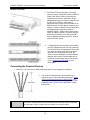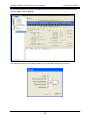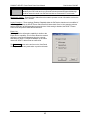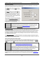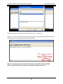
1
DPoE™ 1GIG™ Power Patch Panel User Manual Copyright © 2008 PANDUIT Corp. All rights reserved. No part of this book shall be reproduced, stored in a retrieval system, or transmitted by any means, electronic, mechanical, photocopying, recording or otherwise, without written permission from PANDUIT. No patent liability is assumed with respect to the use of the information contained herein. Although every precaution has been taken in the preparation of this book, PANDUIT assumes no responsibility for errors or omissions. Neither is any liability assumed for damages resulting from the use of the information contained herein. Part # PN439F Published October 2008 PANDUIT® DPoE™ Power Patch Panel User Manual Part Number: PN439F SAFETY WARNING Always observe standard safety precautions during installation, operation and maintenance of this product. Read the installation instructions before connecting the unit to its power source. There are no user serviceable parts inside the unit. To avoid the possibility of electric shock, the user should not perform any adjustment, maintenance or repairs, or open unit. Do not work on the product or connect or disconnect cables during periods of lightning activity. Ultimate disposal of this product should be handled according to all national laws and regulations. WARRANTY Unless otherwise specified, all products presented in this user's guide are warranted against defects in material and workmanship for a period of one year from the date of sale to the initial purchaser. PANDUIT Corp. warrants that its firmware designed by PANDUIT Corp. for use with the product will execute its functions when properly installed in the product for one year from the date of sale to the initial purchaser. PANDUIT Corp. does not warrant that the operation of the product or the firmware will be uninterrupted or error-free. During the warranty period PANDUIT Corp. will, at its discretion, either repair or replace products that prove to be defective. For warranty service or repair, the product claimed to be defective must be returned to a service facility designated by PANDUIT Corp. Buyer shall prepay all the shipping charges to PANDUIT Corp. and if, in the opinion of PANDUIT Corp., the product is defective, PANDUIT Corp. shall pay shipping charges to return the product to Buyer. However, Buyer shall pay all shipping charges, duties and taxes for products returned to PANDUIT Corp. from another country. The products presented in this user's guide are not designed, intended, authorized or warranted to be suitable for use as components in systems used in any life support or critical applications, including but not limited to, any applications intended to support or sustain life, any medical applications, any systems used for commercial transportation or nuclear facilities or any other applications where product failure could lead to personal injury, death or catastrophic property damage. Accordingly, PANDUIT Corp. disclaims any and all liability arising out of the use of the products in any life support or critical application. If buyer uses the product in any life support or critical application, buyer, and not PANDUIT Corp, assumes full responsibility for such use. Further, PANDUIT Corp. reserves the right to refuse to service any product used in any life support or critical application, and disclaims any and all liability arising out of the PANDUIT’S service or refusal to service such product. The foregoing warranty shall not apply to defects resulting from, buyer-supplied firmware or unauthorized interfacing, modification or misuse of the product, operation outside of the environmental specifications for the product, or improper or inadequate site preparation or maintenance by Buyer. NO OTHER WARRANTY IS EXPRESSED OR IMPLIED. PANDUIT CORP. SPECIFICALLY DISCLAIMS THE IMPLIED WARRANTIES OF MERCHANTABILITY AND FITNESS FOR A PARTICULAR PURPOSE. THE REMEDIES PROVIDED HEREIN ARE BUYER'S SOLE AND EXCLUSIVE REMEDIES. PANDUIT CORP. SHALL NOT BE LIABLE FOR ANY DIRECT, INDIRECT, SPECIAL, INCIDENTAL OR CONSEQUENTIAL DAMAGES, WHETHER BASED ON CONTRACT, TORT OR OTHER LEGAL THEORY. Unless otherwise specified by PANDUIT Corp., opening of this product by unauthorized personnel will void this warranty. TRADEMARKS ™ DPoE and Ultimate ID are trademarks of PANDUIT Corp. All other trademarks are the property of their respective owners. 1 PANDUIT® DPoE™ Power Patch Panel User Manual Part Number: PN439F TABLE OF CONTENTS SAFETY WARNING........................................................................................................ 1 WARRANTY ................................................................................................................... 1 TRADEMARKS ............................................................................................................... 1 OVERVIEW ..................................................................................................................... 5 Features and Benefits ............................................................................................... 6 INSTALLATION .............................................................................................................. 8 Package Contents...................................................................................................... 8 Panel Mounting Procedure ..................................................................................... 10 Rack Mounting Instructions ................................................................................ 10 Grounding Requirements ................................................................................... 10 Network Connection ........................................................................................... 11 Connecting the Powered Devices .......................................................................... 11 Power Requirements ............................................................................................... 12 Powering Up the DPoE™ Power Patch Panel ....................................................... 13 OPERATION ................................................................................................................. 15 LED Indicators ......................................................................................................... 15 DPoE™ ELEMENT MANAGER SOFTWARE .............................................................. 17 Hardware and Software Requirements .................................................................. 17 Installing the DPoE™ Element Manager Software ................................................ 18 Connecting the DPoE™ Element Manager Host Computer to the DPoE™ Power Patch Panel .............................................................................................................. 19 DPoE™ Element Manager Operation ..................................................................... 19 Graphical User Interface ..................................................................................... 20 Additions or Changes to UserName/Password................................................... 21 Panel Discovery.................................................................................................. 22 Subnet Search .......................................................................................... 23 IP Range Search ....................................................................................... 25 Provisioning the Panel ........................................................................................ 26 Administering Port and Panel-level Information .................................................. 30 Edit Panel Information ............................................................................... 31 Active Port Indicator .................................................................................. 32 Panel IP Address .............................................................................. 33 Panel Attributes ................................................................................. 33 SNMP Settings .................................................................................. 34 SNMP Retry ...................................................................................... 34 SNMP Access and Security ................................................................................ 36 Trap Settings ..................................................................................... 36 Copy/Paste/Delete Panel Information ....................................................... 37 Backup of Panel and Port Information ....................................................... 38 Restoring Device and Port Information ..................................................... 39 View Port Information ................................................................................ 40 Edit Port Information ......................................................................... 41 Export Log ................................................................................................. 43 View Entire Log ......................................................................................... 44 Filter Log Messages .................................................................................. 45 2 PANDUIT® DPoE™ Power Patch Panel User Manual Part Number: PN439F Export Log ................................................................................................. 45 Clear Log................................................................................................... 45 Refresh the Network ........................................................................................... 46 Administering E-mail Settings ............................................................................. 46 Search for Specific Panel(s) or Port(s) ............................................................... 47 DPoE™ Element Manager Log Messages ......................................................... 50 Miscellaneous Settings ....................................................................................... 51 DPoE™ Power Patch Panel Firmware Update ................................................... 51 Detailed Description of the Firmware Update ..................................................... 52 Exiting the DPoE™Element Manager ................................................................. 53 Resetting the DPoE™ 1Gb Power Patch Panel ................................................. 54 APPENDIX 1 – BASIC TROUBLESHOOTING ............................................................ 55 APPENDIX 2 - TFTP SERVER INSTALL ..................................................................... 56 TECHNICAL SPECIFICATIONS................................................................................... 60 GLOSSARY .................................................................................................................. 61 Figures Figure 1: DPoE™ Power Patch Panel (Front View) ........................................................ 5 Figure 2: DPoE™ Power Patch Panel (Rear View) ......................................................... 6 Figure 3: System-Level Opening Screen....................................................................... 20 Figure 4: View Panel Screen ......................................................................................... 30 Figure 5 : View Device Screen – SNMP Settings .......................................................... 31 Figure 6: Edit Panel Screen .......................................................................................... 31 Figure 7: Active Port Indicator Screen ........................................................................... 32 Figure 8: View All Ports Screen ..................................................................................... 41 Figure 9: View Individual Port Screen ........................................................................... 42 Figure 10: View Message Log Screen........................................................................... 44 Figure 11: View Message Log Filter Parameter Screen ................................................ 45 List of Tables Table 1: Package Contents ............................................................................................. 8 Table 2: Power Supplies Available from PANDUIT ......................................................... 9 Table 3: Recommended Strain Relief Bars Available from PANDUIT ............................. 9 Table 4: Color-Coded Wire Positions for 802.3af-2003 Complaint Devices .................. 12 Table 5: DPoE™ Power Patch Panel Power Up Sequence .......................................... 14 Table 6: Panel Status LED Indications .......................................................................... 15 Table 7: Port Status LED Indications............................................................................. 15 Table 8: Network Status LED Indications ...................................................................... 16 Table 9: PC Minimum Requirements for DPoE™ Element Manager ............................ 17 Table 10: SNMPv3 Defaults and Access....................................................................... 36 Table 11: DPoE™ Element Manager Log Messages .................................................... 50 Table 12: DPoE™ Power Patch Panel Firmware Update LED Status .......................... 53 Table 13: DPoE™ 1Gb Power Patch Panel Hardware Reset Sequence ...................... 54 Table 14: Basic Troubleshooting Guide ........................................................................ 55 3 PANDUIT® DPoE™ Power Patch Panel User Manual 4 Part Number: PN439F PANDUIT® DPoE™ Power Patch Panel User Manual Part Number: PN439F OVERVIEW The DPoE™ Power Patch Panel provides a reliable and cost-effective solution for Power over Ethernet (PoE) applications, complaint with the IEEE 802.3af-2003 specifications. Each DPoE™ Power Patch Panel allows centralized powering of up to 24 devices, such as Internet Protocol-based (IP) telephones, Network Security Cameras, or Wireless Devices, over the same cabling used to provide the Ethernet connectivity. By eliminating separate power connections to each of the devices, the DPoE™ Power Patch Panel provides a more cost-effective solution, particularly in cases where the devices are numerous or local powering is impractical. The DPoE™ Power Patch Panel is used to inject PoE power into an existing infrastructure without the need for a separate midspan power injector can which increase costs and wiring complexity, and affect performance. While the DPoE™ Power Patch Panel may be used as a standalone device, it can be configured and monitored from a centralized software application, the DPoE™ Element Manager. This management software application allows network operators to remotely perform routine maintenance and monitoring of any DPoE™ devices in their network. The DPoE™ Element Manager allows operators to graphically view and monitor DPoE™ device status, fault conditions and overall power consumption. In addition, the DPoE™ Element Manager allows the operator to designate power priority to individual ports. A Network Management System (NMS), such as HP Software, can use this pre-configured information from the DPoE™ Element Manager to guarantee mission-critical devices remain operational. DPoE™ Power Patch Panels cannot be used for analog or non-Ethernet devices. NOTE: Port number Panel Status LED Port Status LED (one per port) RJ-45 connector (one per port) 23 24 Figure 1: DPoE™ Power Patch Panel (Front View) 5 PANDUIT® DPoE™ Power Patch Panel User Manual Duplex capable Aand B-feed Power Connections Part Number: PN439F OUT management port and OUT Network Status LED Punchdown connections IN management port and IN Network Status LED Figure 2: DPoE™ Power Patch Panel (Rear View) Features and Benefits The following table highlights some of the capabilities of the DPoE™ Power Patch Panel along with the tangible benefit to the network operator. DPoE™ Power Patch Panel Feature Benefit Powers up to 24 devices from a centralized location By using PoE, a network operator can more costeffectively deliver power to PoE Powered Devices (PD) up to an aggregate 100m (328 ft.) channel length from the DPoE™ Power Patch Panel. Powering from a centralized location removes the need to power each device separately, eliminates the need for separate Uninterruptible Power Supply (UPS) for critical devices, and enables centralized power management by the network operator. Combining PoE Power with patch panel functionality The DPoE™ Power Patch Panel combines patching and power injection into a 1 RU-high package. This reduces rack space by at least 50% while providing easier installation, eliminating the need for patch cords between Power Hub and a non-powered patch panel configuration. IEEE 802.3af-2003 Compliant Many currently available PoE powering options are not standards-based, thus requiring coordination between each device’s power needs and the technical capabilities of the in-line powering unit. Each port on the DPoE™ Power Patch Panel can automatically detect and support the 802.3af-2003 standard or the legacy Cisco powering scheme. Full IEEE 802.3af power to all ports Each port on the DPoE™ Power Patch Panel is capable of delivering the full PoE power specified by the IEEE 802.3af-2003 standard (15.4 Watts at the PSE). 6 PANDUIT® DPoE™ Power Patch Panel User Manual Part Number: PN439F DPoE™ Power Patch Panel Feature Benefit Increased System Reliability through efficient thermal design The DPoE™ Power Patch Panel does not require the use of an internal fan. Fans can reduce the system reliability. Simultaneous support for the Cisco powering scheme along with the 802.3af2003 standard Any port on the DPoE™ Power Patch Panel can support the 802.3af-2003 standard or the legacy Cisco In-Line powering scheme. By supporting both methods on each port, the DPoE™ Power Patch Panel provides ultimate flexibility without the need for separate devices or power module adaptations for each powering scheme. Devices that do not require PoE powering may also be mixed in the same DPoE™ Power Patch Panel. Power Prioritization using the DPoE™ Element Manager In the event of a power lag or interruption a Network Management System (NMS) monitoring the DPoE™ Power Patch Panel can execute pre-established port priorities to ensure mission-critical ports on the network continue to receive PoE power as long as possible. Easier Local Management using visual prompts Multi-colored LEDs on the DPoE™ Power Patch Panel allow technicians to instantly know the status of each port. Additional LEDs indicate management and power midspan status. Ultimate ID labels on the front the system allow the technician to note the device number, the port number and wiring scheme information for both the Switch and Powered Device sides of the DPoE™ Power Patch Panel. Easier Remote Management using the bundled DPoE™ Element Manager The DPoE™ Element Manager allows network operators to easily view and manage a network of DPoE™ Power Patch Panels using the industry standard Simple Network Management Protocol (SNMP) to exchange management information between network devices. Easier Installation By eliminating the need for separate midspans and the associated need for patch cords, in a network-ready 1RU high package, The DPoE™ Power Patch Panel is fast and easy to install. 1 GbE data transmission rate. (10/100/1000) Beyond the current IEEE 802.3af-2003 standard the DPoE™ Power Patch Panel supports a 1 GbE data transmission rate. (10/100/1000) 7 PANDUIT® DPoE™ Power Patch Panel User Manual Part Number: PN439F INSTALLATION The DPoE™ Power Patch Panel requires a direct connection to a nominal -48 VDC supply. A power supply may be purchased separately from PANDUIT or other vendors (provided that exact specifications are fully met). Installation instructions for the individual power supply are included with that product. Package Contents Each DPoE™ Power Patch Panel is shipped in a box, which includes the following: Table 1: Package Contents Item Quantity DPoE™ Power Patch Panel(s) 1 Wiring Template Label 1 Quick Installation Instructions 1 DPoE™ Installation Worksheet 1 Metric and SAE screws 12 8 inch grounding strap 1 DPoE™ Support Tools CD-ROM containing: 1 Notes For use on the rear panel of the DPoE™ Power Patch Panel – Supports either EIA/TIA 568A or 568B wire positions. Installation requires six screws. One bag of six metric screws (M6x1.0x16) and one bag of six SAE screws (12-24x1/2”) are included. DPoE™ Element Manager software DPoE™ 1GIG™ Power Patch Panel Users Guide Release Notes Application Notes Installation Guides Power connector housing with wire leads 1 This wiring harness is used to connect the DPoE™ Power Patch Panel to -48 VDC power supply. Not used if the panel is powered by the DPoE™ Power Supply (PANDUIT part # DPOEPWRB120Y.) 10 Foot Power Harness 1 Used to connect -48V A-feed to a power supply. Butt splices 2 Two butt splices may be used to extend the 10 Foot Power Harness. (Should not exceed a total length of 35 feet). Verify the above contents arrived in good condition. If not, contact PANDUIT Technical Support. 8 PANDUIT® DPoE™ Power Patch Panel User Manual Part Number: PN439F Table 2: Power Supplies Available from PANDUIT PANDUIT Part # Description DPOEPWRB120Y 120 watt power supply, -48 volt output DPOEPWRCU Unmanaged power chassis - supports 3 rectifiers and optional Network Interface Card (NIC) DPOEPWRR500 500 watt rectifier for use in the DPOEPWRCU chassis DPOEPWRR1250 1250 watt rectifier for use in the DPOEPWRCU chassis CORD-A Power cord for Australia and Asia CORD-E Power cord for Europe CORD-S15 Power cord for North America CORD-J15 Power cord for Japan CORD-U Power cord for the U.K. Table 3: Recommended Strain Relief Bars Available from PANDUIT PANDUIT Part # Recommandations SRBCT: Cable strain relief bar with cable tie clips When using Standard TIA 19” rack systems, combine either bar with bracket kit (PANDUIT part # SRBBRKT) to provide adequate depth When using higher density 19” rack systems such as PANDUIT NetRack™ Rack Systems no additional brackets are neccessary When using higher density rack systems that have 23” mounting such as NetFrame® Rack System, combine with Panel Extender Brackets (PANDUIT part # PEB1) to adjust to 19” mounting space OR SRB19BLY: Cable strain relief bar w/ 2" extension off rack (Note: PAN-TY Cable Ties (PANDUIT part # PLT1.5M-C) for SRB19BLY are sold separately) Table 4: PANDUIT Corp. Contact Information PANDUIT Technical Support Fax: E-mail: For Installation Instructions in Local Languages and Technical Support http://www.panduit.com/Support/Software/index.htm Worldwide Subsidiaries and Sales Offices www.PANDUIT.com Latest Software Updates http://www.panduit.com/Support/Software/index.htm IMPORTANT: 1-708-444-6993 [email protected] The DPOE™ Installation Worksheet should be used to record pertinent information when installing DPoE™ Power Patch Panel(s), particularly if the DPoE™ Element Manager is monitoring the network (refer to Provisioning the Panel for more instruction on how this information will be entered in the DPoE™ Element Manager). The installer should complete this worksheet. 9 PANDUIT® DPoE™ Power Patch Panel User Manual Part Number: PN439F Panel Mounting Procedure WARNING: Only trained and qualified service personnel should install or service DPoE™ Power Patch Panels. Before installing or servicing DPoE™ Power Patch Panels or communication wiring, be aware of the hazards with the associated electrical circuitry. ATTENTION: Observe precautions for handling electrostatic sensitive electronic devices when installing this product. Ensure that you are properly grounded with a wrist strap or equivalent while making connections to the 110 punch down terminals on the rear of the product. Never make any connections to the 110 punch down terminals when power is being applied to the product. Rack Mounting Instructions 1. Record the MAC address, printed on a sticker on the back of the unit, by writing it in the space provided on the included Installation Worksheet (PANDUIT part # PN377). 2. Slip the Wiring Template Label over the rows of connectors on the back of the DPoE™ Power Patch Panel, making sure the proper wiring code is facing out and that the writing is not upside down. One side of the label indicates EIA/TIA 568A wiring, while the other side is EIA/TIA 568B wiring. Grounding Requirements 3. Using a screw from the SAE screw set, denoted by “01881-38 REV 2,” attach the green and yellow striped grounding strap to the panel via the unthreaded hole nearest the power connector. Next, install the panel into a grounded rack using the appropriate screw set provided to ensure proper grounding between the panel and the rack. Finally, attach the loose end of the grounding strap to the rack within the same position as the panel. PANDUIT structured ground kits for data center rack grounding can be used to properly ground PANDUIT® NetRack Rack Systems and racks from most other manufacturers. Record the rack space position on the Installation Worksheet. WARNING: The supplied screws are part of a grounding system to ensure that the DPoE™ Power Patch Panel is properly grounded to the rack. USE ONLY THE SUPPLIED SCREWS TO ATTACH THE PANEL TO THE RACK. 10 PANDUIT® DPoE™ Power Patch Panel User Manual Part Number: PN439F Network Connection 4. If the DPoE™ Element Manager is not being used to remotely manage the network of DPoE™ Power Patch Panels, skip to Connecting the Powered Devices below. Otherwise, using a standard patch cord (for example, PANDUIT part # UTPCH3 or UTPSP3), connect the IN management port on the back of the panel to an Ethernet switch. A DHCP Server must be on this network—unless the DPoE™ Power Patch Panel has already been configured for Static IP operation (DPoE™ Power Patch Panels expect DHCP as a factory default). The panel may also be directly connected to a PC with the DPoE™ Element Manager installed, but this PC must be setup as a DHCP Server.” 5. If multiple panels are being used in the network, the OUT management port from one panel may be connected to the IN management port on the next panel in a daisy chain fashion, as shown. Once all of the connections are made, the DPoE™ Element Manager or another Network Manager will be able to communicate with all the panels over this daisy chain of connections (refer to Provisioning the Panel for more information). Connecting the Powered Devices 6. Remove 1 inch (25.4 mm) of cable jacket being careful not to damage the conductors. 7. Fan out all four twisted pairs in the specified wiring sequence (refer to color-coded wiring positions in Table 4:Color-Coded Wire Positions for 802.3af-2003).The colors are also displayed on the Wiring Template Label (installed in step 2) on the back of the DPoE™ Power Patch Panel. NOTE: The DPoE™ Power Patch Panel can terminate most 22-24 AWG solid or stranded IWC wire with a .050” (1.27mm) max o.d. either PVC or Plenum rated. 11 PANDUIT® DPoE™ Power Patch Panel User Manual Part Number: PN439F Table 4: Color-Coded Wire Positions for 802.3af-2003 Complaint Devices Pin Outs EIA/TIA 568A Pin Outs EIA/TIA 568B 5 WHITE/BLUE 5 WHITE/BLUE 4 BLUE 4 BLUE 1 WHITE/GREEN 1 WHITE/ORANGE 2 GREEN 2 ORANGE 3 WHITE/ORANGE 3 WHITE/GREEN 6 ORANGE 6 GREEN 7 WHITE/BROWN 7 WHITE/BROWN 8 BROWN 8 BROWN 8. Lay conductors into the punchdown slots for the specified port using the correct wiring sequence. Cable jacket removal should be minimized to the extent possible. Conductor untwist should be within ½” (12.7 mm) of termination. WARNING: NEVER TOUCH UNINSULATED COMMUNICATIONS WIRING OR TERMINALS UNLESS THE COMMUNICATION LINE HAS BEEN DISCONNECTED AT THE NETWORK INTERFACE. NOTE: Never install wiring in a slot previously used for a larger gauge wire. 9. Using the punchdown tool (PANDUIT part # PDT110), punch down the connector into the punchdown slots on the back of the DPoE™ Power Patch Panel. NOTE: INSTALLATION ADVISORY: When using punchdown tool, set tool to “High” setting for optimum performance. Ensure that cabling to powered devices is protected from inductive coupling from nearby power cables and other sources. Ensure that powered devices are properly installed and grounded (according to manufacturer’s recommendations), and all the cabling and connections are isolated from external surges. Observe precautions for handling electrostatic sensitive electronic devices when installing this product. Ensure you are properly grounded with a wrist strap or equivalent, while making connections to the 110 punchdown terminals on the rear of the product. Never make any connections to the 110 punchdown terminals when power is applied to the product. NOTE: When installing cabling and making connections to the DPoE panel, follow all local standards, as well as the applicable TIA-942 standards and IEEE 802.3 (Ethernet) standards. 12 PANDUIT® DPoE™ Power Patch Panel User Manual Part Number: PN439F Power Requirements 10. If the panel is being powered by a DPoE™ Power Supply (refer to Table 2: Power Supplies Available from PANDUIT for a list of available powering options), skip to Powering Up the DPoE™ Power Patch Panel section below, since the DPoE™ Power Supply is equipped with a matched keyed power connector that will fit the power connector on the back of the panel. 11. If the panel is being supplied by a DPoE™ Power Chassis or a direct -48 VDC source, cut the 10-foot power harness to length then strip the ends of the leads to 5/16” (7.9 mm). Connect the stripped ends of the power harness into the DPoE™ Power Chassis. If the power harness is not long enough or the -48 VDC source requires a specific connector, strip the ends of the wire to the same strip length, being careful not to damage the conductors. 12. Using the two butt splices provided with the panel, and paying attention to the polarity of the supply voltage, crimp the power harness wires to the supply wires. A crimping tool, such as the PANDUIT part # CT-100, may be used. The provided butt splices (PANDUIT part # BSV14X) support 14-16 AWG solid or stranded wire. 13. Lightly tug on the butt spliced connections to verify that the butt splices are secure. WARNING: The power supply connections are polarized. The DPoE™ Power Panel will not function if power is wired improperly. The overall length of the power harness between the power supply and the DPoE™ Power Panel should not exceed 35 feet. NOTE: The included power harness has two wires for the A-feed power only (pins 1 & 2). The DPoE™ Power Patch Panel supports an optional redundant B-feed power option, but the terminals and wire leads are not attached to the power harness. Contact PANDUIT Technical Support for more information about connecting the redundant B-Feed Power. NOTE: Proper fuses need to be equipped when power DPoE™ devices. (Refer to installation sheet PN385 for appropriate DPoE™ Power System chassis fuse selection.) NOTE: Per IEEE 802.3af, ensure that the power supply provides a minimum of 1500V insulation between battery and chassis ground. 13 PANDUIT® DPoE™ Power Patch Panel User Manual Part Number: PN439F Powering Up the DPoE™ Power Patch Panel 14. Plug the connector into the back of the DPoE™ Patch Panel. 15. Once power is applied to the unit, the DPoE™ Power Patch Panel will go through a power up sequence. The following table describes the behavior of the unit as viewed from the front and the back. Table 5: DPoE™ Power Patch Panel Power Up Sequence Behavior as viewed from the back of the unit Behavior as viewed from the front of the unit Both network status LEDs will light amber for two seconds The panel status Light-Emitting Diode (LED) will light red for about 10 seconds. After that, a LED test sequence of the port status LEDs will take place. The port will light red from the center to the outside, then will flash green. At that point all will turn amber for a short time and will then turn off. If there is no cable connected to the IN management port (Step 4 above), both network status LEDs will turn off. If the Patch Panel is configured for Dynamic Host Control Protocol (DHCP) address assignment (default configuration) and a cable is NOT connected to the IN management port on the rear of the panel, the panel status LED will turn green. If the DPoE™ Power Patch Panel is configured for DHCP address assignment (default factory setting), the network status LED above the IN management port will stay amber and the network status LED above the OUT management port will turn off. This indicates that the panel is actively requesting address information from the network. Once this information is received (this could take up to a minute), the network status LED above the IN management port will turn on or start flashing green as data is transmitted and received. If the DPoE™ Power Patch Panel is configured for DHCP address assignment (default factory setting), the panel status LED will flash amber. This indicates that the panel is actively requesting address information from the network. Once this information is received (this could take up to a minute), the panel status LED will flash green (refer to Figure 1: DPoE™ Power Patch Panel (Front View) and Figure 2: DPoE™ Power Patch Panel (Rear View) for a graphical view of the LEDs on the DPoE™ Power Patch Panel). If the panel is set to static IP addressing rather than DHCP, the network status LED above the IN management port will turn on or start flashing green as data is transmitted and received. If the panel is set to static IP addressing rather than DHCP, the panel status LED will flash green and continue flashing as long as power is applied to the unit. NOTE: For any troubleshooting issues, refer to APPENDIX 1 – BASIC TROUBLESHOOTING at the back of this user’s guide. 14 PANDUIT® DPoE™ Power Patch Panel User Manual Part Number: PN439F OPERATION LED Indicators The DPoE™ Power Patch Panel displays system and port status through the use of LEDs on the front and rear of each panel. There is one panel status LED on the front left of the panel, 24 individual port status LEDs above each port, and two network status LEDs on the rear of the unit. These LEDs enable the technician to see at a glance if either the ports or the panel itself is in alarm (refer to Figure 1: DPoE™ Power Patch Panel (Front View) and Figure 2: DPoE™ Power Patch Panel (Rear View) for a graphical view of the LEDs on the DPoE™ Power Patch Panel). The following tables do not include the LED status during powering up the unit (refer to Table 5: DPoE™ Power Patch Panel Power Up Sequence for more information on the LED indications during power up). Table 6: Panel Status LED Indications LED Color Panel LED Status Description Status of Power Ports Off Off No Power is being supplied to the panel. Power is NOT being delivered to the ports on the panel. Green Flashing System operating normally. Power may be delivered to the ports on the panel, as configured. Amber Solid Out of voltage range condition. Less than -46 VDC or more than -57 VDC is being supplied to the panel. Power is NOT being delivered to any ports on the panel. Red Solid The main processor on the panel is NOT operating properly and power may NOT be delivered to any ports on the panel. Power may or may NOT be delivered to any ports on the panel, as configured. Table 7: Port Status LED Indications LED Color Port LED Status Description Status of Power Ports Off Off No Powered Device (PD) is connected to this particular port on the panel. Power is NOT being delivered down this port on the panel. Amber Solid The panel is determining the PD's power requirements. This occurs for 5 seconds after the PD is connected. Power is NOT being delivered to this port on the panel. Green Solid Port is providing power. Power is being delivered to this port on the panel. 15 PANDUIT® DPoE™ Power Patch Panel User Manual Part Number: PN439F LED Color Port LED Status Description Status of Power Ports Red Solid The system has failed to determine the PD power requirements for this port. Perhaps this PD is not an 802.3af-2003 compliant or Cisco legacy power device. Power is NOT being delivered to this port on the panel. Also, pins (1,2) & (3,6) of a connected non-powered device such as a PC may be terminated in such a way that the power patch panel attempts to detect it as a PD. The DPoE™ Element Manager may be used to turn detection off to this port so no further checks occur (see DPoE™ Element Manager section). The LED will extinguish. This may also be an indication of a short in the wiring. The connections at both ends of the horizontal cabling should be checked to ensure proper wiring has been followed. Table 8: Network Status LED Indications LED Color Network LED Status Description Off Off No connection to the management system. If the system is otherwise operating normally and an Ethernet 10/100 cable is connected, this could be an issue with the panel's management interface. Green Flashing The management link on the DPoE™ Power Patch Panel is configured correctly and communication messages are currently being processed. Normal operation. Green Solid The management link on the DPoE™ Power Patch Panel is configured correctly, but no communication messages are currently being processed (i.e., the link is idle). Normal operation. Amber Solid The panel is currently trying to acquire DHCP address information from the network. If this persists for more than a minute or two, the daisy chain of connections between multiple panels may be incorrect or there are problems at the DHCP server. 16 Notes PANDUIT® DPoE™ Power Patch Panel User Manual Part Number: PN439F DPoE™ ELEMENT MANAGER SOFTWARE The DPoE™ Element Manager software is used to remotely control, configure and monitor a DPoE™ Power Patch Panel within a network. Once installed on a shared or dedicated Windows-based Personal Computer (PC), the DPoE™ Element Manager can be used to manage an entire network of DPoE™ devices. The DPoE™ Element Manager is on a CD-ROM included with the DPoE™ Power Patch Panel. The DPoE™ Power Patch Panel does not require the DPoE™ Element Manager software to operate. Installed power patch panels will source PoE power without the software. Software provides an optional enhanced level of remote management, monitoring and maintenance for a single device or an entire network of DPoE™ devices. (Latest updates at http://www.panduit.com/Support/Software/index.htm) NOTE: Hardware and Software Requirements Table 9: PC Minimum Requirements for DPoE™ Element Manager Hardware Processor PC with 300 megahertz (MHz) Pentium®-class processor or equivalent RAM 128 MB of RAM, 256 MB recommended Hard Disk Space 45 MB of available hard disk space Network Access 10/100 Ethernet card CD-ROM Drive Software Operating System Support Applications Display Settings Any of the following: Windows® Vista™ Windows® XP Professional (Service Pack 1 or later), Windows XP Home Edition (Service Pack 1 or later), Windows 2000 (Service Pack 4 for Windows 2000). 1.) 2.) Microsoft .NET Framework 1.1 Redistributable or later Microsoft Data Access Component version 2.7 or later (See notes below) For XP Professional or Home Edition: Settings: 1024x768 or larger Color Quality: Medium (16-bit) or higher Advanced: Normal Size Fonts (96dpi) REQUIRED Appearance: Font Size Normal REQUIRED For Windows 2000: 1024x768x32K colors Small Fonts REQUIRED (Normal 96dpi) NOTE: If Microsoft .NET Framework version 1.1 or Microsoft Data Access Components is not currently installed on the PC, the user will be prompted to install these software packages first before installing the DPoE™ Element Manager. The DPoE™ Element Manager will not operate correctly without these two support applications being installed on the same PC. Microsoft .NET Framework cannot currently be installed on 64-bit computers. 17 PANDUIT® DPoE™ Power Patch Panel User Manual Part Number: PN439F Installing the DPoE™ Element Manager Software The DPoE™ Element Manager is installed by running the setup program on the DPoE™ Power Patch Panel Support Tools CD-ROM, included with the DPoE™ Power Patch Panel. Once the CD-ROM is placed in the personal computer's CD-ROM drive, the setup program will automatically run and will give the user the choice to install the DPoE™ Element Manager software or choose from other selections. When selected, the installation software will first verify the necessary support software is available on the computer or will prompt the user to determine whether these packages should be installed along with the DPoE™ Element Manager (refer to Table 9: PC Minimum Requirements for DPoE™ Element Manager for more information). NOTE: If the CD does not autorun, browse the root directory of the CD and double-click on the file “Launch.exe”. Once all required support software is installed, the installation screen will be displayed. For security purposes, the network operator will then be given the opportunity to restrict the DPoE™ Element Manager to the administrator UserName only (default) or whether other users of this PC can access it. Once this selection is made, the installation process completes in only a few minutes. After the DPoE™ Element Manager installation completes, exit the DPoE™ Power Patch Panel Support Tools CD, remove the CD-ROM from the CD-ROM drive, and store it in a safe place. Next, launch the DPoE™ Element Manager application via the icon on the desktop. The splash screen will appear. When prompted, UserName: administrator, Password: Panduit (password is case sensitive and should be changed from this default) NOTE: The DPoE™ Power Patch Panel Support Tools CD-ROM also includes the option to uninstall the DPoE™ Element Manager. Critical updates to the support programs may occasionally come from Microsoft Corporation. The Windows Update option from the PC’s START Menu can be used to periodically check for such updates. 18 PANDUIT® DPoE™ Power Patch Panel User Manual Part Number: PN439F Connecting the DPoE™ Element Manager Host Computer to the DPoE™ Power Patch Panel The computer that hosts the DPoE™ Element Manager can either be directly connected to the DPoE™ Power Patch Panel or connected through the Ethernet network. If the PC is directly connected to the DPoE™ Power Patch Panel, the PC must either be setup as a DHCP Server, or the panel must be setup for a static IP address. If the PC is connected to the DPoE™ Power Patch Panel through an Ethernet network, the network must have a DHCP Server on it, or the panel must be setup for a static IP address. Once the PC is logically connected to the first DPoE™ Power Patch Panel, successive panels may be daisy chained to the previous panel by connecting the “OUT” management port on that panel to the “IN” port on the next panel. These connections are made via a RJ-45 standard patch cord (refer to the Installation section for more information on daisy chaining the panels together). NOTE: There is no need to connect the “OUT” management port on the last DPoE™ Power Patch Panel in the daisy chain to anything. IMPORTANT: Directly connecting a PC to the panel will either require the PC to be setup as a DHCP Server or require the DPoE™ Power Patch Panel to be setup for static IP addressing. The panel factory default setting is DHCP addressing. If a panel is changed to static IP addressing, make sure the static IP address is recorded; no communication to the DPoE™ Power Patch Panel can be done without this address. Never connect a PC setup as a DHCP Server to an Ethernet network that already has a DHCP Server on it. DPoE™ Element Manager Operation Once the DPoE™ Element Manager is successfully installed, access the program using the shortcut installed on the desktop by the DPoE™ Element Manager installation software. (The program is stored in the PANDUIT directory under the programs directory and can also be accessed through the START menu.) After displaying the version number of the DPoE™ Element Manager, the user is prompted for a UserName and password. NOTE: When the management system is first installed, the default UserName is administrator with a password of Panduit (notice the capital “P”). Passwords are case-sensitive. This default UserName and Password should be changed once the user is familiar with the DPoE™ Element Manager software (refer to Additions or Changes to UserName/Password for more information). 19 PANDUIT® DPoE™ Power Patch Panel User Manual Part Number: PN439F Graphical User Interface The DPoE™ Element Manager has an easy-to-use graphical user interface with pull-down menus and tool bars, which make configuring and provisioning the network easy. When the DPoE™ Element Manager software is opened, the following system-level opening screen appears. Pull-down menus Tool bar List View of the ™ DPoE device area Tree View of Network Area Message Log area Tool bar for Message Log Online indicator Figure 3: System-Level Opening Screen The system-level opening screen is broken into three areas: the Tree View of the Network area, the List View of the DPoE™ Power Patch Panels and the Message Log area. By working in each of these three areas, the network operator can easily monitor the overall status of the DPoE™ Power Patch Panel network, the status of individual patch panels, or the status of individual ports on individual panels. Likewise, configuration changes can be made at the network, panel or port level. The Tree View of the Network area provides a hierarchical display of each patch panel within the network using the configurable names assigned by the network operator. Multiple patch panels physically wired into a single rack are grouped on the screen under the configurable name of that rack. Using the computer mouse, the operator can select a specific rack, and the display will expand to show the individuals panels within that rack. When the operator selects an individual rack, the DPoE™ Element Manager automatically displays the information for each DPoE™ Power Patch Panel within that rack in the List View area (top right). Likewise, all log messages relating to that rack are automatically displayed in the Message Log area (bottom right). These messages indicate any conditions with the rack itself, the DPoE™ Power Patch Panels on that rack or individual ports on individual panels within that rack. 20 PANDUIT® DPoE™ Power Patch Panel User Manual Part Number: PN439F If the operator selects an individual panel from the Tree View of the network area, a second screen, which overlays the Message Log and List View areas, allows the operator to configure and monitor a specific DPoE™ Power Patch Panel (refer to Figure 4: View Panel Screen for more information). In addition to the three areas on the system-level opening screen, the DPoE™ Element Manager provides the following conveniences on this system-level opening screen. Tool Bars – The most frequently performed actions are assigned buttons on the two tool bars to speed with assigning ports and panels, adding users to the management system, filtering incoming messages for trouble isolation etc. Pull-Down Menus – All functions available through the tool bars are also available through the pull-down menus, but, in addition, network-wide functions, such as copying panel information from an existing panel to a new panel is also available. Online Indicator – This real-time display indicates the communication status between the DPoE™ Element Manager and the DPoE™ Power Patch Panels. Additions or Changes to UserName/Password By adding additional UserNames to the DPoE™ Element Manager, the network operator can allow access to the system, via the DPoE™ Element Manager, by other users without the need for sharing a single UserName/Password among multiple users. The Users option under the Tools pull-down menu provides an easy mechanism to add new or modify UserNames. There is also a button ( ) on the top tool bar on the system-level opening screen to perform this task. By clicking on the Add button, the network operator can create new UserNames and Passwords for use the system. A free-form Description field is also available. Maintenance of UserNames is done by first clicking an existing Username, then clicking on either the Remove button to delete that UserName or the Properties button to have the following screen appear. After any changes are made, use the Close button to return to the system-level opening screen. NOTE: Passwords are case-sensitive. Users must enter the password exactly as the network operator assigned it. A user cannot delete a currently active UserName. 21 PANDUIT® DPoE™ Power Patch Panel User Manual Part Number: PN439F Panel Discovery Once the DPoE™ Element Manager is connected into the network, the “Discover” capability can be used to "find" the deployed DPoE™ Power Patch Panels (refer to Connecting the DPoE™ Element Manager Host Computer to the Host DPoE™ Power Patch Panel for more information). The DPoE™ Element Manager initiates messages into the control network and requests responses from any panels that see this message. NOTE: Unless the DPoE™ Power Patch Panel has been configured during installation using the DPoE™ Element Manager, this “Discover” capability will only receive the configuration and existence of the DPoE™ Power Patch panels themselves. The network operator will still need to enter port and rack information, such as which racks the panels are wired into and where in each rack the panel is physically mounted. (The DPoE™ Power Patch Panel Installation Worksheet included with the product can be used to collect this information during installation.) When installing multiple DPoE™ devices simultaneously, it is very important to record the MAC address for each panel. Since multiple panels will return the same factory default settings to the “Discover” capability, the MAC address, which is written on a sticker on the back of each DPoE™ Power Patch Panel, is unique and will allow the network operator to distinguish one panel from another (refer to Installation for more information on installing the DPoE™ Power Patch Panels). The Discover option under the Devices pull-down menu will perform this task or click the button ( the top tool bar on the system-level opening screen. ) on The network operator can set the Discover capability to search a specific subnetwork for panels or search across a range of IP addresses. If appropriate, you should take into account the VLAN IP address of the switch port when discovering the panel/power midspan. The two leftmost buttons on this Discover Devices window are used to select which type of Discover to initiate. By selecting the top button, the top half of the screen is then used to request a subnet search. 22 PANDUIT® DPoE™ Power Patch Panel User Manual Part Number: PN439F Subnet Search After selecting a Subnet option, the Add, Edit, and Remove buttons become active and give the network operator a chance to enter or modify the subnet information in the DPoE™ Element Manager prior to starting the Subnet search. When Add is selected, the Subnet dialog box will open. The network operator can then add the desired Subnet, Netmask, SNMP version, SNMP write community along with the Administrative Username and Password. Once the desired information is entered the network operator can select OK or Cancel. IMPORTANT: SNMP Community fields allow SNMP messages to be exchanged between the DPoE™ Element Manager and the DPoE™ Power Patch Panels. For security reasons, these fields should be changed from their defaults. Care should be taken, however, as the SNMP Community fields are case-sensitive and will read inadvertently mistyped spaces or characters. In addition, the default SNMP Version used for communication with the DPoE™ Power Patch Panel is SNMP v2c. If you change this to SNMP v3, you will need to change the “SNMP Version” setting for the subnet discovery to be successful. 23 PANDUIT® DPoE™ Power Patch Panel User Manual Once any subnetwork changes are entered (if necessary), check ( click the Start button. Part Number: PN439F ) those subnets to be searched and Check subnets to be searched Select Start to begin search When Start is selected the Scanning in progress dialog box will open showing the Subnet that is being scanned. 24 PANDUIT® DPoE™ Power Patch Panel User Manual Part Number: PN439F IP Range Search By selecting the bottom button on the Discover Devices screen, the bottom half of the screen is then used to request an IP range search as part of the Discover Capability. Select bottom button for Discovery By IP Address Select SNMP version, Starting and Ending IP address range, and provide username and passwords. Select Start to initiate the Discovery process. After entering the Starting IP Address, Ending IP Address, and SNMP Write Community, the Start button will initiate the Discover capability. Whether a subnet search or an IP range search was conducted, the discovered DPoE™ Power Patch Panel information will be populated in the DPoE™ Element Manager. TIP: In addition to the Discover capability, the DPoE™ Element Manager also supports a Refresh capability, which collects the information stored in each Patch Panel and verifies that it is consistent with the information in the DPoE™ Element Manager (refer to Refresh the Network for more information). 25 PANDUIT® DPoE™ Power Patch Panel User Manual Part Number: PN439F Provisioning the Panel The DPoE™ Element Manager has the capability to discover all of the DPoE™ Power Patch Panels in the network and display them in a format where the panels are grouped by their host racks based on the information entered into the panels during the provisioning process. These are called Panel Attributes. Individually identifying each panel and entering its specific attributes into the DPoE™ Element Manager is an integral part of the provisioning activity. Loading this information into the DPoE™ Element Manager enables it, as well as Network Management Software to be used in an effective working manner. It is highly recommended that the Network Administrator invest the effort to provision the DPoE™ device in the following manner: 1. During the installation of each DPoE™ Power Patch Panel, it is important to record the MAC address. This is required because it is the only unique identification of the DPoE™ Power Patch Panel once it is placed into your network. An installation worksheet is provided to record this and other important information. A bar code of the MAC is also provided that allows a bar code reader to record this information automatically. The MAC and bar code for the MAC are found on the rear of the DPoE™ Power Patch Panel near the management port. 2. Once the DPoE™ Power Patch Panel is connected to the network and power is applied, the DPoE™ Power Patch Panel will need to obtain an IP address. a. The DPoE™ Power Patch Panel can obtain an IP address via Dynamic Host Configuration Protocol (DHCP). This could take 1-2 minutes depending on your network and DHCP server settings. b. Or the DPoE™ Power Patch Panel can be set to a static IP address. In order to set the device to a static IP address, you will need the following information: 1. The desired static IP Address for the DPoE™ Power Patch Panel. 2. The desired Subnet Mask for the device. 3. The IP address of the desired Gateway for the device. Once this information is entered, select “Save” and the new settings will be saved to the device and the device will respond to those new settings. 26 PANDUIT® DPoE™ Power Patch Panel User Manual NOTE: Part Number: PN439F If the computer running the DPoE™ Element Manager is not in the subnet for the new IP address and cannot communicate with it, you will receive a timeout message similar to the one below: In order to correct this you will need to place the computer in the appropriate subnet, or correct the network settings of device to the proper setting. If you can no longer communicate with the device, see the section on Device IP Address for instructions on how to set the device to the default network settings. (Refer to Panel IP Address for more information.) Occasionally, when retrieving information for the panel/power midspan, the DPoE™ Element Manager may show a message indicating an “SNMP Agent Error”. If this occurs, retry the operation. If this repeats, it may be the indication of a slow network or a large number of concurrent operations, in which case you may have to increase the timeout setting of the DPoE™ Element Manager (located under the “Tools” section of the application). If the panel/power midspan continues to fail to respond, there may be a problem with the network connection itself. The DPoE™ Element Manager reflects physical location information and power status based on the last time this information was refreshed. In order to work with the latest physical location information and power status, you should refresh the panel/power midspan information using the Refresh icon on the Element Manager before making any modifications. When the IP address of the panel/power midspan is first assigned or is changed, you may see the message “The IP address has changed. Do you want to commit this (yes/no)?” when you are discovering the panel(s)/power midspan(s) in your network. Please select “yes”. Once this change is committed, you will not see this message again. When using the DPoE™ Element Manager to change the network settings of the panel/power midspan, and you go from DHCP to static or static to DHCP, you will lose communication with the panel/power midspan until the panel/power midspan is placed into a network that supports the new settings or your PC is placed into the new subnet. This is expected behavior. 3. Using the Discover capability of the DPoE™ Element Manager, search the subnet where the DPoE™ Power Patch Panels have been installed. 4. When the DPoE™ Power Patch Panels are discovered they will appear in a table as shown below: 27 PANDUIT® DPoE™ Power Patch Panel User Manual Part Number: PN439F 5. The table contains the MAC and IP address of the all of the discovered DPoE™ devices. The message log will include the MAC and IP address of the newly discovered device(s). The MAC Address can now be used to associate the discovered device with the information contained on the installation worksheet, and the Panel Attributes can now be entered. 6. Double-click on the row in the table containing the first newly discovered panel. After the panel information is gathered from the panel, the View Panel Screen will open and will look like this: Visual display of front panel Messages specific to this panel Tool Bar 7. Select the Edit DPoE™ device Info and the following form will open. This is where the DPoE™ Panel Attributes can be entered. 28 PANDUIT® DPoE™ Power Patch Panel User Manual Part Number: PN439F The DPoE™ Power Patch Panel name, rack name, rack space position, and contact name should be entered here like the previous example. The DPoE™ Element Manager will create a rack with that name, and any device that has the same rack name will be grouped under that rack. This screen also includes a place to record the name and location information of the power system for this DPoE™ Power Patch Panel. Note that the Panel Physical Location entry line allows 1024 characters of information to be entered, which includes additional physical and geographic information for this DPoE™ Power Patch Panel. Fill out per the example shown on right. Click the OK button and the Device Physical Location information will be added to the device attributes field. 8. Once all of the desired information is entered into the Panel Attributes field, click the Save button and this information will be saved. The panel and the rack images will be shown in the DPoE™ Element Manager Tree View of the Network Area associated with the designated name. 9. Other newly discovered panels can be provisioned by copying the Panel Attributes from this device, and making changes where needed for the new rack names, rack positions, device name, etc. This can be done by selecting the table row with the last provisioned DPoE™ device, right clicking, and choosing “Copy Panel”. Select the next panel to be provisioned by highlighting the row of the panel, right clicking, and choosing “Paste Panel." All of the Panel Attributes will be applied to the new device. Select “Edit Panel” and edit Panel Attributes and make the appropriate modifications. 29 PANDUIT® DPoE™ Power Patch Panel User Manual Part Number: PN439F 10. The previous step should be repeated for each panel in the network until all the panels have been provisioned. Once this is done, the DPoE™ Element Manager can easily manage all of the powered panels using the more intuitive physical location information that is stored in each panel. Administering Port and Panel-level Information The DPoE™ Element Manager makes it easy to administer the deployed network of DPoE™ Power Patch Panels. When a specific panel is selected in the Tree Level View of the Network on the systemlevel opening screen, the DPoE™ Element Manager automatically retrieves the latest power and LED information from the selected panel and displays on the View Panel Screen (refer to Table 6: Panel Status LED Indications, Table 7: Port Status LED Indications and Table 8: Network Status LED Indications for information on the LED Indicators). Visual display of front panel Messages specific to this panel Tool Bar Figure 4: View Panel Screen The top portion of the panel-level opening window provides a view of the DPoE™ Power Patch Panel, complete with the current LED status, IP address, rack name and rack location. The information on this screen can be edited by selecting the Edit Panel Info… button on the right side tool bar. 30 PANDUIT® DPoE™ Power Patch Panel User Manual Part Number: PN439F Figure 5 : View Device Screen – SNMP Settings The second tab on this screen allows user to view the SNMP information currently set for this device. This screen cannot be used to modify the configuration SNMP information. The SNMP configuration can be edited selecting the Edit Panel Info… button on the right side tool bar. Edit Panel Information In addition to the Edit Panel Info button on the tool bar, the Edit Panel option under the Devices pull-down menu provides an easy mechanism to perform this task. Figure 6: Edit Panel Screen This screen will allow the network operator to change the panel IP address, the panel attributes, the SNMP setting, or the trap settings. After any changes are made, be sure to click on the Save button to store the information and transmit it to the DPoE™ Power Patch Panel. 31 PANDUIT® DPoE™ Power Patch Panel User Manual Part Number: PN439F Active Port Indicator By clicking on any device port, its status information will be displayed and the selected port will be highlighted with a yellow flashing indicator on the EMS screen. When the select device is displayed you can click on a port (for this example port 5) and the selected port will highlight with a flashing yellow indicator. You will receive a dialog box on screen stating that the EMS is obtaining the latest information for the selected port. The port information will be displayed (for this example port 5) and the selected port will continue to be highlighted with the flashing yellow indication. Figure 7: Active Port Indicator Screen The Port information and yellow indicator will remain until another port is selected or you navigate to another screen view in the EMS. 32 PANDUIT® DPoE™ Power Patch Panel User Manual Part Number: PN439F Panel IP Address The DPoE™ Power Patch Panels come with a factory setting of DHCP address assignment. After the panel is connected to the DPoE™ Element Manager, the network administrator may change this setting by adding an IP address & Subnet Mask, if desired, to be consistent with the rest of his/her network. The Gateway field is the IP address of a gateway. If the DPoE™ Element Manager and the DPoE™ Power Patch Panels are on different networks or if the Simple Mail Transfer Protocol (SMTP) server is on a different network from the panel, the panel will send those messages to the gateway IP address specified. NOTE: The DPoE™ Power Patch Panel supports either static IP addressing or DHCP address selection. Panel Attributes This portion of the screen can be used to set the Panel Name, Rack Name, Rack Space Position, Panel Physical Location, and Power Supply Location. These fields are freeform and, while these fields will not change the operation of the DPoE™ Element Manager, they allow the DPoE™ Element Manager to present the panel and rack information in a user-friendly format. For example, with these fields set, panels in the same rack will be grouped together in the Tree View of the Network area on the systemlevel opening screen. Likewise, panels wired in a single rack will be displayed consistent with the value in the Rack Space Position field (refer to Provisioning the Panel for more information). Once these values are set in the DPoE™ Element Manager, this information will be transmitted and stored in the DPoE™ Power Patch Panels. Two additional fields are available on this screen and affect the operation of the panel. The first field, the Power Threshold, allows the network operator to configure the available power for this panel as a percentage of the maximum power the panel can support. For example, although the panel can support 480 watts, panels that use external power supplies, rather than a direct 48-volt input, are not normally capable of supplying 480 watts of power. Therefore, the Power Threshold for this panel might be set at 30%. And the Power Warning Threshold, which tells the panel when to send an alarm messages, might be set at 10%, so that the panel starts alarming when it reaches 90% of this particular panel's maximum (refer to DPoE™ Element Manager Log Messages for more information on Power Warning Threshold). The Enable Trap is a checkbox ( power alarms. ) to quickly turn on/off an individual panel’s reporting of threshold 33 PANDUIT® DPoE™ Power Patch Panel User Manual Part Number: PN439F SNMP Settings The system defaults to “public” for the SNMP Read Community and “private” for the SNMP Write Community. The SNMP Version Support can be selected to include v1/v2c/v3 or v1/v2c or v3 There is an SNMPv3 button within the SNMP settings section. Selecting this button will bring up the SNMPv3 dialog box. This dialog box allows the user to enter the Administrative Username, Authentication Password and (optionally) the Encryption Password in support of SNMPv3. IMPORTANT: The SNMP Community fields are case-sensitive and allow SNMP messages to be exchanged between the DPoE™ Element Manager and the DPoE™ Power Patch Panels. FOR SECURITY REASONS, THESE FIELDS SHOULD BE CHANGED FROM THEIR DEFAULTS. SNMP Retry While running the DPOE™ Element Manager Software you may receive a timeout message: In certain network conditions you may want to select the number of times a SNMP message retry occurs prior to receiving this Timeout error message. The SNMP Retry function enables a choice of the amount of times the SNMP message is retried. 34 PANDUIT® DPoE™ Power Patch Panel User Manual Part Number: PN439F Once a device has been discovered, the settings selections can be made from the pull down menu by choosing Tools, and then Settings. The Settings pop-up screen will appear, allowing you to set SNMP retries from 0 to 9 times. 35 PANDUIT® DPoE™ Power Patch Panel User Manual Part Number: PN439F SNMP Access and Security The security for the agent is based on a modified version of the security methods provided by the IETF. A set of users is provided with varying capabilities. The administrator account is able to change passwords and Authentication Levels (noAuthNoPriv, authNoPriv, authPriv). The following lists capabilities for each user. NOTE: It is recommended that the user change passwords and community strings during provisioning to those more appropriate to their own organization. Table 10: SNMPv3 Defaults and Access User SNMP Version v3 v3 Minimum Authlevel authNoPriv authNoPriv Read Write Administrator Maintenance Default Password setup_passphrase setup_passphrase All All Read Only setup_passphrase v3 noAuthNoPriv Discovery setup_passphrase v3 noAuthNoPriv Private N/A v1/v2c N/A All - Cannot read writecommunity SystemGroup of RFC 3418 All All All except: usmUserTable panduitNetSNMP ACMTable Nothing Public N/A v1/v2c N/A All - Cannot read writecommunity Nothing All except: usmUserTable panduitNetSNMP ACMTable none Trap Settings The Trap Setting section allows the network operator to configure the DPoE™ Power Patch Panel to send configuration and alarm messages to up to three different IP addresses. IMPORTANT: If one of the traps needs to be configured and set to the IP address of the computer running the DPoE™ Element Manager in order for the DPoE™ Element Manager to receive configuration and alarm messages from the panel…Then, the computer running the DPoE™ Element Manager should not have any other programs running that receive trap information. The IP Address, SNMP Community String and SNMP version (normally SNMP V3) are set according to the destination device for these outgoing messages. The Enable provides an easy on/off button for the traps without having the delete the above-entered information. 36 PANDUIT® DPoE™ Power Patch Panel User Manual Part Number: PN439F Note that when the SNMP version is set to v3 the SNMP Community String field changes to blank and allow entry of the SNMPv3 Username. Also when the SNMP version is set to v3 the security level (v3 SecLev) can be selected either “1” No Authentication No Privacy encryption, “2” Authentication No Privacy encryption, and “3” Authentication and Privacy encryption. The other fields, Critical, Major, Minor, Advisory, refer to the priority of the messages and allow the network operator to designate which message should be sent to each trap (refer to DPoE™ Element Manager Log Messages for more information). Copy/Paste/Delete Panel Information The DPoE™ Element Manager also provides a unique feature that will allows the network operator to more efficiently configure the network by allowing all panel-level information to be copied from one panel to another. The Copy Panel and Paste Panel options under the Tools pull-down menu provide an easy mechanism to perform this task. Once a panel is highlighted in the Tree View of the Network area on the system-level opening screen, the View Panel Screen for that panel will appear. Using the Copy Panel capability, will copy all panel-level information into a buffer. By then selecting another panel on the Tree View of the Network, perhaps a newly added panel, the paste panel capability is used to paste the panel-level information (Panel Attributes, SNMP Settings and Trap Settings) from the first panel to this second one. The paste panel capability can continue by selecting another panel and selecting the Paste Panel option again. NOTE: The Paste Panel option does not overwrite the IP Addressing information for the panels (refer to Edit Panel Information). The Delete Panel option under the Tools pull-down menu provides an easy mechanism to delete a panel from the DPoE™ Element Manager. This may be required if panels are being pulled from the network. Once a panel is highlighted in the Tree View of the Network area on the system-level opening screen, the View Panel Screen for that panel will appear. Using the Delete Panel capability will erase all panel-level information in the DPoE™ Element Manager for this panel. NOTE: Since the master copy of all Panel information is stored in the panel itself, use the Discover capability to find the panel in the network and restore the information if it was erroneously deleted. 37 PANDUIT® DPoE™ Power Patch Panel User Manual Part Number: PN439F Backup of Panel and Port Information Once a DPOE™ device has been discovered, information from that device can be exported using the Export Device Information in the Tools menu bar. This may be necessary if the DPOE™ information needs to be backed-up in the event of a complete firmware update, to keep records of established information, or as a means to copy information from established units into new units prior to configuration. A dialog box will appear allowing device information to be exported for All Devices, Devices that are in the Selected Rack / Room, or for the Selected Device. The Refresh Data box prompts the system to obtain the most recent information from the device. After hitting OK, a dialog box will appear requiring a file name and desired location to save the file. The first data file will be the panel summary information (network, physical allocation, etc.) Another dialog box will prompt a confirmation to export all associated port information as well (work area location, etc.). NOTE: these are two independent files with unique information. 38 PANDUIT® DPoE™ Power Patch Panel User Manual Part Number: PN439F Once confirmed, another dialog box will appear and require a file name (such as “Panel A Ports”) and a desired location to save the file. Once the Device and the Port information are saved, factory resets, firmware downloads, or other reconfigurations may be performed, with the ability to restore the previous device and port configuration information. NOTE: When a complete firmware update is performed, the device/port database in memory is erased. Restoring Device and Port Information The Import function allows retrieval of saved device and port data (that has been previously extracted and saved to a file using the Export function). Once a device has been discovered and identified in the DPoE™ Element Manager, retrieved device information may be imported into a discovered device using the Import Device Information function in the Tools menu bar. The device to receive the retrieved information is chosen by double-clicking on that device’s row from a list of all discovered devices. NOTE: the Import Device Information menu option will not appear if a device has not been discovered or selected. 39 PANDUIT® DPoE™ Power Patch Panel User Manual Part Number: PN439F A pop-up window will ask for confirmation to import the device information. A pop-up window will also ask for confirmation to import the port information. After confirmation, the Import Port screen will appear, requiring the previously saved panel port information (from the Export exercise) to be located and opened. After opened, there will be a delay as the panel information is written into the selected panel. CAUTION: No error checking is performed in a DPOE™ device. If a device is selected incorrectly, it is possible to overwrite a 24-port configuration information into an 8-port device (only the data representing the first 8 ports will be used). Conversely, and 8-port device can overwrite information into a 24-port unit. This may be desirable for device level configuration information (e.g., owner, location, etc), but may be undesirable for port information. View Port Information In addition to the View Port Info button on the tool bar, which will display configuration information for all ports on the specified panel, the network operator may double-click any port on the Visual Display of the Front Panel portion on the View Panel Screen to view the information for that port only. 40 PANDUIT® DPoE™ Power Patch Panel User Manual Part Number: PN439F Clicking the View Port Info button will display the following screen and allow the network operator to administer the ports on a given DPoE™ Power Patch Panel. Port information for all ports on the selected Tool bar Figure 8: View All Ports Screen Edit Port Information Clicking any row on the port information section of this screen will bring up the configuration information for that individual port. This is the same screen that will appear by double-clicking an individual port on the Visual Display of the Front Panel portion on the View Panel Screen. TIP: By holding down the <ctrl> key, the network operator can select multiple ports on the same Power Patch Panel. Then, by selecting the Edit Port Properties button on the Tool Bar, network operator can configure multiple ports simultaneously. Any fields not specifically overwritten with new values will be left unchanged. 41 PANDUIT® DPoE™ Power Patch Panel User Manual Part Number: PN439F Curent port configurati on plus EDIT button Messages logged for this port Tool Bar Figure 9: View Individual Port Screen Clicking on the Edit button will bring up a screen to edit individual ports on a DPoE™ Power Patch Panel. If the network operator were simultaneously configuring multiple ports, the Multiple Port Edit screen would instead appear and any values not overwritten would be left unchanged. Administration Control - This setting (ON/OFF) allows the network operator to control whether each individual port is sourcing PoE power. If this field is set to off, the port acts like any port on a nonpowered patch panel rather than a PoE port. This enables the network operator to mix non-powered or locally powered devices in the same panel as PoE devices. The factory default setting for this field is ON. Power Priority - This setting (Low, High, Critical) indicates whether the importance of maintaining PoE power to this port in low-power situations. This field is used in coordination with a higher-level Network Management System (if available). PD Type - This free form field allows the network operator to enter information on the Powered Device (PD), such as the type of device (IP-phone, camera etc.). PoE Power Mode - These settings (Normal, Forced with check, Forced) indicate the power mode being delivered to a powered device. In “Normal” mode the device port will deliver the standard IEEE 802.3af2003 compliant powering or the Cisco-In Line powering scheme. In the “Forced with check” mode the device port will deliver power only when a non-open circuit is detected. The port checks for a closed circuit condition and will not apply power until a load is detected across the circuit. In “Forced” mode the device port will deliver power without performing a detection classification. If nothing is detected within the circuit then “no device connected” traps will continuously be generated until a load is connected. 42 PANDUIT® DPoE™ Power Patch Panel User Manual WARNING: Part Number: PN439F Forced power mode is not a normal operating condition. Although Forced mode abides by the PoE under and over current shut down precautions potential damage could be caused to certain non-PoE devices that are connected in Forced mode. Work Area Location - These free form fields allows the network operator to enter information such as the location where the device is located. Legacy Detection – These settings (Enabled, Disabled) allow the PoE device detection to be modified. If this setting is Enabled, the DPoE™Power Patch Panel will detect both Cisco-In Line powering scheme and the IEEE 802.3af-2003 standard powered devices. If this setting is disabled, the DPoE™ Power Patch Panel will perform IEEE 802.3af detection. Export Log The Export Device information capability is similar to the Export Device capability. This function allows the network operator to copy the Log Messages from the currently selected port, DPoE™ Compact 8 Midspan or the entire network of DPoE™ devices into an external file. The Export Log button on the tool bar on the View Panel Screen provides an easy mechanism to perform this task. 43 PANDUIT® DPoE™ Power Patch Panel User Manual Part Number: PN439F View Entire Log The View Entire Log button on the tool bar on the View Panel Screen can be used to view log file. Viewing the message logs can also be activated from most points within the DPoE™ Element Manager button on the top tool bar. using the Message Log area Tool bar for Log Messages Figure 10: View Message Log Screen The Message Log area provides a sequential listing of all messages received by the DPoE™ Element Manager, displaying them in a first-in, first-out manner. That is, the most recently received messages are listed at the top of the window and the older messages are pushed down toward the bottom of the window. The “rewind” and “fast-forward” buttons in the right half of the tool bar for the Message Log area are used to navigate through the message logs should it grow beyond the viewable area. 44 PANDUIT® DPoE™ Power Patch Panel User Manual Part Number: PN439F Filter Log Messages By clicking on the Filter Messages button, the operator can selectively view and/or export a subset of the log messages. Figure 11: View Message Log Filter Parameter Screen Network operator can sort through and view this subset by any combination of: Date range Rack number or range of rack numbers Rack space location or range of rack space locations IP address or range of IP addresses MAC address or range of MAC addresses Panel name or range of panel names Port number or range of port numbers Specific message types Export Log By clicking on the Export Log button, the operator is given the option of exporting the log file related to particular panel, rack or the entire log to a file. Clear Log By clicking on the Clear Log button, the operator will be given the opportunity to export the log before erasing the entire log. NOTE: Clearing the log will clear the entire message log in the DPoE™ Element Manager. It cannot be used to selectively clear a portion of the log. 45 PANDUIT® DPoE™ Power Patch Panel User Manual Part Number: PN439F Refresh the Network The Refresh option under the Devices pull-down menu or the button ( ) on the top tool bar provides an easy mechanism to make sure that the configuration and status information in a deployed network of DPoE™ Power Patch Panels is consistent with the DPoE™ Element Manager. Changes in network status or configuration changes made by a different DPoE™ Element Manager operating within the same network of panels are two reasons why panels may have different information than the DPoE™ Element Manager. The Refresh capability will allow a Refresh of the entire network, all the racks in a panel, or a single panel within a rack. Administering E-mail Settings By using the E-mail mechanism, the network operator can assign specific e-mail addresses to be notified of network events. For example, the DPoE™ Element Manager can be configured to send e-mail messages to one or more e-mail addresses in the event of configuration changes, incoming alarms or other events within the network of DPoE™ Power Patch Panels. There are 16 categories of messages, alarms and events, which can be flexibly assigned to any of the e-mail addresses. The E-Mail Settings option under the Tools pull-down menu provides an easy mechanism to add new e-mail addresses to the system or administer which events trigger messages to which email accounts. There is also a button ( ) on the top tool bar on the system-level opening screen to perform this task. 46 PANDUIT® DPoE™ Power Patch Panel User Manual NOTE: Part Number: PN439F Before any e-mail messages can be sent from the system, the SMTP Server and Source E-mail Address fields must be entered. The Source E-mail Address will be used as the "from" address on all e-mails sent from the Element Manager. Once this information is added, check the E-mail Enabled box and store the settings using the Save button. By clicking on the Add button, the network operator can enter a destination e-mail address that will receive notification e-mails when network events occur. Once the e-mail addresses are entered into the system and a specific e-mail address is selected on the left panel of the E-mail Settings, the right panel is used to select which message categories will be sent to that e-mail address (refer to DPoE™ Element Manager Log Messages for more information on each of these message types). NOTE: The same category of events may be selected for multiple destination e-mail addresses. The Edit button is used to change the e-mail address of an already assigned e-mail address without the need to delete and reenter the selection criteria. Search for Specific Panel(s) or Port(s) The Search option under the Tools pull-down menu or the button ( ) on the top tool bar provides an easy mechanism to search the DPoE™ Element Manager for specific panel(s) or port(s). NOTE: The * character may be used to perform wildcard searches. The first screen to appear is the Panel Search option. An alternate tab can be selected to perform a search for a specific port. 47 PANDUIT® DPoE™ Power Patch Panel User Manual Panel level searches can be conducted by any combination of: MAC address Panel Name Rack Name Rack Space Location Hardware Version IP Address Physical Location Power Supply Location Firmware Version 48 Part Number: PN439F PANDUIT® DPoE™ Power Patch Panel User Manual Port level searches can be conducted by any combination of: NOTE: Port Number PD Type Work Area Location Administration Control Detection Status Power Priority Power Classification Legacy Control The Link Information tab is not supported at this time. 49 Part Number: PN439F PANDUIT® DPoE™ Power Patch Panel User Manual Part Number: PN439F DPoE™ Element Manager Log Messages The following types of messages are generated within the DPoE™ Power Patch Panel network and are displayed in the DPoE™ Element Manager logs. While most of these messages are generated by a DPoE™ Power Patch Panel in the network, several of these messages originate within the DPoE™ Element Manager when, for example, it looses communication with one of the panels in the network. Table 11: DPoE™ Element Manager Log Messages Message Category Undiscovered Device – Cold Start Priority Level Advisory Device Agent – Cold Start Advisory New Device Discovered Advisory PD Connected Minor PD Disconnected PD Fault Minor Major Device Power Above Threshold Major Device Power Below Threshold Major Fuse Blown Critical Port Physical Location Changed Advisory Device Self-Test Failed Device Self-Test Passed Trap Recipient Changed Critical Advisory Advisory PD Detection Failure Major Device Agent Lost Communication Critical IP Address Changed Advisory Low Device Voltage Major High Device Voltage Major Location Information Changed Advisory 50 Description The main software process (i.e., the device agent) in a previously unknown device is now up and running. The main software process (i.e., the device agent) in a previously known device is now up and running. The process will likely reset itself. The Discover capability has found a new device. A new Powered Device has been detected at the panel. A Powered Device has been disconnected. A Powered Device is unable to communicate an acknowledgement. The power consumption at the device has risen above the Power Warning Threshold. The power consumption at the device has fallen below the Power Warning Threshold. The internal safety fuse has opened due to a catastrophic failure of the unit. Location information of one of the ports has changed using the DPoE™ Element Manager. The Device self-diagnostic test has failed. The Device self-diagnostic test has passed. One of the traps associated with a particular device was changed using the DPoE™ Element Manager. Device detected failure with one of the Powered Devices. DPoE™ Element Manager cannot communicate with the specified device. The IP address at one of the devices has changed using the DPoE™ Element Manager. Measured device voltage is below the minimum allowable for PoE. Measured device voltage is above the minimum allowable for PoE. The DPoE™ device that was previously discovered has not been relocated to another location in the network. PANDUIT® DPoE™ Power Patch Panel User Manual Part Number: PN439F Miscellaneous Settings Several miscellaneous settings must be configured for the DPoE™ Element Manager to communicate properly with a deployed network of Power Patch Panels. The Settings option under the Tools pull-down menu provides an easy mechanism to administer these settings. If the Online indicator is not checked ( ), the DPoE™ Element Manager assumes it is in the offline mode and will not attempt to connect to the deployed Patch Panel Network. Changes made within the DPoE™ Element Manager will not be updated in the panels. When the power consumed on any given panel reaches the Power Warning Threshold below the maximum power level for that particular panel, the panel will issue a warning alarm and display that the panel is in the warning range. NOTE: This above setting is a system-wide power warning threshold, but it used as a percentage below maximum for each individual panel. Some panels in the network might have their maximum panel power set at different levels and therefore would alarm at different points (refer to the Edit Panel Information section for more information on the Power Threshold field). Rack Space Numbering is a system-wide field (Ascending, Descending) that enables the DPoE™ Element Manager to display the panels in the racks in the same fashion as they are wired in the network racks. Either the rack slots are numbered from with the highest rack positions at the top (Descending) or the highest rack positions at the bottom (Ascending). By setting this parameter appropriately, the racklevel displays presented by the DPoE™ Element Manager will show the DPoE™ Power Patch Panels in their installed top-to-bottom order. The SNMP Timeout Value is a configurable threshold. If more than this number of seconds has expired and the system hasn’t yet received an answer to a previously transmitted SNMP message, the system will assume there is a communications problem. DPoE™ Power Patch Panel Firmware Update The DPoE™ Power Patch Panel has the ability to have its firmware programmed remotely. A Trivial File Transfer Protocol (TFTP) operation can be initiated using the DPoE™ Element Manager. The Firmware Update option under the Tools pull-down menu provides a method to perform the update. NOTE: The latest version of firmware and updates may be downloaded after product registration at http://www.panduit.com/Support/Software/index.htm An important feature of the DPoE™ Power Patch Panel is its ability to continue supplying Power over Ethernet during firmware updates. All IEEE 802.3af and Cisco In-Line protocol legacy powered devices connected to the Panel will remain powered during a firmware update. Cisco In-Line protocol legacy new powered device detection may experience an interruption during a firmware update. Insure that the DPoE™ device is connected to a Network with the PC that has the DPoE™ Element Manager application running and has the device to be programmed discovered (refer to Panel Discovery section). 51 PANDUIT® DPoE™ Power Patch Panel User Manual Part Number: PN439F Detailed Description of the Firmware Update 1. Download the new DPoE™ product file from http://www.panduit.com/Support/Software/index.htm to a directory location on your intranet (internal network). 2. Start a local TFTP server. This may require downloading and configuring TFTP server freeware or shareware from the Internet (refer to the TFTP Server Install Document). Note: When configuring your TFTP Server, the TPTF root directory must point to the directory where the new DPoE™ product file is stored. 3. The Firmware Update option under the Tools pull-down menu opens a window that identifies the IP address, device type and device name. The window as shown in the DPoE™ Element Manager Firmware Update Screen can then be used to initiate the TFTP firmware update by the network operator entering the firmware filename and IP address of the TFTP server. 4. Enter the TFTP information in the DPoE™ Element Manager screen and then click on the Begin Update button. 5. Observe the System status LED begins flashing red on the DPoE™ Power Patch Panel (refer to Table 13: DPoE™ Power Patch Panel Firmware Update LED Status for the LED activity during the Firmware update). 6. Allow sufficient time for the Firmware Update to complete. (Approximately 10 minutes) 7. When the Firmware Update is complete the System status LED resumes flashing green. 52 PANDUIT® DPoE™ Power Patch Panel User Manual Part Number: PN439F Table 12: DPoE™ Power Patch Panel Firmware Update LED Status System LED Color and activity Network LED Color and activity Red Solid Off Amber Solid Green Blink Red rapid Blink Green Blink Red slow Blink Red Solid Green Slow Blink State Description Elapsed Time Ethernet Switch Initialization DHCP Initialization DHCP complete 00 – 01 seconds Image transfer and update in progress CRC code Image update complete Application Running 01 – 100 seconds 5 - 7 minutes 4 seconds END Exiting the DPoE™Element Manager The Exit option under the File pull-down menu or the button ( 53 ) will exit the DPoE™ Element Manager. PANDUIT® DPoE™ Power Patch Panel User Manual Part Number: PN439F Resetting the DPoE™ 1Gb Power Patch Panel In the event of a lockup condition or a “lost” device, the DPoE™ 1Gb Power Patch Panel has the ability to be hardware reset. A typical requirement for performing a hardware reset would be a processor reset, a DHCP reset, an SNMP community reset, or a complete reset to the factory default settings. The reset operation is initiated by inserting and holding in a conductive wire loop (straightened paperclip) into the two RESET holes located at the bottom of the “IN” management port RJ45 connector. Once the wire is inserted, there are four levels of reset actions that can be enabled. Each of the four reset levels is accomplished by holding in the conductive wire for subsequently longer time durations. The RESET levels are indicated by flashing state and colors of the LED located above the port. (See Table nn: DPoE™ 1Gb Power Patch Panel Hardware Reset LED Sequence). Detailed Description of the Hardware Reset Procedure 1. When the reset is actuated with the wire the system, and rear LED will light solid red for 05 seconds. If the reset wire is released during this time nothing will happen. 2. If the reset wire is actuated for an additional 01 to 05 seconds (elapsed time 06 to 10 seconds) and then released, a processor reset will be performed. LED will flash fast green during this interval. 3. If the reset wire is actuated for an additional 01 to 05 seconds (elapsed time 11 to 15 seconds) and then released, IP configuration will be cleared from memory and the processor will be reset. This will force a DHCP initialization. LED will flash fast amber during this interval. 4. If the reset wire is actuated for an additional 01 to 05 seconds (elapsed time 16 to 20 seconds) and then released, SNMP community data will be cleared from memory and the processor will be reset. LED will flash fast red during this interval. 5. If the reset wire is actuated for any additional elapsed time beyond 21 seconds and then released, **ALL** memory data will be set to a factory default and the processor will be reset. LED will be solid red during this interval. Table 13: DPoE™ 1Gb Power Patch Panel Hardware Reset Sequence Reset wire removed when LED Color is: Result Initial Solid Red Flashing Green Flashing Amber Flashing Red Concluding Solid Red No Action Processor Reset DHCP Reset SNMP Community Reset All FLASH data set to factory default 54 Elapsed Time in Seconds 00 - 05 06 - 10 11 - 15 16 - 20 21+ PANDUIT® DPoE™ Power Patch Panel User Manual Part Number: PN439F APPENDIX 1 – BASIC TROUBLESHOOTING Use the following guide to help resolve problems installing the DPoE™ Power Patch Panel. If the problem persists, contact PANDUIT Technical Support or a local sales representative. Table 14: Basic Troubleshooting Guide Problem Possible Causes and Solutions The panel status LED does not light when power is applied to the unit. 1. The keyed power connector is not seated properly. Reseat the power connector. 2. No power is available at the panel. Make sure the power supply is plugged in and operational. 3. The power connection may be bad. Check the physical connection and make sure the voltage polarity is proper. 4. The power supply fuse may be blown. Check the fuse. The patch panel status LED is flashing green but no power is being applied to the connected powered device(s). The port status LED over the port(s) where power should be provided is off. 1. The device is not connected properly to the DPoE™ Power Patch Panel. Make sure that the cable to the connected devices is properly terminated on the panel. 2. The cable is not punched down securely. Repunch the 110 connections. 3. The attached power device is not 802.3af-2003 compliant or legacy Cisco compliant. Make sure that the attached device meets either of these standards. Also try to connect the device to another port to see if it powers on. 4. The port Administration Control setting is set to “OFF” in the DPoE™ Element Manager. The DPoE™ Element Manager must be used to set the port Administration Control to “ON” (refer to the Edit Port Information section for more information). The panel status LED turns a solid red, flashes red, and turns to solid amber. 1. The panel should be immediately disconnected from power and then restored to correct. The DPoE™ Power Patch Panel is providing power to the end device, but there is no data connection (i.e., the Ethernet connection is not working). 1. The switch is not properly connected to the RJ45 jacks on the front of the panel or the switch. Check for proper connections and establish the connections or reseat these if required. 2. The switch port may not be active. Check with the local IT person to see if this is the case and correct it. 3. Punch the port(s) and test the connection again. 55 PANDUIT® DPoE™ Power Patch Panel User Manual Part Number: PN439F APPENDIX 2 - TFTP SERVER INSTALL There are many excellent TFTP Servers readily available on the Internet that run on all types of computer platforms: Windows, Linux, DOS, Mac, etc. Here is a list of TFTP servers that run on the Windows Operating System: Vendor Price Link Solar Winds Freeware http://www.solarwinds.net/products/freetools/index.aspx#TFTPServer Weird Solutions Shareware http://www.weirdsolutions.com/weirdSolutions/files/products/ desktopSoftware/desktopTftp/tftp_desktop_free.exe WinAgents 30-day Trial http://www.winagents.com/en/products/tftp-server/index.php For this application note, we will use the free Solar Winds TFTP server. Go to the Solar Winds website listed in the table above, and download the free TFTP server. Go to the file (SolarWinds-TFTP-Server.exe) and execute this install program (double-click). Click “Next” 56 PANDUIT® DPoE™ Power Patch Panel User Manual Click “Yes” Click “Next” 57 Part Number: PN439F PANDUIT® DPoE™ Power Patch Panel User Manual Click “Finish” Now run the program. Move your mouse to the Start Menu (lower left corner): Start Menu-> All Programs -> Solar Winds Free Tools -> TFTP Server Go to the “File -> Configure” menu 58 Part Number: PN439F PANDUIT® DPoE™ Power Patch Panel User Manual Part Number: PN439F Select the directory that contains the new DPoE product file. (i.e. C:\tftp_dir) That is it! Your TFTP server has now been configured correctly. After the download works you will see something like this on the screen that shows the file transfer. Note: If you are using a TFTP server from another vendor, they may have some user settable options. If available, please set the timeout to 2 seconds and the maximum retransmits to 20. The Solar Winds TFTP server does not make these settings available to the user. 59 PANDUIT® DPoE™ Power Patch Panel User Manual Part Number: PN439F TECHNICAL SPECIFICATIONS Dimensions: 24 port 1.72”H x 19.0”W x 5.08”D (43.7mm x 482.6mm x 129.0mm) 1RU Input Voltage Range: -44 VDC to -57 VDC (-48V minimum to meet IEEE 802af specifications) Typical per port power output IEEE 802.3af-2003 compliant power, 15.4 watts/port (46VOUTDC @ 350mA) Maximum overall power consumption 490 Watts (57VINDC @ 8.6 A) Mounting Option: Mounts to standard EIA 19” rack or 23” rack when used with panel extender brackets (PANDUIT part # PEB1). Extender brackets are not included with the DPoE™ Power Patch Panel. Packaging For non-shielded panels, refer to Table 2: Package Contents…for shielded panels, refer to Table 15: Package Contents 60 PANDUIT® DPoE™ Power Patch Panel User Manual GLOSSARY AWG American Wire Gauge DHCP Dynamic Host Configuration Protocol IEEE Institute of Electrical and Electronic Engineers IP Internet Protocol LED Light-Emitting Diode MAC Media Access Control MHz Megahertz NMS Network Management System o.d. Outside Diameter PC Personal Computer PD Powered Device PoE Power Over Ethernet SNMP Simple Network Management Protocol SAE Society of Automotive Engineers UPS Uninterruptible Power Supply V2C SNMP Version 2 Communications VDC Volts – Direct Current 61 Part Number: PN439F