1
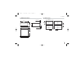
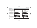
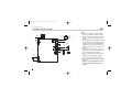
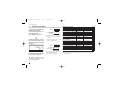
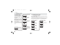
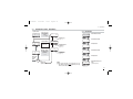
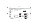
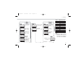
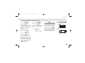
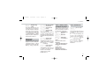
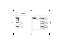
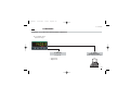
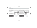
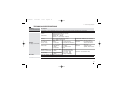
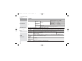
J1 EN•ed1
2-03-2005
18:14
Pagina 26
4 - Operations
4.4.3 CONFIGURATION MENU
1st part of the
configuration
code
Fields i and l allow the
selection of type and range of the
primary input (IN1 page 16).
C
# onf
Field m allows the selection of
the function mode of the display
(page 17).
2nd part of the
configuration
code
Fields oand pselect alarm
type and function (page 17).
C
# on2
SENSOR BREAK ALARM
FUNCTION
During the configuration phase
(page 17) set fileds o, p, to
value 1. When the PV overcomes
the sensor range limits, the sensor break alarm intervention is
immediate. When the alarm is no
longer present, the alarm stops
26
ABSOLUTE ALARM
During the configuration phase
(page 17) set fields o and p
to value 2 (actve high) or 3 (active low).
BAND ALARM
During the configuration phase
(page 17) set fields o and p
to value 5 (active in) or 6 (active
out).
On
Off
Active
low
hy
low range
Alarm threshold
high range
DEVIATION ALARM
During the configuration phase
(page 17) set fields o and p
to value 4 (active high) or 5 (active low).
On Active
Off high
REF
On
Off
Active
low
hy
- low range
Alarm threshold
+ high range
On Active
Off out
REF
On Active
Off high
On
Off
Active
in
hy
full scale
hy
Alarm threshold
full scale
AL1 RATE ALARM FUNCTION
During the configuration phase
(page 17) set fileds o, to value
8. When the changing rate of the
PV connected to the alarm is
higher than the specified threshold,
AL1 is actvated.
The changing rate can be set
within the limits: 0.1... 5.0 digit/s.
The alarm wil be activated in 1
second if the changin rate is
higher than 1 digit/s. At lower
rates the alarm activation time
increases to up to 6 seconds for
a limit change rate of 0.1 digit/s.