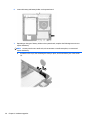
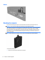
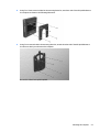
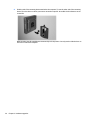
1
Hardware Reference Guide
HP 260 G1 DM Business PC
© Copyright 2014, 2015 Hewlett-Packard
Development Company, L.P.
Microsoft and Windows are U.S. registered
trademarks of the Microsoft group of
companies.
The information contained herein is subject to
change without notice. The only warranties for
HP products and services are set forth in the
express warranty statements accompanying
such products and services. Nothing herein
should be construed as constituting an
additional warranty. HP shall not be liable for
technical or editorial errors or omissions
contained herein.
Second Edition: January 2015
First Edition: October 2014
Document part number: 790976–002
Product Notice
Software terms
This guide describes features that are common
to most models. Some features may not be
available on your computer.
By installing, copying, downloading, or
otherwise using any software product
preinstalled on this computer, you agree to be
bound by the terms of the HP End User License
Agreement (EULA). If you do not accept these
license terms, your sole remedy is to return the
entire unused product (hardware and
software) within 14 days for a refund subject
to the refund policy of your place of purchase.
Not all features are available in all editions of
Windows 8. This computer may require
upgraded and/or separately purchased
hardware, drivers and/or software to take full
advantage of Windows 8 functionality. See
http://www.microsoft.com for details.
This computer may require upgraded and/or
separately purchased hardware and/or a DVD
drive to install the Windows 7 software and
take full advantage of Windows 7 functionality.
See http://windows.microsoft.com/en-us/
windows7/get-know-windows-7 for details.
For any further information or to request a full
refund of the computer, please contact your
local point of sale (the seller).
About This Book
This guide provides basic information for upgrading the HP Desktop Mini Business PC.
WARNING! Text set off in this manner indicates that failure to follow directions could result in bodily harm
or loss of life.
CAUTION: Text set off in this manner indicates that failure to follow directions could result in damage to
equipment or loss of information.
NOTE: Text set off in this manner provides important supplemental information.
iii
iv
About This Book
Table of contents
1 Product features ........................................................................................................................................... 1
Standard configuration features ........................................................................................................................... 1
Front panel components ....................................................................................................................................... 2
Rear panel components ......................................................................................................................................... 3
Serial number location .......................................................................................................................................... 4
2 Hardware upgrades ....................................................................................................................................... 5
Serviceability features ........................................................................................................................................... 5
Warnings and cautions .......................................................................................................................................... 5
Connecting the power cord .................................................................................................................................... 6
Removing the computer access panel .................................................................................................................. 7
Replacing the computer access panel ................................................................................................................... 9
Changing from desktop to tower configuration ................................................................................................. 10
Removing and replacing a hard drive .................................................................................................................. 11
Installing additional memory .............................................................................................................................. 14
SODIMMs ............................................................................................................................................ 14
DDR3L-SDRAM SODIMMs .................................................................................................................. 14
Populating SODIMM sockets ............................................................................................................. 15
Installing SODIMMs ........................................................................................................................... 16
Replacing the battery .......................................................................................................................................... 19
Installing a security lock ...................................................................................................................................... 21
Cable lock .......................................................................................................................................... 21
Padlock .............................................................................................................................................. 22
Mounting the computer ....................................................................................................................................... 22
Supported mounting options ............................................................................................................ 25
Appendix A Electrostatic discharge ................................................................................................................. 26
Preventing electrostatic damage ........................................................................................................................ 26
Grounding methods ............................................................................................................................................. 26
Appendix B Computer operating guidelines, routine care and shipping preparation ............................................ 27
Computer operating guidelines and routine care ............................................................................................... 27
Shipping preparation ........................................................................................................................................... 28
Appendix C Accessibility ................................................................................................................................. 29
Supported assistive technologies ....................................................................................................................... 29
v
Contacting support .............................................................................................................................................. 29
Index ............................................................................................................................................................. 30
vi
1
Product features
Standard configuration features
Features may vary depending on the model. For a complete listing of the hardware and software installed in
the computer, run the diagnostic utility (included on some computer models only).
NOTE: This computer model can be used in a tower orientation or a desktop orientation. The tower stand is
sold separately.
Standard configuration features
1
Front panel components
Drive configuration may vary by model.
1
Dual-State Power Button
4
Microphone Connector
2
Hard Drive Activity Light
5
Headphone Connector
3
USB 3.0 Ports
NOTE: The Power On Light is normally white when the power is on. If it is flashing red, there is a problem with the
computer and it is displaying a diagnostic code. Refer to the Maintenance and Service Guide to interpret the code.
2
Chapter 1 Product features
Rear panel components
1
AC Power Cord Connector
6
Line-Out Connector for powered audio
devices (green)
2
DisplayPort Monitor Connector
7
USB 2.0 Ports (black) with keyboard
wakeup function
3
RJ-45 (network) Jack
8
USB 3.0 Ports (blue)
4
Power Cord Retainer Clip
9
Cable lock slot
5
VGA Monitor Connector (blue)
Rear panel components
3
Serial number location
Each computer has a unique serial number and a product ID number that are located on the exterior of the
computer. Keep these numbers available for use when contacting customer service for assistance.
4
Chapter 1 Product features
2
Hardware upgrades
Serviceability features
The computer includes features that make it easy to upgrade and service.
Warnings and cautions
Before performing upgrades be sure to carefully read all of the applicable instructions, cautions, and
warnings in this guide.
WARNING!
To reduce the risk of personal injury from electrical shock, hot surfaces, or fire:
Disconnect the power cord from the wall outlet and allow the internal system components to cool before
touching.
Do not plug telecommunications or telephone connectors into the network interface controller (NIC)
receptacles.
Do not disable the power cord grounding plug. The grounding plug is an important safety feature.
Plug the power cord in a grounded (earthed) outlet that is easily accessible at all times.
To reduce the risk of serious injury, read the Safety & Comfort Guide. It describes proper workstation, setup,
posture, and health and work habits for computer users, and provides important electrical and mechanical
safety information. This guide is located on the Web at http://www.hp.com/ergo.
WARNING!
Energized and moving parts inside.
Disconnect power to the equipment before removing the enclosure.
Replace and secure the enclosure before re-energizing the equipment.
CAUTION: Static electricity can damage the electrical components of the computer or optional equipment.
Before beginning these procedures, ensure that you are discharged of static electricity by briefly touching a
grounded metal object. See Electrostatic discharge on page 26 for more information.
When the computer is plugged into an AC power source, voltage is always applied to the system board. You
must disconnect the power cord from the power source before opening the computer to prevent damage to
internal components.
Serviceability features
5
Connecting the power cord
When connecting the power supply, it is important to follow the steps below to ensure the power cord does
not pull free from the computer.
1.
Plug the female end of the power cord into the power supply brick (1).
2.
Connect the other end of the power cord to an electrical outlet (2).
3.
Connect the round end of the power supply cord to the power supply connector on the rear of the
computer (3).
4.
Route the power cord through the retainer clip to prevent the cord from becoming disconnected from
the computer (4).
5.
Bundle any excess power cord with the supplied strap (5).
CAUTION: Failure to secure the power cable with the retainer clip may result in the power cord becoming
disconnected and loss of data.
6
Chapter 2 Hardware upgrades
Removing the computer access panel
To access internal components, you must remove the access panel:
1.
Remove/disengage any security devices that prohibit opening the computer.
2.
Remove all removable media, such as a USB flash drive, from the computer.
3.
Turn off the computer properly through the operating system, then turn off any external devices.
4.
Disconnect the power cord from the power outlet and disconnect any external devices.
CAUTION: Regardless of the power-on state, voltage is always present on the system board as long as
the system is plugged into an active AC outlet. You must disconnect the power cord to avoid damage to
the internal components of the computer.
5.
If the computer is on a stand, remove the computer from the stand and lay the computer down with the
VESA holes facing up.
6.
Remove the rubber plugs from the two holes closest to the front of the computer (1).
7.
Remove the screws from the two holes closest to the front of the computer (2).
8.
Turn the computer over.
Removing the computer access panel
7
9.
8
Loosen the screw on the rear of the computer (1) then slide the panel forward and lift if off the
computer (2).
Chapter 2 Hardware upgrades
Replacing the computer access panel
1.
Place the panel on the computer then slide it back (1) and tighten the screw (2) to secure the panel in
place.
2.
Turn the computer over.
3.
Insert screws into the two holes closest to the front of the computer (1) and tighten them.
4.
Insert rubber plugs into the two holes closest to the front of the computer (2).
Replacing the computer access panel
9
Changing from desktop to tower configuration
The computer can be used in a tower orientation with an optional tower stand that can be purchased from
HP.
1.
Remove/disengage any security devices that prohibit opening the computer.
2.
Remove all removable media, such as a USB flash drive, from the computer.
3.
Turn off the computer properly through the operating system, then turn off any external devices.
4.
Disconnect the power cord from the power outlet and disconnect any external devices.
CAUTION: Regardless of the power-on state, voltage is always present on the system board as long as
the system is plugged into an active AC outlet. You must disconnect the power cord to avoid damage to
the internal components of the computer.
5.
Orient the computer so that its right side is facing up and place the computer in the optional stand.
NOTE:
stand.
6.
To stabilize the computer in a tower orientation, HP recommends the use of the optional tower
Reconnect the power cord and any external devices, then turn on the computer.
NOTE: Ensure at least 10.2 centimeters (4 inches) of space on all sides of the computer remains clear
and free of obstructions.
7.
10
Lock any security devices that were disengaged when the access panel was removed.
Chapter 2 Hardware upgrades
Removing and replacing a hard drive
NOTE: Before you remove the old hard drive, be sure to back up the data from the old hard drive so that
you can transfer the data to the new hard drive.
1.
Remove/disengage any security devices that prohibit opening the computer.
2.
Remove all removable media, such as a USB flash drive, from the computer.
3.
Turn off the computer properly through the operating system, then turn off any external devices.
4.
Disconnect the power cord from the power outlet and disconnect any external devices.
CAUTION: Regardless of the power-on state, voltage is always present on the system board as long as
the system is plugged into an active AC outlet. You must disconnect the power cord to avoid damage to
the internal components of the computer.
5.
If the computer is on a stand, remove the computer from the stand.
6.
Remove the computer access panel.
7.
Push down the release lever next to the rear of the hard drive (1). Hold the release lever down and slide
the drive back until it stops, then lift the drive up and out of the bay (2).
Removing and replacing a hard drive
11
12
8.
Unplug the combined power and data cable from the hard drive.
9.
Transfer the silver and blue isolation mounting guide screws from the old hard drive to the new hard
drive.
Chapter 2 Hardware upgrades
10. Hold the new hard drive over the bay and plug the combined power and data cable into the hard drive.
11. Align the guide screws with the slots on the chassis drive cage, press the hard drive down into the bay,
then slide it forward until it stops and locks in place.
12. Replace the access panel.
13. If the computer was on a stand, replace the stand.
14. Reconnect the power cord and turn on the computer.
15. Lock any security devices that were disengaged when the access panel was removed.
Removing and replacing a hard drive
13
Installing additional memory
The computer comes with double data rate 3 synchronous dynamic random access memory (DDR3L-SDRAM)
small outline dual inline memory modules (SODIMMs).
SODIMMs
The memory sockets on the system board can be populated with up to two industry-standard SODIMMs.
These memory sockets are populated with at least one preinstalled SODIMM. To achieve the maximum
memory support, you can populate the system board with up to 16 GB of memory.
DDR3L-SDRAM SODIMMs
For proper system operation, the SODIMMs must be:
●
industry-standard 204-pin
●
unbuffered non-ECC PC3-12800 DDR3L-1333 MHz-compliant
●
1.35 volt DDR3L-SDRAM SODIMMs
The DDR3L-SDRAM SODIMMs must also:
●
support CAS latency 11 DDR3L 1333 MHz (11-11-11 timing)
●
contain the mandatory Joint Electronic Device Engineering Council (JEDEC) specification
In addition, the computer supports:
●
512-Mbit, 1-Gbit, and 2-Gbit non-ECC memory technologies
●
single-sided and double-sided SODIMMS
●
SODIMMs constructed with x8 and x16 devices; SODIMMs constructed with x4 SDRAM are not supported
NOTE: The system will not operate properly if you install unsupported SODIMMs.
14
Chapter 2 Hardware upgrades
Populating SODIMM sockets
There are two SODIMM sockets on the system board, with one socket per channel. The sockets are labeled
DIMM1 and DIMM2. The DIMM1 socket operates in memory channel B. The DIMM2 socket operates in memory
channel A.
Item
Description
System Board Label
Socket Color
1
SODIMM1 socket, Channel B
DIMM1
Black
2
SODIMM2 socket, Channel A
DIMM2
Black
The system will automatically operate in single channel mode, dual channel mode, or flex mode, depending
on how the SODIMMs are installed.
●
The system will operate in single channel mode if the SODIMM sockets are populated in one channel
only.
●
The system will operate in a higher-performing dual channel mode if the memory capacity of the
SODIMM in Channel A is equal to the memory capacity of the SODIMM in Channel B.
●
The system will operate in flex mode if the memory capacity of the SODIMM in Channel A is not equal to
the memory capacity of the SODIMM in Channel B. In flex mode, the channel populated with the least
amount of memory describes the total amount of memory assigned to dual channel and the remainder
is assigned to single channel. If one channel will have more memory than the other, the larger amount
should be assigned to channel A.
●
In any mode, the maximum operational speed is determined by the slowest SODIMM in the system.
Installing additional memory
15
Installing SODIMMs
CAUTION: You must disconnect the power cord and wait approximately 30 seconds for the power to drain
before adding or removing memory modules. Regardless of the power-on state, voltage is always supplied to
the memory modules as long as the computer is plugged into an active AC outlet. Adding or removing
memory modules while voltage is present may cause irreparable damage to the memory modules or system
board.
The memory module sockets have gold-plated metal contacts. When upgrading the memory, it is important
to use memory modules with gold-plated metal contacts to prevent corrosion and/or oxidation resulting
from having incompatible metals in contact with each other.
Static electricity can damage the electronic components of the computer or optional cards. Before beginning
these procedures, ensure that you are discharged of static electricity by briefly touching a grounded metal
object. For more information, refer to Electrostatic discharge on page 26.
When handling a memory module, be careful not to touch any of the contacts. Doing so may damage the
module.
1.
Remove/disengage any security devices that prohibit opening the computer.
2.
Remove all removable media, such as a USB flash drive, from the computer.
3.
Turn off the computer properly through the operating system, then turn off any external devices.
4.
Disconnect the power cord from the power outlet and disconnect any external devices.
CAUTION: You must disconnect the power cord and wait approximately 30 seconds for the power to
drain before adding or removing memory modules. Regardless of the power-on state, voltage is always
supplied to the memory modules as long as the computer is plugged into an active AC outlet. Adding or
removing memory modules while voltage is present may cause irreparable damage to the memory
modules or system board.
16
5.
If the computer is on a stand, remove the computer from the stand and lay the computer down.
6.
Remove the computer access panel.
7.
Pry up the edge of the memory door closest to the side of the computer and lift the door off the
computer.
Chapter 2 Hardware upgrades
8.
To remove a SODIMM, press outward on the two latches on each side of the SODIMM (1) then pull the
SODIMM out of the socket (2).
9.
Slide the new SODIMM into the socket at approximately a 30° angle (1) then press the SODIMM down (2)
so that the latches lock it in place.
NOTE: A memory module can be installed in only one way. Match the notch on the module with the tab
on the memory socket.
Installing additional memory
17
10. Align the memory door over the SODIMMs, lower the door, and then press the door into place.
11. Replace the access panel.
12. If the computer was on a stand, replace the stand.
13. Reconnect the power cord and turn on the computer.
14. Lock any security devices that were disengaged when the computer cover or access panel was removed.
The computer automatically recognizes the additional memory when you turn on the computer.
18
Chapter 2 Hardware upgrades
Replacing the battery
The battery that comes with the computer provides power to the real-time clock. When replacing the battery,
use a battery equivalent to the battery originally installed in the computer. The computer comes with a 3volt lithium coin cell battery.
WARNING! The computer contains an internal lithium manganese dioxide battery. There is a risk of fire and
burns if the battery is not handled properly. To reduce the risk of personal injury:
Do not attempt to recharge the battery.
Do not expose to temperatures higher than 60° C (140º F).
Do not disassemble, crush, puncture, short external contacts, or dispose of in fire or water.
Replace the battery only with the HP spare designated for this product.
CAUTION: Before replacing the battery, it is important to back up the computer CMOS settings. When the
battery is removed or replaced, the CMOS settings will be cleared.
Static electricity can damage the electronic components of the computer or optional equipment. Before
beginning these procedures, ensure that you are discharged of static electricity by briefly touching a
grounded metal object.
NOTE: The lifetime of the lithium battery can be extended by plugging the computer into a live AC wall
socket. The lithium battery is only used when the computer is NOT connected to AC power.
HP encourages customers to recycle used electronic hardware, HP original print cartridges, and rechargeable
batteries. For more information about recycling programs, go to http://www.hp.com/recycle.
1.
Remove/disengage any security devices that prohibit opening the computer.
2.
Remove all removable media, such as a USB flash drive, from the computer.
3.
Turn off the computer properly through the operating system, then turn off any external devices.
4.
Disconnect the power cord from the power outlet and disconnect any external devices.
CAUTION: Regardless of the power-on state, voltage is always present on the system board as long as
the system is plugged into an active AC outlet. You must disconnect the power cord to avoid damage to
the internal components of the computer.
5.
Remove the computer access panel.
Replacing the battery
19
6.
Locate the battery and battery holder on the system board.
7.
Depending on the type of battery holder on the system board, complete the following instructions to
replace the battery.
NOTE: You may need to use a small tool, such as tweezers or needle-nose pliers, to remove and
replace the battery.
a.
20
Pull back on the clip (1) that is holding the battery in place, and lift the battery out of the holder
(2).
Chapter 2 Hardware upgrades
b.
Pull back on the clip (1) and slide the replacement battery down into the holder (2).
CAUTION: Be sure the + symbol on the battery is facing the outer edge of the computer.
NOTE:
After the battery has been replaced, use the following steps to complete this procedure.
8.
Replace the computer access panel.
9.
Plug in the computer and turn on power to the computer.
10. Reset the date and time, your passwords, and any special system setups using Computer Setup.
11. Lock any security devices that were disengaged when the computer access panel was removed.
Installing a security lock
The security locks displayed below and on the following pages can be used to secure the computer.
Cable lock
Installing a security lock
21
Padlock
Mounting the computer
HP recommends mounting the computer in the vertical (tower) orientation, with the power button up.
CAUTION: Do not mount the computer with the I/O ports oriented towards the ground.
This computer incorporates four mounting points on the right side of the computer. These mounting points
follow the VESA (Video Electronics Standards Association) standard, which provides industry-standard
mounting interfaces for Flat Displays (FDs), such as flat-panel monitors, flat displays, and flat TVs. The HP
Quick Release connects to the VESA-standard mounting points, allowing you to mount the computer in a
variety of orientations.
NOTE: When mounting to the computer, use the 15 mm screws supplied with the HP Quick Release.
To use the HP Quick Release:
1.
22
Remove four screws from the right side of the computer.
Chapter 2 Hardware upgrades
2.
Using four 15 mm screws included in the mounting device kit, attach one side of the HP Quick Release to
the computer as shown in the following illustration.
3.
Using four screws included in the mounting device kit, attach the other side of the HP Quick Release to
the device to which you will mount the computer.
Be sure the release lever points upward.
Mounting the computer
23
4.
Slide the side of the mounting device attached to the computer (1) over the other side of the mounting
device (2) on the device on which you want to mount the computer. An audible 'click' indicates a secure
connection.
When attached, the HP Quick Release automatically locks in position. You only need to slide the lever to
one side to remove the computer.
24
Chapter 2 Hardware upgrades
Supported mounting options
The following illustrations demonstrate some of the supported mounting options for the mounting bracket.
●
On the back of a flat panel monitor
●
On a wall
●
Under a desk, allowing at least 2.5 cm (1 in) clearance
Mounting the computer
25
A
Electrostatic discharge
A discharge of static electricity from a finger or other conductor may damage system boards or other staticsensitive devices. This type of damage may reduce the life expectancy of the device.
Preventing electrostatic damage
To prevent electrostatic damage, observe the following precautions:
●
Avoid hand contact by transporting and storing products in static-safe containers.
●
Keep electrostatic-sensitive parts in their containers until they arrive at static-free workstations.
●
Place parts on a grounded surface before removing them from their containers.
●
Avoid touching pins, leads, or circuitry.
●
Always be properly grounded when touching a static-sensitive component or assembly.
Grounding methods
There are several methods for grounding. Use one or more of the following methods when handling or
installing electrostatic-sensitive parts:
●
Use a wrist strap connected by a ground cord to a grounded workstation or computer chassis. Wrist
straps are flexible straps with a minimum of 1 megohm +/- 10 percent resistance in the ground cords.
To provide proper ground, wear the strap snug against the skin.
●
Use heelstraps, toestraps, or bootstraps at standing workstations. Wear the straps on both feet when
standing on conductive floors or dissipating floor mats.
●
Use conductive field service tools.
●
Use a portable field service kit with a folding static-dissipating work mat.
If you do not have any of the suggested equipment for proper grounding, contact an HP authorized dealer,
reseller, or service provider.
NOTE: For more information on static electricity, contact an HP authorized dealer, reseller, or service
provider.
26
Appendix A Electrostatic discharge
B
Computer operating guidelines, routine
care and shipping preparation
Computer operating guidelines and routine care
Follow these guidelines to properly set up and care for the computer and monitor:
●
Keep the computer away from excessive moisture, direct sunlight, and extremes of heat and cold.
●
Operate the computer on a sturdy, level surface. Leave a 10.2-cm (4-inch) clearance on all vented sides
of the computer and above the monitor to permit the required airflow.
●
Never restrict the airflow into the computer by blocking any vents or air intakes. Do not place the
keyboard, with the keyboard feet down, directly against the front of the desktop unit as this also
restricts airflow.
●
Never operate the computer with the access panel or any of the expansion card slot covers removed.
●
Do not stack computers on top of each other or place computers so near each other that they are
subject to each other’s re-circulated or preheated air.
●
If the computer is to be operated within a separate enclosure, intake and exhaust ventilation must be
provided on the enclosure, and the same operating guidelines listed above will still apply.
●
Keep liquids away from the computer and keyboard.
●
Never cover the ventilation slots on the monitor with any type of material.
●
Install or enable power management functions of the operating system or other software, including
sleep states.
●
Turn off the computer before you do either of the following:
◦
Wipe the exterior of the computer with a soft, damp cloth as needed. Using cleaning products may
discolor or damage the finish.
◦
Occasionally clean the air vents on all vented sides of the computer. Lint, dust, and other foreign
matter can block the vents and limit the airflow.
Computer operating guidelines and routine care
27
Shipping preparation
Follow these suggestions when preparing to ship the computer:
1.
Back up the hard drive files to an external storage device. Be sure that the backup media is not exposed
to electrical or magnetic impulses while stored or in transit.
NOTE:
The hard drive locks automatically when the system power is turned off.
2.
Remove and store all removable media.
3.
Turn off the computer and external devices.
4.
Disconnect the power cord from the electrical outlet, then from the computer.
5.
Disconnect the system components and external devices from their power sources, then from the
computer.
NOTE: Ensure that all boards are seated properly and secured in the board slots before shipping the
computer.
6.
28
Pack the system components and external devices in their original packing boxes or similar packaging
with sufficient packing material to protect them.
Appendix B Computer operating guidelines, routine care and shipping preparation
C
Accessibility
HP designs, produces, and markets products and services that can be used by everyone, including people
with disabilities, either on a stand-alone basis or with appropriate assistive devices.
Supported assistive technologies
HP products support a wide variety of operating system assistive technologies and can be configured to work
with additional assistive technologies. Use the Search feature on your device to locate more information
about assistive features.
NOTE: For additional information about a particular assistive technology product, contact customer
support for that product.
Contacting support
We are constantly refining the accessibility of our products and services and welcome feedback from users. If
you have an issue with a product or would like to tell us about accessibility features that have helped you,
please contact us at (888) 259-5707, Monday through Friday, 6 a.m. to 9 p.m. Mountain Time. If you are deaf
or hard-of-hearing and use TRS/VRS/WebCapTel, contact us if you require technical support or have
accessibility questions by calling (877) 656-7058, Monday through Friday, 6 a.m. to 9 p.m. Mountain Time.
Supported assistive technologies
29
Index
A
access panel
removal 7
replacement 9
accessibility 29
accessibility support
M
memory
installation 14
socket population 15
specifications 14
mounting options
on back of monitor 25
on wall 25
under desk 25
mounting the computer 22
29
B
battery replacement 19
C
computer operating guidelines
27
E
electrostatic discharge, preventing
damage 26
F
front panel components 2
G
grounding methods 26
H
hard drive
installation 11
removal 11
HP Quick Release 22
I
installation guidelines 5
installing
battery 19
computer access panel 9
hard drive 11
memory 14
SODIMMs 16
L
locks
cable lock 21
padlock 22
30
Index
P
power cord connection 6
product ID location 4
Q
quick release 22
R
rear panel components 3
removing
battery 19
computer access panel 7
hard drive 11
S
security
cable lock 21
padlock 22
serial number location 4
shipping preparation 28
SODIMMs, installing 16
specifications
memory 14
supported mounting options 25
T
tower conversion 10
V
ventilation guidelines 27