1
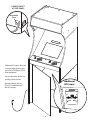
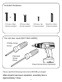
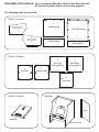
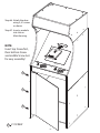
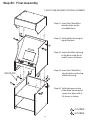
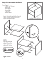
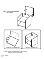
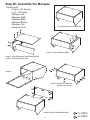
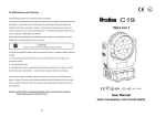
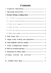
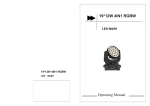
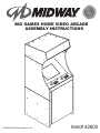
TM
BIG GAMES HOME VIDEO ARCADE
ASSEMBLY INSTRUCTIONS
© 2005 Big Electronic Games Ltd.
Item# 42600
USER MANUAL
ITEM NO. 42600
WARNING:
To reduce the risk of fire or electric shock, do not expose this appliance to rain or moisture.
CAUTION:
Use of controls or adjustments or performance of procedures other than those specified may result in hazardous
radiation exposure.
*Caution Marking was located at the rear enclosure of the apparatus
CAUTION
RISK OF ELECTRIC SHOCK
DO NOT OPEN
CAUTION-TO REDUCE THE RISK OF ELECTRIC SHOCK, DO NOT REMOVE COVER
(OR BACK). NO USER-SERVICING TO QUALIFIED SERVICE PERSONNEL.
The lightning flash with arrowhead symbol, within an equilateral triangle,
is intended to alert the user to the presence of uninsulated “dangerous
voltage” within the productʼs e nclosure that may be of sufficient magnitude
to constitute a risk of electric shock to persons.
The exclamation point within an equilateral triangle is intended to alert the
user to the presence of important operating and maintenance (servicing)
instructions in the literature accompanying the appliance.
IMPORTANT SAFETY INSTRUCTIONS
1. Read these Instructions.
2. Keep these Instructions.
3. Heed all Warnings.
4. Follow all Instructions.
5. Do not use this apparatus near water.
6. Clean only with a damp cloth.
7. Do not block any of the ventilation openings. Install in accordance
with the manufacturers instructions.
8. Do not install near any heat sources such as radiators, heat registers,
stoves, or other apparatus (including amplifiers) that produce heat.
9. Do not defeat the safety purpose of the polarized or grounding –
type plug. A polarized plug has two blades with one wider than the
other. A grounding type plug has two blades and a third grounding prong.
The wide blade or the third prong are provided for your safety. When the
provided plug does not fit into your outlet, consult an electrician for
replacement of the obsolete outlet.
10. Protect the power cord from being walked on or pinched particularly
at plugs, convenience receptacles, and the point where
they exit from the apparatus.
11. Only use attachments/accessories specified by the
manufacturer.
12. Use only with a cart, stand, tripod, bracket, or table
specified by the manufacturer, or sold with the
apparatus. When a cart is used, use caution when
moving the cart/apparatus combination to avoid injury
from tip-over.
13. Unplug this apparatus during lightning storms or when unused for long
periods of time.
14. Refer all servicing to qualified service personnel. Servicing is required
when the apparatus has been damaged in any way, such as
power-supply cord or plug is damaged, liquid has been spilled or objects
have fallen into the apparatus, the apparatus has been exposed to rain or
moisture, does not operate normally, or has been dropped.
P.2
FCC Note: USA only
This device complies with Part 15 of the FCC Rules. Operation is subject
to the following two conditions: (1) this device may not cause harmful
interference, and (2) this device must accept any interference received,
including interference that may cause undesired operation.
Warning: Changes or modifications to this unit not expressly approved
by the party responsible for compliance could void the user’s authority
to operate the equipment.
Note: This equipment has been tested and found to comply with the
limits for a class B digital device, pursuant to Part 15 of the FCC Rules.
These limits are designed to provide reasonable protection against
harmful interference in a residential installation. This equipment
generates, uses and can radiate radio frequency energy and, if not
installed and used in accordance with the instructions, may cause
harmful interference to radio communications. However, there is no
guarantee that interference will not occur in a particular installation.
If this equipment does cause harmful interference to radio or television
reception, which can be determined by turning the equipment off and
on, the user is encouraged to try to correct the interference by one or
more of the following measures:
1. Reorient or relocate the receiving antenna.
2. Increase the separation between the equipment and receiver.
3. Connect the equipment into an outlet on a circuit different from
that to which the receiver is connected.
4. Consult the dealer or an experienced radio/TV technician for help.
Compilation ©2005 Midway Amusement Games, LLC.
Robotron 2084 ©1982; Joust ©1982; Root Beer Tapper ©1983; Sinistar ©1982; Defender ©1980, Splat ©1982; Satan's Hollow ©1982; Rampage ©1986; Bubbles ©1983;
Defender II ©1981; Timber ©1984 and Wizard of Wor ©1981 Midway Amusement Games, LLC.
MIDWAY, the Midway logo, ROBOTRON 2084, JOUST, ROOT BEER TAPPER, SINISTAR, DEFENDER, SPLAT,
SATAN'S HOLLOW, RAMPAGE, BUBBLES, Timber, Wizard of Wor, Wacko and BLASTER are trademarks of Midway Amusement Games, LLC. All rights reserved.
Used by permission. Distributed under license by Big Electronic Games Limited.
©2005 Big Electronic Games Limited. All rights reserved.
DO NOT RETURN TO STORE
Weʼ re Here to Help
PLEASE CALL 1-800-749-4345 or
Visit: www.mybiggames.com
Made in China
P.11
POWER ON/OFF
AT SIDE PANEL
Resettable
Fuse
ON / OFF
Additional A/V Inputs allow you
to plug in other game systems
you have, a DVD player, VCR or
other equipment.
You can view these devices on
your Big Games monitor.
Additonal
A/V Input
Approved devices are any
UL or ETL Certified devices
with A/V outputs.
External Game
Input
Mode
P.10
Included Hardware:
or
#1 Screw x 53pcs.
(10 Extra Included)
#2 Screw x 8pcs.
(5 Extra Included)
#3 Screw x 1pc.
(1 Extra Included)
Wood Pin x 10pcs.
(4 Extra Included)
You will also need (NOT INCLUDED):
Phillips Screw
Driver
Flat-head
Screw
Driver
Power Screw Driver (Optional)
Please read the following instructions BEFORE you begin!
After all parts have been unpacked, assembly time is
Approximately 1 Hour.
P.3
Assembly Instructions:
Open and unpack Main Box, Box #1, Box #2 and Box #3.
Be sure to keep the contents of each box together.
The following parts are inlcuded:
Box #1: Contents:
(C)
(A)
Marquee Top
Marquee Top Left
(with graphics)
(E)
Marquee Bottom
(B)
Marquee Right
(with graphics)
(D)
Marquee Back
Marquee Front
(with graphics)
(F)
Box #2: Contents:
(G)
(H)
Top Shelf
Bottom Shelf
(I)
(J)
Base Left
(with graphics)
Base Right
(with graphics)
(K)
Base Back
Box #3: Contents:
Main Box
(L)
Door
e-module
Main Housing
P.4
Step #6: Attach the door
using 3, #1 screws
as shown
Step #7: Insert e-module
into slot on
Main Housing
NOTE:
Insert top Screw first,
then bottom Screw
and middle Screw last
for easy assembly!
1
1
1
1 #1 SCREW
P.9
Step #3: Final Assembly
2 ADULTS ARE REUQIRED FOR FINAL ASSEMBLY!
Step #1: Insert the 6 Wood Pins
into the holes on the
assembled base.
2
Step #2: Set the Main Housing on
top of the base.
2
2
2
Step #3: Secure the Main Housing
to the base using the #1
and #2 screws as shown.
1
WOOD PIN
Step #4: Insert the 4 Wood Pins
into the holes on the top
of Main Housing
1
1
1
2
1
2
2
Step #5: Set the Marquee on top
of the Main Housing and
secure it in place with 4,
#2 screws as shown
2
1 #1 SCREW
2 #2 SCREW
P.8
Step #1: Assemble the Base
You will need:
• 19pcs. x #1 Screws
• Base Left
• Base Right
• Base Back
• Top Shelf
• Bottom Shelf
Step #1: Attach Bottom Shelf to Base Left
Step #2: Attach Top Shelf to Base Left
Step #3: Attach Base Right
Assembled Base for Reference
1
1
1
1
1
1
1
NOTE:
You may need to
adjust the nut to
align with Screw.
1
1
1
1
1
1
1 #1 SCREW
P.5
1
Step #4: Attach Base Back to complete
base assembly
1
1
1
1
1
1
Bottom View of Assembled Base
Top View of Assembled Base
Step #5: You can put the base aside as you will not be
needing it until the final assembly.
1 #1 SCREW
P.6
Step #2: Assemble the Marquee
You will need:
• 26 pcs. x #1 Screws
• 1 pc. x #3 Screw
• Marquee Left
• Marquee Right
• Marquee Back
• Marquee Bottom
• Marquee Top
• Marquee Front
Assembled Marquee for Reference
1
1
1
1
1
1
1
1
1
1
Step #3: Attach Marquee Right
Step #1: Attach Marquee Top to Marquee Left
Step #2: Attach Marquee Front
1
1
1
Step #4:
SLIDE IN
1
1
3
1
Step #5: Attach the Marquee
Bottom in as shown
1
1
1
1
1
1
1
1
1
1
Step #6: Attach the Marquee Back
P.7
1 #1 SCREW
3 #3 SCREW