1
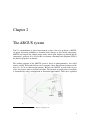
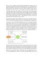
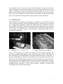
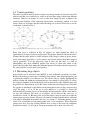
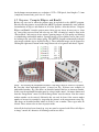
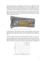
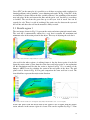
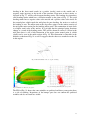
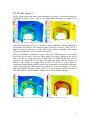
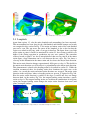
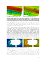
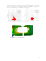
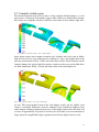
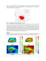
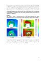
How to perform adequate optical
strain measurements
on a
sheet metal truck bumper
Sil Bijker
Report MT06.56
How to perform adequate optical strain measurements
on a
sheet metal truck bumper
Sil Bijker
Report MT06.56
Coach: Dr. Ir. R.H.J. Peerlings
Eindhoven, December, 2006
Eindhoven University of Technology
Department of Mechanical Engineering
Division of Computational and Experimental Mechanics
1
Contents
1 Introduction................................................................................................................. 3
2 The ARGUS system.................................................................................................... 4
3 Taking pictures............................................................................................................ 7
3.1
3.2
3.3
3.4
3.5
USING A STANDARD DIGITAL CAMERA ......................................................................................... 8
POSITIONING OF THE MARKERS .................................................................................................... 8
ILLUMINATION ............................................................................................................................. 9
CAMERA POSITIONS .................................................................................................................... 10
MEASURING LARGE OBJECTS...................................................................................................... 10
4 Processing the photographic data.............................................................................. 11
4.1
4.2
4.3
CAMERA PARAMETERS ............................................................................................................... 11
STEP ONE: ‘COMPUTE ELLIPSES AND BUNDLE’ .......................................................................... 12
STEP TWO: ‘COMPUTE 3D-POINTS AND GRID’ ........................................................................... 13
5 Strain measurement results for the bumper .............................................................. 14
5.1
5.2
5.3
5.4
5.5
5.6
RESULTS REGION 1 ..................................................................................................................... 16
RESULTS REGION 2 ..................................................................................................................... 18
RESULTS REGION 3 ..................................................................................................................... 19
LAMPHOLE ................................................................................................................................. 20
COMPLETE ETCHED REGION ....................................................................................................... 23
VALIDATION OF THE LS-DYNA RESULTS.................................................................................... 24
6 Conclusion and recommendations ............................................................................ 27
7 Bibliography ............................................................................................................. 29
2
Chapter 1
Introduction
The production of a sheet metal bumper consists out of several production steps that
finally lead to the bumper geometry. In this report a Daf XF bumper with a thickness of 2
mm is considered. In the production steps of the bumper, thickness reduction, residual
stresses and hardening of the material may occur. To investigate this, numerical models
have been created that simulate the production steps of the bumper. The models were
built in LS-Dyna, see [2]. To validate the models, use has been made of an optical strain
measurement technique that is implemented in the so called ARGUS system.
This report is about making such an optical strain measurement in an adequate way.
ARGUS measures the strains by computing the distances between the dots of a grid.
Before the production steps of the bumper, this grid is etched onto the undeformed sheet
metal and it deforms together with the sheet metal during the production steps. By taking
several pictures of the bumper and its deformed grid of dots, the ARGUS system can for
example compute the major and minor strain and thickness reduction of the bumper.
Several influences, such as bad illumination, low quality dots or misplaced markers, may
lead to a poor measurement. In this report these influences will be discussed and the final
results will be shown, including a comparison with the LS-Dyna results. The
measurements have been carried out in the multiscale lab at the Technical University of
Eindhoven (TU/e).
3
Chapter 2
The ARGUS system
Gom1 is a manufacturer of optical measurement systems. One of its products is ARGUS,
an optical measuring technique to determine form changes in sheet metal components.
ARGUS can compute for example major strain, minor strain, thickness reduction and the
component’s geometry. It is also possible to construct a Forming Limit Diagram (FLD) if
the material properties are known.
The working principle of the ARGUS system is based on photogrammetry, also called
remote sensing. This method allows one to compute a three-dimensional geometry on the
basis of a set of two-dimensional pictures. Because the ARGUS system works in grey
scales, the pictures must be in black and white. The location of spatial points of an object
is determined by using a triangulation of directional light bundles. This can be explained
Fig. 1 Coordinate determination of point A using photogrammetry.
1
Gom GmbH in Braunschweig, Germany. Website: www.gom.com
4
by Fig. 1, where a schematic representation of the photogrammetry principle is given. In
this figure the spatial point A in the three-dimensional space (x,y,z) is determined by two
pictures. Each picture is taken from a certain position and viewing direction in space.
This position and view direction is given by the camera coordinate system, which is
indicated by the red axes in Fig. 1. The origin of the camera coordinate system
corresponds to the camera’s lens, with the z-axis normal to the lens and light sensitive
surface. The distance between the origin of the camera coordinate system and the middle
of the light sensitive surface must be regarded as the focal length of the camera. With this
information it is possible to construct a line that goes through point A’ on the light
sensitive surface and the origin of the camera coordinate system. This is the green line
that is drawn for both pictures in Fig. 1. The coordinates of point A can now be
determined by the intersection of the two green lines.
In the previous example three parameters were necessary to determine the threedimensional coordinates of point A, namely the camera position and view direction (n
exterior orientations), the coordinates of point A’ on the light sensitive surface (Image
coordinates of n views) and the focal length of the camera (inner orientation). This is also
shown in Fig. 2 where inner orientation is replaced by camera models. Each of the four
main variables can be an input or a result of a photogrammetric method. Furthermore
additional observations play an important role: using scale bars, i.e. a known distance of
two points in space, or known fixed points, a connection to the basic measuring units is
created. In the ARGUS system first a method is used to determine the n exterior
orientations, for which the system uses the unique markers and scale bars that must be
fixated on the object to be measured. With the n exterior orientations available, it is
possible to determine the three dimensional coordinates of several points on the object.
Fig. 2 Wiora's data model of photogrammetry. Source [6]
To measure strains at the surface of the object it is necessary that a grid of dots is clearly
visible on the object. The regular grid of dots is etched onto the unprocessed steel blank.
While forming the object, the grid deforms together with the blank, and it thus contains
the necessary strain information. Note that as a result of the deformation dots can become
ellipses. In Fig. 3 on the next page a dot pattern is shown. The used dot pattern has a
diameter of 1.5 mm and has a centre to centre distance of 3 mm. Etching the grid of dots
is an electrochemical process which is also called electrolytic marking. Two types of
5
etching can be distinguished; black etching in case of steel or white etching if the
material is aluminum.
d
2d
2d
Fig. 3 Used dot pattern
Every ARGUS system comes with circular barcode markers. These markers must be
placed in the region of interest and are required for calculating the camera position with
respect to the object for each picture. At the TU/e there are two sets of markers present;
one set for steel and one for aluminum objects. Both sets are 10-bit, which means that one
set contains 100 unique markers. For large objects there is a 12 bit or a 15 bit set of
markers available with respectively 300 and 429 unique markers. In Fig. 4 a typical
marker is shown. The camera position is found by precisely determining the centre of
each marker, while the broken circle around the centre enables the software to attribute
an unambiguous ID to the marker. The set of barcode markers also contains two scale-
Fig. 4 Typical marker, magnetically placed on the object surface.
bars. A scale-bar consists of two unique markers that have a known and fixed distance.
At least one scale-bar must be placed on the object of measurement. The coordinates of
the two unique markers of the scale-bar must be determined in order to be able to scale
the measurement to real-world coordinates. If this is omitted, a correct calculation of the
strains is impossible. This is because the strain is determined by comparing the distance
between the dots in the deformed case with the original distances which must be entered
before the strain computation.
6
Chapter 3
Taking pictures
Taking the digital photographs can be regarded as the most important step in obtaining
good measurement results. Pictures of a low quality have a considerable negative
influence on the computation of the grid. If for instance certain areas of the image are
under- or overexposed, the dots have insufficient contrast and so the computation may
fail in that area, leaving gaps in the computed grid.
Fig. 5 Vosskühler CCD 1300 camera belonging to the ARGUS system
The ARGUS system is equipped with a Vosskühler CCD 4000 camera. This camera is
fixed onto a stand as shown in Fig. 5. This setup is adequate for small or medium size
objects but not for a truck bumper because it is not practical to photograph the bumper
from every direction using a fixed camera position. To overcome this difficulty, use has
been made of a ‘normal’ hand held digital camera. The following section will give more
information about using an ordinary digital camera for a measurement with ARGUS.
The purpose of this chapter is to explain how to obtain a proper set of pictures. Therefore
camera positions, illumination and positioning of the markers are discussed. The final
subject of this chapter is how to deal with relatively large measurement objects.
7
3.1 Using a standard digital camera
For photogrammetry purposes the used digital camera is not optimal because the internal
geometry of such a camera is not known accurately enough. Metric cameras must be used
if this high accuracy is desirable. Metric cameras have precisely known internal
geometries and very low lens distortions. To obtain the highest accuracy using the
standard camera no zoom function has been used, keeping the widest possible angle with
a focal length of 7.4 mm. For the photogrammetry calculations the ARGUS software
needs to be provided with the camera’s focal length, pixel resolution and its pixel size. If
these quantities are not correctly entered, this may lead to poor results or even to no
results at all. One should keep in mind in this connection that when the zoom function of
the camera is used the focal length changes. Therefore it is advisable to keep the zoom
function in the widest possible angle during the measurement.
The dots or ellipses in a picture must contain a certain number of pixels to be identified
by the ARGUS software. If the ellipses have a diameter of ten or more pixels, the ellipse
finder may not work because of the graylevel distribution inside the ellipses. They may
also not be smaller than five pixels because otherwise the graylevels of the object and its
surroundings introduce false ellipses. The mentioned pixel values can change if the
default settings are adjusted.
3.2 Positioning of the markers
As mentioned in chapter 2, markers are necessary for the ARGUS software to calculate
the camera position in each image. The markers have been printed on magnetic foil so
they adhere to objects made of steel. They are to be distributed around the area to be
measured in such a way that at least five markers are visible from each perspective and
that these markers are not in a straight line. It is safer to have more than five markers
visible. For a better computation of the camera positions it is wise to place some
additional markers at a little distance from the measurement area, preferable in a way that
they are not lying in one plane with the other markers. Fig. 6 shows an example of
marker positioning.
Scale-bar
Fig. 6 Example of how the markers could be placed. Note that the markers do not
have do be directly on the object’s surface.
8
As the picture shows, it is not necessary to place the markers directly on the object’s
surface. During the measurement, the markers may not be moved with respect to each
other and with respect to the etched pattern on the sheet metal. This is no issue if all
markers are fixed directly onto the object surface. However if this is not the case, like in
Fig. 6, care must be taken not to move the object or the markers. If movement has taken
place, the system may be divergent and no camera positions can be determined.
3.3 Illumination
The illumination of the object is an important issue which has a crucial influence on the
success of the measurement. The most desirable situation is that the area to be measured
has a homogeneous distribution of light. The light being used to illuminate the object
must be diffuse to limit the reflection of the steel surface. If reflections occur, no dots are
visible in this area, resulting in a loss of information. Even with diffuse light reflections
are inevitable, especially in corners or curved surfaces. Unfortunately these areas are
often the most interesting.
Fig. 7a Illumination setup. Creating diffuse light by
using paper.
Fig. 7b Additional markers place on a non shiny dark
surface to reduce the amount of backlight.
In Fig. 7a an example is given of how the illumination of the bumper experiments has
been set up and how diffuse light has been created using paper covers of the lamps. To
have full control over the illumination, measurements have been done in a dark room, so
that no external light can interfere. It is preferable not to use the flash of the camera, but
because of a lack of diffuse light the flash has been used with the present measurements.
Fig. 7b shows that some additional markers have been placed on a dark surface to reduce
the backlight. If a white background were used for the same measurement, the resulting
backlight would necessitate a small camera aperture, resulting in underexposed
measurement areas and poor measurements.
9
3.4 Camera positions
The camera positions must be chosen so that every image contains at least five bar-coded
markers and that every etched dot is visible in at least three images taken from different
directions. However, in practice it is wise to take more images in order to improve the
precision and reliability of the calculated object-points. An effective method is to first
create a basic set of pictures and then refine the image set as needed. The basic set can be
constructed as shown in Fig. 8.
Fig. 8 Camera positions for taking pictures of the object: a top view, b side view. Source [7]
From each level as indicated in Fig. 8b pictures are taken around the object at
approximately 45 degrees between each picture. The pictures should be taken from such a
distance that the entire object is visible and most of the image is taken up by the object.
Areas with simple geometries, e.g. flat surfaces, need fewer pictures than more complex
curved geometries. If in the processing stage it turns out that there is a lack of
photographic data, then additional pictures can always be taken and added to the
processing. Note that while taking the additional pictures all markers must be in precisely
the same positions as in the basic set of pictures.
3.5 Measuring large objects
Large objects can be measured with ARGUS if some additional precautions are taken.
Because the marker per area ratio is smaller for large objects, more attention must be paid
to placing the markers in an efficient way. This can be done by equally distributing the
markers around and within the measurement area. An example is given in Fig. 7b, where
the complete lamphole of the finished part has been measured at once. Markers must only
be placed in the measurement area if the strains in that area are homogeneous. Only then
the gap that is introduced by the marker can be interpolated safely in the post-processing
stage. By using a 12 or 15 bit set of code markers it is possible to extend the
measurement area further. In case of the bumper measurements the 10-bit coded-marker
set was still sufficient. The basic set of pictures can be taken in the same way as
described in section 3.4. Because of the size of the object it may be necessary to take the
pictures from a greater distance. However, the camera resolution should then be sufficient
to be able to distinguish the markers and dots, see section 3.1. Additional pictures can be
taken if for a particular area the photographic data is not satisfactory. These additional
pictures may be a close-ups of that particular area as long as they meet the conditions
described in section 3.4. A result of a large measurement area is shown in section 5.5.
10
Chapter 4
Processing the photographic data
In the processing stage two steps can be distinguished. First the computation of the
ellipses and bundles is done and then the computation of the 3D-points and grid. The
former step is the most important, because it converts the photographic data to
geometrical data, which is crucial for the outcome of the further computations. In this
step the software tries to recognize the ellipses and bar coded markers and from them
computes the three-dimensional camera positions. In the latter step the recognized
ellipses are converted to 3D-points which subsequently are used to generate the grid. The
grid consists of elements that are created by using the 3D-points as nodes for each
element. For both these steps some useful tips will be given to improve the computational
results. This chapter can be regarded as an addition to the abridged user manual
(v 5.4) [4].
4.1 Camera parameters
The ARGUS program uses many parameters and settings. It is recommended to use the
default setting for most of these parameters, but there are a few parameters to be known.
Because use has been made of an external camera, there are three important parameters
that have an influence on the computational results, namely camera resolution, focal
length and the size of one single pixel of the light sensitive sensor of the camera. The
most important parameter is the resolution of the camera. This must exactly correspond
with the true camera setting to be able to add pictures to the ARGUS program. Also be
sure that the focal length is set correctly. If the focal length does not exactly correspond
with the true camera setting, this will lead to poor 3D-points and grid. In extreme cases
the ‘computation of ellipses and bundle’ step may fail with the following error:
[MTRITOP-CMP002 system is divergent]. This is why it is strongly recommended not to
use the zoom function of the camera during the measurement. For the pixel-size
parameter the same consequences hold as for the focal length. The camera settings used
11
for the bumper measurements are: resolution = 2272 x 1704 pixels, focal length = 7.4 mm
(completely zoomed out), pixel size = 3.12 µm.
4.2 Step one: ‘Compute Ellipses and Bundle’
Before step one can be taken the pictures must be uploaded to the ARGUS program.
Directly after the pictures are uploaded the ARGUS program automatically starts with the
determination of ellipses and markers in all of the pictures. After that choose ‘Compute
Ellipses and Bundle’ from the project menu. After step one it may be necessary to ‘clean
up’ some of the processed data and redo step one. This ‘cleaning up’ must be done in the
‘Project Mode’ and consists of two actions: ignoring images of poor quality and deleting
or renumbering unidentified markers. Ignoring images of poor quality can be done easily
by looking in the root of the image-group. The ARGUS program automatically indicates
poor images with the sign as depicted in Fig. 9. These indicated images can be ignored by
clicking the right mouse button on the image that needs to be ignored and choose ‘Ignore
Fig. 9 Image root. Image 24 must be ignored.
Fig. 10a Incorrect numbering of marker.
Fig. 10b Marker does not exist and must be deleted.
image’. For deleting the unidentified markers each image must be looked at separately.
Be sure that ‘show unidentified points’ is turned on. Fig. 10 shows two examples of
unidentified markers. Fig. 10a shows an identified marker that has an incorrect number.
In this case the unidentified marker must be selected with control - left mouse button and
from the “Image Point” menu “Set ID for Image Point” must be chosen. Now the correct
marker number can be entered. Obviously this can only be done if the correct marker
number is known, for example by inspecting the pictures or the measurement setup. Fig.
10b shows an identified marker which in reality is not a marker. These types must be
deleted. These actions also are done in project mode.
After all the data has been cleaned up, step one must be repeated with “Reset all ellipses
in image” turned off; otherwise all cleaning work has no effect.
12
4.3 Step two: ‘Compute 3D-Points and Grid’
In step two one image-point, which represents an ellipse, must be selected in a picture
that is preferably taken from above the object. From this particular image-point the
computation will start and propagation of the grid will thus start from that point. In
practice step two usually has to be done several times to get a complete grid. The cause of
this is that the propagation of the grid often can not proceed because there are not enough
image-points available to successfully determine the 3D-point coordinates. If this is the
case the 3D-point is not accepted and therefore the grid cannot be expanded further,
creating a boundary of the grid. To expand the grid further, step two can be repeated at
another image-point which does not belong to a grid. At the end, when no further
expansion of the grid is possible, the individual grids can be combined to one single grid.
If there are still areas with no 3D-points and grid, it is possible to manually add 3D-points
by selecting one individual image-point in two different pictures. This can be done by
selecting an image-point and pressing control - left mouse button. In the right bottom
corner of the screen a second image appears. Select another image near to the first image
in the Explorer and press control - left mouse button in the right image on the same
image-point as in the left image. To help find the corresponding image-point in the right
image ARGUS shows a so called epipolar line. The searched image-point must lie
somewhere on that line.
The last tip is to be careful with accepting a grid. Fig. 11 shows that the elements of a
grid sometimes do not have the correct shape, resulting in very high and unrealistic
computed strains at that particular element.
Fig. 11a Correct grid.
Fig. 11b Incorrect grid.
13
Chapter 5
Strain measurement results for the
bumper
The procedure as discussed in the previous chapters has been applied to a Daf truck
bumper. To obtain information on the evolution of strain during the different production
steps not only the finished bumper has been measured but also a semi-finished bumper,
which was obtained after the first step of the production process. In this first production
step the main shape of the bumper is made by pressing the blank into a die. Also a slitting
operation is used at the position of the lamphole. The second step consists of some
trimming operations.
Fig. 12 The etched areas of the finished and semi-finished bumper. Source [7]
As discussed in chapter two a regular grid of dots must be etched onto the unprocessed
steel blank. The etching process has been carried out by Kommer [7], who also
14
preformed measurements on the bumper but encountered some difficulties. The dot
pattern that has been etched on both bumpers does not cover the complete surface of the
bumper and therefore results have been obtained for a few regions. Furthermore, because
of symmetry, only half of the bumper is considered. Fig. 12, shows the etched parts on
the semi-finished (top) and finished bumper (bottom). For the validation of the LS-Dyna
models certain regions were identified, which will be compared with the ARGUS results.
These regions are depicted in Fig. 13. The three regions are discussed in the first three
sections. The final two sections contain the results of larger measurement areas and the
validation of the LS-Dyna results.
Fig. 13 Three regions for the comparison of the LS-Dyna results. Source [2]
All strains presented in the following are natural, or true logarithmic, strains. The major
and minor strains are shown on the object’s surface. The major strain is the maximum inplane principal true strain and the minor strain is the minimum in-plane principal true
strain.
The obtained thickness reduction and a Forming Limit Diagram (FLD) are also shown as
results. In an FLD the major and minor strain combination, of all nodes of the 3D-grid are
represented graphically in a two-dimensional plot. In this plot the combination of major
and minor strain for each ellipse is visualized by a dot, where the x-axis represents the
minor strain and the y-axis represents the major strain. By introducing a Forming Limit
Fig. 14 Forming Limit Curve of the used bumper material.
15
Curve (FLC) in the same plot, it is possible to see if there are regions with a tendency for
forming problems such as wrinkles, severe thinning and cracks. In Fig. 14 the FLC of the
used material is shown. Below the blue ‘wrinkle tendency’ line wrinkling of the material
may take place. In the area between the blue and the green ‘safe’ line there is a tendency
to wrinkle. The area from the green line up to the cyan ‘risk of crack’ line can be
regarded as safe. There is a risk of cracking if the strain state lies between the cyan and
the red line and above the red line the material is likely to crack.
5.1 Results region 1
The two images shown in Fig. 15 represent the major and minor principal natural strain.
The scale bar is automatically adjusted in a way that it contains the maximum and
minimum value of the strain present in the object. This way of adjusting the scale bar is
A
Major strain
Minor strain
Fig. 15 Major (left) and minor (right) strain for region 1 at surface level.
also used for the other regions. A striking feature is the fact that at point A in the left
figure the major strain is lower than the value above and below point A. An explanation
for this fluctuation could be that the strain as depicted in Fig. 15 is at surface of the
bumper. ARGUS can also calculate the strain in the mid plane of the sheet. The mid
plane result is shown in Fig. 16. For good comparison the same scale bar is used. The
short black lines represent the major strain direction.
Section 0
Fig. 16 Major strain and direction in mid plane (left), Major strain multi-section, section 0 (right).
In this mid plane result the major strain in the concave area is higher than the surface
strain, whereas in the convex region it is lower. This can be explained by Fig. 17. Pure
16
bending in the sheet metal results in a positive (tensile) strain at the outside and a
negative strain (pressure) at the inside of the curvature. From now on these strains, as
depicted in Fig. 17, will be called tangent bending strains. The bending also introduces
axial bending strains which have a direction normal to the plane of Fig. 17. The axial
bending strains have a negative value at the outside and a positive value at the inside. In
the neutral plane, which equals the mid plane for pure bending, the strain as a result of
the bending is zero. The major strain at the edge above point A at the surface consists of
the mid plane major strain plus the bending major strain. This summation of strain leads
to a higher strain value at the surface. It is possible that the principal strain directions
change as a result of the bending strains. This will be shown in section 5.4. Even in the
mid plane there is still a little fluctuation of the major strain around point A, which
clearly can be seen in the multi-section of Fig. 16. This fluctuation is noticeable in the
thickness reduction of Fig. 18 as well. It suggests that the sheet was stretched over the die
in this region.
+ε
-ε
Fig. 17 Strain distribution in case of pure bending.
Fig. 18 Thickness reduction of region 1.
Fig. 19 Forming Limit Diagram of region 1.
The FLD of Fig. 19 shows that some wrinkles are predicted and that at some points there
is a risk of cracking. Inspections of the bumper part does not confirm the predicted
wrinkles and also no cracks are visible.
17
5.2 Results region 2
In Fig. 20 the major and minor strain distribution of region 2 are shown. Notice the
irregularity at point A. This is due to poor interpolation. Point B is an example of a
A
A
B
B
C
Major strain
Minor strain
Fig. 20 Major (left) and minor (right) strain for region 2 at surface level.
successful interpolation. In Fig. 21 the major strain distribution is shown without any
interpolation and with the same indicated points A and B. At point C in Fig. 20, 21 a
highly concentrated strain area is visible. This strain would be even higher if the slitting
operation in production step one would be omitted [2].
In Fig. 22 the thickness reduction of region 2 can be seen. Thinning mostly occurs on the
bend edges and at point C, where the major strain is the highest. Observing the grid of
ellipses at point C, a high strain area is clearly visible. A verification has been done by
measuring the dimensions of an ellipse and comparing them with the original dot
diameter. This resulted in a major strain at point C of ln(2.5/1.5) = 0.51, which is
significantly higher than the ARGUS result. Also verification for the thickness reduction
at point C has been done. This resulted in a reduction of 27 percent, which is 2.7 percent
higher than ARGUS predicts. Finally in Fig. 23 on the next page, the FLD of region 2
shows that there is a risk of wrinkles, which are not visible on the real bumper.
A
B
C
Fig. 21 Major strain of region 2, without interpolation.
C
Fig. 22 Thickness reduction of region 2.
18
Fig. 23 Forming limit diagram of region 2.
5.3 Results region 3
In Fig. 24, the major and minor strain of region 3 are shown. The big gap is due to the
fact that the ellipses in that particular area were of low quality. The gap has not been
interpolated because it is too big to interpolate it in a meaningful way. In ARGUS it is
possible to use filters to smoothen the strain results. To give an example why such
filtering is generally undesirable, the major strain result of Fig. 24 has been filtered and
plotted in Fig. 25. Just like the previous major and minor strain results the scale bar is
automatically adjusted in a way that it contains the maximum and minimum value of the
Fig. 24 Major (left) and minor (right) strain for region 2 at surface level.
strain present in the object. The filter has lowered the maximum and raised the minimum
value of the strains, and also has an effect on the intermediate strain values. For the
maximum strain area the filtered value is 18 percent lower. Therefore, one must be
careful using these filters because they manipulate the results. Fig. 26 shows the
thickness reduction of region 3.
19
Fig. 25 Filtered result of the major strain of region 3.
Fig. 26 Thickness reduction of region 3.
5.4 Lamphole
Apart from regions 1-3, also the entire lamphole and surroundings has been measured.
This measurement has been done for the semi-finished and finished bumper and results
are compared in this section. In Fig. 27 the major and minor strain of the semi-finished
part can be seen. The gap across the center of the lamphole is due to the fact that the
region was etched in two parts, with a 2 cm gap in between. The figure shows very high
major strains at points A and B. As mentioned in section 5.2, these strains would be even
higher if the slitting operation in production step one were omitted. The somewhat
scattered results at point C are due to interpolation of that area. In point D of the minor
strain figure a large fluctuation can be seen between the two edges. Fig. 28a shows a
close up of this fluctuation in the minor strain and also shows the major strain direction.
This major strain direction changes approximately 90 degrees at edge A. This holds for
the minor strain direction as well, because it is perpendicular to the major strain direction.
This phenomenon is related to the bending strains as described in section 5.1. Unlike the
situation encountered there, the bending strains here dominate the strain state at the
surface. As a result, the major and minor strain directions are swapped. The major strain
direction in the mid plane, where no bending strains are present, is depicted in Fig. 28b.
Here the major strain direction is parallel to the edges A and B and does not change
between them. At the surface, Fig. 28a, the tangent bending strains introduce a tensile
strain at edge A. The tangent bending strains are such that the combination of mid plane
strain plus tangent bending strain changes the major strain direction from axial (mid
plane) to tangent (surface).
C
A B
D
Fig. 27 Major (left) and minor (right) strain for semi-finished lamphole at surface level.
20
Edge A
Edge B
Fig. 28a Minor strain and major strain direction
at the surface.Close up of point D.
Edge A
Edge B
Fig. 28b Minor strain and major strain direction
at mid plane. Close up of point D.
The minor strain value at edge A at the surface is higher than at the mid surface because
of the switch in principal strain directions. The major strain at the mid plane plus the
negative axial bending strain at the surface has become the minor strain at edge A at the
surface. For edge B the major and minor strain directions remain the same because the
axial bending strain at this edge is positive (tensile) and thus will increase the major
strain. Furthermore the negative tangent bending strain at edge B decreases the minor
strain, which is also visible by the blue color.
In Fig. 29, the same images are shown for the finished lamphole. The gaps at both sides
of the lamphole are holes for the fixation of the lamps etc. The same scale bars are used
as with the semi-finished lamphole of Fig. 27, so a good comparison between both
production steps can be made. The high major strains at points A and B of Fig. 27 are not
present on the finished lamphole because they have been cut away by the slitting
operation of the second production step. Otherwise the major strain distribution of the
finished part corresponds well with that of the semi-finished lamphole. This also holds
for the minor strain. This indicates that the final forming steps introduce relatively little
additional deformation and the overall shape of the bumper is largely formed in the first
step. The blue areas near point D in the minor strain distribution shown in Fig. 27 are not
visible in the finished part because of that particular area no results have been obtained.
Fig. 29 Major (left) and minor (right) strain for finished lamphole at surface level.
The FLDs of the finished and semi-finished parts near the lamphole can be seen in Fig.
30. The higher strains at point A and B of the semi-finished part are also noticeable in the
corresponding FLD. These points, as well as those in the wrinkling regime, are largely
removed by the trimming. In the semi-finished part wrinkles are visible near the cutting
edges. For the finished part no wrinkles are visible. The last figure of this section, Fig.
31, shows the thickness reduction of the finished part. This diagram shows a limited
21
amount of thinning, except in the bent region around the lamphole and at the edge of the
lamphole, where a significant thinning (approx 25%) has occurred. This corresponds well
with the fact that these regions are biaxially stretched (Fig. 29).
Fig. 30 FLDs for semi-finished lamphole (left) and finished lamphole (right).
Fig. 31 Thickness reduction of the finished lamphole.
22
5.5 Complete etched region
The final measurement that has been done is of the complete finished bumper, or to be
more precise, of that part of the bumper (approx 40%) which was etched before forming.
The results are acceptable, but they could have been better if more diffuse light and a
Fig. 32 Major strain at the surface of the complet bumper.
better digital camera with a higher resolution were available. Due to the lack of diffuse
light the curved areas were underexposed, resulting in a lower grid quality than in the
previous measurements. In Fig. 32 the result of the major strain is shown. Because not the
complete bumper has got the etched dot pattern, certain areas have no grid and thus have
no strain information. In Fig. 33 below the minor strain of the total bumper can
Fig. 33 Minor strain at surface level of the total bumper.
be seen. The correspondence between the total bumper results and the smaller sized
results is reasonable. Differences must be attributed to the insufficient lighting of the
entire bumper resulting in underexposed areas. In the highly strained areas this may lead
to errors of approximately 25 percent. It is believed to be feasible to do a measurement of
larger objects if enough diffuse light is guaranteed and a better digital camera is used.
23
Fig. 34 shows the FLD of the complete bumper. It suggests that wrinkles are definitely
present and that there is a risk of cracking for a few points. However, no wrinkles or
cracks are visible on the real bumper.
Fig. 34 FLD of complete finished bumper.
5.6 Validation of the LS-Dyna results
Now the strain results of the different regions are available it is possible to compare the
forming simulation results (using LS-Dyna) with the ARGUS measurements. The used
regions for this validation are depicted in Fig. 13 on page 15 and belong to the semifinished bumper. The ARGUS and LS-Dyna results are at the mid plane. In some small
areas of the ARGUS results interpolations have been carried out. It will be mentioned if
these interpolations give an unrealistic or peculiar effect. More information about the LSDyna models and forming process can be found in [2].
Region 1
In Fig. 35 below, the major and minor strains of region 1 are compared. The fluctuation
at point A, which was discussed in section 5.1, is not visible in the LS-Dyna results.
A
Fig. 35 Comparison between LS-Dyna and ARGUS for region 1. Left: major strain; right: minor strain.
24
In this and other regions, the LS-Dyna results are much smoother than those of ARGUS.
In ARGUS it is possible to create such smooth results by using a filter. But, as mentioned
in section 5.3, it will lower the maximum strain values in a more or less arbitrary way.
The small fluctuations of the ARGUS results are only visible in the low strain regions.
The fluctuations have A wavelength which approximately equals the grid spacing and are
probably measurement errors with an absolute error of approximately 0.02 εln. Apart from
the fluctuations in the ARGUS result, the general agreement between measurement and
simulation is remarkable.
Region 2
The results of region 2 are shown in Fig. 36. The arrows indicate areas where
interpolation has been used and gave an irregular strain pattern. Besides these points the
B
A
Fig. 36 Comparison between LS-Dyna and ARGUS for region 2. Left: major strain; right: minor strain.
major strain resemblance is good. Even the shade of light blue at point A of the LS-Dyna
result is confirmed by the ARGUS image. For the minor strain the correspondence is
slightly poorer. Especially above and below the lamphole, indicated by B, where the LSDyna result seems to be higher than measured by ARGUS.
25
Region 3
The images of the last region can be seen in Fig. 37. The big gap in the ARGUS image of
both major and minor strain is due to poor ellipse quality in that area. Interpolating such a
gap is unacceptable because it will generate a nonphysical strain field. The few spots near
point A are another example of an interpolation error. The remainder of the major and
minor strain correspondence between ARGUS and LS-Dyna is again satisfactory.
A
A
Fig. 37 Comparison between LS-Dyna and ARGUS for region 3. Left: major strain; right: minor strain.
26
Chapter 6
Conclusion and recommendations
The main requirements for an accurate strain measurement using ARGUS is a set of
proper digital pictures. This can be established by correct illumination, marker
positioning and proper camera use:
•
The illumination of a measurement object must be diffuse to reduce reflections
and must result in a homogeneous light distribution, covering the complete object.
Preferably the measurement should be done in a dark room so that no external
light can influence the controlled illumination.
•
The markers have to be distributed around the area to be measured in such a way
that at least five markers are visible from each perspective. These markers may
not form a straight line and preferable should not all lie in the same plane.
During the measurement, the markers may not be moved with respect to each
other and to the etched pattern on the sheet metal
•
The following camera settings are important for the ARGUS system and must be
entered correctly: pixel size, pixel resolution and focal length of the camera. Extra
care must be taken with the latter because it changes if the zoom function is used.
Therefore it is advisable not to zoom during a measurement. One should realize
that these settings are of great importance because they are used in the
photogrammetric computations.
•
Measuring large objects is feasible if a proper illumination setup is used. The
currently available illumination is sufficient for small and medium sized objects
and individual measurement regions of the bumper. Because of a lack of diffuse
light this setup is insufficient for large measurement objects such as the complete
bumper.
27
With large objects it may be necessary to take photographs from a greater
distance, resulting in a change of the number of pixels that an ellipse contains.
The diameter of an ellipse must be between approximately five and ten pixels.
The camera resolution should then be sufficient to be able to have the ellipse
diameter between its limits or larger dots should be used.
The results in this study demonstrate two more important aspects of the measurement:
•
One must be careful using filters that smoothen the results because they lower the
maximum and raise the minimum value of the strains, possibly creating a
nonphysical strain field. ARGUS is equipped with three different types of filters
with accompanying settings. These filters and settings have not been investigated
enough in this study but may be of interest in another study.
•
Also care must be taken in using the interpolation tool to fill up gaps in the grid.
Only make use of it if the gap is small and the strain has no rapid changes in that
particular region.
The results of the individual regions are quite satisfactory, but they could have been
better for the complete bumper if the illumination were sufficient. Also the LS-Dyna
results correspond well with the ARGUS results.
In this study measurements have been done of the complete etched region of the bumper
and of the individual regions. In the latter the measurement areas are still relatively large
and the used grid pattern was always the same. Some external measurements have been
preformed for a different project where a fine grid was used and the measurement area
was small. These measurements gave some problems which could not directly be solved
by the knowledge obtained in this study. Therefore it may be useful to investigate some
small scale measurements with different grid sizes.
28
Bibliography
1. A. Aydemir, Forming to crash – Process simulation of DAF bumper 10680,
Netherlands institute of metal research, April 2006, Nieuwegein
2. T. van Hoek, The history influence of forming on the predicted crash performance
of a truck bumper, Technical University Eindhoven, August 2006, Eindhoven
[MT06.36]
3. Gom optical measuring techniques, ARGUS – Sheet metal forming measuring
system – Introduction (v 4.7), Gom GmbH, 2001, Braunschweig
4. Gom optical measuring techniques, ARGUS – abridged user manual (v 5.4), Gom
GmbH, 2005, Braunschweig
5. Website of University of Vienna ‘Introduction to Photogrammetry’ url:
http://www.univie.ac.at/Luftbildarchiv/wgv/intro.htm
6. Wikipedia,
Free
Encyclopedia
http://en.wikipedia.org/wiki/Photogrammetry
Photogrammetry
url:
7. N. Kommer, Optical strain measurement on a DAF truck bumper, Technical
University Eindhoven, December 2006, Eindhoven [MT06.53]
29