1
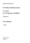
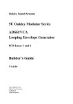
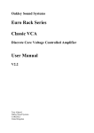
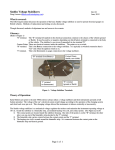
Oakley Sound Systems
Rack Power Supply Unit
(RPSU)
PCB Issue 1
Builder's Guide
V1.0.2
Tony Allgood
Oakley Sound Systems
CARLISLE
United Kingdom
1
Introduction
This is the Project Builder's Guide for issue 1 of the RPSU circuit board from Oakley Sound.
This document contains a full parts list for the components needed to populate the board and
some basic testing methods.
You will also need the RPSU User Manual which gives details on how to use the module as
well as example wiring diagrams. This can be found on the RPSU webpage.
For general information regarding where to get parts and suggested part numbers please see
our useful Parts Guide at http://www.oakleysound.com/parts.pdf.
For general information on how to build our modules, including circuit board population,
mounting front panel components and making up board interconnects please see our
Construction Guide at http://www.oakleysound.com/construct.pdf.
A completed RPSU board built in full wave rectification mode and fitted with Molex KK headers
2
Parts List
The components are grouped into values, the order of the component names is of no particular
consequence.
A quick note on European part descriptions:
For resistors: R is shorthand for ohm. K is shorthand for kilo-ohm. M is shorthand for megaohm
For capacitors: 1uF = 1,000nF = 1,000,000pF. Sometimes the F is not included on the circuit
diagram to indicate a capacitor's value, ie. 100n = 100nF.
To prevent loss of the small ‘.’as the decimal point, a convention of inserting the unit in its
place is used. eg. 4R7 is a 4.7 ohm, 4K7 is a 4700 ohm resistor, 4n7 is a 4.7 nF capacitor.
Resistors
All resistors are 0.25W 1% metal film or better.
47R
240R
2K2
10K
R5*
R3, R4
R1, R2
R6
* If the RPSU is to be used within a project featuring an internal mains transformer then R5
should be a wire link and not a resistor. A resistor lead clipping is normally long enough for
this purpose.
If +/-12V operation is required then you should make both R1 and R2 each a 1K5 resistor.
Capacitors
100nF, 63V multilayer axial ceramic
10uF, 35V or 50V electrolytic
22uF, 35V or 50V electrolytic
1000uF, 35V or 50V electrolytic
C1, C4, C5, C6
C2, C3, C7, C8
C13
C9, C10, C11, C12
C9 to C11 are radial types and have standard wire ended leads. Lead spacing is either 5mm or
7.5mm. Do not get 'push-fit' types as their pins are too large to fit into the PCB. Ensure they
have a ripple rating of at least 750mA.
3
Discrete Semiconductors
1N4002 or 1N4004
D1, D2, D3, D4, D5, D6, D11
Because of space limitations D5 and D6 have to be fitted to the board after fitting the PSU1
and PSU2 headers.
1N5401
D7, D8, D9, D10
D9 and D10 do not need to be fitted if you are using a single phase wall wart or line lump.
However, for full wave rectification D9 and D10 are required. So if you are using a split
output line lump or an internal transformer with twin secondaries D9 and D10 have to be
fitted.
LED
This is an optional part and can either be fitted direct to the board for fault finding use or to
the front panel as a 'power on' indicator. For the latter I would suggest that you fit 2-way 0.1”
KK or MTA header on the board in place of the LED.
5mm green LED
AC
Integrated Circuits
LM317T 1A variable regulator
LM337T 1A variable regulator
U1
U2
Ensure that both devices are TO-220 types and not any surface mounting or TO-3 packages. I
much prefer the devices that are made by National Semiconductor. They are available from
other manufacturers but National's devices have a thicker and more rigid heatsink tab.
Do not fit solder these into the board just yet. They are only to be soldered once the board is
fitted to the panel. See the section on mounting the RPSU board later in this document.
4
Miscellaneous
1K multiturn cermet trimmer
0.156” Molex KK 4-way header
800mA antisurge 20mm fuse
20mm fuseholder PC mount
4-way screw terminal 5mm
POS, NEG
PSU1, PSU2
F1*, F2
F1*, F2
POWER, SWITCH
2 off TO-220 insulator
2 off TO-220 insulating bush
Heatsink paste
For mounting of U1 and U2 to panel
For mounting of U1 and U2 to panel
For mounting of U1 and U2 to panel if using mica plates
Suitable power switch
Suitable power socket
Various screws, washers and other mounting hardware.
* If you are using the recommended wall-wart, or single phase line lump, then fuseholder F1
and it associating fuse does not need to be fitted. F1 and F2 are only required if you are using
a split output line lump or internal mains transformer for full wave rectification.
5
Attaching the Power Devices
In this build the two regulators are insulated from the panel with grey insulating pads. Note the thinner
metal tab on the upper device compared to the thicker National LM337T.
The RPSU PCB needs to be fitted to your case metalwork. Use the PCB as a template for the
four holes needed for the mounting pillars. The board should be spaced high enough off the
panel so as to not short out any of the components' leads should the board be flexed
downward. However, they should also not be too long so that the leads from the two
regulators can't reach through the board to be soldered. I find an 8mm spacer works very well.
Now you need to prepare the leads of the two power devices. The three legs need to be bent
upwards so that the PCB can be fitted over them. Note that the top surface of the device is
marked with the name of the component and it is the flat side on the bottom of the device that
will be in contact with the panel. You should be able to see that the leads have a thicker
section close to the body of the device. Make a 90 degree bend upwards at the point where
the lead thickness changes. Do this for all three legs of the device.
Remove the board from the panel and fit the power devices to the board by poking their legs
up through the bottom of the board. Do not solder them but fit the board back into place. Use
the hole in each regulator to mark out where you need to drill the mounting hole for the two
devices. Now remove the board and regulators. Carefully drill a 3.5mm hole in the panel for
6
each of the regulators. Clear off any swarf and, twisting with your hand only, use an 8mm drill
bit to lightly deburr the edges of the holes. There should be no bumps around the holes.
The regulators are both TO-220 devices. They both need to be fitted to the panel mechanically
and thermally but not electrically. That is the metal tab on each device that will be mounted to
the panel should not make electrical contact with the metal panel. To achieve both thermal
transfer and electrical insulation we use an insulator. These can be made of a 'soft' flexible
material in the form of an insulating pad or a rigid thin glass like plate made from mica. If
using the mica you will also need to use heat transfer paste. Since the paste is somewhat messy
I recommend you use the insulating pads. Both types are normally available in 'mounting kits'.
Also in the kit is a mounting bush. This top hat shaped piece of stiff plastic prevents the
mounting screw from touching the regulator's metal tab.
Now place the mounting bush into the hole of the transistor, with the flange of the bush lying
on the top side of the device. Take one of the insulating pads and place it against the rear of
the regulator. Match up the hole in the pad with the bush that is sticking out from the
underside of the tab. You may find the mounting bush does not stick out from the underside of
the regulator. This is fine – you will just need to be a little more careful that the pad doesn't
slip when you fasten the device to the panel. However, you may find that any plastic that does
stick out is too big to fit into the hole in the insulating pad. I find that carefully removing the
excess plastic rim from the bush, with a very sharp knife, is the best way to solve this problem.
If you do have part of the bush sticking out you may also want to check at this point that the
bush will fit into your panel hole. If not, you can either make the hole bigger, or trim the
excess plastic of the bush.
Now place the power device, bush and pad flat against the rear of the panel so that the bush
fits into the panel. Make sure the pad does not slip out of place when you do this. Insert a
10mm countersunk M3 screw into the hole from the reverse side of the panel, and fit a spring
washer and nut onto the screw but do not tighten fully. Do the same for the other regulator
making sure, of course, that each one is in the correct hole.
Now if you have done all this correctly, you should find that the when the power supply PCB
is fitted back onto the four screws, you can coax the power devices’ legs through the
respective solder pads on the board. With both the board and transistors secured to the panel
with their mounting hardware you can solder the regulators' leads from the top side of the
board.
7
Testing and Calibration
After wiring the unit according to the instructions given in the Users Manual you should apply
power to the unit. Check that no device is running hot. Any sign of smoke or strange smells
turn off the power immediately and recheck the all the external wiring first, and then the
components on the board.
If you have fitted the AC LED it should now be lit.
Assuming everything is OK so far, it is time to check the output voltages. Measure the output
voltage with respect to ground. This means connect your black lead of your voltmeter to the
pad marked EARTH on the CPSU board. Now measure the voltage at pin one of the header,
the top one, it should be positive and be somewhere between +13V and +18V. Check pin 4,
the bottom pin, and it should be somewhere between -13V and -18V.
You should now adjust the voltages with the trimmers (multiturn presets) on the board. Adjust
POS to make pin 1 equal +15.00V. Adjust NEG to make pin 4 equal to -15.00V.
The voltages will vary a little with load. That is, it will change marginally depending on how
many modules you connect up to the power supply board. Feel free to re-adjust the trimmers
when you add more modules to your project.
8
Final Comments
I hope you that the Oakley RPSU lives up to your expectations and provides you with a
reliable source of power for your project.
If you have any questions about the module, an excellent source of support is the Oakley
Sound Forum at Muffwiggler.com. Paul Darlow and I are on this group, as well as many other
users and builders of Oakley modules.
If you have a comment about this user manual, or have a found a mistake in it, then please do
let me know.
Last but not least, can I say a big thank you to all of you who have helped and inspired me
over the years. Thanks especially to all those nice people at Muff's and the Synth-DIY and
Analogue Heaven mailing lists.
Tony Allgood at Oakley Sound
Cumbria, UK
© March 2013
9