1
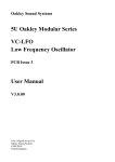
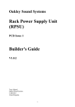
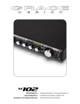
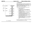
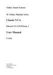
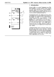
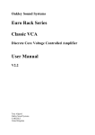
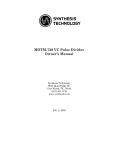
Oakley Sound Systems
5U Oakley Modular Series
VC-LFO
Low Frequency Oscillator
PCB Issue 2
User Manual
V2.0.04
Tony Allgood B.Eng PGCE
Oakley Sound Systems
CARLISLE
United Kingdom
The suggested panel layout of the issue 2 VC-LFO module. This is different to the older issue 1 VC-LFO panel in
that we lose a switch and gain an additional pot.
Introduction
This is the User Manual for the issue 2 VC-LFO 5U module from Oakley Sound.
This document contains an overview of the operation of the unit and all the calibration procedures.
For the Builder's Guide which contains information on how to construct the module from our PCB
and parts kits please visit the main project webpage at:
http://www.oakleysound.com/lfo.htm
For general information regarding where to get parts and suggested part numbers please see our
useful Parts Guide at the project webpage or http://www.oakleysound.com/parts.pdf.
For general information on how to build our modules, including circuit board population, mounting
front panel components and making up board interconnects please see our generic Construction
Guide at the project webpage or http://www.oakleysound.com/construct.pdf.
The issue 2 Oakley VC-LFO behind a natural finish panel.
The issue 2 VC-LFO Module
This is a versatile yet easy to use voltage controlled low frequency oscillator module that can also
be used as an audio VCO over a useful range.
The unit features sinusoid, sawtooth, ramp, triangle and square outputs. All are available
simultaneously. A sync input is available to reset the waveforms to a fixed point.
The module features two CV inputs. One is fixed at 1V/octave. The other CV input is controlled by
a single pot on the front panel. When the pot is turned right of its central position, the pot acts as a
normal attenuator; increasing the sensitivity of the CV input to a maximum of 0.5V/octave. Left of
centre, the pot will act in inverting mode. Fully anti-clockwise the input will respond to
-0.5V/octave.
A dual colour LED indicates the output status.
Power (+/-15V) is provided to the board either by our standard Oakley 4-way header or
Synthesizers.com header. Current draw is around 40mA
Specifications
The VC-LFO has an operating range of lower than 0.002Hz (one cycle every eight minutes) to over
14kHz from the front panel controls. The range can be extended with external CV inputs. The
maximum frequency of the VC-LFO is well over 25kHz.
Range of Frequency control: 17 octaves. eg. When the fine control is central the frequency pot can
vary the output from 0.016Hz (one cycle per minute) to 1.7kHz.
Range of Fine Frequency control: 6 octaves. eg. When the main frequency pot is central, the fine
control will vary the rate from 1Hz to 64Hz.
These frequencies can be altered over a limited range by the onboard trimmer, or more significantly
by a change in the master timing capacitor.
As an audio VCO the usable range that conforms to 1V/octave (to +/-2cents) is over five octaves
from approximately 32Hz to 1.2kHz. For accurate musical use above this frequency we recommend
that you use the Oakley VCO.
Sync input requires a fast rising gate exceeding 2.5V when active, or at least 2V peak pulse or
sawtooth (not ramp) waveform.
The VC-LFO Sync input
Synchronisation of oscillators can be quite confusing sometimes. Indeed, you will find many
different methods adopted by designers to get their oscillator cores to synchronise with an incoming
clock or other timing waveform. Each method produces different sonic effects and, although all
have their uses, no one method probably suits all needs.
I should clear up one thing first, the Oakley VC-LFO does not have a clock sync input. In my mind
a true clock sync input would lock your LFO waveform onto the incoming clock frequency or a
multiple of it. For example, if your clock sync input was 25Hz you may expect the LFO module to
produce a perfect triangle wave at a frequency of 25Hz. There are cases where a modulating source
of this type would be very useful, especially when wanting to sync your LFOs to the tempo of a
song.
However the Oakley VC-LFO possesses no such cleverness. It relies on what I call a hard reset of
the core. In truth most analogue VCOs and LFOs use this method – but each design will use
different ways of achieving this. Again, it is unlikely that any one design will fulfil all expectations.
The Oakley VC-LFO uses a triangle wave oscillator at the core of its circuitry. This type of core
produces a very good quality square wave for free and we use this to drive the square wave output.
The key thing to remember is that the square wave output is only positive when the voltage of the
triangle wave is falling in value, and only negative when the triangle wave is rising in voltage.
Valid sync pulses to the VC-LFO are any fast rising positive voltage of 2.5V or more. A typical
gate signal that goes from 0V to +5V when active is suitable. As is the sawtooth or square wave
output of your VCO, which typically moves from -5V to +5V. Ramp waveforms (inverted sawtooth
waveforms) which rise slowly cannot be used.
When a valid sync pulse is received the triangle waveform is immediately taken to zero volts
irrespective of where it was in its cycle. A very short time later it is allowed to free run again at its
own frequency again. The issue 2 VC-LFO module triangle output will always ramp downwards
from zero volts after a sync pulse has been received as shown in the figure above. The sync input
frequency has no effect on the frequency of the triangle wave – all it does is force the waveform to
zero for a brief moment.
The sine wave is obtained by waveshaping the triangle wave output. Thus it too follows the same
pattern of resetting to zero and continuing downwards immediately afterwards. We can see this in
the next picture:
Again we can see that the waveform always goes negative immediately after the sync pulse has
been activated. This is true even if the wave was heading upwards just before the sync pulse was
received.
Now with the sawtooth, ramp and square outputs the VC-LFO's sync function gets a little unusual.
Remember that the square wave's output is derived from the core and not from waveshaping the
triangle wave. When the core is reset it resets the squarewave too. But not to zero volts – it's more
complicated than that.
When a sync pulse is received the square wave output always goes to +5V. It stays there for one
quarter of the LFO's whole cycle. So if you have a frequency of 1Hz the total time for one LFO
cycle is one second. In this case after the sync pulse is received the square wave output will either
go to, or stay at, its high level state for exactly 0.25 seconds. It will then drop down to -5V and
continue oscillating at 1Hz. So what you get is apparently a ¼ of a cycle delay in the operation of
the synchronisation. This is not true though – what you are actually getting is the square wave
responding to the ¼ cycle downward ramp of the triangle wave immediately after the sync pulse is
received.
The sawtooth output behaves again in a slightly unusual but still very predictable manner. This is
because it is generated from combining a chopped up version of the triangle waveform with the
square wave. When the sync pulse is received the output will be immediately be reset to -2.5V. It
will then ramp downwards to -5V in the usual way of sawtooths. However, since it started its
descent at -2.5V it will fly upwards to +5V after only one quarter of an LFO cycle.
The ramp output is simply an inverted version of the sawtooth. So when it is synchronised the reset
point is +2.5V and it moves upwards at the speed determined by the LFO's own frequency to +5V
In audio terms it still sounds like hard synchronisation, although it does have different sonic
characteristics to our other VCO module. However, these effects should be considered when using
the module as a modulation source.
The above picture shows the sawtooth output. The sync pulse has been delivered just as the LFO's
sawtooth output is falling from +5V to -5V. The sync pulse resets the sawtooth output to -2.5V and
then the sawtooth output falls to its usual -5V lower point and continues to oscillate as if nothing
had happened.
I should add that all these images come from the soft oscilloscope in VAZ Modular VST plug in
and are therefore distorted by the sound card's DC filtering, analogue to digital converters and antialiasing filters. The real waveforms are considerably sharper and have less ringing.
Calibration
There are five trimmers, or presets as we used to call them in the UK, on the PCB. You do not need
any special equipment to set these correctly, but an oscilloscope is helpful for the STEP and a
digital tuner, or a VST tuner plug in, is very useful for setting the V/octave trimmer.
You should use a proper trimmer tool or a fine blade jeweller's screwdriver for adjusting the two
multiturn trimmers. Vishay and others make trimmer adjusters for less than a pound. The three
6mm round trimmers need a small electrician's screwdriver.
OFF and SHP: Plug the sine output into an amplifier and use your ears for this one. Set the VCLFO to make a lowish note, around 220Hz (A below middle C) will do. Adjust SHP until the sine
output sounds pure. Its shouldn’t be too buzzy or too hollow. Then go back and adjust the OFF
trimmer to get it really pure. You may need to bounce back and forth between the two trimmers
until you get a good sound. Its not essential to get this right, just set it so you get a nice sounding
output. It’s easier to do than to explain.
STEP: This one affects the sawtooth and ramp outputs. The easiest way to set this is to use an
oscilloscope, but you can set it by ear if you haven’t got one of these. If you have a ‘scope, then
monitor the sawtooth output. You’ll probably notice a small step, or glitch, halfway down the ramp
part of the wave. Set the VC-LFO quite high to say about 1kHz. Adjust STEP until the little glitch
disappears. It will reappear when the VC-LFO is operating at high frequencies because of the nature
of the circuit, but this is fine for our purposes.
If you have no ‘scope then you need to use a lowish frequency saw output (0.5Hz or so) to
modulate a VCO or oscillating VCF. You can use the 1V/octave input on the VCO or VCF. You
should hear a ‘pee-ooh’ sort of sound from the VCO or VCF as its frequency is swept downwards
by the VC-LFO’s output. If the STEP trimmer is set incorrectly, you’ll hear a little jump as the
frequency moves downward. Adjust the STEP trimmer so that the affect is minimised.
V/OCT: Use this to generate a perfect 1V/octave scaling. This trimmer will need to be adjusted
along with the fine and coarse pots on the front panel. You will need a scope, or a digital frequency
counter, or the best of all, a guitar/chromatic tuner. Some people use another keyboard or a
calibrated VCO and listen to the beats, but that can take longer.
Plug your midi-CV convertor or 1V/octave keyboard into the 1V/octave input of the VC-LFO. Play
a lowish note on the keyboard, then go two octaves higher. Adjust V/OCT until the interval is as
close as you can to two octaves.
We are only setting the interval and not the actual frequency. It does not have to be a perfect C
when C is being pressed on the keyboard. It could be an F or whatever. The main point is that we
are setting the musical gap between the notes. If you do need to alter the pitch of the VC-LFO to
help you, use the front panel controls only. Leave the TUNE trimmer until later.
For any interval, if you find the higher note is flat, then turn the V/OCT trimmer to make it flatter
still. This actually reduces the range between the two notes. Conversely, if you find your interval is
greater than an octave, turn the trimmer to make the top note even higher. I always adjust V/OCT
on the high note of any interval, and only adjust the front panel FINE FREQ pot on the lower note.
This will probably require some patience and plenty of twiddling of the front panel controls as well.
But you will get there. It should be remembered that this is a VC-LFO and not a audio VCO. Thus,
the circuit has been optimised for its low frequency operation and not keyboard scaling. I reckon the
design should be able to track over five octaves give or take a few cents. At higher frequencies,
above 1.2kHz or so, it will tend to go flat.
TUNE: This trimmer sets the operating frequency of the VC-LFO. You can set this so that the front
panel controls operate over your chosen range. There is no right or wrong setting, although if you
have more than one VC-LFO you may wish to make them both behave identically. I prefer to set
TUNE so that when the FREQUENCY pot is centralised, the output frequency is around 1Hz (one
cycle per second) when the FINE FREQ pot is at its minimum.
Final Comments
I hope you enjoy using the Oakley VC-LFO.
If you have any problems with the module, an excellent source of support is the Oakley Sound
Forum at Muffwiggler.com. Paul Darlow and I are on this group, as well as many other users and
builders of Oakley modules.
If you have a comment about this user manual, or have a found a mistake in it, then please do let me
know.
Last but not least, can I say a big thank you to all of you who helped and inspired me. Thanks
especially to all those nice people on the Synth-diy, Oakley-Synths and Analogue Heaven mailing
lists and those at Muffwiggler.com.
Tony Allgood at Oakley Sound
Cumbria, UK
© March 2010
No part of this document may be copied by whatever means without my permission.