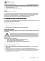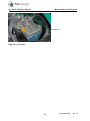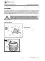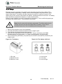
1
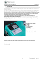
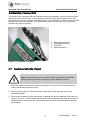
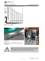
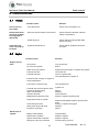
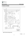
USER MANUAL SPRINTER & TRIKE Prins Maasdijk, Jan-12 CONTENTS 1. FOREWORD ............................................................................................... 2 2. IMPORTANT .............................................................................................. 3 3. GENERAL SAFETY REQUIREMENTS ................................................................... 4 4. OVERVIEW OF MACHINE AND CONTROLS .......................................................... 6 4.1 Overview of machine ..................................................................................... 6 4.3 Overview of controls ..................................................................................... 7 4.4 Overview of central dashboard......................................................................... 7 5 OPERATING THE FORKLIFT TRUCK ................................................................... 8 5.1 Adjustments ................................................................................................ 8 5.1.1 Steering column adjustment......................................................................... 8 5.1.2 Seat adjustment ......................................................................................... 9 5.2 Starting and stopping the engine ..................................................................... 10 5.3 Moving off and stopping the forklift truck ........................................................ 13 5.4 Optional ................................................................................................... 15 5.5 Manoeuvring ............................................................................................... 16 5.7. Loading and unloading of goods ..................................................................... 17 5.8 Use of the tow hook (Prins Sprinter only) ......................................................... 20 6 MAINTENANCE THE FORKLIFT TRUCK ........................................................ 21 6.1 Drive train .................................................................................................. 21 6.2. Engine ...................................................................................................... 22 6.2.1 Engine ................................................................................................... 22 6.2.2 Set-up for towing..................................................................................... 24 6.2.3 Cooling water system ............................................................................... 24 6.2.4 Fuel filter for Sprinter and Trike with diesel engine ........................................ 25 6.2.5 Air filter ................................................................................................ 27 6.2.6 Battery .................................................................................................. 28 6.2.7 Fanbelt ..................................................................................................... 29 6.3 Miscellaneous maintenance tasks..................................................................... 29 6.4 Electrical system .......................................................................................... 31 7. SUMMARY OF MAINTENANCE INTERVALS ........................................................ 32 8. TROUBLESHOOTING .................................................................................. 33 8.1 Vehicle ..................................................................................................... 33 8.2 Engine ...................................................................................................... 33 9 SPRINTER & TRIKE TECHNICAL SPECIFICATIONS ................................................ 36 10 ELECTRICAL CIRCUIT DIAGRAM ..................................................................... 38 Prins Maasdijk, Jan-12 Sprinter & Trike User Manual Prins Maasdijk, Jan-12 Sprinter & Trike User Manual Foreword 1. FOREWORD Congratulations on your purchase of a Prins Sprinter or Prins Trike forklift truck manufactured by Prins Maasdijk. You will find all the important information you need to operate and maintain your forklift truck in this manual. We recommend that you read through this manual carefully before taking the forklift truck into use. Anyone using the machine is also recommended to read carefully through the manual. Having read it, keep the manual where it can readily be found, so that essential information about maintenance, defects and so on is always to hand. If you need to order parts for your Prins forklift truck or if you have any questions or observations, please contact Prins Maasdijk. Please mention the machine's service and serial numbers in any correspondence with Prins Maasdijk. These numbers appear on the plates mounted at top left and right of the steering column. See Figure 1.1. Type plate (colour: black): 1. Make 2. Type 3. Serial number 4. Capacity 5. Deadweight 6. Year of construction Service plate (colour: grey): 1. Service number Figure 1.1 | Service number and serial number We trust you will enjoy many years of productive service from your new forklift truck. Prins Maasdijk 2 Prins Maasdijk, Jan-12 Sprinter & Trike User Manual Important 2. IMPORTANT This manual includes important information on the correct and safe use of your forklift truck. Follow the instructions set out in this manual at all times. At various points in this manual you will see the following symbol: Note! Important information. When you see this symbol, read the adjacent text carefully before starting the relevant operation. This information relates to the safety of yourself and others. Stay alert and prevent hazardous situations developing. 3 Prins Maasdijk, Jan-12 Sprinter & Trike User Manual General safety requirements 3. GENERAL SAFETY REQUIREMENTS When working with or servicing the forklift truck you must be aware of the associated hazards. Take full account of the safety rules. Failure to do so may result in serious physical injury to yourself or others. It is impossible for the manufacturer to foresee every hazardous situation that might arise. You as the user therefore have a responsibility to look out for your own safety and that of others during the use and maintenance of the forklift truck. Always use the tools and consumables recommended by the manufacturer. Only original components should be used as replacements. For your own safety and that of others: Never overload the forklift truck above the maximum permitted load indicated on the load chart (see also Figure 5.12) on the machine. Take careful note of the load diagram, which is located on the forklift truck's engine cover. If you are forced by circumstances to lift a load on a single fork, take into account that the maximal permitted load will be halved. However you must try to avoid doing this if at all possible. Keep the speed low when travelling with a load (never use top speed!) and keep the load as close as possible to the ground. With a raised load, keep the speed as low as possible and take account of the clearance height of the forklift truck. Complete the required safety checks on the machine before starting to work with it. You must never start work with the forklift truck without completing these checks. Particular attention should be paid to the tyres, the battery, the brakes, the steering system, the fuel system and the electrical components. This will help to prevent accidents. Fuel must never be added while the engine is running. No smoking is permitted while refuelling or while replacing or topping up the oil, and no open flames or sparks may be present in the immediate vicinity. Explosive gases are released during refuelling. Remove any spillages from the machine following refuelling or replenishment with oil. Before refuelling or replenishing the oil, check for any traces of leakage and establish where these are coming from. If they are the result of a technical defect, have this repaired before working with the forklift truck. Always apply the handbrake and place the gear lever in neutral when leaving the forklift truck. An incorrect sitting position can lead to accidents. You should therefore start by adjusting the seat so that you have good visibility and easy access to all controls. The forklift truck must never be used without the safety cage or the roll bar (fitted as standard). A safety belt must be used when the forklift truck is in operation. 4 Prins Maasdijk, Jan-12 Sprinter & Trike User Manual General safety requirements Always drive at a speed where you have the forklift truck under proper control. Excessive speed can be hazardous to you and your environment. Sudden braking, acceleration or turns can also result in a hazardous situation. When driving the truck in and out of areas with limited headroom, take account of the following points: o Always check that there is sufficient space above and alongside the forklift truck. o Keep all parts of your body within the safety cage at all times, keep your hands on the steering wheel and your feet on or close to the pedals. o Avoid hazardous situations when travelling. Operate the controls gently. This will appreciably extend the service life of your forklift truck and increase safety. Never allow anyone to walk beneath the loaded forks. This is extremely dangerous. Never carry passengers on the forklift truck, and do not use the forks to lift persons. Loads should be allowed to descend gradually, with the forks horizontal or tilted slightly back. Never lower the load with the forks tilted forwards. There are numerous signs you can use to check the condition of the machine. Unusual noises, vibration or changes in the response to the controls may indicate defects. If you suspect a fault, take the machine out of use and stop the engine. Check the cause of the defect and take the necessary measures to rectify it. Table 3.1 | Meaning of safety symbols Follow the safety and operating instructions Wear safety eyewear and protective clothing Smoking and open flames are prohibited Electrolyte is strongly corrosive Live electrics, avoid contact Areas where batteries are stored or charged must be adequately ventilated Risk of explosion, avoid short-circuits 5 Prins Maasdijk, Jan-12 Sprinter & Trike User Manual Overview of machine and controls 4. OVERVIEW OF MACHINE AND CONTROLS 4.1 Overview of machine Figure 4.1 | Overview 1 2 3 4 5 6 7 8 9 10 11 – – – – – – – – – Lifting mast Lifting cylinder Carriage load backrest Tilting cylinder Fork carriage Forks Front wheel Rear wheel (steered) Counterweight Ballast plates (separate) Safety cage 6 Prins Maasdijk, Jan-12 Sprinter & Trike User Manual 4.3 Overview of machine and controls Overview of controls 1. Combination switch driving direction, gear, horn 2. Battery switch (optional) 3. Parking brake switch 4. Front lighting switch (optional) 5. Rear lighting switch (optional) 6. Ignition switch Figure 4.2 | Control dashboard 4.4 Overview of central dashboard The Prins Sprinter and Prins Trike feature a central dashboard which includes a number of warning signals. The fuel gauge is located in the middle. This shows the fuel tank level for diesel engines. For lpg-driven machines, the level gauge is mounted on the tank. Below the fuel gauge is a counter registering the service hours during which the machine has been in operation. The following warning signals are displayed in figure 4.3. 1. 2. 3. 4. 5. 6. 7. Parking brake lamp Low oil pressure lamp Charging current indicator High coolant temperature Pre-glow indicator High gear indicator Low gear indicator Figure 4.3 | Signals 7 Prins Maasdijk, Jan-12 Sprinter& Trike User Manual Operating the forklift truck 5 OPERATING THE FORKLIFT TRUCK 5.1 Adjustments Adopt the correct seating position before starting the machine. 5.1.1 Steering column adjustment 1. Locked 2. Free Figure 5.1 | Steering column operation Rotate the lever to loosen it as indicated in Figure 5.1and place the steering column in a comfortable position. Then retighten the lever by moving it upwards. 8 Prins Maasdijk, Jan-12 Sprinter& Trike User Manual Operating the forklift truck 5.1.2 Seat adjustment The standard seat allows for longitudinal adjustment and adjustment of the angle of the back support. The various adjustment options are shown in Figure 5.2. Adjust the seat to provide a safe and comfortable sitting position. Figure 5.2 | Seat position Note! A safety belt must be worn at all times when operating the forklift truck. 9 Prins Maasdijk, Jan-12 Sprinter& Trike User Manual 5.2 Operating the forklift truck Starting and stopping the engine 1. Before starting the engine, ensure that the driving direction switch to the left of the steering column is in its neutral position (see Figure 5.3). For lpg driven machines the valve above the tank must be rotated to open it. 1. Forward 2. Neutral 3. Reverse Figure 5.3 |Driving direction switch 2. Turn the ignition key to position "I". The oil pressure and charging current lamps will both illuminate 0. I. II. III. Off Ignition on Pre-glow Start Figure 5.4 | Ignition key 2.1 Fork lift truck with diesel engine. Once both lamps are illuminated, the ignition key should be further rotated to position "II". The pre-glow lamp will now illuminate. Hold the ignition key in this position for around 5 seconds and then turn it on to position "III". The engine will now start. If you now release the key it will return to position "I" and the engine will continue to run. 10 Prins Maasdijk, Jan-12 Sprinter& Trike User Manual Operating the forklift truck Note! At very low ambient temperatures it may be necessary to pre-glow for longer than 5 seconds. Table 5.1 indicates how long pre-glowing should continue after the lamp is extinguished. Temperature Above 10°C Between -5°C and 10°C Below -5°C Maximal period of continuous pre-glowing Table 5.1 | Pre-glow times Additional pre-glow time Not required 5 seconds approx. 10 seconds approx. 20 sec. 2.2 Fork lift truck with lpg engine Once both lamps have illuminated, the ignition key should be rotated to position "III". the engine will then start. The "II" position has no function in the lpg models. 3. If the engine does not start within 10 seconds, then return the ignition key to the "OFF" position and wait 30 seconds before making a fresh attempt. Every fresh attempt should start from step 1. Note! The starter motor must not be allowed to operate continuously for longer than 20 seconds. 4. Once the engine is running, check that the oil pressure and charging lamps are extinguished. Where this is not the case, switch off the engine and check the following possible causes. Oil pressure lamp remains illuminated: o Is the V belt broken? o Is the oil filled to the correct level? o Is the oil in the sump contaminated? o Are there any short-circuits or other defects in the wiring? Charging current lamp remains illuminated: - Is the battery properly charged? - Is the battery acid level correct? - Are there any short-circuits or other defects in the wiring? If you have checked these items and identified no defects, please contact your dealer. 5. Allow the engine to come up to temperature by running it at half speed without load. 6. If you wish to stop the engine, ensure that the gear lever to the left of the steering wheel is in its neutral position. Also ensure that the forks are resting on the ground, in order to remove any unnecessary loading from the lifting cylinders and prevent accidents. Rotate the ignition key to the "OFF" position. 11 Prins Maasdijk, Jan-12 Sprinter& Trike User Manual Operating the forklift truck Note! Before dismounting from the truck the gear lever must be placed in its neutral position and the handbrake applied. It is now safe to dismount from the forklift truck. 7. If an lpg driven machine is not to be used for an extended period, for example at the end of the working day, the gas cylinder valve must be closed. 1. Shut-off valve 2. Level gauge Figure 5.5 | Lpg tank 12 Prins Maasdijk, Jan-12 Sprinter& Trike User Manual 5.3 Operating the forklift truck Moving off and stopping the forklift truck The Prins Sprinter and Prins Trike are provided with a hydrostatic drive which allows fully automatic driving. The direction of travel is selected using a selector switch on the steering column. 1. Forward 2. Neutral 3. Reverse Figure 5.6 | Direction selector switch Lift the selector switch gently and move it forwards or backwards to select forward or reverse travel. Operation of the accelerator will now move the machine in the desired direction. Where a change of direction is required, the machine must first be stopped, and the switch can then be moved to the appropriate position. Figure 5.7 | Gear selector switch The machine is provided with two gear positions, to allow a choice between additional speed and additional traction. The choice between the two speeds is made using a rotary switch on the steering column. It is not necessary to select first gear to drive away. It is recommended that the desired gear should be identified and selected before moving off. First gear can always be 13 Prins Maasdijk, Jan-12 Sprinter& Trike User Manual Operating the forklift truck selected by default. The maximal traction is then available. This will provide the best ride characteristics and the most constant speed of motion. Where long distances are to be travelled and the load will not be at or close to maximum, second gear may be selected. The speed of travel will then be increased. You must ensure that the conditions, such as the state of the road surface, will permit such higher speeds. It is possible to change the selected gear while moving at low speed. Always release the accelerator during gear changes. Changing gear can cause a minor jolt in the drive train. This will not harm the machine, but you must take account of possible effects on the load. The two gears are indicated on the central dashboard using symbols depicting a hare and a tortoise. 1. 2. Brake pedal Accelerator pedal Figure 5.8 | Pedals To bring the forklift truck to a stop, release the accelerator pedal and apply the brake pedal in a controlled manner until the machine comes to a complete halt. Once the machine is at a standstill, place the gear lever in its neutral position. The Prins Sprinter and Prins Trike with automatic gearbox come equipped with an inching pedal as standard. The machine is provided with an electrically operated parking brake. This is applied using a switch on the dashboard. An indicator lamp on the central dashboard will indicate whether the parking brake is switched on. When dismounting from the forklift truck the forks must always be fully lowered and the parking brake applied. The machine can not be driven away with the parking brake applied. 14 Prins Maasdijk, Jan-12 Sprinter& Trike User Manual Operating the forklift truck Figure 5.9 | Parking brake switch 5.4 Optional Figure 5.10 | accumulator switch The machine can be fitted with an accumulator as an option. This is brought into operation using the switch shown in Figure 5.10. The accumulator acts as a shock damper for the load carried by the forklift truck. For effective operation the accumulator must be set to the weight of the load being carried. You should contact the Prins Maasdijk technical department or your dealer with any queries about this system. The accumulator may be damaged beyond repair if it is overloaded. The accumulator must be switched off if travelling without a load or where the load carried is substantially (more than 25%) above the accumulator setting. The accumulator should also be switched off when precise positioning of the load is required. In some cases the position used for the accumulator switch may be used for a different optional function. Check what optional equipment is fitted to your truck before operating and using this control. 15 Prins Maasdijk, Jan-12 Sprinter& Trike User Manual Operating the forklift truck 5.5 Manoeuvring The Trike is equipped with twin pneumatic tyres as standard. These provide stability in bends. The Prins Sprinter and the Prins Trike are steered via the rear axle to provide the smallest possible turning circle. Be aware when steering that the rear end will swing out. Note! The rear end will swing out during manoeuvres. You must therefore always ensure that there is adequate space around the truck to allow safe manoeuvring. When driving account must be taken at all times of any load carried on the forks. Anticipate any unevenness in the road surface in good time, potholes and other obstacles may affect the stability of the truck. If stability is seriously affected the load may fall from the forks. Note! Unevenness of the road surface may interfere with the stability of the fork lift truck and give rise to a risk of the load falling from the forks. Do not make sharp turns at high speed, whether a load is carried or not. The fork lift truck may lose its stability and overturn. Note! Making a sharp turn at high speed, whether a load is carried or not, may affect the stability of the fork lift truck. Overturning the truck may cause damage and injury to yourself or others. 16 Prins Maasdijk, Jan-12 Sprinter& Trike User Manual Operating the forklift truck 5.6 Operation of mast and forks The forklift truck is equipped with two hydraulic functions as standard, the first to raise the load and the second to tilt the mast. In most cases the machine will also be equipped with a sideshift function to allow the load to be moved sideways. The installation of a fourth and even a fifth hydraulic function is also possible. The various functions are all controlled via a valve block located to the right of the driver. 1. 2. 3. 4. Raising and lowering Adjusting angle of tilt Side-shift Optional function Figure 5.11 | Hydraulic functions 5.7. Loading and unloading of goods Note! Ensure that the load is correctly stacked and balanced at all times. Falling loads may result in serious injury to the operator or others. 1. Place the forklift truck directly in front of the goods to be carried. Ensure that the load is evenly distributed between the forks. 2. Ensure that the mast is not tilted forwards or backwards, then bring the forks to the appropriate height. 3. Drive slowly forwards until the load comes up against the carriage backrest. Now raise the load by 5 to 10 cm. It may happen that the load is not completely at the edge of the trailer or storage racking. In that case you should insert the forks as far as possible and then raise them slightly. 17 Prins Maasdijk, Jan-12 Sprinter& Trike User Manual Operating the forklift truck Note! Ensure before raising the load that it is not tipping forwards. You must therefore always ensure that the forks are inserted 2/3 to 3/4 of the way into the load, depending on the weight of the load. 4. Now reverse a little, until the load is so positioned that it can be taken entirely on the forks. Lower the load again, then insert the forks fully until the load comes up against the carriage backrest, and raise the load some 5 to 10 cm. 5. Allow the forks to descend to just above the ground, say 10 to 20 cm. 6. Tilt the mast completely back and reverse cautiously away. 7. Drive with the load to the desired location. Note! Brake and steer with extreme care when driving with a load on the forks. Sudden changes of speed or direction may result in the loss of the load. 8. Having arrived at the desired location, bring the forks back to their vertical position, so that the load is level with the unloading location. 9. Allow the load to descend to around 5 cm above the unloading point. Drive gently forwards and place the load some 10 to 20 cm in front of the final resting place. 10. Now reverse a similar distance (10 - 20 cm), raise the load once again by some 5 cm and finally place it in its ultimate position. This latter manoeuvre is intended to prevent damage from forks protruding from the load to any obstacle which is invisible to the driver because of the load. 11. The Prins fork lift truck is provided with removable counterweight plates. Where lighter loads are being carried, a number of plates may be removed so as to reduce the weight of the machine. This may have advantages in dealing with difficult terrain and preventing tracks being created in the substrate. Where these matters are not an issue, ensure that all counterweight plates are in place. Procedure: 1. Establish the weight of the load to be carried 2. Consult the load table in Figure 5.12 to determine the minimal number of counterweight plates required. 3. Fit this number of plates. The fitting and removal of plates must always be carried out by two persons. 4. The weight of one pair of Prins Trike weights is equivalent to a single Prins Sprinter balance weight; the stated numbers (0 – 10) in the load table relate to single balance plates in the case of the Prins Sprinter, and pairs of balance weights in the case of the Prins Trike. 5. When the correct plates are in place, replace the securing components (see figure 5.13 for the Sprinter and figure 5.14 for the Trike). 18 Prins Maasdijk, Jan-12 Sprinter& Trike User Manual Operating the forklift truck Figure 5.12 | Load table Figure 5.13 | Prins Sprinter ballast plate securing components Figure 5.14 | Prins Trike ballast plate securing components Note! It is extremely hazardous to work with the machine with insufficient ballast plates in place. If there is any doubt, ALWAYS install the full total of ballast plates on the truck, and fit the securing components. 19 Prins Maasdijk, Jan-12 Sprinter& Trike User Manual Operating the forklift truck Note ! In the case of the Prins Trike the ballast plates are located below the rear engine cover, both on the left and right. The ballast weights must always be added or removed in pairs, one from the left and one from the right. The weight of a pair of Trike weights is equivalent to the weight of a single Sprinter weight. See Table 5.12. In case of doubt, ALWAYS fit the full number of ballast plates to the fork lift truck and secure these. 5.8 Use of the tow hook (Prins Sprinter only) The Sprinter is equipped as standard with a tow hook to allow other vehicles to be towed. Ensure in all cases that the vehicle to be towed can be towed safely. Always ensure that the securing pin is properly installed Note! Ensure that the tow hook securing pin is properly installed at all times! A towed vehicle which comes loose may cause injury and/or damage. The maximal load on the tow hook is 500kg. If the hook is loaded beyond this there is a risk of it breaking, which may result in damage to the vehicle. 20 Prins Maasdijk, Jan-12 Sprinter & TrikeUser Manual Maintaining the forklift truck 6 MAINTENANCE THE FORKLIFT TRUCK Good maintenance is vital for the safe operation and long service life of your forklift truck. Prins Maasdijk therefore strongly advise that the matters covered in this manual should be attended to, stringently and with care. The timing of the various operations is indicated in this manual. The prescribed times, indicated in hours, relate to the service hours for the truck, which are displayed on the counter on the dashboard. The indicated times are based on operation in normal circumstances. With heavy use or in extreme conditions, certain maintenance operations may need to be carried out with greater frequency. Note! The operations specified in this manual should only be carried out by competent persons familiar with the working procedures, who are aware of the safety requirements and the hazards that may be created if these are ignored. If you or your staff are not adequately aware of these requirements, have the maintenance work carried out by your dealer or the Prins Maasdijk Technical Department. 6.1 Drive train The Prins Sprinter and Prins Trike are provided with a so-called hydrostatic drive. This indicates that the drive is provided by means of hydraulic fluid, using a motor and pump. For proper operation and long service life it is crucial that the hydraulic fluid should be in top condition. The following instructions should therefore be followed precisely. Failure to follow the instructions correctly or contamination of the system may seriously reduce service life or lead to costly repairs. You are expressly advised to have work on the hydraulic system carried out exclusively by Prins Maasdijk. During the running-in period (the first 50 hours): 1. Check the transmission oil level using the dipstick (see no. 1 in Figure 6.1). Top up the oil if necessary (see no. 1 in Figure 6.1). 1. Dipstick 2. Oil filler opening 3. Oil filter Figure 6.1 | Hydraulic fluid 21 Prins Maasdijk, Jan-12 Sprinter & TrikeUser Manual Maintaining the forklift truck Note! Carry out the check while the engine is running but the machine is stationary, with the oil at operating temperature. 2. The transmission should be checked regularly for oil leaks. Following the running-in period (after 50 hours): - Replace oil filter (see no. 3 in Figure 6.1). Periodically: Every 200 hours: - Check the oil level in the transmission and top up where necessary. Every 500 hours: - Replace oil filter. Every 1000 service hours: - Replace the oil in the transmission. Note! Where the annual service hours are less than 1000 hours on an annual basis, the should be replaced every two years. Note! It is essential to prevent any contamination whatsoever entering the hydraulic system during level gauging or other work on the system. The tiniest particle of dirt can cause damage. Oil change data Capacity Tank : 70 litres 6.2. Engine 6.2.1 Engine The engine of your new Prins forklift truck will also require a period of running in. This will last around 50 hours. We now detail the actions required to maintain your forklift truck in optimal condition and prevent problems. On page 32 you will find a table setting out all the operations relating to the maintenance of the forklift truck. During the running-in period (the first 50 hours): 1. Check the oil level in the engine sump using the dipstick. Top up the oil if necessary (this also applies after the running-in period). 22 Prins Maasdijk, Jan-12 Sprinter & TrikeUser Manual Maintaining the forklift truck Note! Carry out this check before starting the engine, or wait at least 5 minutes after switching off the engine. 2. The engine should be checked regularly for oil leaks. Following the running-in period (after 50 hours): 1. Replace the oil filter. 2. Replace the engine oil. Replacing the oil filter: o Remove the old filter (see Figure ) with the aid of a filter wrench. o Apply a film of oil to the new filter's oil seal. o Screw in the filter hand tight. o Once the filter is in place the oil level will usually drop slightly. Check first that the filter is not leaking, and if necessary top up the oil. 1. Oil filter Figure 6.2 | Oil filter, Sprinter & Trike with diesel engine 3. Replace the oil. First allow the old oil to run out of the sump via the drainage point below the engine. Periodically: Every 200 service hours: 1. Replace the oil filter. 2. Replace the oil. Oil change data Capacity Sump: 4 litres Oil ELF Multi-performance 3C 15W40 or to MIL-L-2104C or API classification CD class or above 23 Prins Maasdijk, Jan-12 Sprinter & TrikeUser Manual Maintaining the forklift truck 6.2.2 Set-up for towing If it is required to tow the vehicle, the bolt above the hydraulic pump should be loosened a few turns so that hydraulic lines 2 and 3 are interconnected, freeing the wheels. This action must be carried out while the engine is running. 1. Bolt for towing set-up 2. Hydraulic line 3. Hydraulic line Figure 6.3 | Bolt for towing set-up 6.2.3 Cooling water system It is important to keep the coolant level topped up. Failure to do so may lead to overheating, causing damage. The coolant level should therefore be topped up daily. The procedure is as follows. Note! Always wait for the engine to cool down before opening the coolant reservoir. 1. Open the cooling water system filler cap slightly to allow any over-pressure to dissipate. Figure 6.4 | coolant filler opening 24 Prins Maasdijk, Jan-12 Sprinter & TrikeUser Manual Maintaining the forklift truck 2. Now remove the filler cap completely and check that the coolant is at the indicated level, roughly halfway up the reservoir. 3. Top up as necessary. 4. Replace the filler cap tightly after topping up. Coolant We recommend ELF COOLELF. The cooling water is cooled by air flowing through the radiator. Check at least weekly that the airflow across the radiator is adequate. The radiator may become blocked, particularly when working in dirty or dusty conditions and cooling capacity will be seriously affected. Contamination may be blown out of the radiator using compressed air. 6.2.4 Fuel filter for Sprinter and Trike with diesel engine The fuel filter must be replaced every 200 hours as a minimum, or at least once a year. The fuel filter is located in the engine compartment. Fuel filter replacement: o Remove the old filter using a filter wrench. o Apply a smear of fuel to the new filter's oil seal. o Fill the filter with clean fuel. o Screw in the filter hand tight. o Bleed the system in accordance with the following procedure. Bleeding the fuel system It is sometimes necessary to bleed air out of the system to prevent damage to the engine or its components. Note! The fuel system must not be bled while the engine is still warm. Doing so may present a risk of fire or explosion. The evaporating fuel may also give rise to toxic vapours. When may bleeding be necessary? o If any of the fuel system pipework has been broken into o If the fuel tank has been completely emptied o If the engine has been out of service for an extended period o If the fuel filter has been replaced. The procedure for air bleeding is as follows: 1. Fill the fuel tank with diesel. 2. Loosen the air bleed screw (see Figure 6.5) above the fuel filter. 3. Start the engine and wait until fuel trickles out through the bleed orifice, then retighten the bleed screw. 4. Start the engine. It may run unevenly at first, but this will stabilise after a short time. 5. The starter motor must not be allowed to run continuously for more than 20 seconds during this bleeding period. If the engine fails to start in this time, wait for half a minute before operating the starter motor again. 25 Prins Maasdijk, Jan-12 Sprinter & TrikeUser Manual Maintaining the forklift truck 1. bleed screw Figure 6.5 | Fuel filter 26 Prins Maasdijk, Jan-12 Sprinter & TrikeUser Manual Maintaining the forklift truck 6.2.5 Air filter The purpose of the air filter is to clean the air entering the engine. This is a dry filter which is not suitable for use with oil. The filter must be replaced once annually, or every 600 service hours. In dirty or dusty conditions it may be necessary to reduce this interval. Where necessary the filter may be blown clean, however this must always be done from the inside outwards, with a maximum air pressure of 5 bar. Note! It is extremely important that the filter element is properly seated when it is replaced in the filter housing. If it vibrates loose in operation, dust will be able to enter the engine, causing damage (see Figure 6.6 and Figure 6.7). Figure 6.6 | Air filter 1. Air filter housing 2. Air filter element 3. Fixing nut 4. Discharge valve for dirt Figure 6.7 | Blowing air filter element clean 27 Prins Maasdijk, Jan-12 Sprinter & TrikeUser Manual Maintaining the forklift truck 6.2.6 Battery Electrical energy is required, for the starter motor and other functions of the vehicle. This electrical power is delivered by a battery, which is itself charged by a dynamo driven by the engine output shaft. The battery may fail to operate correctly for a variety of reasons. The cables may not be correctly connected to the battery, possibly because of corrosion. The battery posts should be smeared with Vaseline or similar to prevent this. Another cause of failure is low level of electrolyte in the battery. This is rectified by topping up the battery with distilled water. The procedure is as follows. Note! Avoid contact with the battery electrolyte! The dilute sulphuric acid solution can burn the skin and make holes in clothing. In the case of accidental exposure, flush immediately with flowing tap water. 1. 2. 3. 4. Remove the protective cover from the battery. The cable should then be disconnected from the negative pole. The positive pole should then be disconnected. Open the filler opening and check the fluid level. Top up if necessary (see Fout! Verwijzingsbron niet gevonden. and Fout! Verwijzingsbron niet gevonden.). 5. When reconnecting the battery, the positive pole must be connected first, followed by the negative pole. Figure 6.8 | The battery Figure 6.9 | The battery acid level 1. filler cap A. Maximum level B. Minimum level 1. Level too low 2. Level okay 3. Level too high 28 Prins Maasdijk, Jan-12 Sprinter & TrikeUser Manual Maintaining the forklift truck 6.2.7 Fanbelt The fanbelt or V-belt provides drive to the fan and the dynamo. If it is not adequately tensioned it will slip. This will impair the function of the fan, which is responsible for cooling the engine block. The engine may then overheat. The same applies to the dynamo: if the belt is loose it will not operate correctly and the battery will not be properly charged. This may cause problems, for example with starting. The V-belt must therefore always be correctly tensioned. Checking this is fairly straightforward. Note! Ensure that the engine is switched off when checking the V-belt. 1. Press with a finger on the middle of the section of V-belt between the dynamo and the crankshaft. The deflection of the V-belt from its original position must not be less than 7 mm or more than 9 mm. 2. If it is outside these limits, loosen the two dynamo securing bolts. 3. Position the dynamo in such a way that the V-belt is at the correct tension and retighten the bolts. 1. Fan belt (V-belt) 2. Adjusting bolts 3. Play 7 – 9 mm Figure 6.10 | Tensioning the V-belt 6.3 Miscellaneous maintenance tasks Lubrication The following components must be greased at least once monthly: o Side-shift cylinder o Steering cylinder o Axle tipping component o Tilting cylinders Tyres The tyre pressure must be checked weekly. The correct tyre pressures are: o Driven (front) wheels : 3.0 bar o Steered (rear) wheels : 2.5 bar 29 Prins Maasdijk, Jan-12 Sprinter & TrikeUser Manual Maintaining the forklift truck The tyre valves are located at the edge of the rims. On machines fitted with double pneumatic tyres (optional on the Prins Sprinter, mandatory on the Prins Trike), the valve for the inner tyre is on the edge of the inner rim, closest to the chassis. Raise the mast to its maximum height and look from the front to see if the valve is accessible. If necessary, drive the machine a little forwards or backwards in order to gain access to the valve. Figure 6.11 | Valve on inner edge of rim Figure 6.12 | Valve on outer edge of rim Note! With double pneumatic tyres, the pressure in the outer tyre should always be at least 0.5 bar higher than that in the inner tyre. 30 Prins Maasdijk, Jan-12 Sprinter & TrikeUser Manual Maintaining the forklift truck 6.4 Electrical system The machine is provided with a 12V electrical system, with an alternating current dynamo. Apart from the procedures described in relation to the dynamo, the electrical system is in principle maintenance-free. However, dirt and moisture may affect the function of the system. Avoid directing a stream of water onto electrical components when cleaning the machine. Also avoid exposure of the electrical components to dirt and moisture as far as possible. The electrical system includes a fusebox located to the right of the steering column. In the event of a fault, always check first that a fuse has not burned out. Always engage a competent electrician to deal with any necessary repairs to the electrical system. 1. Connection 15 2. Dashboard + 3. Selector switch/Parking brake/ high and low gears 4. Battery 5. Flashing indicators 6. Connection 30 7. Horn 8. Front working light/parking lights 9. Rear working light/dipped beam 10. Dipped beam 11. Headlamp Figure 6.13 | Fuses 31 Prins Maasdijk, Jan-12 Sprinter & Trike User Manual Summary of maintenance intervals 7. SUMMARY OF MAINTENANCE INTERVALS In Table 7.1 and Table 7.2 below you will find a summary of the operations required for the maintenance of your fork lift truck. Table 7.1 | Hydraulic drive Operation Replace oil Replace filters Running-in period First 50 hours Every Every 500 hours 1000 hours X X X Every year Every 2 years X X Daily checks on oil levels and for leaks. Table 7.2 | Engine Operation Replace oil Replace oil filter Replace air filter 1) Check V-belt tension Replace fan-belt Check battery electrolyte level Check coolant and engine oil levels Replace fuel filters 2) Running-in Before period each First 50 use hours After 50 hours After 50 hours Every 100 hours Every 200 hours Every 600 hours Every year X X X X X X X X X X X X Check oil level daily 1) Or earlier if necessary 2) Coarse and fine filter 32 Prins Maasdijk, Jan-12 Sprinter & Trike User Manual Fault analysis 8. TROUBLESHOOTING 8.1 Vehicle Possible cause Solution Loss of front or rear lamps . Fuse burned out Check fuse, see Figure 6.13. Forklift truck does not move off when inching pedal is depressed . Direction selector switch not turned on. Check if the drive direction selector switch is switched on . Cable hangs up Check that the inching pedal cable returns correctly. . Hydraulic fluid level low Check that the hydraulic fluid level is correct. Truck does not come correctly up to speed 8.2 Engine Engine will not start Possible cause Solution · Lack of fuel · Air in the fuel system Top up fuel tank Bleed · Water in the fuel system · Fuel line blocked · Fuel filter blocked Replace fuel and repair or replace fuel system Clean fuel line Clean or replace filter Use specified fuel or engine oil · Excessive fuel viscosity or engine oil at low temperature Starter fails to operate · Fuel cetane content too low Use specified fuel · Fuel leak due to loose injector lines · Incorrect injection timing · Worn fuel camshaft · Atomiser blocked · Malfunctioning injection pump Tighten nut . Compression leak in cylinder · Valve timing incorrect · Worn piston rings and lining · Excessive valve play Replace head gasket, tighten cylinder head bolts Rectify or replace timing gear Replace Adjust · Battery is discharged · Starter fails to operate · Ignition switch fails to operate · Wiring not correctly connected Charge battery Repair or replace Repair or replace Connect wiring correctly 33 Adjust Replace Clean atomiser Repair or replace injection pump Prins Maasdijk, Jan-12 Sprinter & Trike User Manual Engine runs unevenly White or blue exhaust gases Grey or black exhaust gases Output capacity low Excessive oil consumption Fault analysis · Fuel filter blocked or dirty · Air filter blocked Clean or replace Clean or replace · Fuel leak due to loose injector lines · Injection pump fails to operate correctly Tighten nut Repair or replace · Incorrect atomiser opening pressure · Atomiser defective or blocked · Regulator fails to function correctly Adjust Repair or replace Repair · Excessive engine oil Reduce to specified level · Worn or defective piston rings and lining · Incorrect injection timing Repair or replace Adjust · Excessive loading · Fuel level too low · Fuel filter blocked · Air filter blocked Reduce loading Fill to specified level Clean or replace Clean or replace · Incorrect injection timing · Irregular fuel injection · Atomiser pressure too low Adjust Repair or replace injection pump Repair or replace atomiser · Compression leak Replace head gasket, tighten cylinder head bolt, glow plug or atomiser mounting · Piston ring openings all on same side · Oil seal worn or defective · Piston ring groove worn · Worn valve stem/valve guide Change position Replace Replace piston Replace Fuel contaminated with engine oil · Worn injection pump piston · Defective injection pump Replace pump element or entire pump Replace Water contaminated with engine oil · Defective head gasket · Cracked cylinder block or cylinder head Low oil pressure · Insufficient engine oil · Blocked oil filter · Excessive play in crankshaft bearing · Excessive play in connecting rod bearing · Excessive play in rocker shaft bearing · Oil channel blocked · Incorrect oil type 34 Replace Replace Top up Clean filter Replace Replace Replace Clean Use specified oil Prins Maasdijk, Jan-12 Sprinter & Trike User Manual Excessive oil pressure Engine overheating Fault analysis · Defective oil pump Repair or replace · Incorrect oil type Use specified oil · Insufficient engine oil · V-belt snapped or incorrectly tensioned · Insufficient coolant · Blocked radiator grille or radiator vanes · Internal corrosion to radiator · Corroded coolant line · Defective radiator cap · Excessive loading · Head gasket defective · Incorrect injection timing · Unsuitable fuel used (mixed with petrol) Top up engine oil Battery discharges rapidly · Insufficient electrolyte · Slipping V-belt · Wiring not correctly connected · Voltage regulator defective · Dynamo defective · Battery defective 35 Replace or tension correctly Top up coolant Clean Clean or replace Clean or replace Replace Reduce loading Replace Adjust Use specified fuel Top up with distilled water and charge battery Tension or replace V-belt Connect wiring correctly Replace Replace Replace Prins Maasdijk, Jan-12 Sprinter & Trike User Manual 9 Technical specifications SPRINTER & TRIKE TECHNICAL SPECIFICATIONS Table 9.1 | Technical specifications Sprinter Model Type Lifting capacity Weight (unladen) without ballast plates Weight (unladen) with ballast plates Centre of gravity of load Mast inclination, front/rear Fork carriage type Transmission Fuel Engine manufacturer Engine model Engline capacity Speed kg kg kg mm kW km/h Diesel 1000 2080 1480 Trike LPG 1000 2080 1480 500 7°/7° FEM 2b Hydrostatic Diesel Gas Kubota Kubota D1105E DF972ES 19 22 26 26 Diesel 1000 1940 1660 500 LPG 1000 1940 1660 7°/7° FEM 2b Hydrostatic Diesel Gas Kubota Kubota D1105E DF972ES 19 22 26 26 Table 9.2 | Dimensions Model Front tyres Rear tyres A mm B mm C mm D mm E mm F mm G mm H mm I mm J mm K mm L mm Sprinter Trike 295/50R15 24x13-12 1780 1480 480 1250 2150 680 340 260 1170 2140 1295 2600 295/50R15 24x13-12 1780 1480 480 1600 2360 680 360 260 1170 2140 1295 2280 36 Prins Maasdijk, Jan-12 Sprinter & Trike User Manual Technical specifications 37 Prins Maasdijk, Jan-12 Sprinter & Trike User Manual Electrical circuit diagram 10 ELECTRICAL CIRCUIT DIAGRAM Diagram 10.1 | Electrical circuit diagram, cable loom Prins Maasdijk, 38 Jan-12 Sprinter & Trike User Manual Electrical circuit diagram Diagram 10.2 | Dashboard electrical circuit diagram Prins Maasdijk, 39 Jan-12