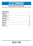
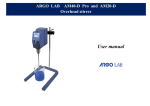
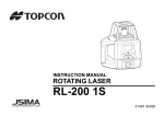
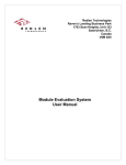
1
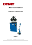
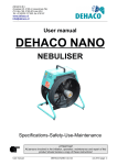
Assembly Manual Enmix Agitator-Mixer Version 2.4 february, 2015 Van der Ende Pompen B.V. +31174515050 Maasambacht 4 2676CW Maasdijk The Netherlands Foreword This assembly manual is intended for use by technicians who are qualified to install this type of machine. It is not a user manual. The Enmix has no real function when it is not connected to the appropriate facility for this installation and consequently it is classified as an unfinished machine. This assembly manual contains only those instructions pertinent to the safe assembly, correct installation and safe operation of the Enmix. It does not contain operating instructions for the entire installation. The approved installer should provide these. Each chapter is numbered and, where appropriate, the chapters are divided into sections. The table of contents on page 3 gives an overview of the chapters and sections and a reference to the appropriate page number. A number between parentheses behind a component refers to the part number as shown in Figure 1, 3 or 4. Assembly manual Enmix Page 2 of 23 Van der Ende Pompen B.V. +31174515050 Maasambacht 4 2676CW Maasdijk The Netherlands Table of Contents Foreword ......................................................................................................................................................................................................2 Table of Contents ......................................................................................................................................................................................3 1. Identification ..........................................................................................................................................................................................4 1.1 General ..............................................................................................................................................................................................4 1.1.1 Description of the machine .............................................................................................................................................4 1.1.2. Specifications ........................................................................................................................................................................4 1.2 Schematic diagram of the machine .......................................................................................................................................5 1.3 Operation .........................................................................................................................................................................................5 1.4 Users...................................................................................................................................................................................................6 1.5 Use .......................................................................................................................................................................................................6 1.6 Media..................................................................................................................................................................................................6 1.7 Operating environment .............................................................................................................................................................6 1.8 Guarantee provisions..................................................................................................................................................................7 1.9 CE mark .............................................................................................................................................................................................8 1.10 Residual risks ..............................................................................................................................................................................8 2. Description ..............................................................................................................................................................................................9 2.1 Operating principle......................................................................................................................................................................9 2.2 General ..............................................................................................................................................................................................9 2.3 Transport and storage ................................................................................................................................................................9 2.4 Components ................................................................................................................................................................................. 10 3. Safety instructions ............................................................................................................................................................................ 13 4. Assembly ............................................................................................................................................................................................... 14 4.1 General ........................................................................................................................................................................................... 14 4.2 Installation instructions ......................................................................................................................................................... 14 4.3 Delivery checklist ...................................................................................................................................................................... 15 4.4 Assembly ....................................................................................................................................................................................... 16 4.5 Installation.................................................................................................................................................................................... 17 4.6 Connecting / start-up .............................................................................................................................................................. 18 5. Use ........................................................................................................................................................................................................... 19 6. Maintenance ........................................................................................................................................................................................ 20 6.1 Regular checks ............................................................................................................................................................................ 20 7. Malfunctions ........................................................................................................................................................................................ 21 8. Declaration of Conformity ............................................................................................................................................................. 22 Appendices ............................................................................................................................................................................................... 23 Assembly manual Enmix Page 3 of 23 Van der Ende Pompen B.V. +31174515050 Maasambacht 4 2676CW Maasdijk The Netherlands 1. Identification This overview contains general information about the machine. The aim of this document is to define the purpose, the overall functioning and the application field of the machine. 1.1 General 1.1.1 Description of the machine The Enmix consists mainly of four components: A. Drive unit - an electric motor with a reduction gearbox B. Drip plate – for the event of oilspilling from the gearbox C. Frame - a custom-made stainless steel tubular frame D. Mixer - a long shaft with keyway and mixing blade, made entirely of stainless steel E. Shaft guide - a guide for the mixer (only if the mixer shaft is longer than one metre) The purpose of the machine is to keep liquids in motion in order to promote their dissolution and prevent precipitation. The relatively low rotational speed prevents foam formation. The Enmix drive unit must be mounted above a liquid reservoir such that the mixing blade will continue to rotate below the surface of the liquid up to the lowest liquid level. Starting from April 2012, the Enmix is equipped with a drip plate for the event of oilspilling from the gearbox. This prevents oil from getting into the irrigation water. 1.1.2. Specifications Type Motor power Motor revolutions Mixer revolutions Reduction ratio Supply voltage Sealant Condenser Material Tabel 1. Specifications * = only with 75 cm mixing blade Enmix agitator-mixer 0.37 kW 1410 rpm at 50Hz power supply 1550 rpm at 60Hz power supply 94 rpm at 50Hz power supply 104 rpm at 60Hz power supply 15:1 230 Vac 50Hz (incl. thermal protection) 220 Vac– 240 Vac 60 Hz* (incl. thermal protection) 400 Vac available (excl. thermal protection) IP55 12 µF Stainless steel 304 (stainless steel 316 optional) Assembly manual Enmix Page 4 of 23 Van der Ende Pompen B.V. +31174515050 Maasambacht 4 2676CW Maasdijk The Netherlands 1.2 Schematic diagram of the machine Diagram of the main components (the letters correspond to their respective component). A B C D E Figure 1. Schematic drawing of the Enmix Letter Description A. Drive unit - electric motor with reduction gearbox B. Oil drip plate C. Frame - stainless steel tube D. Mixer - shaft with keyway and mixing blade E. Shaft guide (only when the mixer shaft is longer than one metre) Table 2. Main components of the Enmix 1.3 Operation The Enmix is supplied without controls. The Enmix 230 Vac version is supplied with locking thermal protection and with approximately two metres of cable. The Enmix must be connected to a switched socket outlet or a timer to operate the machine. The 400 Vac version does not include cable or thermal protection. These should be provided by the approved installer. The 230 Vac version includes a reset button on the terminal connection box for the thermal protection device. Assembly manual Enmix Page 5 of 23 Van der Ende Pompen B.V. +31174515050 Maasambacht 4 2676CW Maasdijk The Netherlands Reset thermal protection Figure 2. Location of the reset button 1.4 Users Intended users are at least 18 years of age, employed by the company where the Enmix is installed and appointed by the management as the competent and qualified person to operate the Enmix. Unintended users are users who do not meet the above requirements. Unintended users are all users who, by using the Enmix, create unsafe situations or cause danger to themselves and/or others. 1.5 Use The Enmix is intended to be used for the mixing and continuous agitation of liquids containing additives. To achieve this, the Enmix must be placed above a liquid reservoir with the mixing blade in the liquid. The Enmix is not intended to be used without being placed on a liquid reservoir. The Enmix is not intended to be used for the purpose of processing foodstuffs. 1.6 Media In connection with the chemical resistance properties of the materials which make up the Enmix, the Enmix cannot and must not be used in just any medium. The manufacturer should be contacted for questions and advice in this matter. Upon request, the manufacturer can also provide a list of suitable and unsuitable chemicals. Under no circumstances may the media contain long fibres (longer than 5mm), neither may viscous media (>1000 mPas) be mixed with the Enmix machine. The supplier or the manufacturer should be contacted for advice on the use of media and the Enmix in general. Should the standard stainless steel type 304, of which the Enmix is composed, prove to be insufficiently resistant to certain media, the mixer shaft and the mixing blade are also available in stainless steel type 316. 1.7 Operating environment The Enmix is intended for use as a mixer on a liquid reservoir. When installing the mixer, care should be taken to ensure there is sufficient free space around the Enmix. The Enmix must be mounted on the liquid reservoir. The Enmix is not intended for use in explosive surroundings. Assembly manual Enmix Page 6 of 23 Van der Ende Pompen B.V. +31174515050 Maasambacht 4 2676CW Maasdijk The Netherlands 1.8 Guarantee provisions This product is guaranteed for a period of 6 months from the proven date of commissioning, with a maximum date of 2 years after the date of production. The proven date of commissioning means the date on which the machine was installed. If a claim is made on the guarantee, the parts in question must be submitted to the manufacturer for evaluation. The guarantee will cease to be valid if one or more of the following conditions apply: Improper use or installation Repeatedly ignoring the advice of the manufacturer and/or the supplier Repair, maintenance or use by unauthorised persons Use of unsuitable connections with regard to power supply or cables Use of the machine in an unsuitable environment Intentional damage or adaptations to the machine The guarantee conditions conform to the METAALUNIE CONDITIONS (the Dutch organisation for small and medium-sized enterprises in the metal industry) published in January 2008. Assembly manual Enmix Page 7 of 23 Van der Ende Pompen B.V. +31174515050 Maasambacht 4 2676CW Maasdijk The Netherlands 1.9 CE mark The CE mark relates to compliance with the Machinery, Low Voltage, EMC and PED Directives. The Enmix is an unfinished machine and consequently does not meet all the conditions and essential safety requirements at the time of delivery. A list of the conditions and safety requirements that the Enmix does not meet at the time of delivery may be obtained from the manufacturer. The CE mark can be found on the sticker affixed to the motor. According to the Low Voltage Directive, the Enmix is classified as a Class I device. 1.10 Residual risks It is practically and economically impossible to cover all risks for the full 100%. Furthermore, one of the risks of the machine may be closely connected to its functionality. The so-called residual risks are shown in the table below. It is important that the user is aware of the risks involved when using this machine. All safety regulations should be followed in order to minimise the risks as much as possible. Risk page No. 1. Residual risk description If the mixer is longer than the support legs, which may or may not be present, the Enmix cannot be placed in a stable position. This is only applicable prior to the installation of the Enmix. Table 3. List of residual risks Risk factor Category 1 A Assembly manual Enmix Page 8 of 23 Van der Ende Pompen B.V. +31174515050 Maasambacht 4 2676CW Maasdijk The Netherlands 2. Description This chapter contains an explanatory description of the machine, which is the background information that is required to correctly and safely use the machine. 2.1 Operating principle The Enmix construction comprises a tubular frame (8). This frame is made to each customer’s specifications, whereby the dimensions of the liquid reservoir in particular are the determining factor. The depth of the reservoir and the shape also greatly determine the construction. The frame is placed on, above or even in (to some extent) the liquid reservoir. The material used is predominantly stainless steel tubing, type 304, 40x40mm. When working with low pH values (under pH4) or with other chemicals that could affect stainless steel type 304, stainless steel type 316 can be used for the mixer shaft and the mixing blade. The reduction gearbox (3) of the motor (6) and the shaft guide (9) are mounted on the frame. The function of the shaft guide is to prevent buckling, vibration and oscillation of long mixer shafts. The shaft guide is only used when mixer shafts are longer than one metre or in special cases. The electric motor is attached to the reduction gearbox and has no additional support. The mixing shaft (10) runs through the shaft guide and into the hollow shaft of the reduction gearbox where it is attached via a key connection. The mixer shaft is secured at the top by a bolt in an axial direction (14). A PVC cap (2) is placed over the shaft to keep out coarse dirt and dust. The shaft guide consists of a Teflon sleeve. A special bracket is welded to the frame for the purpose of attaching the shaft guide. If no shaft guide is required, this bracket need not be affixed. Since it concerns a 230 Vac electric motor with just one phase (as opposed to a three-phase motor), a capacitor (13) is fitted. The 400Vac version is not fitted with a capacitor. 2.2 General The rotation of the mixer shaft and the mixing blade sets the liquid in the reservoir in motion. The helical shape of the mixing blade not only rotates the liquid, it also pushes it upwards, or even downwards. The rotational direction (as seen from above) is normally clockwise. The best rotational direction should be decided in each situation. In almost all cases, the standard rotational direction is sufficient, however, if the reservoir is relatively small and has reinforcement ribs, the rotational direction may have a positive impact on the performance. Prior to making any adjustments, please always contact the supplier. 2.3 Transport and storage The Enmix is not transported or stored in special packaging but delivered in parts and assembled at the end-user by an approved installer. When storing the Enmix, care must be taken not to allow the mixer shaft and, where appropriate, the shaft guide to bend. Assembly manual Enmix Page 9 of 23 Van der Ende Pompen B.V. +31174515050 Maasambacht 4 2676CW Maasdijk The Netherlands 2.4 Components Below are the main components of the Enmix, represented by a number and corresponding name. 1 5 2 6 3 4 7 8 9 10 11 Figure 3. Overview of components Enmix I Number Description 1. Reset button for the thermal protection 2. PVC protection cap 3. Reduction gearbox 4. Mounting bolts (8x) 5. Connection cable (including plug) 6. Electric motor 7. Drip plate for oilspillings 8. Frame 9. Shaft guide (only when the mixer shaft is longer than 1m) 10. Mixer shaft (various lengths available) 11. Mixing blade (various lengths available) Table 4. Overview of components Enmix I Assembly manual Enmix Page 10 of 23 Van der Ende Pompen B.V. +31174515050 Maasambacht 4 2676CW Maasdijk The Netherlands 14 12 15 13 16 17 18 Figure 4. Overview of components Enmix II (PVC protection cap and junction box cap removed). Number Description 12. Terminal box Conduit cable gland 13. Capacitor 14. Lock bolt (M10) 15. Spring washer (M10) 16. Plain Washer (M10) 17. Indication mixing blade rotation 18. NBR rubber ring (50x30x3) Table 5. Overview components Enmix II Note: In special cases, the rotational direction can be adjusted. This should, however, be done in consultation with the manufacturer. Assembly manual Enmix Page 11 of 23 Van der Ende Pompen B.V. +31174515050 Maasambacht 4 2676CW Maasdijk The Netherlands Figure 5. Overview Enmix. Assembly manual Enmix Page 12 of 23 Van der Ende Pompen B.V. +31174515050 Maasambacht 4 2676CW Maasdijk The Netherlands 3. Safety instructions Please read this assembly manual carefully and ensure that you observe the safety instructions before installing or using the Enmix. The Enmix may only be used within the application areas for which it has been designed. The Enmix has been designed to operate as a mixer for a system in which liquid media are used. These media may only contain chemical substances that are compatible with the materials of the Enmix components that come in contact with them. Further information on the application areas can be found under paragraphs 1.5, 1.6 and 1.7. Work on the machine or installation of the electrical part of the Enmix may only be carried out by qualified personnel. Make sure the power supply is connected to a final circuit with an earth connection with a maximum fuse value of 16A and a circuit breaker with residual current of 30mA. Add solids gradually to prevent blockage of the mixing blades. Always follow all assembly and safety instructions. Failure to observe these instructions may cause serious damage to persons or property. Assembly manual Enmix Page 13 of 23 Van der Ende Pompen B.V. +31174515050 Maasambacht 4 2676CW Maasdijk The Netherlands 4. Assembly 4.1 General The Enmix is an unfinished product, and consequently the manufacturer cannot install all the required safety devices such as control logic or an emergency stop. It is, therefore, important that the approved installer takes care of these requirements. 4.2 Installation instructions Please make sure that the Enmix is out of reach of children at all times. Advice with regard to dosage rates and types of fertilizer should be obtained from your supplier. Place the Enmix on a flat, stable surface. Make sure that the Enmix is firmly attached to the fertilizer bin. Make sure at all times that the mixing blade can rotate freely. Make sure that contact with the agitator-mixer is prevented by placing a safety grid or lid on the fertilizer bin. If the Enmix is delivered without a frame, the electric motor should be attached to the bin in accordance with the instructions of the bin supplier. Assembly of the mixer shaft to the motor remains defined in accordance with the procedure below. Please note that mixer shafts longer than one metre must be supported! During each phase of the assembly the approved installer or the user must ensure that he or she can work safely. The use of a stepladder or the helping hand of an extra person or persons will make assembly of the machine easier and safer. Assembly manual Enmix Page 14 of 23 Van der Ende Pompen B.V. +31174515050 Maasambacht 4 2676CW Maasdijk The Netherlands 4.3 Delivery checklist Make certain that all components have been delivered prior to commencing assembly. The components that make up the Enmix will be delivered as follows: Frame: o o o o Stainless steel frame (synthetic shaft guide optional) (8) Oil drip plate with mountings (7), mounted on the frame Electric motor, mounted onto the frame (6) +/- 2 metres of cable with plug attached to the electric motor (5) o o o Electric motor, delivered separately Oil drip plate with mountings (7) +/- 2 metres of cable with plug attached to the electric motor Or Mixer shaft: o o o o o o Stainless steel mixer shaft with mixer blade (10 and 11) Sunk key at the top of the keyway in the mixer shaft Yellow protection cap, over the sunk key and the end of the mixer shaft Lock bolt screwed into the yellow protection cap at the end of the mixer shaft (14) Compression ring and washer under the lock bolt (15 and 16) NBR rubber ring (50x30x3) (18) Manual, in a resealable plastic bag attached to the frame PVC protection cap, together with the manual in a resealable plastic bag attached to the frame Assembly manual Enmix Page 15 of 23 Van der Ende Pompen B.V. +31174515050 Maasambacht 4 2676CW Maasdijk The Netherlands 4.4 Assembly Place the frame on its side o ensure that the frame is stable Have the lock bolt of the mixer shaft ready o this consists of M10 stainless steel bolt (length 35 mm) M10 stainless steel compression ring M10 stainless steel plain washer If the drive unit is delivered separately o mount the drive unit onto the frame of the mixing bin Remove the protection cap from the mixer shaft o Attention: do not lose the sunk key! Slide the mixer shaft (10) through the shaft guide (9) (only with mixer shafts longer than 1m) o do not use grease o the shaft guide is made of self-lubricating synthetic material Ensure that the key is in the groove of the shaft o if the key has fallen out of the shaft, place it back in the groove use only a synthetic or a wooden hammer! Put the rubber ring (18) between the motor mount and oil dripping plate (7) and slide the mixer shaft (10) through the rubber ring (18) o see Figure 6 Slide the mixer shaft (10) into the hollow shaft of the reduction gearbox (3) o the manufacturer has already coated the shaft with a layer of grease o if necessary, use a little grease to assemble the shaft Screw the bolt (14), spring washer (15) and plain washer (16) into the top of the shaft o see Figure 7 Place the PVC cap (2) on the reduction gearbox (3) o the cap fits perfectly in the groove o press the cap down or use a synthetic hammer The Enmix is now ready to be mounted onto the liquid reservoir 3 6 18 7 10 Figure 6. Cross-sectional diagram of the shaft and rubber ring. Assembly manual Enmix Page 16 of 23 Van der Ende Pompen B.V. +31174515050 Maasambacht 4 2676CW Maasdijk The Netherlands PVC protection cap (2) Spring washer Plain washer (15) (16) Lock bolt (14) Hollow shaft reduction gearbox (3) Key Mixer shaft (10) Figure 7. Cross-sectional diagram of the shaft and lock bolt 4.5 Installation Select a suitable location for the Enmix: o ensure the mixing blade can rotate freely o ensure the mixing blade rotates +/- 10 cm from the bottom of the reservoir o ensure there is sufficient space around the Enmix o ensure there is a socket outlet within a maximum range of 2 metres from the Enmix o ensure the Enmix is within view of the socket outlet Prepare for installation: o consider where to place the Enmix o make the necessary arrangements to mount the Enmix onto the reservoir use the pre-drilled holes in the frame to mount the Enmix o in round reservoirs the water sometimes turns and swirls in one direction instead of mixing. In consultation with the manufacturer, place a dividing plate in the reservoir to prevent this from happening o ensure the Enmix can be mounted safely onto the reservoir request assistance and use practical aids such as a stepladder or a footstool Mount the Enmix onto the reservoir Make sure the mixer is fitted with a safety guard and poses no danger to people! o use a cover or grid or any other appropriate guard Assembly manual Enmix Page 17 of 23 Van der Ende Pompen B.V. +31174515050 Maasambacht 4 2676CW Maasdijk The Netherlands 4.6 Connecting / start-up Check that the Enmix is securely mounted Check that the motor and reduction gearbox are firmly attached to the frame Check that the mixing blade can rotate freely o make sure there are no obstacles in the way of the mixing blade Check that the mixer has a safety guard and poses no danger to people Insert the plug in the socket o the Enmix must be within view of the socket outlet o the socket outlet must have an earth connection o a switched socket outlet is highly recommended Check the rotational direction. The standard direction, viewed from above, is clockwise o the rotational direction of the mixing blade is indicated on a sticker affixed to the gearbox o the electric motor, viewed from behind, should rotate in a clockwise direction Note: In most cases, it is not necessary to continue stirring. Operating the Enmix with a timer and/or low water circuit is recommended. This will prevent unnecessary turning and will significantly increase the lifespan of the machine. Assembly manual Enmix Page 18 of 23 Van der Ende Pompen B.V. +31174515050 Maasambacht 4 2676CW Maasdijk The Netherlands 5. Use Use the Enmix to dissolve chemical agents in water. Do not dissolve long fibres (longer than 5mm) or viscous agents (viscosity > 1000 MPas) with the Enmix. Always make sure that the agents and liquids used are suitable for use in the Enmix. The supplier or manufacturer should be able to send you a list, free of charge, containing a complete overview of the agents that may or may not be used. The Enmix may be used for acids to a minimum level of pH4. Assembly manual Enmix Page 19 of 23 Van der Ende Pompen B.V. +31174515050 Maasambacht 4 2676CW Maasdijk The Netherlands 6. Maintenance The Enmix is practically maintenance free. It is recommended to check the installation each month and to report any defects to the supplier or the manufacturer. Always disconnect the power supply before performing any maintenance work on the Enmix. The plug should be removed from the socket outlet when working on the 230 Vac version. On the 400 Vac version the power supply should be disconnected and secured. 6.1 Regular checks Frequency: monthly Check that the frame is still firmly attached to the reservoir Check that the motor and reduction gearbox are still firmly attached to the frame Check that the lock bolt is still firmly in place o remove the PVC protection cap from the mixer shaft o check the lock bolt and, if necessary, tighten it again o replace the cap Check that the mixer blade can rotate freely Check that the mixer shaft is straight If necessary, remove oil from the oil dripping plate o If there is oil, it is advised to contact the manufacturer, for maintenance or replacement of the gearbox Assembly manual Enmix Page 20 of 23 Van der Ende Pompen B.V. +31174515050 Maasambacht 4 2676CW Maasdijk The Netherlands 7. Malfunctions Below is a table of possible malfunctions and their cause. Always make sure that the power supply is disconnected prior to carrying our any repair work to the Enmix. PROBLEM The mixer no longer turns Thermal protection switches off repeatedly Motor works but mixer does not CAUSE No power Thermal protection is switched off Condenser is broken Too much dirt on the mixing blade Guide is dirty Shaft is bent Reduction gearbox broken SOLUTION Check power supply Remove any large parts in the fertilizer bin and press the thermal protection reset button Replace condenser Remove large parts and press the thermal protection reset button Remove shaft from the guide and clean the guide Contact your supplier Contact your supplier Table 6. Malfunctions and solutions Assembly manual Enmix Page 21 of 23 Van der Ende Pompen B.V. +31174515050 Maasambacht 4 2676CW Maasdijk The Netherlands 8. Declaration of Conformity EC-DECLARATION OF CONFORMITY (according to Annex II B of the Machinery Directive 2006/42/EG) We, Van der Ende Pompen B.V Maasambacht 4 2676 CW Maasdijk The Netherlands declare under our sole responsibility that the machine: Enmix agitator-mixer to which this declaration relates, complies with all the provisions of the following Directives: Machinery Directive Low Voltage Directive EMC Directive 2006/42/EG 2006/95/EG 2004/108/EG and (where applicable) complies with the following standards or other normative documents: The Netherlands Maasdijk 10 September 2009 P.J. van der Ende Assembly manual Enmix Page 22 of 23 Van der Ende Pompen B.V. +31174515050 Maasambacht 4 2676CW Maasdijk The Netherlands Appendices Assembly manual Enmix Page 23 of 23