1
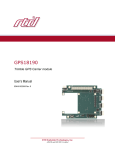
SATA34106
SATA Drive Carrier
User’s Manual
BDM-610020085 Revision B
®
www.rtd.com
ISO9001 and AS9100 Certified
“Accessing the Analog World”®
SATA Drive Carrier User’s Manual
RTD Document Number: BDM-610020085 Revision B
Copyright © 2012 RTD Embedded Technologies, Inc. All rights reserved.
Trademarks
Advanced Digital I/O, aDIO, a2DIO, Autonomous SmartCal, cpuModule, dspFramework, dspModule, IDAN, HiDAN,
HiDANplus, “MIL Value for COTS prices”, multiPort, and PC/104EZ are trademarks, and “Accessing the Analog World”,
dataModule, RTD, and the RTD logo are registered trademarks of RTD Embedded Technologies, Inc. PS/2, PC/XT,
PC/AT, and IBM are trademarks of International Business Machines Inc. MS-DOS, Windows, Windows 95, Windows 98,
and Windows NT are trademarks of Microsoft Corp. PC/104 is a registered trademark of PC/104 Consortium. All other
trademarks appearing in this document are the property of their respective owners.
Contents and specifications within this manual are subject to change without notice.
Revision History
2
Revision
Date
Reason for Change
A
9/30/10
Initial Release
B
10/4/12
Changed bus name to PCIe/104 Type 2
SATA34106 SATA Drive Carrier
BDM-610020085
Rev B
SATA34106
SATA Drive Carrier
®
www.rtd.com
ISO9001 and AS9100 Certified
“Accessing the Analog World”®
Contact Information
RTD Embedded Technologies, Inc.
103 Innovation Blvd.
State College, PA 16803-0906
USA
Phone:
Fax:
+1-814-234-8087
+1-814-234-5218
E-mail:
[email protected]
[email protected]
Internet:
http://www.rtd.com
4
SATA34106 SATA Drive Carrier
BDM-610020085
Rev B
Table of Contents
Chapter 1
Introduction
SATA34106 SATA Drive Carriers . . . . . . . . . . . . . . . . . . . . . . . . . . . . . . . . . . . . . . . . . . . . . . . . . . . . . . . . . . . . . . . . . . . . . . .
8
Ordering Information . . . . . . . . . . . . . . . . . . . . . . . . . . . . . . . . . . . . . . . . . . . . . . . . . . . . . . . . . . . . . . . . . . . . . . . . . . . . . . . . .
9
Stand Alone Models . . . . . . . . . . . . . . . . . . . . . . . . . . . . . . . . . . . . . . . . . . . . . . . . . . . . . . . . . . . . . . . . . . . . . . . . . . . . . . . . . . . . . . . . .
IDAN Models . . . . . . . . . . . . . . . . . . . . . . . . . . . . . . . . . . . . . . . . . . . . . . . . . . . . . . . . . . . . . . . . . . . . . . . . . . . . . . . . . . . . . . . . . . . . . . . .
9
9
Features . . . . . . . . . . . . . . . . . . . . . . . . . . . . . . . . . . . . . . . . . . . . . . . . . . . . . . . . . . . . . . . . . . . . . . . . . . . . . . . . . . . . . . . . . . . . . . .
10
Specifications. . . . . . . . . . . . . . . . . . . . . . . . . . . . . . . . . . . . . . . . . . . . . . . . . . . . . . . . . . . . . . . . . . . . . . . . . . . . . . . . . . . . . . . . . .
10
Connectors . . . . . . . . . . . . . . . . . . . . . . . . . . . . . . . . . . . . . . . . . . . . . . . . . . . . . . . . . . . . . . . . . . . . . . . . . . . . . . . . . . . . . . . . . . . . . . . . . .
Operating Temperature Range . . . . . . . . . . . . . . . . . . . . . . . . . . . . . . . . . . . . . . . . . . . . . . . . . . . . . . . . . . . . . . . . . . . . . . . . . . . . . . .
10
10
For More Information . . . . . . . . . . . . . . . . . . . . . . . . . . . . . . . . . . . . . . . . . . . . . . . . . . . . . . . . . . . . . . . . . . . . . . . . . . . . . . . . .
11
Chapter 2
Connecting the SATA Drive Carrier
Installation Considerations. . . . . . . . . . . . . . . . . . . . . . . . . . . . . . . . . . . . . . . . . . . . . . . . . . . . . . . . . . . . . . . . . . . . . . . . . . . .
14
Proper Grounding Techniques. . . . . . . . . . . . . . . . . . . . . . . . . . . . . . . . . . . . . . . . . . . . . . . . . . . . . . . . . . . . . . . . . . . . . . . . .
14
SATA Drive Carrier Installation. . . . . . . . . . . . . . . . . . . . . . . . . . . . . . . . . . . . . . . . . . . . . . . . . . . . . . . . . . . . . . . . . . . . . . . .
14
SATA34106 Connector Locations. . . . . . . . . . . . . . . . . . . . . . . . . . . . . . . . . . . . . . . . . . . . . . . . . . . . . . . . . . . . . . . . . . . . . .
15
PCIe/104 Type 2 Bus (CN1 & CN2) . . . . . . . . . . . . . . . . . . . . . . . . . . . . . . . . . . . . . . . . . . . . . . . . . . . . . . . . . . . . . . . . . . . .
16
PCIe/104 Type 2 Compatibility . . . . . . . . . . . . . . . . . . . . . . . . . . . . . . . . . . . . . . . . . . . . . . . . . . . . . . . . . . . . . . . . . . . . . . . . . . . . . . .
Pin Connections . . . . . . . . . . . . . . . . . . . . . . . . . . . . . . . . . . . . . . . . . . . . . . . . . . . . . . . . . . . . . . . . . . . . . . . . . . . . . . . . . . . . . . . . . . . . .
16
16
2.5” SATA Drive Connector (CN3) . . . . . . . . . . . . . . . . . . . . . . . . . . . . . . . . . . . . . . . . . . . . . . . . . . . . . . . . . . . . . . . . . . . . .
20
SATA Link Shifting . . . . . . . . . . . . . . . . . . . . . . . . . . . . . . . . . . . . . . . . . . . . . . . . . . . . . . . . . . . . . . . . . . . . . . . . . . . . . . . . . . . . . . . . . . .
20
Appendix 1
IDAN™ Dimensions and Pinout
IDAN-SATA34106. . . . . . . . . . . . . . . . . . . . . . . . . . . . . . . . . . . . . . . . . . . . . . . . . . . . . . . . . . . . . . . . . . . . . . . . . . . . . . . . . . . . . .
Appendix 2
22
Limited Warranty
BDM-610020085 Rev B
5
6
SATA34106 SATA Drive Carrier
BDM-610020085
Rev B
Chapter 1
Introduction
This manual provides comprehensive hardware information on the SATA34106.
This manual is organized as follows:
Chapter 1
Introduction
introduces product variations and their main features and specifications
Chapter 2
Connecting the SATA Drive Carrier
provides information on installing the SATA drive carrier in a system
Appendix 1
IDAN™ Dimensions and Pinout
provides connector pinouts and locations for variations of SATA drive carriers installed in an
RTD Intelligent Data Acquisition Node (IDAN™) frame
Appendix 2
Limited Warranty
BDM-610020085 Rev B
Chapter 1: Introduction
7
SATA34106 SATA Drive Carriers
The SATA34106 SATA drive carrier modules provide a mechanism to utilize the SATA links on the PCIe/104 Type 2 bus
connector on select RTD’s PCI Express cpuModules. The onboard drive utilizes the first SATA link on the connector, while
the other SATA link is lane-shifted up the stack, to permit stacking multiple SATA drive carrier modules within one system.
The SATA34106 drive carrier provides power to the SATA drive, sourcing the power from the cpuModule’s onboard
connector, and thus eliminates the need for external out-of-stack cabling.
This manual provides instructions on how to install a 2.5” SATA drive in the SATA34106, and how to install the SATA34106
module into a PCI/104-Express or PCIe/104 system. It will help you get the SATA drive carrier module up and running
quickly, and will also provide enough detail about the board and its functions so you can get maximum use of its features in
the most demanding applications.
2.5” SATA Drive
Connector (CN3)
PCIe/104 Type 2
Bus Connector
(CN1 - Top,
CN2 - Bottom)
Figure 1 SATA34106 SATA Drive Carrier (top view)
8
SATA34106 SATA Drive Carrier
BDM-610020085
Rev B
Ordering Information
There are several versions of the SATA drive carrier module, some of which are designed for specific usage in an IDAN frame.
Stand Alone Models
The base design variant, intended for use without an RTD system enclosure, may be ordered with the following model
number:
–
SATA34106:
2.5” SATA drive carrier for use with a standalone cpuModule
IDAN Models
The SATA drive carrier can be purchased as part of an Intelligent Data Acquisition Node (IDAN™) building block, which
consists of the SATA Drive Carrier module, and a milled aluminum IDAN frame. The IDAN building block can be used in just
about any combination with other IDAN building blocks to create a simple but rugged PCI/104-Express or PCIe/104 stack.
(for more information refer to Appendix 1).
Design variants of the SATA drive carrier module installed in an IDAN frame can be ordered with the following model
numbers:
–
IDAN-SATA34106HRS: 2.5” SATA drive carrier for use in an IDAN system
–
IDAN-RSATA-SYS104:
2.5” SATA drive carrier with removable-drive access for use in an IDAN system
The SATA drive carrier can also be purchased as part of a custom-built RTD HiDAN™ or HiDANplus High Reliability
Intelligent Data Acquisition Node. Contact RTD for more information on its high reliability PC/PCI-104, PCI/104-Express,
and PCIe/104 systems.
Each SATA drive carrier module package contains the following items:
•
•
SATA34106 SATA drive carrier module
Companion CD containing documentation
BDM-610020085 Rev B
Ordering Information
9
Features
Some of the key features of the SATA drive carrier include:
•
Adds one 2.5” SATA (Serial ATA) drive to a system using the PCIe/104 Type 2 bus interface on select RTD
cpuModules
–
Stack up to 2x SATA drive carrier modules in one system
•
•
•
Benefits of SATA over PATA (Parallel ATA)
–
Transfer rates up to 3.0 Gbits per second is faster and more efficient than PATA
–
Dedicated SATA links for each drive in the system eliminate master/slave addressing jumpers
–
Backwards compatibility with PATA permits use of Legacy Mode
Stackable PCIe/104 Type 2 Expansion Bus
–
•
Useful for RAID configurations
Permits system expandability by passing unused SATA links, PCI-Express links, and USB ports from the
cpuModule to the next expansion module in the system
Physical and environmental characteristics
–
Supports 2.5” SATA rotating or flash drives
–
–40 to +85°C operating temperature1
–
RTD IDAN™ compatible (see Appendix 1, IDAN™ Dimensions and Pinout)
Specifications
Connectors
•
•
PCIe/104 Type 2 Bus
156-pin Surface Mount (Top & Bottom)
SATA Connector
2.5” SATA drive
Operating Temperature Range
Standard
–40 to +85°C
1.
Operating temperature range may be limited by the rating of the SATA drive installed in the SATA drive carrier module
10
SATA34106 SATA Drive Carrier
BDM-610020085
Rev B
For More Information
Contact RTD if you need further assistance.
RTD Embedded Technologies, Inc.
103 Innovation Blvd.
State College, PA 16803-0906
USA
Phone:
Fax:
+1-814-234-8087
+1-814-234-5218
E-mail:
[email protected]
[email protected]
Internet:
http://www.rtd.com
BDM-610020085 Rev B
For More Information
11
12
SATA34106 SATA Drive Carrier
BDM-610020085
Rev B
Chapter 2
Connecting the SATA Drive Carrier
The SATA34106 SATA drive carrier module interfaces easily to PCI/104-Express and PCIe/104 systems via the PCIe/104 Type
2 bus connector. This chapter provides general installation guidelines for the SATA34106 as well as information on all
connectors.
Installation Considerations—page 14
Proper Grounding Techniques—page 14
SATA Drive Carrier Installation—page 14
SATA34106 Connector Locations—page 15
PCIe/104 Type 2 Bus (CN1 & CN2)—page 16
2.5” SATA Drive Connector (CN3)—page 20
BDM-610020085 Rev B
Chapter 2: Connecting the SATA Drive Carrier
13
Installation Considerations
The SATA34106 is a module with an PCIe/104 Type 2 bus. Therefore, the SATA34106 should only be installed on a
cpuModule which has an PCIe/104 Type 2 bus connector.
CAUTION The PCIe/104 Type 2 connector is the same physical connector as the PCIe/104 Type 1
connector, but has a different pinout. Though it is physically possible to connect the SATA34106
directly to a PCIe/104 Type 1 bus, doing so could harm the module and other boards in the system.
Proper Grounding Techniques
Before removing the SATA34106 from its static bag, proper grounding techniques must be used to prevent electrostatic
discharge (ESD) damage to the module. Common grounding procedures include an anti-static mat on a workbench, which
may connect to an anti-static wrist strap (also known as an ESD wrist strap) on the wrist of the technician or engineer.
SATA Drive Carrier Installation
1.
Turn off power to your PCI/104-Express or PCIe/104 system and unplug the cord.
2.
Ground yourself with an anti-static strap.
3.
Line up the pins of the SATA34106’s bottom side connector with the PCIe/104 Type 2 bus of the stack and gently
press the module onto the stack.
CAUTION The SATA34106 should slide into the connectors on the matching PCI/104-Express or
PCIe/104 system easily. Do not force the connection. Doing so might damage pins on the connectors.
14
4.
If any modules are to be installed on the PCIe/104 Type 2 bus above the SATA34106, install them.
5.
Attach any necessary cables to the stack.
6.
Reconnect the power cord and apply power to the stack.
7.
Boot the system and verify that all of the hardware is working properly.
SATA34106 SATA Drive Carrier
BDM-610020085
Rev B
SATA34106 Connector Locations
Figure 2 shows the connectors of the SATA driver carrier module.
2.5” SATA Drive
Connector (CN3)
PCIe/104 Type 2
Bus Connector
(CN1 - Top,
CN2 - Bottom)
Figure 2
SATA34106 Connector Locations
Note Pin 1 of the PCIe/104 Type 2 bus connectors is indicated by a silk screen border at the corner of
each connector on the top and bottom of the board. Pin 1 of each connector matches when stacking with
other PCIe/104 Type 2 modules.
Table 1
SATA34106 Connectors
Connector
Function
Size
CN1
PCIe/104 Type 2 Bus (top)
156-pin
CN2
PCIe/104 Type 2 Bus (bottom)
156-pin
CN3
2.5” SATA Drive Connector
7-pin (data segment),
14-pin (power segment)
BDM-610020085 Rev B
SATA34106 Connector Locations
15
PCIe/104 Type 2 Bus (CN1 & CN2)
PCIe/104 Type 2 Compatibility
The PCIe/104 Type 2 bus is compatible with any PCI/104-Express or PCIe/104 peripheral module that does not use the x16
Link. This includes any card that uses the PCIe x1 links, USB, or a power supply.
Pin Connections
The signals on the first bank match definitions found in the PCI/104-Express & PCIe/104 Specification Version 1.1 from the
PC/104 Embedded Consortium. The signals on the second and third bank are used for SATA hard drive carrier expansion.
Table 2 lists the pinout of the PCIe/104 Type 2 bus connector.
Connector CN1 on the bottom side of the SATA34106 is the source for the signals of the cpuModule’s PCIe/104 Type 2 bus.
The only connections on the top-side PCIe/104 Type 2 bus connector (CN1) that are not directly passed through from the
bottom-side connector (CN2) are the SATA links. Other unused features on the bus that are provided by the cpuModule
are passed through the SATA34106’s bus connector to the next peripheral module in the stack.
For details on how the SATA links are utilized and passed through the SATA34106, refer to SATA Link Shifting—page 20.
Note Pin 1 of the PCIe/104 Type 2 bus connectors is indicated by a silk screen border at the corner of
each connector on the top and bottom of the board.
16
SATA34106 SATA Drive Carrier
BDM-610020085
Rev B
Table 2
BDM-610020085 Rev B
PCIe/104 Type 2 Bus Signal Assignments1
Signal
Signal
Pin
1
Pass-through
Pass-through
2
3
+3.3V
+3.3V
4
5
Pass-through
Pass-through
6
7
Pass-through
Pass-through
8
9
GND
GND
10
11
Pass-through
Pass-through
12
13
Pass-through
Pass-through
14
15
GND
GND
16
17
Pass-through
Pass-through
18
19
Pass-through
Pass-through
20
21
GND
GND
22
23
Pass-through
Pass-through
24
25
Pass-through
Pass-through
26
27
GND
GND
28
29
Pass-through
Pass-through
30
31
Pass-through
Pass-through
32
33
GND
GND
34
35
Pass-through
Pass-through
36
37
Pass-through
Pass-through
38
39
Pass-through
Pass-through
40
41
Pass-through
Pass-through
42
43
Pass-through
Pass-through
44
45
CPU_DIR
Pass-through
46
47
Pass-through
Pass-through
48
49
Pass-through
Pass-through
50
51
Pass-through
Pass-through
52
+5 Volts
Pin
PCIe/104 Type 2 Bus (CN1 & CN2)
17
Table 2
Signal
Signal
Pin
53
Reserved
Pass-through
54
55
GND
GND
56
57
Pass-through
Pass-through
58
59
Pass-through
Pass-through
60
61
GND
GND
62
63
Pass-through
Pass-through
64
65
Pass-through
Pass-through
66
67
GND
GND
68
69
Pass-through
Pass-through
70
71
Pass-through
Pass-through
72
73
GND
GND
74
75
Pass-through
Pass-through
76
77
Pass-through
Pass-through
78
79
GND
GND
80
+5 Volts
Pin
SATA_1Tp
2
83
SATA_1Tn
2
85
GND
GND
86
87
Pass-through
Pass-through
88
89
Pass-through
Pass-through
90
91
GND
GND
92
93
Pass-through
Pass-through
94
95
Pass-through
Pass-through
96
97
GND
GND
98
81
18
PCIe/104 Type 2 Bus Signal Assignments1
2
SATA_0Tp
2
82
SATA_0Tn
2
84
2
99
SATA_DET#1
SATA_DET#0
101
SATA_PWREN#12
SATA_PWREN#02
102
103
GND
GND
104
SATA34106 SATA Drive Carrier
100
BDM-610020085
Rev B
Table 2
PCIe/104 Type 2 Bus Signal Assignments1
Signal
Signal
Pin
105
Pass-through
Pass-through
106
107
GND
GND
108
109
Pass-through
Pass-through
110
111
Pass-through
Pass-through
112
113
GND
GND
114
115
Pass-through
Pass-through
116
117
Pass-through
Pass-through
118
119
GND
GND
120
121
Pass-through
Pass-through
122
123
Pass-through
Pass-through
124
125
GND
GND
126
127
Pass-through
Pass-through
128
129
Pass-through
Pass-through
130
131
GND
GND
132
+12 Volts
Pin
SATA_1Rp
2
135
SATA_1Rn
2
137
GND
GND
138
139
Pass-through
Pass-through
140
141
Pass-through
Pass-through
142
143
GND
GND
144
145
Pass-through
Pass-through
146
147
Pass-through
Pass-through
148
149
GND
GND
150
151
Pass-through
Pass-through
152
153
Pass-through
Pass-through
154
155
GND
GND
156
133
SATA_0Rp
2
134
SATA_0Rn
2
136
1.Signals marked with (#) are active low.
2.For a description of SATA lane usage on the SATA34106, refer to SATA
Link Shifting—page 20.
BDM-610020085 Rev B
PCIe/104 Type 2 Bus (CN1 & CN2)
19
2.5” SATA Drive Connector (CN3)
The 2.5” SATA drive connector on the SATA34106 provides a convenient interface to the first SATA link on the PCIe/104
Type 2 bus on RTD’s PCI Express cpuModules.
SATA Link Shifting
The SATA34106’s 2.5” SATA Drive Connector (CN3) utilizes the first SATA link on the PCIe/104 Type 2 bus. As a result, the
unused SATA link on the bus is shifted from the bottom-side PCIe/104 Type 2 connector (CN2) to the top-side (CN1).
Shifting the remaining link allows a second SATA34106 (or other SATA drive carrier) to be installed upwards in the stack.
Figure 3 shows a block diagram of the SATA drive carrier module and how it interfaces to the cpuModule.
Figure 3
20
SATA34106 SATA Drive Carrier
SATA34106 - Block Diagram
BDM-610020085
Rev B
Appendix 1
IDAN™ Dimensions and Pinout
SATA Drive Carrier modules, like all other RTD PC/PCI-104, PCI/104-Express, and PCIe/104 modules, can be packaged in
Intelligent Data Acquisition Node (IDAN) frames, which are milled aluminum frames with integrated heat sinks and heat
pipes for fanless operation. RTD modules installed in IDAN frames are called building blocks. IDAN building blocks maintain
the simple but rugged PC/104 stacking concept. Each RTD module is mounted in its own IDAN frame and all I/O
connections are brought to the walls of each frame using standard PC connectors. No connections are made from module
to module internal to the system other than through the PC/104 and PC/104-Plus bus, enabling quick interchangeability and
system expansion without hours of rewiring and board redesign.
The SATA34106 SATA Drive Carrier can also be purchased as part of a custom-built RTD HiDAN™ or HiDANplus™ High
Reliability Intelligent Data Acquisition Node. This appendix provides the dimensions and pinouts of the SATA34106 installed
in an IDAN frame. Contact RTD for more information on high reliability IDAN, HiDAN, and HiDANplus PC/PCI-104,
PCI/104-Express, and PCIe/104 systems.
IDAN—Adhering to the PC/104 stacking concept,
IDAN allows you to build a customized system
with any combination of RTD modules.
IDAN Heat Pipes—Advanced heat pipe technology
maximizes heat transfer to heat sink fins.
HiDANplus—Integrating the modularity of
IDAN with the ruggedization of HiDAN,
HiDANplus enables connectors on all system
frames, with signals running between frames
through a dedicated stack-through raceway.
BDM-610020085 Rev B
Appendix 1: IDAN™ Dimensions and Pinout
21
IDAN-SATA34106
The IDAN-SATA34106 is a SATA34106 SATA Drive Carrier packaged in an IDAN frame which permits easy removal of data
from a PCI/104-Express or PCIe/104 system.
Note Photographs not to scale.
Figure 4
Figure 5
22
SATA34106 SATA Drive Carrier
IDAN-SATA34106
IDAN-SATA34106, Example Configurations
BDM-610020085
Rev B
Appendix 2
Limited Warranty
RTD Embedded Technologies, Inc. warrants the hardware and software products it manufactures and produces to be free
from defects in materials and workmanship for one year following the date of shipment from RTD Embedded Technologies,
Inc. This warranty is limited to the original purchaser of product and is not transferable.
During the one year warranty period, RTD Embedded Technologies will repair or replace, at its option, any defective
products or parts at no additional charge, provided that the product is returned, shipping prepaid, to RTD Embedded
Technologies. All replaced parts and products become the property of RTD Embedded Technologies. Before returning any
product for repair, customers are required to contact the factory for a Return Material Authorization number.
This limited warranty does not extend to any products which have been damaged as a result of accident, misuse, abuse (such
as: use of incorrect input voltages, improper or insufficient ventilation, failure to follow the operating instructions that are
provided by RTD Embedded Technologies, "acts of god" or other contingencies beyond the control of RTD Embedded
Technologies), or as a result of service or modification by anyone other than RTD Embedded Technologies. Except as
expressly set forth above, no other warranties are expressed or implied, including, but not limited to, any implied warranties
of merchantability and fitness for a particular purpose, and RTD Embedded Technologies expressly disclaims all warranties
not stated herein. All implied warranties, including implied warranties for merchantability and fitness for a particular
purpose, are limited to the duration of this warranty. In the event the product is not free from defects as warranted above,
the purchaser's sole remedy shall be repair or replacement as provided above. Under no circumstances will RTD Embedded
Technologies be liable to the purchaser or any user for any damages, including any incidental or consequential damages,
expenses, lost profits, lost savings, or other damages arising out of the use or inability to use the product.
Some states do not allow the exclusion or limitation of incidental or consequential damages for consumer products, and
some states do not allow limitations on how long an implied warranty lasts, so the above limitations or exclusions may not
apply to you.
This warranty gives you specific legal rights, and you may also have other rights which vary from state to state.
RTD Embedded Technologies, Inc.
103 Innovation Blvd.
State College PA 16803-0906
USA
Website: www.rtd.com
BDM-610020085 Rev B
Appendix 2: Limited Warranty
23
24
SATA34106 SATA Drive Carrier
BDM-610020085
Rev B