1
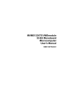
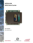
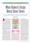
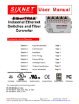
C H A P T E R
4
Storage/Control I/O Module
The Storage/Control I/O Module performs two functions: to connect outside interfaces to the system
controller and to house the hard disk drive. It plugs into the back of the VCO/4K system and provides
the I/O interfaces for system peripheral devices and host communication links using four serial ports,
one Ethernet port, one printer port and one SCSI connector. Figure 4-1 shows the front panel of the
Storage/Control I/O Module.
Physical interfaces to host computers and peripheral devices are provided on the front panel of the
Storage/Control I/O Module. Two serial ports are available for SIO host links, and another two are
dedicated to supporting the local system administration console and a remote maintenance modem. An
Ethernet Transceiver interface and parallel printer connector are also located on the Storage/Control I/O
Module.
Specifications
Part Number
Contact your Cisco Systems sales representative
Interfaces
Four EIA/TIA-232 serial ports (master console, remote maintenance modem,
and two SIO host links)
One Ethernet transceiver interface
One Centronics-type parallel interface (system printer)
One SCSI connector (reserved for future use)
Power Requirements:
Hard Disk Drive
Ethernet
EIA/TIA-232
Maximum
Typical
+5 VDC
0.4A
0.33A
+12 VDC
1.0A
0.17A
+5 VDC
0.5A
0.5A
+12 VDC
0A
0A
+5 VDC
0A
0A
+12 VDC
0.1A
0.05A
Cisco VCO/4K Mechanical Assemblies
78-10334-03
4-1
Chapter 4
Storage/Control I/O Module
Description
Total Current
Total Power
+5 VDC
0.9A
0.85A
+12 VDC
1.1A
.22A
+.5 VDC
7.7 Watts
+12 VDC
6.89 Watts
Operating Temperature 10 to 40°C (50 to 104°F)
Relative Humidity
20 to 80% (noncondensing)
Physical Dimensions
Height:
14.4 inch (36.6 cm)
Depth:
5.6 inch (14.2 cm)
Width:
1.6 inch (4.1 cm)
Description
The Storage I/O Module is two card slots wide and slides into the back of the VCO system where it plugs
into the control midplane. All outside connections are mounted on the faceplate of the module. All
internal connectors are mounted on the board itself for easy access to system internals (for example,
SCSI and Ethernet).
The VCO/4K system hard drive is mounted on the upper portion of the I/O Module. The board is built
to accommodate a 3.5-inch hard drive. Physical mounting points are provided for the hard drive as well
as a 50-pin SCSI interface to the system controller. There is also a provision for an external SCSI
connection on the front panel. The SCSI connection is reserved for future use.
Front Panel Indicators and Ports Assignments
Figure 4-1 shows the front panel of the Storage/Control I/O Module.
Cisco VCO/4K Mechanical Assemblies
4-2
78-10334-03
Chapter 4
Storage/Control I/O Module
Description
Figure 4-1
Storage/Control I/O Module Front Panel
ST /CTRL - I/O
TT RT
Y0 2
1
3
50165
PO
RT
PO
4
RT
PO
C PO
O R
N T
SO 1
LE
PR
IN
TE
R
ET
H
ER
N
ET
IN
TE SC
R SI
FA
C
E
SCSI TRM PWR
ENET PWR
Power is supplied to the Storage/Control I/O Module via the midplane from the Combined Controller
card. The hard drive LED signal is brought to the system controller board via the midplane and brought
out to the front panel to show hard drive activity. It is located on the Combined Controller in the front
of the VCO (see Figure 4-3).
SCSI terminations are provided as an option to be populated on the Storage/Control I/O Module
depending on the system configuration. They are currently not being used.
Cisco VCO/4K Mechanical Assemblies
78-10334-03
4-3
Chapter 4
Storage/Control I/O Module
Description
The connectors mounted on the front pane are:
:
4 serial ports
DB-25
SCSI port
50-pin mini-SCSI connector
Ethernet
DB-15
Printer
36-pin Centronics
The connectors mounted on the board are:
SCSI
DIN 64
MODEM
20-pin IDC connector
MODEM power
5-pin header
The LEDs mounted on the board are:
ENET
If illuminated, shows that power is available to the
Ethernet
SCSI
If illuminated, shows that there is SCSI termination
power
Hard Disk Drive
The hard disk drive is a SCSI-compatible drive that is used as the system controller’s main data storage
facility. The hard disk drive requires +5 volts and +12 volts DC to operate. The hard disk drive is shown
in Figure 4-2. The Storage/Control I/O Module supports the hard disk drive LED. The LED is located
on the Combined Controller and is visible from the front of the system (see Figure 4-3).
Cisco VCO/4K Mechanical Assemblies
4-4
78-10334-03
Chapter 4
Storage/Control I/O Module
Description
Figure 4-2
Location of the Hard Disk Drive on the Storage/Control I/O Module
50166
Hard disk drive
Cisco VCO/4K Mechanical Assemblies
78-10334-03
4-5
Chapter 4
Storage/Control I/O Module
Description
Figure 4-3
Location of Hard Disk Drive LED on the Combined Controller
C I S CO S Y S T E M S
B
A
RESET
ACO
AUTO
A
A
B
M
AJ
O
M R
IN
O
AU R
X
1
AU
X
2
R
ACO
B
SELECT
AAC
ALARMS
ACTIVE
NG
INSERT ONLY CARDS DESIGNATED BELOW
For Non-Redundant configuration use slots 1,3-4
For Redundant configuration use slots 1,2, 3-4, 5-6
NBC
NBC
COMBINED
COMBINED
CONTROLLER
CONTROLLER
CPU
FAIL
STATUS
CONNECT ESD
WRIST STRAP HERE
CPU
FAIL
STATUS
RUN
RUN
SCON
SCON
RMT RST
RMT RST
ABORT
ABORT
RESET
RESET
Hard disk
drive LEDs
MOTOROLA
RING
GEN.
POWER
RING
GEN.
50167
POWER
MOTOROLA
Midplane Connectors
The Storage/Control I/O Module plugs into the midplane through standard DIN 41612 triple-row, 96-pin
male connectors. Figure 4-4 shows the control midplane connectors.
Cisco VCO/4K Mechanical Assemblies
4-6
78-10334-03
Chapter 4
Storage/Control I/O Module
Description
Figure 4-4
Control Midplane
A-side connector for the
Storage/Control I/O module
50168
B-side connector for the
Storage/Control I/O module
Serial Ports 1 and 2
Serial Port 1/Console and Serial Port 2/TTY01 are dedicated ports for connecting the system master
console and remote maintenance modem, respectively. These standard female DB-25 ports connect to
the console and modem via EIA/TIA-232 cables. Table 4-1 shows the pin and signal assignments for
these ports. For additional information on connecting peripheral equipment, refer to the Cisco VCO/4K
Hardware Installation Guide.
Table 4-1
Serial Ports 1 and 2 Pin and Signal Assignments1
Pin
Signal Name
Description/Direction
2
TxD
Transmit Data (terminal to modem)
3
RxD
Receive Data (modem to terminal)
4
RTS
Request to Send (terminal to modem)
5
CTS
Clear to Send (modem to terminal)
6
DSR
Data Set Ready (modem to terminal)
7
GND
Chassis Ground
8
DCD
Data Carrier Detect (modem to terminal)
20
DTR
Data Terminal Ready (terminal to modem)
1. All pins not identified are no-connection.
Cisco VCO/4K Mechanical Assemblies
78-10334-03
4-7
Chapter 4
Storage/Control I/O Module
Description
Master console and remote maintenance modem operating parameters (Baud Rate, Stop Bits, Bits per
Character and Parity) are defined in the system database via the Peripheral Configuration screen. Wiring
for serial port connection to the Master Console is shown in Figure 4-5. Wiring for the remote
maintenance modem connection is shown in Figure 4-6. Refer to the Cisco VCO/4K System
Administrator’s Guide for more information.
I/O Module to Master Console—Cable Wiring Diagram
Serial Port 1/Console
(DB-25P)
Male
VT220/320 Console
(DB-25S)
TxD
Pin 2
RxD
Pin 3
Pin 7
You can use a 25-conductor, straight-through cable to connect a master console to the
Storage/Control I/O Module. However, only the conductors shown in Figure 4-5 are used.
I/O Module to Remote Maintenance Modem—Cable Wiring Diagram
Remote Maintenance
Modem
(DB-25P)
Serial Port 2/TTY01
(DB-25P)
Male
Pin 2
Male
(7-conductor, Straight-thru)
TxD
Pin 2
Pin 3
RxD
Pin 5
Pin 6
DSR
CTS
GND
Pin 7
Pin 20
DTR
Pin 5
Pin 6
Pin 7
DCD
Pin 8
Pin 3
Pin 8
Pin 20
50170
Figure 4-6
Note
Pin 2
Pin 3
GND
Pin 7
Note
Female
(3-Conductor, Straight-Thru)
50169
Figure 4-5
You must use a 9-pin connector (available from Cisco Systems). A 25-pin connector can be
used after the switch box.
Cisco VCO/4K Mechanical Assemblies
4-8
78-10334-03
Chapter 4
Storage/Control I/O Module
Description
Serial Ports 3 and 4
Serial Ports 3 and 4 are available for Serial I/O (SIO) links between the system and a host computer.
These standard female DB-25 ports carry Asynchronous Data Link Control (ADLC) protocol signals
between the host and the system over EIA/TIA-232 cables. Pin and signal assignments for port 3 is the
same as Serial Ports 1 and 2. Refer to Table 4-2 for port 4 pin and signal assignments.
Wiring conventions for physically connecting a host computer to a SIO port are provided in the Cisco
VCO/4K Hardware Installation Guide. Jumpers on the Storage/Control I/O Module allow Serial Ports 3
and 4 to be configured as modem (DCE) terminations for connection to a terminal or configured as
terminal (DTE) terminations for connection to a modem. Refer to the “Serial Ports 1 Through 4 and
Jumper Settings” section on page 4-11 for more information on jumper configurations.
Data communication parameters for each host link must be defined in the system database using the Host
Configuration screen following system power-on. Refer to the Cisco VCO/4K System Administrator’s
Guide for instructions on defining host links.
Table 4-2
Serial Ports 3 and 4 Pin and Signal Assignments1
Pin
Signal Name
Description/Direction
2
TxD
Transmit Data (terminal to modem)
3
RxD
Receive Data (modem to terminal)
4
RTS
Request to Send (terminal to modem)
5
CTS
Clear to Send (modem to terminal)
6
DSR
Data Set Ready (modem to terminal)
7
GND
Chassis Ground
8
DCD
Data Carrier Detect (modem to terminal)
15
RTxC
Tx Clock to output data (terminal to modem)
17
RRxC
Rx Clock to input data (terminal to modem)
20
DTR
Data Terminal Ready (terminal to modem)
24
TTxC
Tx Clock to output data (terminal to modem)
1. All pins not identified are no-connection.
Ethernet Interface
The CPU employs a Local Area Network Controller for Ethernet (LANCE) to implement an Ethernet
transceiver interface. The balanced transceiver signal lines from the CPU are coupled to an onboard
transformer to signal lines that go through the SWI, Outer B/P and control midplane cards, and terminate
on the industry-standard DB-15 connector on the Storage/Control I/O Module faceplate. Pin and signal
assignments for this DB-15 port are listed in Table 4-3.
Cisco VCO/4K Mechanical Assemblies
78-10334-03
4-9
Chapter 4
Storage/Control I/O Module
Description
Table 4-3
Ethernet Port Pin and Signal Assignments
Pin
Signal
Signal Name
2
C+
Collision + (Input)
3
T+
Transmit + (Output)
5
R+
Receive + (Input)
6
GND
Ground
9
C–
Collision – (Input)
10
T–
Transmit – (Output)
12
R–
Receive – (Input)
To implement Ethernet links, you must purchase the optional Ethernet Communications Package
available from Cisco Systems. This package contains supporting software and the Cisco VCO/4K
Ethernet Guide which covers the cabling requirements and implementation strategies. You must provide
cables, transceivers and other components to establish Ethernet links.
Printer Interface
The printer interface on the Storage/Control I/O Module front panel supports parallel system printers
through a 36-pin Centronics-type connector. Figure 4-7 shows the cable wiring diagrams for connecting
the Storage/Control I/O Module parallel port to the system printer.
The End of Line (EOL) terminator for the system printer must be defined in the system
database via the Peripheral Configuration screen prior to use (refer to the Cisco VCO/4K
System Administrator’s Guide for more information).
Figure 4-7
I/O Module to System Printer—Cable Wiring Diagram
Printer
(36-pin Centronics)
Male
Parallel Printer
(36-pin)
(29-conductor, Straight-thru)
Male
Pin 1
Pin 1
Pin 13
Pin 13
Pin 16
GND
Pin 16
Pin 19
Pin 19
Pin 32
Pin 32
50171
Note
Cisco VCO/4K Mechanical Assemblies
4-10
78-10334-03
Chapter 4
Storage/Control I/O Module
Hardware Configuration
Note
You can use a 36-conductor, straight-through parallel cable to connect a printer to the
system controller. However, only the conductors shown in Figure 4-7are used. For more
information on the parallel 36-pin Centronics cable available from Cisco Systems, refer to
the Cisco VCO/4K Hardware Planning Guide.
SCSI Interface
The SCSI mass storage bus interface on the Storage/Control I/O Module is not used in system operation.
Hardware Configuration
This section outlines hardware configuration options.
SCSI Termination Configuration
The SCSI Interface connector is reserved for future use.
Serial Port Configuration
Serial Ports 1 Through 4 and Jumper Settings
Serial ports 1 through 4 on the Storage/Control I/O Module can be configured as modem (DCE)
terminations for connection to a terminal or configured as terminal (DTE) terminations for connection
to a modem. (Refer to the “Serial Ports 1 Through 4” section on page 4-12 for more information.)
Jumpers are positioned in J1 for Serial Port 1 (master console), JP17 for Serial Port 2 (remote
maintenance modem, and JP13 and JP18 for Serial Ports 3 and 4 (SIO host links), respectively.
For Serial Ports 1 and 2, these jumper settings assume that straight-through EIA (DCE to DTE) cables
are used to connect the system to the master console and remote maintenance modem. If the jumpers are
moved to position JP11 (for the master console) and JP16 (for the remote modem), crossover cables can
be used.
Note
Straight-through cables directly link the connector pinouts from end-to-end. In crossover
cables, Pins 2 and 3 are crosswired; Pin 2 at one end is wired to Pin 3 at the opposite end,
and vice versa.
Jumper settings for Serial Ports 3 and 4 (SIO host links) are determined by two factors: the type of cable
employed (straight-through or crossover) and the host termination at the end of the cable (terminal or
modem).
The default jumper settings for Serial Ports 3 and 4 configure the CPU as a DTE termination. This
configuration supports the following arrangements:
•
Straight-through cables connecting the system to a modem (DTE to DCE)
•
Crossover (null modem) cables connecting the system to a terminal (DTE to DTE)
Cisco VCO/4K Mechanical Assemblies
78-10334-03
4-11
Chapter 4
Storage/Control I/O Module
Hardware Configuration
You can position the jumpers in locations JP13 and JP18 (under the “To Terminal” etching) to configure
the CPU as a DCE termination. Moving the jumpers to these locations supports the following SIO
connections:
•
Straight-through cables connecting the system to a host terminal (DCE to DTE)
•
Crossover (null modem) cables connecting the system to a modem (DCE to DCE)
Refer to the Cisco VCO/4K Hardware Installation Guide for more information on serial cable
requirements.
Note
When modifying jumper positions on Storage/Control I/O Module boards, you must move
all seven jumpers to the new location to ensure operation.
Serial Ports 1 Through 4
Serial ports 1 through 4 can be configured as a modem (DCE) for connection to a terminal, or terminal
(DTE) for connection to a modem. The Storage/Control I/O Module card’s serial ports are configured
for shipment in the DCE configuration. Table 4-4 illustrates jumper positions for DCE and DTE.
Table 4-4
Jumper Positions for DCE and DTE Modem Connections
Port
DTE Operation
DCE Operation
1
Jumper –TO MODEM JP11
Jumper—JP1 TO TERMINAL
2
Jumper – TO MODEM JP17
Jumper—JP16 TO TERMINAL
3
Jumper – TO MODEM JP14
Jumper—JP13 TO TERMINAL
4
Jumper – TO MODEM JP19
Jumper—JP18 TO TERMINAL
Refer to Figure 4-8 for the jumper locations on the Storage/Control I/O Module card.
Figure 4-8
Jumper Locations on the Storage/Control I/O Module Card
TO MODEM
JP19
TO MODEM
JP17
TO MODEM
JP14
TO MODEM
JP11
PORT 4
PORT 2
PORT 3
PORT 1
JP18
JP16
JP13
JP1
TO TERMINAL
TO TERMINAL
TO TERMINAL
TO TERMINAL
JP15
Hard disk drive
J21
50172
J20
Seven jumpers are installed at jumper locations JP1, JP11, JP13, JP14, JP16, JP17, JP18 and JP19,
connecting pins 1-2, 3-4, 5-6, 7-8, 9-10, 11-12, 13-14 as shown in Figure 4-9.
Cisco VCO/4K Mechanical Assemblies
4-12
78-10334-03
Chapter 4
Storage/Control I/O Module
Removal and Replacement Information
Figure 4-9
Jumper Configuration for DCE/DTE, Serial Ports 1-4
2
4
6
8
10
12
14
pins
1
3
5
7
9
11
13
50173
pins
Serial port 4 can be configured to use clock signals by the TRXC4 and RTXC4 signal lines. Jumper JP15
configurations of the clock lines are shown in Figure 4-10. The module is shipped without clock lines
connected.
Figure 4-10 Jumper 15 Configuration of Clock Lines, Serial Port 4
JP15
3
5
7
9
11
connects TRXC4 to Port 4 Pin 15
connects RTXC4 to Port 4 Pin 24
connects TRXC4 to Port 4 Pin 17
connects RTXC4 to Port 4 Pin 17
connects TRXC4 to Port 4 Pin 24
connects RTXC4 to Port 4 Pin 15
50174
1
Removal and Replacement Information
Figure 4-11 shows the location of the Storage/Control I/O Module cards in the rear of the VCO system.
The card is located in slots 3 to 4 in nonredundant systems, and in slots 3 to 4 and 5 to 6 in redundant
systems. The label at the base of the card cage identifies where the card(s) is located.
There is a soft start circuit on the card which allows for the Storage/Control I/O Module to be removed
and replaced while the system is running. This should only be done when the system contains redundant
Storage/Control I/O Modules, and when the module to be removed is in standby mode.
Cisco VCO/4K Mechanical Assemblies
78-10334-03
4-13
Chapter 4
Storage/Control I/O Module
Removal and Replacement Information
Figure 4-11 Storage/Control I/O Module Location
Fan Unit
FAN ALARM
Slot 21
Slot 1
ST /CTRL - I/O
PORT 7
PORT 7
SCSI
TRIM
PWR
ENET
PWR
ENET
PWR
NBC
CLK
I/O
PORT 3
PORT 2
PORT 2
PORT 1
PORT 1
ET
ER
PORT 3
H
PORT 4
ET
PORT 4
R
3
RT
PO
C PO
O R
N T
SO 1
LE
PR
IN
TE
R
TE
IN
PR
3
RT
C PO
O R
N T
SO 1
LE
PO
Storage/Control
I/O Modules
N
ET
N
PORT 5
ER
PORT 5
H
PORT 6
ET
PORT 6
PO
TT RT
Y0 2
1
4
RT
PO
4
RT
PO
EXT
CLK
31043300100
DC
R
ELECTRICAL RATING:
-40/-60V
30/20A
MODEL: VCO SERIES /20
P/N:
S/N:
REMOTE
ALARMS
C I S CO S Y S T E M S
REMOTE
SWITCH A/B
50175
A/B Switch
Connector
PO
TT RT
Y0 2
1
EXT
CLK
Alarm
Connector
NBC
CLK
I/O
IN S
TE C
R SI
FA
C
E
PORT 8
SCSI
TRIM
PWR
IN S
TE C
R SI
FA
C
E
PORT 8
ST /CTRL - I/O
Power Switch
PEM
Cisco VCO/4K Mechanical Assemblies
4-14
78-10334-03
Chapter 4
Storage/Control I/O Module
Removal and Replacement Information
Removal Procedures
Caution
Follow ESD rules when removing a system component. Use a wrist strap for grounding.
To remove a Storage/Control I/O Module in a nonredundant system, do the following.
Caution
In a nonredundant system, power down the system before removing the card.
Step 1
Remove the Combined Controller that is connected to the Storage/Control I/O Module to be serviced.
Refer to the Cisco VCO/4K Card Technical Descriptions for information on how to remove the
Combined Controller.
Step 2
Use a 1/8-inch bladed screwdriver to loosen the captive mounting screws at the top and bottom of card.
Do not remove the screws from the cards.
Step 3
Grasp the screws at the top and bottom of the card and pull the card away from the midplane.
The card fits tightly into the midplane connectors and some force is required to pull it away from the
midplane. However, do not exert excessive force on the card to remove it.
Step 4
When the card is free of the connector, grasp the sides of the front panel and pull the card free of the
card slot.
Step 5
Grasp the card on its bottom edge as it is removed from the card rack.
Step 6
When you have removed the card from the slot, place it on an antistatic mat or in an antistatic envelope.
Note
Do not replace the Combined Controller until the Storage/Control I/O Module is replaced.
If the Storage/Control I/O Module is not replaced at the time of removal, do not replace the
Combined Controller.
To remove and replace a Storage/Control I/O Module card in a redundant system:
Step 1
If servicing an active Storage/Control I/O Module, switch the active side to standby. Refer to the
maintenance chapter in the Cisco VCO/4K System Administrator’s Guide for information about how to
switch the active side to standby.
Step 2
When the transition to standby is complete, remove and replace the Storage/Control I/O Module.
If you are permanently removing the Storage/Control I/O Module from a nonredundant system, back up
the database before powering down the system and removing the module. Refer to the Cisco VCO/4K
System Administrator’s Guide for information on backing up the database.
Cisco VCO/4K Mechanical Assemblies
78-10334-03
4-15
Chapter 4
Storage/Control I/O Module
Troubleshooting
Replacement Procedures
Caution
Follow ESD rules when removing a system component. Use a wrist strap for grounding.
To replace the Storage/Control I/O Module:
Step 1
Place the replacement Storage/Control I/O Module on the antistatic mat or envelope.
Step 2
Verify that the Combined Controller that is to be connected to the Storage/Control I/O Module is not
plugged into the backplane.
Step 3
Verify that all the jumpers on the replacement card correspond with those on the removed
Storage/Control I/O Module.
Verify that the jumper configuration is appropriate for the system configuration.
Refer to the “Serial Ports 1 Through 4 and Jumper Settings” section on page 4-11 for details on jumper
settings for the Storage/Control I/O Module.
Step 4
Grasp the replacement card by the sides of the front panel and align it with the top and bottom card
guides.
Step 5
Push the card inward until it makes contact with the midplane.
Step 6
Firmly push the card toward the midplane. The card fits tightly into the midplane connectors and some
force is required to seat the card back firmly into the midplane connectors.
Step 7
Use a 1/8-inch bladed screwdriver to tighten the mounting screws at the top and bottom of each card into
the tapped holes on the mounting rail.
Step 8
Plug the Combined Controller into the backplane.
Step 9
If installing in a nonredundant system, make sure the system is powered on.
Step 10
If the hard disk drive does not contain the Generic software, install the software. Refer to the system
release notes for instructions on installing the Generic software, backing up and restoring the database,
and licensing.
Troubleshooting
Note
More extensive troubleshooting information is contained in the Cisco VCO/4K
Troubleshooting Guide.
LEDs Not Illuminated
If either of the LEDs on the Storage/Control I/O Module is not illuminated, corrective action should be
taken. These LEDs are fused powered sources. The fuses are on the Combined Controller and are not
field replaceable. Call Cisco Systems for technical support.
Cisco VCO/4K Mechanical Assemblies
4-16
78-10334-03
Chapter 4
Storage/Control I/O Module
Troubleshooting
Note
The ENET PWR LED should be illuminated only when Ethernet is being used. If the ENET
PWR LED is not illuminated and Ethernet is being used, contact Cisco Systems Technical
Support.
Troubleshooting Reference Materials
For detailed information covering all troubleshooting areas, refer to the Cisco VCO/4K Troubleshooting
Manual.
The Cisco VCO/4K System Maintenance Manual describes corrective maintenance procedures for host
communications links. In addition to this manual, refer to the Cisco VCO/4K Ethernet Guide, and the
Cisco VCO/4K Standard Programming Reference and Cisco VCO/4K Extended Programming Reference
for details relating to communication protocols and command/report formats. Cisco VCO/4K System
Messages describes the network messages associated with problems detected with the host
communications links.
Additional reference materials include the OEM manuals provided with any other peripheral devices
connected to the Storage/Control I/O Module. This includes the printer and the serial terminal.
Cisco VCO/4K Mechanical Assemblies
78-10334-03
4-17
Chapter 4
Storage/Control I/O Module
Troubleshooting
Cisco VCO/4K Mechanical Assemblies
4-18
78-10334-03