1
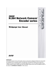
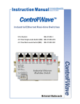
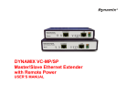
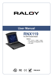
ZN-S100V/ZN-S1000VE HARDWARE MANUAL
2010/2-1 D1A.02
1 ZN-S100V/ZN-S1000VE HARDWARE MANUAL
Table of Contents
1. Introduction............................................................................................................. 3
2. Product Description ................................................................................................. 4
2.1. Function specification .............................................................................................. 4
3. Installation & Configuration ..................................................................................... 6
3.1. Package contents...................................................................................................... 6
3.2. Components ............................................................................................................. 7
3.2.1. Front Panel ..................................................................................................................... 7
3.2.2. Rear Panel ...................................................................................................................... 9
3.3. Basic Connection .................................................................................................... 13
3.4. Serial Number / MAC Address................................................................................ 14
4. Operation Description............................................................................................ 15
4.1. Factory Default Settings ......................................................................................... 15
4.2. Rebooting ............................................................................................................... 15
5. Power over Ethernet (PoE) ..................................................................................... 17
5.1. PoE compatibility ................................................................................................... 17
5.2. Power classification................................................................................................ 17
6. Electrical characteristics ......................................................................................... 18
6.1. Operating conditions.............................................................................................. 18
6.2. Power consumption ............................................................................................... 18
7. Dimensions............................................................................................................ 19
2010/2-1 D1A.02
2 ZN-S100V/ZN-S1000VE HARDWARE MANUAL
1. Introduction
ZN‐S100V and ZN‐S1000VE are encoder module. ZN‐S100V/ZN‐S1000VE compress video/audio data and transmit the compressed video/audio data through the network in real time. ZN‐S100V/ZN‐S1000VE provides a high quality video image with a limited bandwidth and storage capacity. ZN‐S100V/ZN‐S1000VE also supports dual stream mode, and is equipped with built‐in VCA (Video Content Analysis) feature. These products are ideally suited for a wide range of surveillance and remote monitoring applications. Main features are highlighted below. Main features • High Quality Compression in real time streaming • H.264, MPEG‐4, and MJPEG encoding at D1 in real time Network • RTP/RTSP and unicast/multicast are supported. Streaming •Dual streaming mode such as different codec/resolution/bit rate and so on. •De‐interlacing on DSP. Video/Audio • Loop‐out video for external monitors • Burnt‐In text is supported • ZN‐S1000VE supports two ways audio. (ZN‐S100V is not available.) Additional Features • RS‐485/422 serial port for Pan/Tilt/Zoom. (Except ZN‐S100V) • RS‐232C serial port for some devices like a POS terminal. (Except ZN‐S100V) • Motion detection by hardware. • On Screen Display (OSD) by hardware. • POE(Power Over Ethernet) is supported. (Optional) VCA • VCA Presence (Included as Standard) • VCA Surveillance (Optional) SDK • Two types (RTSP and HTTP‐API) are provided for application development. 2010/2-1 D1A.02
3 ZN-S100V/ZN-S1000VE HARDWARE MANUAL
2. Product Description
2.1. Function specification
Audio Video ZN‐S100V/ZN‐S1000VE series specification is shown as following Table. ZN‐S100V/ZN‐S1000VE series Item ZN‐S100V ZN‐S1000VE Number of Streams Dual Stream, Configurable Input channel 1ch Output Channel 1 Loop Out Compression H.264, MPEG‐4, MJPEG Selectable per Stream Resolution D1, 4CIF, CIF, QCIF, VGA, QVGA Compression FPS 25/30fps@D1 (PAL/NTSC) Input / Output Not available 1/1ch Data Format Not available PCM & G.711 Network 10/100 Base‐T DI/DO Not available 2/2 RS‐232C Not available Support RS‐485 Not available Support De‐interlacing Support (Hardware Encoding Engine) Motion Detection Support (DSP) OSD Support (DSP) Protocols SNTP, DHCP, UDP, TCP, RTP, RTSP(unicast,multicast) External Storage Not available USB 2.0 & SD Memory card slot
※ SD Card is not included Power Source 12V DC (DC Jack) 12V DC (DC Jack) Power over Ethernet Support ‐ IEEE 802.3af (Optional) Operating Temperature 0 ˚C ~ 50 ˚C (32˚F ~ 122 ˚F) Operating Humidity Up to 85% RH (Non‐condensing) Dimension 74.6(W) x 26.3(H) x 106.6(D) 103.4(W) x 37.7(H) x 141.4(D)
mm mm Weight TBD VCA (Video Content Analysis) VCA Presence (Included as Standard) TBD High Performance Advanced Tracking Algorithm, Low False Alarm Rate Easy to Use Intuitive Web Browser Interface Detection Zones Multi‐segment Polygons and Lines 2010/2-1 D1A.02
4 ZN-S100V/ZN-S1000VE HARDWARE MANUAL
On‐screen Display Real‐time Display of Tracking Data and Events VCA Surveillance (Optional) Detection Behavior Direction, Stopping, Loitering, Entering, Exiting, Appear, and Disappear Filters 3D Behavior Perspective Corrected Size and Speed Filters Statistics Counting Functions and Other Statistics Meta Data Binary XML Format Image Stabilization (Optional) Electronic Stabilization 2010/2-1 D1A.02
Removes Camera Sway 5 ZN-S100V/ZN-S1000VE HARDWARE MANUAL
3. Installation & Configuration
3.1. Package contents
The Package contains the following. Please make sure all listed items are included in the box. ZN‐S100V or ZN‐S1000VE ‐‐‐‐‐‐‐‐‐‐‐‐‐‐‐‐‐‐‐‐‐‐‐‐‐‐‐‐‐‐‐‐‐‐‐‐‐‐‐‐‐‐‐‐‐‐‐‐‐‐‐ 1 LAN Cable (Cross type 1m) ‐‐‐‐‐‐‐‐‐‐‐‐‐‐‐‐‐‐‐‐‐‐‐‐‐‐‐‐‐‐‐‐‐‐‐‐‐‐‐‐‐‐‐‐‐‐‐‐ 1 9port Terminal block plug (except ZN‐S100V) ‐‐‐‐‐‐‐‐‐‐‐‐‐‐‐‐‐‐‐‐‐‐‐‐‐‐2 DC 12V Power Adapter‐‐‐‐‐‐‐‐‐‐‐‐‐‐‐‐‐‐‐‐‐‐‐‐‐‐‐‐‐‐‐‐‐‐‐‐‐‐‐‐‐‐‐‐‐‐‐‐‐‐‐‐‐‐1 AC100~AC240V power cable‐‐‐‐‐‐‐‐‐‐‐‐‐‐‐‐‐‐‐‐‐‐‐‐‐‐‐‐‐‐‐‐‐‐‐‐‐‐‐‐‐‐‐‐‐‐ 1 2010/2-1 D1A.02
6 ZN-S100V/ZN-S1000VE HARDWARE MANUAL
3.2. Components
3.2.1. Front Panel
③
④ ① ⑤
②
Figure 1. Front Panel of ZN‐S1000VE ① ②
⑧
⑥
⑦
Figure 2. Front Panel of ZN‐S100V ① Video Input BNC Connector (Vin 1) It is mainly used for video inputs. ② Video Output BNC Connector This connector is used for loop‐out of video input. ③, ④ Indicator LED (Status, Data) Status and Data indicators display the following system information. Status LED has a yellow, a green and an orange color. Data LED has a red, a green and a dark orange color. 1. Power off Item Status Data Power OFF OFF OFF 2010/2-1 D1A.02
7 ZN-S100V/ZN-S1000VE HARDWARE MANUAL
2. System initialization Item Status Data In Process Off Blinking Dark Orange Normal State Orange Off Abnormal State Orange Dark Orange 3. Kernel booting up Item Status Data In Process Orange Green Normal State Orange Off Abnormal State Orange Green Status Data Normal Blinking Green Off Abnormal Green Off Status Data Normal Orange blinks at every 1 second Off High Overload Orange blinks at every 1 second Red 4. Video streaming service Item 5. DSP operation status Item ⑤ SD Memory Slot It is a memory card slot for external storage. ⑥ LAN Connector (Ethernet) It is a RJ45 LAN connector for 10/100 Base‐T Ethernet. This socket can also be used to power the ZN‐S100V/ZN‐S1000VE via PoE (Optional). Figure 3. RJ45 LAN connector ⑦ Power Adaptor Connector (DC 12V) ZN‐S100V needs a DC 12V 1A adapter for power supply. ‐
+
2010/2-1 D1A.02
8 ZN-S100V/ZN-S1000VE HARDWARE MANUAL
Figure 4. Power Connection ⑧ Reset Switch (Reset) Reset switch is used for restarting ZN‐S100V/ZN‐S1000VE or resetting ZN‐S100V/ZN‐
S1000VE as Factory Default (FD). Refer to ‘4.1. Factory Default Settings’ for detailed procedures. 3.2.2. Rear Panel
① ②
③ ⑤
④ Figure 5. Rear Panel of ZN‐S1000VE ① USB Port ZN‐S1000VE provides one USB port which can connect to the USB device as an external storage device. It can be connected to multiple USB devices using USB HUB. ② Terminal for a audio output/input, an alarm, a sensor and serial devices (Except ZN-S100V)
DI GND
DI ch2
DI ch1
Ain GND
Ain AOut
AOut GND
DO ch1
DO ch2
DO GND
2010/2-1 D1A.02
RS‐232C RX RS‐232C TX RS‐232C GND RS‐485 GND RS‐485 D‐ RS‐485 D+ 9 ZN-S100V/ZN-S1000VE HARDWARE MANUAL
Figure 6. Terminal block 1. Audio Input ZN‐S1000VE has one channel mono audio input. 2. Audio Output ZN‐S1000VE has one channel mono audio output. As the output power for the audio is low, amplifier speaker is needed (Do not use a headphone or earphone directly to the camera). 3. Digital Input (DI1, DI2) ZN‐S1000VE supports two digital inputs. It can be connected either voltage type sensor or relay type sensor as following Figure 7. and Figure 8. Do not use voltage and relay type sensor together. Please pay attention to electric characteristics during installation. (Detailed instructions are being prepared.) ch1 Sensor 1 ch2 Sensor 2 GND
1 2 Figure 7. Voltage Type Digital Input Connection ch1 Sensor 1 ch2 Sensor 2 GND
1 2 Figure 8. Relay Type Digital Input Connection 4. Digital Output (DO1, DO2) DO devices can be connected as following Figure 9. 2010/2-1 D1A.02
10 ZN-S100V/ZN-S1000VE HARDWARE MANUAL
Please pay attention to electric characteristics during installation. (Detailed instructions are being prepared.) ch1 LED 1
ch2 LED 2
+12V GND
1 2 Figure 9. Digital Output Connection 5. RS‐485 The RS‐485 serial port consists of DATA+, DATA‐ and GND as following Figure 10. DATA+
DATA+ DATA‐
GND
DATA‐
GND
PTZ Camera + ‐ Figure 10. RS‐485 Connection 6. RS‐232C RS‐232C Terminal Block is used for some devices such as POS terminal block. RX TX
RX
TX GND
GND
RX TX Figure 11. RS‐232C Connection ③ LAN Connector (Ethernet) This is a RJ45 LAN connector for 10/100 Base‐T Ethernet. This socket can also be used to power the ZN‐S100V/ZN‐S1000VE via PoE (Optional). 2010/2-1 D1A.02
11 ZN-S100V/ZN-S1000VE HARDWARE MANUAL
④ Power Adaptor Connector (DC 12V) ZN‐S1000VE needs a DC 12V 1A adapter for power supply. ‐
+
Figure 12. Power Connection ⑤ Reset Switch (Reset) Reset switch is used for restarting ZN‐S100V/ZN‐S1000VE or resetting ZN‐S100V/ZN‐
S1000VE as Factory Default (FD). Refer to ‘4.1. Factory Default Settings’ for detailed procedures. 2010/2-1 D1A.02
12 ZN-S100V/ZN-S1000VE HARDWARE MANUAL
3.3. Basic Connection
SD memory
Camera
External Monitor
Figure 13. ZN‐S1000VE’s Front Panel Connection Sensor 1‐2 MIC
USB memory DC Adapter
LAN Amp Speaker
Alarm
PTZ Camera Figure 14. ZN‐S1000VE’s Rear Panel Connection Normal operation may not be possible if temperature or humidity exceed levels recommended in the ZN‐S100V/ZN‐S1000VE specification. 2010/2-1 D1A.02
13 ZN-S100V/ZN-S1000VE HARDWARE MANUAL
3.4. Serial Number / MAC Address
Serial number and MAC address is attached on the bottom as shown in Figure 15. 550012345
MAC 00:1C:B8:C0:14:B1
MAC Address
ZN-S1000VE P1331010100000-121
Serial Number
Figure 15. Serial Number/ MAC Address 2010/2-1 D1A.02
14 ZN-S100V/ZN-S1000VE HARDWARE MANUAL
4. Operation Description
4.1. Factory Default Settings
Factory default settings are as follows: • IP address: 192.168.xx.yy (Refer to 2.3 Serial Number / MAC Address) • Mask: 255.255.0.0 • Gateway: 192.168.0.1 • User ID: root • Password: pass MAC address = 00‐1C‐B8‐C0‐14‐B1 → IP address = 192.168.35.69 Convert the Hexadecimal number to Decimal number
To perform the FD (Factory Default) initialization: ZN‐S1000VE Refer to ‘Figure 1.’ 1. Turn off the power. 2. Press and hold the Reset button 3. Turn on the power. 4. Release the Reset button when the Status LED’s color is orange and the Data LED’s color is red. 5. Wait for the system to reboot. ZN‐S100V Refer to ‘Figure 2.’ and ‘Figure 3.’ 1. Turn on the power (The Status LED is on). 2. Press and hold the Reset button within 1 second. 3. Release the Reset button after 3 seconds. 4. Wait for the system to reboot. 4.2. Rebooting
To reboot the system: ZN‐S1000VE Refer to ‘Figure 1’ 2010/2-1 D1A.02
15 ZN-S100V/ZN-S1000VE HARDWARE MANUAL
1. Press Reset. The red Data LED will blink several times. When Reset function is activated, the red Data LED will turn on. User may stop pressing Reset at this point. 2. When “Reset” function has been completed, the green Data LED will turn on and Status LED and Data LED will blink together. ZN‐S100V Refer to ‘Figure 2’ and ‘Figure 3’ 1.While the camera is in use, press and hold the Reset button. (Both the Status and Network LEDs are on.) 2.Release the Reset button after 3 seconds. 2010/2-1 D1A.02
16 ZN-S100V/ZN-S1000VE HARDWARE MANUAL
5. Power over Ethernet (PoE)
The PoE module used in ZN‐S100V/ZN‐S1000VE is commercially available module without modification. The standard ZN‐S100V/ZN‐S1000VE does not include PoE module in it. PoE module is included on the request of a customer. For the detailed information, please contact sales person. 5.1. PoE compatibility
With non Power Sourcing Equipment (PSE) When it is connected with non PSE, the power adaptor should be connected. With power adaptor Connecting both PSE and power adaptor does not do any harm to the products. Disconnecting power adaptor while it is operating does not stop operation. The product continues to work without rebooting. 5.2. Power classification
The PoE Power Class supported by ZN‐S100V/ZN‐S1000VE is Class 0. Table 1 shows IEEE 802.3af power classes. Class Usage Minimum Power Levels Maximum Power Levels at Output at the PSE the Powered Device 0 Default 15.4W 0.44 to 12.95W 1 Optional 4.0W 0.44 to 3.84W 2 Optional 7.0W 3.84 to 6.49W 3 Optional 15.4W 6.49 to 12.95W 4 Reserved for Future Use Treat as Class 0 Reserved for Future Use Table 1. IEEE 802.3af PSE and Powered Device Power Classifications 2010/2-1 D1A.02
17 ZN-S100V/ZN-S1000VE HARDWARE MANUAL
6. Electrical characteristics
6.1. Operating conditions
Parameters Min Typical Max Units Video Peak to peak amplitude
input range Sync amplitude 0.25 1 2 V 72 286 572 mV ‐ ‐ ±7 % of line length
±800 Hz Horizontal lock range Color sub‐carrier Lock‐
in range Audio input range ‐ TBD TBD TBD Vp‐p 0 ‐ 50 ºC TBD ‐ TBD % On‐state current ‐ ‐ TBD mA Operating Voltage ‐ ‐ TBD VDC Ambient Operating Temperature Ambient Operating Humidity D/O (isolated) ‐ Table 2. Operating conditions 6.2. Power consumption
Item ZN‐S100V ZN‐S1000VE Input Voltage 12 V 12 V Current TBD TBD Consumption TBD TBD Table 3. Power consumption Overvoltage and overcurrent will cause a severe damage to the device or even a fire. 2010/2-1 D1A.02
18 ZN-S100V/ZN-S1000VE HARDWARE MANUAL
7. Dimensions
ZN‐S100V 94.6
74.6
106.6
98
26.3
Unit : mm
2010/2-1 D1A.02
19 ZN-S100V/ZN-S1000VE HARDWARE MANUAL
H.264 Network Video Encoder
ZN‐S1000VE 141.4
121.7
37.7
103.4
1CH Encoder
Ain
1
DI
1 2
RS-232
Rx Tx
DC12V
Status
SD
Data
Vin
Vout
USB
Ethernet
Reset
1 2 C
1
Aout
DO
RS-485
Unit : mm
2010/2-1 D1A.02
20