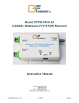
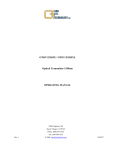
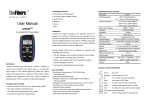
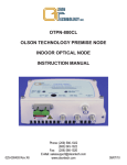
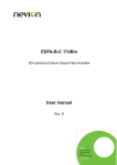
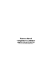
1
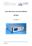
OTEB-CO-B Series Booster EDFA OPERATING MANUAL 24926 Highway 108 Sierra Village, CA 95346 Phone: (800) 545-1022 Fax: (209 586-1022 025-000533 Rev X6 E-Mail: [email protected] 27 Apr 2010 TABLE OF CONTENTS SAFETY .......................................................................................................................................................................................3 Safety Precautions ...................................................................................................................................................................3 High Voltage ............................................................................................................................................................................3 Shock Hazard...........................................................................................................................................................................3 INTRODUCTION..........................................................................................................................................................................4 Figure 1 -Block Diagram of OTEB-CO-B Series EDFA ................................................................................. 4 GENERAL FEATURES................................................................................................................................................................5 PANEL LAYOUTS .......................................................................................................................................................................5 Figure 2 - EDFA Front Panel Layout ............................................................................................................... 5 Figure 3 - EDFA Rear Panel Layout ................................................................................................................ 5 Technical Specifications...........................................................................................................................................................6 Figure 4 - Typical CATV CNR Degradation..................................................................................................... 6 STATUS DISPLAY PANEL OPERATION ...................................................................................................................................7 Optical Input Power..................................................................................................................................................................7 Optical Output Power ...............................................................................................................................................................7 Laser Temperature...................................................................................................................................................................7 Laser Bias ................................................................................................................................................................................7 Laser Heating/Cooling..............................................................................................................................................................7 TEC..........................................................................................................................................................................................7 Voltage.....................................................................................................................................................................................7 Serial Number ..........................................................................................................................................................................7 IP Address for RS-232 Connector............................................................................................................................................7 DESCRIPTION OF STATUS ALARM..........................................................................................................................................8 NOTES ON OPERATION ............................................................................................................................................................8 025-000533 Rev X6 2 www.olsontech.com SAFETY Safety Precautions The OTEA-CO-B EDFA emits invisible radiation that can cause permanent eye damage. AVOID DIRECT EXPOSURE TO BEAM. Operate the transmitter only with the proper optical fiber installed in the transmitter optical connector. Power to the OTEA-CO-B EDFA should be turned off or preferably, disconnected whenever the optical connector cover is opened and there is no installed fiber (as when the fiber connector is being installed or removed from the optical connector). When the amplifier is working in normal state, the output power of light with wavelengths in the invisible range (infrared light) may exceed +26dBm (400mW). Therefore, to avoid damaging your eyes, do not look into the output port of the EDFA directly. NEVER look at the end of the fiber to see if light is coming out. NEVER! Most fiber optic laser wavelengths (1310nm and 1550nm) are totally invisible to the unaided eye and will cause permanent damage. Always use instruments, such as an optical power meter, to verify light output. “Optical instrument” includes magnifying glasses, microscopes, etc. NEVER look into the output of the EDFA or a fiber connected to an EDFA. NEVER clean an optical connector with optical power present. NEVER look into or use any optical instrument to view the distant end of a fiber that may be connected directly or via an optical splitter, to a transmitter or EDFA that may be operating. This specifically applies to fibers that are to be connected to receivers (such as the OTPN-1000) or other devices at any distance from the laser transmitter or EDFA. ALWAYS read the product data sheet and the laser safety label before powering the product. Note the operation wavelength, optical output power and safety classifications. If safety goggles or other eye protection are used, be certain that the protection is effective at the wavelength emitted by the device under test BEFORE applying power. ALWAYS connect a fiber to the output of the device BEFORE power is applied. Power should never be applied without an attached fiber. If the device has a connector output, a connector should be attached that is connected to a fiber. This will ensure that all light is confined within the fiber waveguide, virtually eliminating all potential hazard. High Voltage The inside of the OTEA-CO-B EDFA contains no user serviceable parts. There is exposed high voltage inside this unit. Only authorized factory service technicians should open the unit with power applied. Shock Hazard The OTEA-CO-B EDFA is designed for indoor use only. Direct exposure to moisture must be avoided. If you have questions about laser safety procedures, please call Olson Technology before powering your product. The fiber amplifier is sensitive equipment. Therefore, please do not open the case of the amplifier to avoid damaging the internal component devices. Opening the case of the amplifier without the written permission of Olson Technology, Inc., will void the warranty. 025-000533 Rev X6 3 www.olsontech.com INTRODUCTION Olson Technology, Inc., a major manufacturer in fiber optic components, provides a wide range of Erbium Doped Fiber Amplifiers (EDFA’s), for 1550nm HFC networks. They feature low noise figure, stable output power and excellent environmental stability. EDFA’s are comprised of two main parts: the gain module and the external control system. The gain module amplifies the optical signal in 1550nm wavelength band (1540-1560nm typically). It is made of high quality optical components, and carefully designed to maximize overall performance. Low power EDFA’s may only have a single pump, while high power units can have up to three pumps. The external control system allows the operator to ensure that the gain module is working optimally. Controlled by microprocessor, it monitors the states of the gain module and adjusts all the parameters to ensure a stabilized output power of the gain module. Moreover, this system provides warnings via the front panel indicator LED and a digital display. The LCD on the front panel shows the detailed working parameters of the EDFA. This information can also be accessed via the standard RS-232 interface via an external computer. Figure 1 - Block Diagram of OTEB-CO-B Series EDFA 025-000533 Rev X6 4 www.olsontech.com GENERAL FEATURES The Olson Technology Model OTEB-CO-BYXX EDFA incorporates a reliable optical output drive circuit, and laser TEC to provide a highly reliable Erbium-doped optical amplifier. Built-in microprocessor software allows the unit to monitor a number of system parameters, including: laser status, system alarms, network management, Thermoelectric Cooler (TEC) circuit operation, etc. If a failure is detected, the power supply for the laser will shut down automatically, a red LED indicator will light, and the front panel display will show the nature of the problem. The microprocessor software allows interconnection to a computer using the standard RS-232 interface. The EDFA is housed in a 1RU 19" rack mount configuration with an integrated 85-254VAC or -48VDC power supply. PANEL LAYOUTS Figure 2 - EDFA Front Panel Layout Figure 3 - EDFA Rear Panel Layout 025-000533 Rev X6 5 www.olsontech.com Technical Specifications Typical Models* 115 116 117 118 119 120 121 122 123 124 221 419 Number of Outputs 1 1 1 1 1 1 1 1 1 1 2 4 Fixed Output Power (dBm) 15 16 17 18 19 20 21 22 23 24 21 19 Input Power Power Range (dB) -10 to +10 Max Alarm (dBm) 10 Min Alarm (dBm) -10 Wavelength (nm) 1540 to 1560 Output Stability (dB) ±0.3 Noise 0dBm Input (dB) ≤4.5 ≤5.0 ≤5.3 Figure +6dBm Input (dB) ≤5.5 ≤6.0 ≤6.5 Polarization (dB) 0.2dB Polarization-Mode Dispersion (ps) 0.5ps Reflection Loss (dB) 40dB Minimum Optical Connector SC/APC Standard Network Management Interface RS-232 Power (W) 50W Maximum Voltage (VAC) 85 to 264 Voltage (VDC) -48 Typical Working Temperature (°C) +5 to 45 Storage Temperature (°C) 0 to +55 Dimensions 19" x 15" x 1.75" (483mm x 381mm x 44mm) Contact factory for other options Figure 4 - Typical CATV CNR Degradation 025-000533 Rev X6 6 www.olsontech.com STATUS DISPLAY PANEL OPERATION The microprocessor software monitors the function of a number of system parameters. Pressing the ▼and▲buttons allows the LCD to display key working parameters sequentially. Optical Input Power Input power: INPUT = display input power (dBm) Input power = +10dBm = >alarm Input power = -10dBm => display NO INPUT =>shut down the power supply of the laser. Input power = 0dBm => reach fixed output power. Optical Output Power Output: OUTPUT = display output power (dBm) Tolerance = ±0.2dBm No input = power supply of the laser will be shut down automatically => display NO INPUT => NO OUTPUT Laser Temperature Laser temperature: TEMP = laser temp is set to operate in the range of 20-30°C if exceeded => LCD will display” READY” => red LED indicator will light, and the power supply of the laser will shut down automatically. Laser Bias Bias: BIAS = Bias is the key index of the laser, if it exceeds the fixed range power supply of the laser, the power supply will be shut down automatically to protect the laser. Laser Heating/Cooling Cooling/heating: COOLING/HEATING = standard temperature for laser 25°C TEC Thermoelectric cooler 25°C At heat circumstance, LCD display => COOLING At cool circumstance, LCD display =>HEATING Voltage +5V Voltage: +5V READS… => ±0.5V alarm -5V Voltage: -5V READS… => ±0.5V alarm Serial Number Displays the serial number of the EDFA. IP Address for RS-232 Connector The IP address code can be set by the operator via the RS-232 connector on the rear panel. 025-000533 Rev X6 7 www.olsontech.com DESCRIPTION OF STATUS ALARM The front panel indicator LED indicator may be red, green, or off. When the LED is green the EDFA is operating properly. When the LED is off, the unit is off. A red LED indicates an alarm condition. The alarm condition will be displayed on the display panel. With proper power supply, if the EDFA is functioning normally and the LED indicator is red, the digital panel will display “READY KEY OFF. Turn on with the key. The display shows KEY OFF for 10 seconds, then the LED indicator changes to green. Pressing the STATUS button displays the following parameters: Input power ≤ -10 dBm, display => NO INPUT; the EDFA cannot be turned on and the LED is red. If any fault listed above has occurred, there will be an alarm. The microprocessor will shut down the laser automatically, and the digital panel will display the cause of the fault. In order to protect the laser, there is a time-delay function. After turning the laser on with the key, the laser will start to work after 10 seconds. NOTES ON OPERATION The EDFA should have good grounding and grounding resistance to 4Ω. According to the international standard, on an AC three-wire plug, the middle wire is the grounding wire. The EDFA incorporates a high performance, high reliability, switching power supply with over-voltage protection. The microprocessor monitors the output DC voltage. If the fuse blows, the unit should be returned to Olson for service. In order to keep the reflection loss to <-55dB, the EDFA uses SC/APC optical connectors. Other connector types, such as FC/PC, cannot be used with the EDFA. Keep the connector clean when installing the optical cables. Clean it with lint-free tissue with anhydrous alcohol after several rounds of connection/disconnection from the unit. NEVER clean the optical connectors with the unit powered! 025-000533 Rev X6 8 www.olsontech.com