1
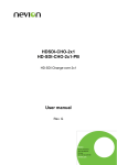
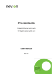
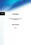
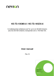
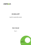
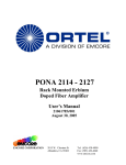
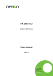
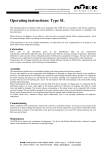
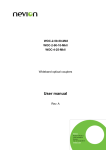
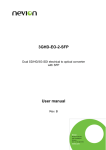
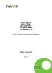
EDFA-B-C 17dBm SDI optimized Erbium Doped Fiber Amplifier User manual Rev. D Nevion Nordre Kullerød 1 3241 Sandefjord Norway Tel: +47 33 48 99 99 nevion.com EDFA-B-C 17dBm Rev. D Nevion Support Nevion Europe Nevion USA P.O. Box 1020 3204 Sandefjord, Norway Support phone 1: +47 33 48 99 97 Support phone 2: +47 90 60 99 99 1600 Emerson Avenue Oxnard, CA 93033, USA Toll free North America: (866) 515-0811 Outside North America: +1 (805) 247-8560 E-mail: [email protected] See http://www.nevion.com/support/ for service hours for customer support globally. Revision history Current revision of this document is the uppermost in the table below. Rev. Repl. Date Sign D C B 0 A C B 0 A - 2015-10-22 2015-10-12 2014-05-21 2012-01-11 2008-02-01 OEH OEH OEH SHH Change description Added notice about fibre cleaning Corrected dip switch settings Added LED chapter Initial revision. Initial revision (not published) nevion.com | 2 EDFA-B-C 17dBm Rev. D Contents Revision history ........................................................................................................ 2 1 Product overview ................................................................................................... 4 2 Specifications ........................................................................................................ 5 2.1 Optical Characteristics .................................................................................................. 5 2.2 Power consumption ....................................................................................................... 5 2.3 Environmental conditions .............................................................................................. 5 3 Cautions ................................................................................................................ 6 3.1 Laser Safety .................................................................................................................. 6 4 Configuration ......................................................................................................... 7 4.1 Dip switch settings ........................................................................................................ 7 4.1.1 Common dip switches ................................................................................................ 7 4.1.2 Constant power mode ................................................................................................ 7 4.1.3 Constant gain mode ................................................................................................... 7 4.2 Status by LED’s............................................................................................................. 8 4.2.1 LED status description ............................................................................................... 8 4.3 GPI................................................................................................................................ 9 4.4 RS232 control ..............................................................................................................10 4.5 Lid operated switches...................................................................................................11 4.6 Key switch ....................................................................................................................11 5 Connections ........................................................................................................ 12 6 Operation............................................................................................................. 13 6.1 Introduction ..................................................................................................................13 6.2 EDFA theory ................................................................................................................13 6.3 Operation modes..........................................................................................................13 General environmental requirements for Nevion equipment .................................. 15 Product Warranty.................................................................................................... 16 Appendix A Materials declaration and recycling information .................................. 17 A.1 Materials declaration ....................................................................................................17 A.2 Recycling information...................................................................................................17 nevion.com | 3 EDFA-B-C 17dBm Rev. D 1 Product overview The Flashlink EDFA-B-C 17dBm is an erbium doped fiber amplifier with a special control circuit making it better for SDI signals than normal EDFAs. It is a +17dBm booster that is typically used at the beginning or in the middle of a link. At the receiving end of a link, a low power / low noise preamp would typically be needed instead. The EDFA is unidirectional by nature, but can amplify up to 40 DWDM channels on a single fiber, at 100GHz spacing. Ideal gain flatness is achieved with input power close to the nominal input power. Various safety measures are implemented, like automatic shutdown if rear lid is opened to access the fiber connectors, or manual shutdown by the use of GPI, GYDA, RS422 or turning the safety key to the “off” position. There is also a reduced output power mode that can be entered with the use of GPI, GYDA or RS422 control. EDFA can also be directly controlled over RS232, bypassing the Flashlink features. The key, lid, GPI and GYDA/RS422 still operate the shutdown and reduced output power modes, even when using direct RS232 control. EDFA status is monitored by use of LEDs, GPIO and RS422/GYDA. Figure 1: EDFA block diagram nevion.com | 4 EDFA-B-C 17dBm Rev. D 2 Specifications 2.1 Optical Characteristics Nominal input power Maximum input power Minimum input power Total output power Gain flatness Noise figure Wavelength range Number of DWDM ch. Polarization dependant gain Polarization Mode Dispersion Input/Output return loss (pump off) -6dBm +4dBm -10dBm 17dBm +/- 1.5dBm at Pin from -10dBm to 0dBm Max. 1.0dB at Pin=-6dBm, Pout=17dBm Max. 5.0dB at Pin from -10dBm to 0dBm Max. 6.0dB at Pin=-6dBm, Pout=17dBm Full C-band, 1529 to 1562nm Min. 40 channels at 100GHz spacing Max. 0.5dB Max. 0.5ps Min. 35dB 2.2 Power consumption Maximum power consumption: <9W (+5V) 2.3 Environmental conditions Operation temperature range Operation without damage temperature range 0°C – 45°C 0°C – 55°C nevion.com | 5 EDFA-B-C 17dBm Rev. D 3 Cautions 3.1 Laser Safety This unit is capable of emitting dangerous levels of light. DO NOT UNDER ANY CIRCUMSTANCES LOOK AT THE OUTPUT OF THE UNIT OR FIBRE ATTACHED TO THE UNIT! Containing a Class IIIb assembly, use the utmost case when changing connections, and always turn the unit completely off before inspecting or cleaning any connectors which are attached to the unit’s output. 3.2 Fibre Cleaning It is imperative that the fibre ends of the EDFA are kept clean of dust and dirt, to avoid insertion loss and back reflection. Insertion loss will take away margin from the optical budget, while back reflection will lead to excessive bias currents (due to output power regulation being dependent on power measured at the output, after isolator and gain flattening filter). This also means that for output power testing, the output should be properly terminated with minimal back reflection. nevion.com | 6 EDFA-B-C 17dBm Rev. D 4 Configuration 4.1 Dip switch settings The dip switches are also documented on the front of the EDFA The following dip switches change the meaning of the other dip switches: 4.1.1 Common dip switches Function OFF Function ON Comment 1 Pos G_P Name Constant Gain Constant Power 7 A_M Manual RS232 control 8 OVR Autonomous and/or GYDA/DIP control Gyda control Fundamental working mode for EDFA. Set OFF to use the RS232 port in the front of the EDFA to control parameters like function (constant power, gain or drive), When ON, only dip switches can change configuration. GYDA can only monitor. To control with GYDA, set to OFF. Dip switches active 4.1.2 Constant power mode In this mode, dip switches 1 and 8 are set ON, 7 is OFF. Function ON Comment 2 Pos S_T Name SDI optimised Function OFF Telco optimised 3 4 5 6 G3 G3 G2 G1 Add 14dBm Add 2dBm Add 1dBm Add 0.5dBm Add 10dBm Add 0dBm Add 0dBm Add 0dBm Chooses between signal types present on the fiber. For a low number of SDI signals which might display pathological signals (shifts in average power), set dip ON. For many channels with fast adaptation to varying input levels, set dip OFF. These dip switches set the output power, from a minimum of +10dBm to a maximum of +17.5dBm (0.5dB step). 4.1.3 Constant gain mode In this mode, dip switches 1 and 7 are set OFF, while 8 is set ON. Pos 2 3 4 5 6 Name S_T G3 G2 G1 G0 Function OFF Not used Add 18dB Add 4dB Add 2dB Add 1dB Function ON Not used Add 10dB Add 0dB Add 0dB Add 0dB Comment No effect in Constant Gain mode. These dip switches set the gain, from a minimum of 10dB to a maximum of 25dB (1dB step). nevion.com | 7 EDFA-B-C 17dBm Rev. D 4.2 Status by LED’s The status of the module can be easily monitored visually by the LEDs at the front of the module. The LEDs are visible through the front panel as shown below. Status TEMP LOS & LOP LASER Figure 2: Panel indicator overview (Text not printed on the front panel) 4.2.1 LED status description The functions of the different LEDs are described in table below. Diode \ state Red LED Status Module is faulty TEMP LOS & LOP LASER Laser temperature alarm Loss of input signal Laser fail Yellow LED Ambient temperature alarm Loss out output signal (mute/bypass) Laser disabled (mute/bypass) Green LED No light Module is OK Module has Module has power no power Temperature is OK Signal is OK Laser is OK. nevion.com | 8 EDFA-B-C 17dBm Rev. D 4.3 GPI These outputs can be used for wiring up alarms for third party control systems. The GPI outputs are open collector outputs, sinking to ground when an alarm is triggered. The GPI connector is shown in figure 7. There are two GPI inputs, one for muting output power (power goes to below safe limit) and one for complete disable (same function as key switch, lid and software disable command). Electrical Maximums for GPI outputs Max current: 100mA Max voltage: 30V EDFA-B-C 17dBm module GPI pinning: Signal Name STATUS LOS Loss of input signal/power LOP Loss of output signal/power TERM Temperature out of range LASER Laser bias current out of range DIS DISABLE (completely shut off bias current to the laser). MUTE MUTE (output power goes below class 1 limits). Ground 0 volt pin Pin # Mode Direction Pin 1 Open Collector Output Pin 2 Open Collector Output Pin 3 Open Collector Output Pin 4 Pin 5 Open Collector Output Open Collector Output Pin 6 TTL, 0V = active level Input Pin 7 TTL, 0V = active level 0V. Input Pin 8 Figure 3: GPI Outlet nevion.com | 9 EDFA-B-C 17dBm Rev. D 4.4 RS232 control If dip switch 7 (“A_M”) is set OFF (Manual), the GYDA/dip switch control over the EDFA will halt and the RS232 input will be enabled (RS232 output is always on). Bitrate 9600, 8N1 (8 databits, no parity, 1 stop bit). A typical prompt will be “MSA::EDFA>”. When the prompt returns, the module is ready for a new command. There is an option to set the bitrate of the EDFA module to something else than 9600, but this will disable autonomous/GYDA operation until reset back to 9600. The following table lists the most useful commands (the HELP command will list all commands): Command GET_STATUS Example response Comment MODULE:DISABLED DI CONTROL: AGC ALARMS: NORMAL LD: NORMAL GET_INFO GET_BAUD Bit rate of serial port. SET_BAUD [4800,9600, 14400,19200,38400] GET_ECHO OK SET_ECHO [ON,OFF] OK GET_MODE MODE: G 18.80 dB SET_MODE [P,G,C,M]<value> OK Power in dBm, Gain in dB, Current in mA or M***MISSING*** Laser diode power measurement MPD1: -1.82 dBm, 6.58E-01 mW MPD2: -8.29 dBm, 1.48E-01 mW 1: input, 2: output GET_LD_POW GET_MPD [1,2,ALL] Echoes characters back to the terminal. Off by default GET_LD_CRNT Laser diode bias current measurement GET_ALARM_LD_CRNT Alarm limit for laser diode bias current SET_ALARM_LD_CRNT <value,D> GET_LD_TEC Laser diode thermal stabiliser current GET_TPUMP TPUMP: 25.47 C GET_ALARM_TPUMP_HI ALARM_TPUMP_HI: 30.00 C SET_ALARM_TPUMP_HI <value,D> GET_ALARM_TPUMP_LO OK SET_ALARM_TPUMP_LO <value,D> GET_TCASE OK TCASE: 31.03 C Ambient temperature GET_ALARM_TCASE_HI ALARM_ TCASE_HI: 70.00 C Upper alarm limit SET_ALARM_TCASE_HI <value,D> GET_ALARM_TCASE_LO OK SET_ALARM_TCASE_LO <value,D> GET_LOS_SWD OK ALARM_TPUMP_LO: 20.00 C ALARM_ TCASE_LO: 0.00 C SET_LOS_SWD [ON,OFF,CP] GET_LOS Threshold for loss of signal. Input power below this triggers muting of output power. SET_LOS <value> HELP … The complete list of commands nevion.com | 10 EDFA-B-C 17dBm Rev. D 4.5 Lid operated switches If the lid covering the fiber connectors on the backplane should be opened, the EDFA will automatically disable. This is done both by a switch in direct contact with the lid, and by software through the use of an optical sensor. 4.6 Key switch The key switch in the front of EDFA-B-C 17dBm can be used to disable the EDFA. The key can only be removed when the switch is in the OFF position. nevion.com | 11 EDFA-B-C 17dBm Rev. D 5 Connections The backplane module EDFA-C1 has 3 connectors (GPI, RX and TX) and a lid covering the optical ports. To connect or disconnect fiber patch cords to the optical ports, the lid must be opened. This is done by unscrewing the thumb screw and lifting the lid up. Even though opening the lid automatically disables the EDFA, we recommend always disabling the EDFA by turning the key before opening the lid. The RX port is on the right, TX on the left. The third port (to the left of the thumb screw) is the GPI port, with pinout as described in chapter 4.3. nevion.com | 12 EDFA-B-C 17dBm Rev. D 6 Operation 6.1 Introduction The EDFA-B-C 17dBm will typically be used as a midway booster when there are many signals on the fiber, or directly after the transmitter / DWDM multiplexer if there are few signals. The reason for this is that optimum input power on the EDFA for DWDM applications is -6dBm. A full 40-channel system based on the flashlink DWDM-40C together with 0dBm flashlink transmitters will already have approximately +14dBm1 at the output, thereby requiring a 20dB attenuator to get +17dBm (just 3dB up) with a flat gain response out of the EDFA-B-C 17dBm. On the other hand, a narrow band DWDM system (up to 8 channels) will not experience problems with the gain/frequency response of the EDFA-B-C 17dBm, and can therefore directly benefit from the +17dBm output power (compared to the app. +7dBm1 from 8 channels in a DWDM-8C). 6.2 EDFA theory Understanding the way the erbium doped fiber amplifier works can lead to easier handling of problems that occur, such as wideband noise, signal dependent noise (bit errors under certain signal conditions) etc. The pump laser at 1480nm (980nm would be used for a low-noise preamp with low output power) and a short piece of fiber with a small amount of SiO 2 (glass) molecules in the structure replaced by Er2O3 are the central elements of an EDFA. The photons at 1480nm emitted from the laser excite electrons belonging to the erbium atoms. The excited state (called 11/2, actually a broad range of sub states and thermic variations in energy) has a limited life span, but if a photon at the appropriate wavelength (energy) comes close to this electron, it will collapse down to the ground state (15/2) with a new photon emitted at the excact same phase and direction as the original photon. If no photon passes by within the life span of the excited state, the electron will collapse by itself, and a photon will be generated at the wavelength matching the energy level, in a random direction. Some of these photons will have a direction along the signal path of the fiber, and will therefore be amplified by other excited electrons at the same energy level. This is called amplified spontaneous emission (ASE) and is the primary source of noise introduced in an EDFA. 6.3 Operation modes An EDFA can normally be operated in one of three modes: AGC, ACC or APC. The EDFAB-C 17dBm has dip switch and GYDA settings for two of these, AGC (referred to in this document as “Constant Gain”) and APC (“Constant Power”). In “Constant Power” mode, the output power is regulated independently of input power. In “Constant Gain” mode, the output power varies with input power. In addition, there are two different versions of “Constant Power”. For use with a relatively low number of SDI links which might transport a pathological signal2, there is a special SDI mode. When using this mode, the EDFA should not be used near saturation (full output power). Recommended output power in “SDI optimised Constant Power” mode is +14dBm. There are two reasons for this. First, the regulation loop is slower in this mode, therefore adding or subtracting optical channels from the fiber can lead to bit errors in other channels 1 Example values, not for performance indications. Specifically the EQ stressing 19-1 sequence that comes from displaying a uniform purple colour over several whole video lines. 2 nevion.com | 13 EDFA-B-C 17dBm Rev. D if the overhead is insufficient. Second, an EDFA driven to saturation will not handle long streams of either 0 or 1. When the number of channels running on the fiber is high and the signals are uncorrelated, the recommended operating mode is “Telco optimised Constant Power”. In this mode, the EDFA will have a very fast regulation loop that ensures error free operation on other channels when one or more channels are added/subtracted from the fiber. For this mode, operation in saturation (full output power) is recommended. For use as an inline amplifier (not at transmit or receive locations), constant gain mode can be beneficial. In this mode, all channels have roughly the same gain (see gain flatness specification), which makes margins, gain and attenuation trivial to calculate for a system architect. Optimal gain flatness is achieved with a gain of 23dB, corresponding to -6 in / 17dBm out. For lower input power, the output power will be correspondingly lowered, from the definition of “constant gain”. nevion.com | 14 EDFA-B-C 17dBm Rev. D General environmental requirements for Nevion equipment 1. 2. - The equipment will meet the guaranteed performance specification under the following environmental conditions: Operating room temperature range: 0°C to 40°C Operating relative humidity range: up to 90% (non-condensing) The equipment will operate without damage under the following environmental conditions: Temperature range: 0°C to 50°C Relative humidity range: up to 90% (non-condensing) nevion.com | 15 EDFA-B-C 17dBm Rev. D Product Warranty The warranty terms and conditions for the product(s) covered by this manual follow the General Sales Conditions by Nevion, which are available on the company web site: www.nevion.com nevion.com | 16 EDFA-B-C 17dBm Rev. D Appendix A Materials declaration and recycling information A.1 Materials declaration For product sold into China after 1st March 2007, we comply with the “Administrative Measure on the Control of Pollution by Electronic Information Products”. In the first stage of this legislation, content of six hazardous materials has to be declared. The table below shows the required information. Toxic or hazardous substances and elements 組成名稱 Part Name EDFA-B-C 17dBm 鉛 汞 镉 六价铬 多溴联苯 Lead Mercury Cadmium Hexavalent Polybrominated (Pb) (Hg) (Cd) Chromium biphenyls (Cr(VI)) (PBB) O O O O O 多溴二苯醚 Polybrominated diphenyl ethers (PBDE) O O: Indicates that this toxic or hazardous substance contained in all of the homogeneous materials for this part is below the limit requirement in SJ/T11363-2006. X: Indicates that this toxic or hazardous substance contained in at least one of the homogeneous materials used for this part is above the limit requirement in SJ/T11363-2006. This is indicated by the product marking: A.2 Recycling information Nevion provides assistance to customers and recyclers through our web site http://www.nevion.com/. Please contact Nevion’s Customer Support for assistance with recycling if this site does not show the information you require. Where it is not possible to return the product to Nevion or its agents for recycling, the following general information may be of assistance: Before attempting disassembly, ensure the product is completely disconnected from power and signal connections. All major parts are marked or labeled to show their material content. Depending on the date of manufacture, this product may contain lead in solder. Some circuit boards may contain battery-backed memory devices. nevion.com | 17