1
Technical Bulletin
Technical Bulletin
PDS2000
Terminal Commands Device description
Version 1.4
TELEDYNE RESON B.V.
Stuttgartstraat 42- 44
3047 AS Rotterdam
The Netherlands
Tel.: +31 (0)10 245 15 00
www.teledyne-reson.com
Dated: 05-11-2014
© Copyright 2014 TELEDYNE RESON B.V.
Terminal command device description
Page 1
Technical Bulletin
Amendment Record Sheet
Rev.
Date
Reason for Modifications
1.4
05/11/2014
Section 3.1.1 ‘Preset’ text modified. (Frequency added)
Section 4.4 ‘Alarm messages – alerts view’ added.
Section 5.2 ‘Explanation’ added.
Section 5.3 ‘Example’ text modified. (Frequency added)
1.3
01/10/2014
Section 5 ‘Auto start batch file’ added.
1.2
01/10/2014
Section 2.2: Figure 2-2 modified.
Section 3.1: Checksums added at table.
Section 3: Driver updated.(includes checksum)
1.1
23/05/2013
Text modified after review RGR.
1.0
22/05/2013
First version of this Technical Bulletin.
Terminal command device description
Page 2
Technical Bulletin
1 Introduction
From PDS2000 version 3.9.x.x the terminal commands device has been implemented. With terminal
commands the user is able to control some functions of a RESON 7K sonar (as for instance a RESON
7128), and activate certain PDS2000 functions which are currently only available as icons or by the menu.
This technical bulletin describes:
The command protocol;
The used PDS2000 device;
The Terminal command driver with its commands and defined preset value;
Briefly the PDS2000 views;
In Appendix A the checksum is described used by the command protocol.
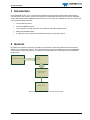
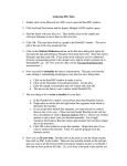
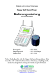
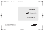
2 General
By means of an interface console commands are generated. These commands could be received as
RS232 or by network socket ports.. The commands are converted in PDS2000 to Sonar and PDS2000
control functions with their protocols. A Terminal command device is for this purpose in the PDS2000
project used.
PDS2000
Interface Console
RS232
Terminal
command
device driver
Network
protocol
7K data
Teledyne RESON 7K
Control Center
RESON 7K Sonar
Figure 2-1 Flow diagram Interface console with the sonar.
Terminal command device description
Page 3
Technical Bulletin
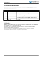
2.1 Protocol description
The command protocol, as generated by the console, can be seen as a proprietary NMEA sentence.
$TERMCMD,command*CS<CR><LF>
Field
Format
Description
1
$TERMCMD
Sentence identifier.
2
command
Actual command which will be mapped to a sonar, PDS2000 or
operating system command set.
This command is a ‘single’ ASCII character. See section
‘Commands’ on page 7.
3
CS
Calculated checksum according to NMEA standard. Refer to
Appendix A on page 19 for a description.
4
<CR><LF>
Terminator.
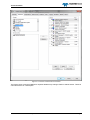
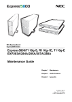
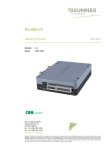
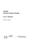
2.2 Device
Mapping of the received command to an external 7K, PDS2000 or operating system command ID can be
done directly in a serial IO keyboard command driver.
For PDS2000 in the device group ‘AUV Commands’ the device ‘Terminal Commands’ could be
selected.as the IO keyboard command driver.
The mapped command ID will be added and distributed with the AUV commands datablock.
Device selection is done in the vessel configuration’s equipment page.
Terminal command device description
Page 4
Technical Bulletin
Figure 2-2 Terminal Command device selection
The Device driver could be modified for required attribute map changes. Refer to below section ‘Terminal
command Driver’ for a description.
Terminal command device description
Page 5
Technical Bulletin
3 Terminal Command driver
Currently in PDS2000 the Terminal command driver is defined as.
Name: Terminal Commands[AUV].dev
[DefaultCom]
DefaultBaudrate = 9600
DefaultParity = 0
DefaultStopBits = 1
DefaultDataBits = 8
// -- string interface ---------------------------------[General]
SyncMode = 0
// Sync on terminator
SyncCount = 1
// Sync length
SyncString = 10
// Sync character is linefeed
DataRate = 10
// Maximum expected data rate 10 Hz
TimeOut = 0
// Maximum time out is 5 seconds
NumberOfMessages = 1
// Number of messages defined in this file
AlwaysNotify = 1
//$TERMCMD,A*4F<cr><lf>
// 0 1
[Msg(0)]
NmeaChecksum = 1
// Nmea Checksum must be valid
MsgMode = 0
// Input message
ID = $TERMCMD
// Message ID $TERMCMD
IDStart = 0
// start at char 0 ($TERMCMD)
IDLength = 8
// Id length 8 chacters
MessageType = 9
// Formula
NewElement = 1
// This message forwards the data block to the comps.
// command - internal number = function
// C
1 = stop sonar
// D
2 = shutdown computer
// J
3 = snapshot
// K
4 = show snapshot
// L
5 = gain
// M
6 = pulse length
// N
7 = range
// P
8 = power
// Q
9 = frequency
// R
10 = light mode
// A
// E
// F
// G
// H
-
20 = preset 1
21 = preset 2
22 = preset 3
23 = preset 4
24 = preset 5
// // +
-
40 = previous value
41 = next value
NumDataEntries = 1
NormData(0).Entry = 7
NormData(0).Formula = Value(Map("C,D,J,K,L,M,N,P,Q,R,A,E,F,G,H,,+","1,2,3,4,5,6,7,8,9,10,20,21,22,23,24,40,41",FindDel(",",1,FindDel("*",0,var0))))
Terminal command device description
Page 6
Technical Bulletin
[Attribs]
UserAttribs = 1
@tr.dev.LinkCompsFromDevice = 19, 1
LinkComps = 0
@tr.dev.preset.7kFrequency = 0x403, 1
// Frequency: 0 = 200 kHz, 1 = 400 kHz
@tr.dev.preset.7kRange = 0x403, 25
// Preset 1: Range 25 m
@tr.dev.preset.7kMaxPingRate = 0x403, 50
// maximum Ping rate = 0 - 50 p/s
@tr.dev.preset.7kPower = 0x403, 170
// Power = 170 - 205 dB
@tr.dev.preset.7kGain = 0x403, 40
// Gain = 0 - 83 dB
@tr.dev.preset.7kPulseLength = 0x403, 0.000033
// Pulse length = 0.000033 - 0.003 s
3.1 Commands
In the ‘Terminal command’ driver the following commands are defined with its checksum:
Command
Description
Checksum
C
Stop Sonar
2B
D
Shutdown the computer
2C
J
Take a snapshot
22
K
Show snapshot
23
L
Modify sonar Gain
24
M
Modify sonar pulse length
25
N
Modify sonar range
26
P
Modify sonar power
38
Q
Modify sonar frequency
39
R
Modify PDS2000 light mode
3A
A
Set sonar preset 1 values
29
E
Set sonar preset 2 values
2D
F
Set sonar preset 3 values
2E
G
Set sonar preset 4 values
2F
H
Set sonar preset 5 values
20
-
Decrement or previous value
45
+
Increment or next value
43
These commands must be received by the in section 2.1 defined protocol.
E.g. To stop the sonar the message $TERMCMD,C*2B<CR><LF> should be received. (With ‘C’ as the
Stop Sonar command)
For the modes; show snapshot, gain, pulse length, range, power, frequency and light mode the setting
could be changed after the mode is set with the ‘+’ or ‘-‘ command. See section ‘Operational example’ for
an example.
Terminal command device description
Page 7
Technical Bulletin
3.1.1 Preset
By above command (A, E,F,G or H) sonar preset values can be set. Sonar preset values are defined for:
Frequency
Range
Ping rate
Power
Gain
Pulse length
In the driver one preset values is defined. Up to five preset values could be added to the driver.
3.1.1.1 Adding Preset attribute values to driver
When additional to the defined preset 1 values, preset 2 values are required with for example a range of
50m and a ping rate of 40p/s this preset 2 values attributes are defined as below:
@tr.dev.preset(1).7kFrequency = 0x403, 1
@tr.dev.preset(1).7kRange = 0x403, 50
// Preset 2: Range 50 m
@tr.dev.preset(1).7kMaxPingRate = 0x403, 50
@tr.dev.preset(1).7kPower = 0x403, 175
@tr.dev.preset(1).7kGain = 0x403, 50
@tr.dev.preset(1).7kPulseLength = 0x403, 0.00006
These preset attribute values are attached to the driver below the preset 1 attribute values. Notice preset
1 values are listed in the driver as preset, preset 2 values as preset(1), preset 3 values as preset(2) etc.
With the command ‘E’ (as defined in the driver) the preset 2 values are set to the sonar.
$TERMCMD,E*2D<CR><LF>
3.1.2 Operational example
3.1.2.1 Gain
With the defined driver this means when for example the gain must be changed first the command ‘L’
must be send.
$TERMCMD, L*24<CR><LF>
When now command ‘+’ is send the gain could be increased.
$TERMCMD,+*43<CR><LF>
With the ‘-‘ command the gain is decreased.
$TERMCMD,-*45<CR><LF>
Terminal command device description
Page 8
Technical Bulletin
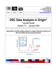
4 PDS2000
4.1 General
In PDS2000 a project should be defined, with the required devices such as the ‘Terminal commands’
device selected.
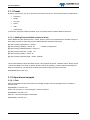
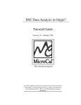
In the screen layout of this project the required views should be added as for example an Sonar Wedge
view in case a forward looker sonar is used.
Refer to the PDS2000 user manual for full details.
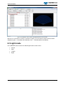
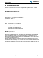
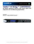
When the ‘Show snapshot’ command is received, automatically the snapshot view (maximized) is
displayed in the Acquisition screen layout.
Figure 4-1 PDS2000 Acquisition with Sonar Wedge view in normal operation mode
Terminal command device description
Page 9
Technical Bulletin
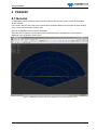
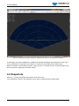
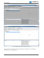
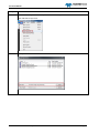
Figure 4-2 PDS2000 Acquisition switched to Snapshot view mode for showing all the snapshots
A subscription to the AUV datablocks is available and handled as attribute map changes as if they came
from the R7K Sonar Configuration View sliders or remote from the Seabat User Interface (SUI).
When for example a sonar setting as power, range, gain etc. is received from the console the slider in the
SUI or the Sonar configuration view also change.
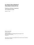
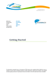
4.2 Snapshots
With the ‘J’ command snapshots will be taken of the sonar view.
The snapshots are saved in the PDS2000 control center’s multimedia JPG Images folder.
Terminal command device description
Page 10
Technical Bulletin
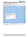
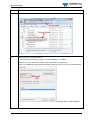
Figure 4-3 PDS2000 control Center with Multimedia tab and JPG folder.
When the ‘K’ command is received it is possible to display in the acquisition snapshot view the taken
snapshots by the ‘+’ command (next snapshot) or the ‘-‘ command (previous snapshot).
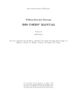
4.3 Light mode
In the PDS2000 Control center four different light modes could be used.
Normal
Night
Twilight
Bright
Terminal command device description
Page 11
Technical Bulletin
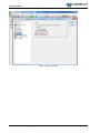
Figure 4-4 PDS2000 control Center with light mode ‘ twilight’
Figure 4-5 PDS2000 Control Center with light mode ‘normal’
The light mode could be changed by the terminal command ‘R’, followed by the ‘+’ (next) terminal
command or the ‘-‘ command (previous)
Terminal command device description
Page 12
Technical Bulletin
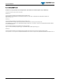
4.4 Alarm messages – Alerts view
When an alarm condition occur, an alarm message is generated in a automatically popped up Alerts view.
(For example when sensor data is not received)
Figure 4-6 Alarm Message
The user could disable the auto alert view to be popped up automatically in the PDS2000 project
configuration - options menu.
Terminal command device description
Page 13
Technical Bulletin
Figure 4-7 Auto show alerts
Terminal command device description
Page 14
Technical Bulletin
5 Auto start batch file
By means of a defined batch file it is possible to start automatically the RESON 7KCenter, the 7K I/O
module and PDS2000. Additionally a defined screen layout can be copied to a location and with the batch
file loaded. PDS2000 will start in this case with this defined screen layout.
5.1 Definition batch file
Timeout /t 10
Start”7kCenter” /D ”XXXX” /MIN “XXXX\7kcenter.exe”
Timeout /t 5
Start “IOModule” /D “YYYY” /MIN “YYYY\7kIOModule.bat”
Copy /A “VVVV” “WWWW” /Y
Timeout /t 5
Start”Acquisition” /D “ZZZZ” /MIN “ZZZZ\Master.exe” -A
With:
VVVV the location of the screen layout file
WWW project folder path with screen layout file
XXXX the path of the installed 7K version.
YYYY the path of the installed IOModule
ZZZZ the path of the installed PDS2000 version
5.2 Explanation
With the start commands: Start”7kCenter”, Start”IOModule” and Start”Acquisition” these applications are
started. The path were the exe files or batch files are located needs to be specified in the batch file..
With the timeout command a time delay is introduced to avoid an application is started up while the other
has not finished the startup sequence yet.
When the customer want to startup PDS2000 with a defined screen layout these screen layout needs to
be copied in the project. The batch file ‘Copy’ command is used for this purpose and the location were this
layout is saved and the current project folder needs to be specified.
The below table summarizes the procedure for creating a screen layout and to define this in the batch file.
Terminal command device description
Page 15
Technical Bulletin
Step
1
Action
Define a screen layout with the required views in the Acquisition.
Click File>Save Layout As…
2
Specify a name and click Save
Terminal command device description
Page 16
Technical Bulletin
Step
Action
3
The file will have the extension “.pcf”. Locate this file in the used PDS2000 Project folder.
4
Copy this file to a required location.
In the batch file the sentence: ‘Copy /A “VVVV” “WWWW” /Y’ is added
Specify the screen layouts file location path in the batch file. (field VVVV)
Click in the PDS2000 control Center File>Open project to have the current project path listed.
Specify also in the batch file the path of the current used PDS2000 project. (field WWWW)
Terminal command device description
Page 17
Technical Bulletin
5.3 EXAMPLE
A batch file could look like the example below. (Be aware the software path may be different)
rem adjust this timeout of 10 seconds to any delay
timeout /t 10
rem this should be modified to accommodate the latest installed version
start "7kCenter" /D "C:\PROGRAM FILES (x86)\RESON\7128(2013-11-08)" /MIN "C:\PROGRAM FILES (x86)\RESON\7128(2013-1108)\7kcenter.exe" -sim
timeout /t 5
rem this should be modified to accommodate the latest installed version
rem if the IO module is already in the startup menu either remove this part or remove from the startup menu
start "IOModule" /D "C:\Program Files (x86)\RESON\PDS2000 IO Module V3.7.0.14" /MIN "C:\Program Files (x86)\RESON\PDS2000 IO Module
V3.7.0.14\7kIOModule.bat"
rem this should be modified to accommodate the right place of the files
copy /A "C:\Users\erni\Desktop\L1[AcqComp].pcf" "D:\PDS2000 Projects\CABI\L1[AcqComp].pcf" /Y
timeout /t 5
rem this should be modified to accommodate the latest installed version (thus starting master.exe with the autostart option)
start "Acquisition" /D "C:\Program Files (x86)\RESON\PDS2000 V3.9.0.0" /MIN "C:\Program Files (x86)\RESON\PDS2000 V3.9.0.0\Master.exe" -A
Terminal command device description
Page 18
Technical Bulletin
Appendix A Checksum
Checksum is calculated by taking a logical exclusive-OR operation of the 8-bit message characters.
Checksum excludes the leading ‘$’, checksum delimiter ‘*’ and the checksum itself.
The following C-language routine calculates the checksum. Parameters are:
char* sz pointer to the string containing the message (excluding checksum).
int nCount number of characters in message (including leading ‘$’)
unsigned char Calc_checksum(char* sz, int nCount)
{
unsigned char cs; // Checksum
// Omit the $-character
for (i=1; i<Count; i++)
{
cs = cs ^((unsigned char)sz[i]);
}
return cs;
}
Notice that leading “$” is not included when calculating the checksum. Receiving application should
calculate the checksum of the message and compare it to the received checksum.
Terminal command device description
Page 19