1
Application Trailing Suction Hopper
PDS2000
Version 1.0.1
June 2010
RESON B.V.
Stuttgartstraat 42- 44
3047 AS Rotterdam
The Netherlands
Tel.: +31 (0)10 245 15 00
www.reson.nl
Amendment Record Sheet
Rev.
Date
Reason for Modifications
1.0.1
10/06/2010
New RESON logo added.
1.0
20/06/2007
First version of the Application Trailing Suction Hopper Manual. This is a
draft version of the manual.
Contents
1 Introduction
1
1.1 Trailing Suction Hopper .......................................................................................... 1
2 Setup a New Project
3
2.1 Introduction............................................................................................................. 3
2.2 Start a New Project................................................................................................. 3
2.2.1 New Project Wizard ...................................................................................... 3
2.2.2 Geodesy........................................................................................................ 4
2.2.3 Vessel ........................................................................................................... 4
2.2.4 Configuration................................................................................................. 4
3 Vessel Configuration
5
3.1 Introduction............................................................................................................. 5
3.2 Geometry ................................................................................................................ 5
3.2.1 Bend.............................................................................................................. 6
3.2.2 Upper Pipe .................................................................................................... 6
3.2.3 Lower Pipe .................................................................................................... 7
3.2.4 Suction Head ................................................................................................ 7
3.2.5 Settings of the Geometry Page..................................................................... 7
3.3 Equipment .............................................................................................................. 8
3.3.1 Compass ....................................................................................................... 9
3.3.2 Depth Sensor ................................................................................................ 9
3.3.3 Dredge Positioning System......................................................................... 10
3.3.4 Dredge Production ...................................................................................... 10
3.3.5 Dredge Status ............................................................................................. 10
3.3.6 Load and Draught ....................................................................................... 10
3.3.7 Positioning System Geogs.......................................................................... 11
3.3.8 Tide Gauge ................................................................................................. 12
3.3.9 Trip Info ....................................................................................................... 12
3.3.10 VRU........................................................................................................... 12
3.4 Computations ....................................................................................................... 13
3.4.1 Advanced Computations............................................................................. 13
3.5 Data Sources........................................................................................................ 14
3.6 Guidance .............................................................................................................. 14
3.7 Tools ..................................................................................................................... 15
3.7.1 Production Parameters ............................................................................... 15
PDS2000 - Application Trailing Suction Hopper
Contents • i
3.7.2 Trip Registration ......................................................................................... 16
3.7.3 Pipe Configuration ...................................................................................... 17
3.8 Logging ................................................................................................................ 19
3.8.1 PDS2000 Grid Model.................................................................................. 19
3.8.2 Production Format ...................................................................................... 19
3.8.3 Dredge Track Format ................................................................................. 20
4 Calibration
21
4.1 Introduction .......................................................................................................... 21
4.2 Suction Tube Calibration...................................................................................... 21
4.2.1 Upper Pipe – Horizontal Angle ................................................................... 22
4.2.1.1 Horizontal angle with pipe in cradle .................................................. 22
4.2.2 Upper Pipe – Vertical Angel ....................................................................... 22
4.2.2.1 Pipe on Water Line ........................................................................... 22
4.2.2.2 Vertical Angle with Pipe in Cradle Relative Vessel........................... 23
4.2.3 Lower Pipe – Horizontal Angle ................................................................... 24
4.2.3.1 Horizontal angle with pipe in cradle .................................................. 24
4.2.4 Lower Pipe – Vertical Angel ....................................................................... 24
4.2.4.1 Pipe on Water Line ........................................................................... 24
4.2.4.2 Vertical Angle with Pipe in Cradle Relative Vessel........................... 25
5 Acquisition
27
5.1 Introduction .......................................................................................................... 27
5.1.1 Realtime ..................................................................................................... 27
5.1.2 Logging ....................................................................................................... 27
5.2 Layouts................................................................................................................. 28
5.3 Menu Bar and Toolbar ......................................................................................... 29
6 Views
31
6.1 Introduction .......................................................................................................... 31
6.2 Plan View – General Dredge Operation............................................................... 32
6.2.1 Plan View Toolbar ...................................................................................... 32
6.2.2 Plan View Properties .................................................................................. 35
6.2.3 Plan View Layers........................................................................................ 36
6.2.4 Coverage Settings ...................................................................................... 37
6.3 3D View – Online Dredge .................................................................................... 38
6.3.1 3D View Toolbar ......................................................................................... 38
6.3.2 3D View Properties..................................................................................... 40
6.3.3 3D View Layers .......................................................................................... 41
6.4 Profile – Realtime Design..................................................................................... 42
6.4.1 Profile Toolbar ............................................................................................ 42
6.4.2 Profile Properties ........................................................................................ 43
6.4.3 Profile Layers.............................................................................................. 44
6.4.3.1 Graphics of the Profile ...................................................................... 44
ii • Contents
PDS2000 - Application Trailing Suction Hopper
6.4.3.2 Left Panel of the Profile ..................................................................... 45
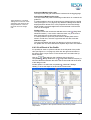
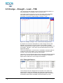
6.5 Dredge – Draught – Load – TDS.......................................................................... 46
6.5.1 Draught Sensor........................................................................................... 46
6.5.2 Hopper Sensor............................................................................................ 47
6.5.3 Load ............................................................................................................ 47
6.5.4 TDS ............................................................................................................. 48
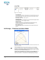
6.6 Dredge – Flow/Concentration Meter .................................................................... 48
6.7 Numerics............................................................................................................... 49
PDS2000 - Application Trailing Suction Hopper
Contents • iii
Figures
Figure 3-1
Top and right view of a bend on starboard side...................................................................6
Figure 3-2
Top and right view of the upper pipe ...................................................................................6
Figure 3-3
Top and right view of the lower pipe ....................................................................................7
Figure 3-4
Top and right view of the suction head ................................................................................7
Figure 3-5
The Equipment page............................................................................................................8
Figure 3-6
The Computations page.................................................................................................... 13
Figure 3-7
The Advanced Computations page................................................................................... 13
Figure 3-8
The Data Sources page with three Sealevel computations.............................................. 14
Figure 3-9
Production parameters page in the Tools page................................................................ 15
Figure 3-10
Trip Registration page in the Tools page.......................................................................... 16
Figure 3-11
Pipe Configuration page in the Tools page....................................................................... 17
Figure 3-12
The offsets of the bend ..................................................................................................... 17
Figure 3-13
The Y offset of the upper pipe........................................................................................... 18
Figure 3-14
The Y offset of the lower pipe ........................................................................................... 18
Figure 3-15
The offsets of the suction head......................................................................................... 18
Figure 3-16
The Logging page ............................................................................................................. 19
Figure 4-1
Top view of the horizontal angle with the upper pipe in the cradle................................... 22
Figure 4-2
Side view of the vertical angle with the upper pipe on the water line ............................... 22
Figure 4-3
Side view of the vertical angle with the upper pipe in the cradle ...................................... 23
Figure 4-4
Top view of the horizontal angle with the lower pipe in the cradle ................................... 24
Figure 4-5
Side view of the vertical angle with the lower pipe on the water line................................ 24
Figure 4-6
Side view of the vertical angle with the lower pipe in the cradle....................................... 25
Figure 5–1
The Displays window to add, to switch on/off, to remove or to rename views ................. 28
Figure 5–2
Add Display dialog to add a view ...................................................................................... 28
Figure 5–3
Add Display in the context menu ...................................................................................... 29
Figure 6-1
Plan View – General Dredge Operation view with orientation mode ‘North Up’............... 32
Figure 6-2
Measure window ............................................................................................................... 33
Figure 6-3
Plan View with orientation mode Heading Up (left) and Fixed Skew (right) ..................... 34
Figure 6-4
The Properties of the Plan View – General Dredge Operation view ................................ 35
Figure 6-5
The Layers of the Plan View – General Dredge Operation view ...................................... 36
Figure 6-6
The Coverage Settings for the plan view.......................................................................... 37
Figure 6-7
The 3D View – Online Dredge with the 3D studio models of the hopper and the
suction tube....................................................................................................................... 38
Figure 6-8
Measure window in 3D view ............................................................................................. 39
Figure 6-9
The Properties of the 3D View – Online Dredge............................................................... 40
Figure 6-10
The Layers of the 3D View – Online Dredge .................................................................... 41
Figure 6-11
Profile – Realtime Design view with a right view of the vessel, a starboard suction
tube, an active grid model and a design model ................................................................ 42
iv • Figures
PDS2000 - Application Trailing Suction Hopper
Figure 6-12
The Properties of the Profile – Realtime Design view....................................................... 43
Figure 6-13
The Layers of the Profile – Realtime Design view ............................................................ 44
Figure 6-14
Properties of the Up Down Indicator with the two possible computations ........................ 45
Figure 6-15
Dredge – Draught – Load – TDS view with 4 draught sensors......................................... 46
Figure 6-16
The draught sensors with their residuals .......................................................................... 46
Figure 6-17
Hopper sensors with their residuals .................................................................................. 47
Figure 6-18
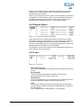
Load page.......................................................................................................................... 47
Figure 6-19
TDS page .......................................................................................................................... 48
Figure 6-20
Dredge – Flow/Concentration Meter view with the information of the starboard
suction tube ....................................................................................................................... 48
Figure 6-21
Numerics view ................................................................................................................... 49
Figure 6-22
Numerics page configuration to select data for the Numerics view .................................. 49
PDS2000 - Application Trailing Suction Hopper
Figures • v
1 Introduction
1.1 Trailing Suction Hopper
The application type ‘Trailing Suction Hopper’ is for a project where a
suction hopper is used for dredging.
In this application manual the setup of a trailing suction hopper project will
be discussed. For the standard information of PDS2000 will be referred to
the PDS2000 User Manual.
After the project is setup the separate tools of the trailing suction hopper
configuration have to be calibrated. The calibrations of the upper pipe and
lower pipe will be explained in a separate chapter of the manual.
The last chapters in this manual will discuss the Acquisition and the most
used views in the Acquisition.
This manual is also available as a HTML Help file. Press F1 or select
Help > Help Topics to open the PDS2000 help files.
PDS2000 - Application Trailing Suction Hopper
Introduction • 1
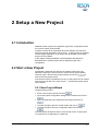
2 Setup a New Project
2.1 Introduction
PDS2000 needs a project, an application type and a configuration before
any of the modules can be started.
A project contains all the information about the settings, the method of
surveying and the information to do a survey. To get a project for a trailing
suction hopper application, a new project can be created or an existing
project can be modified.
In the chapter ‘Starting PDS2000’ of the PDS2000 User Manual is
described how to setup a project with an application type and a
configuration.
2.2 Start a New Project
If PDS2000 is started for the first time an existing project has to be
selected to start up the Control Center. If there is no project available,
check the option ‘Run the New Project Wizard’ and click on
to
start up the new project wizard.
If the Control Center in PDS2000 is running, a new project can be created
from the menu bar with File > New Project…. and the new project wizard
will be started.
2.2.1 New Project Wizard
Create an empty project:
Enter a new project name and click on
.
Ignore the project configuration settings for the moment and click on
.
Select as application type Trailing Suction Hopper and click on
.
Uncheck the option ‘Run the vessel wizard’ and click on
.
Uncheck the option ‘Run the configuration wizard’ and click on
.
The new project will become active in the Control Center. In this project
no vessel and no configuration is created yet.
PDS2000 - Application Trailing Suction Hopper
Setup a New Project • 3
2.2.2 Geodesy
In PDS2000 a coordinate system has to be selected.
Select Edit > Project Configuration from the menu bar or click on
in the
toolbar to open the project configuration to select or create a coordinate
system for the project. Select in the Project Configuration window the
Coordinate System and select one of the existing coordinate systems or
create a new coordinate system with
.
See for a detailed explanation of the coordinate system the chapter
‘Coordinate System’ in the PDS2000 User Manual.
See for a detailed explanation
of the Geo Calculator the
chapter ‘Control Center – Geo
Calculator’ of the PDS2000
User Manual.
If a coordinate system is selected or created, the coordinate system can
be checked in the Geo Calculator. Select Tools > Geo Calculator from the
menu bar and add coordinates for the satellite ellipsoid, the local ellipsoid
or the projection.
2.2.3 Vessel
In PDS2000 the ship with the dredge equipment is called a vessel.
Select Acquisition > New > Vessel… from the menu bar of the Control
Center an give a name for the vessel that has to be created. Click on
and the vessel wizard will be started with the Geometry page.
the other pages of the vessel configuration can be opened.
With
Another way to create a new vessel is by selecting the tab Project in the
Explorer of the Control Center. Click with the right mouse button on
Vessel in the Explorer and select the option ‘New File’ to create a new
vessel and the vessel configuration window with tabs for the Geometry,
Equipment, Computations, Data Sources, Guidance, Tools, Logging,
Simulation, Aliases and Alarms will be opened.
See the chapter ‘Vessel Configuration’ on page 5 for a detailed setup of
the vessel configuration for a trailing suction hopper application.
2.2.4 Configuration
If the vessel is setup, a new configuration has to be created before the
Acquisition of PDS2000 can be opened.
Select Acquisition > New > Configuration… from the menu bar of the
Control Center and give a name for the configuration that has to be
and the configuration wizard will be started with
created. Click on
the other pages of the configuration can
the Vessels page. With
be opened.
In the tab Vessels, click under ‘Local’ on
vessel configuration.
to add the just created
Another way to create a new configuration is by selecting the tab Project
in the Explorer of the Control Center. Click with the right mouse button on
Configuration in the Explorer and select the option ‘New File’ to create a
new configuration and the configuration window with the tabs will be
opened.
4 • Setup a New Project
PDS2000 - Application Trailing Suction Hopper
3 Vessel Configuration
3.1 Introduction
The vessel configuration contains al the settings necessary for the
measurements and the displays of the dredging work.
The general information about the vessel configuration is explained in the
chapter ‘Vessel Configuration’ of the PDS2000 User Manual.
In this chapter the specific settings are explained to setup the Trailing
Suction Hopper application.
3.2 Geometry
In this page the contours of the vessel and the suction tube(s) has to be
drawn. These contours can be drawn in 2D or in 3D - wireframe. The 2D
drawings are created under the item ‘Vessel contour’ and the 3D –
wireframes are 3D DXF files.
For the 2D contours a top view and at least one side view have to be
drawn. The side views of all the contours should be from the same side,
so the vessel with the suction tube(s) can be displayed in a Profile –
Realtime Design view in the Acquisition (see page 42).
The suction tube of a trailing suction hopper dredger has to be drawn in
segments, because each part of the pipe can be moved separately. The
suction tube exists of a bend, an upper pipe, a lower pipe and a suction
head.
Two suction tubes can not be displayed in one Profile – Realtime Design
view. So draw for one suction tube a left side and for one a right side and
open two profile views in the Acquisition.
PDS2000 - Application Trailing Suction Hopper
Vessel Configuration • 5
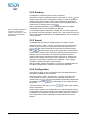
3.2.1 Bend
The (0, 0, 0) of the drawing of the bend should be the centre of the
connection with the upper pipe, as shown below.
+Y
+Z
+Y
+X
Connection Point with the Upper Pipe
(0, 0, 0)
Figure 3-1
Top and right view of a bend on starboard side
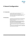
3.2.2 Upper Pipe
The (0, 0, 0) of the drawing of the upper pipe should be the centre of the
connection with the lower pipe, as shown below.
+Y
Connection Point with the Bend
+Z
+Y
+X
Connection Point with the Lower Pipe
(0, 0, 0)
Figure 3-2
6 • Vessel Configuration
Top and right view of the upper pipe
PDS2000 - Application Trailing Suction Hopper
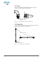
3.2.3 Lower Pipe
The (0, 0, 0) of the drawing of the lower pipe should be the centre of the
connection with the suction head, as shown below.
+Y
Connection Point with the Upper Pipe
+Z
+Y
+X
Connection Point with the Suction Head
(0, 0, 0)
Figure 3-3
Top and right view of the lower pipe
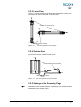
3.2.4 Suction Head
The (0, 0, 0) of the drawing of the suction head should be the centre and
the end of the suction head, as shown below.
+Y
Connection Point with the Lower Pipe
+Z
+X
+Y
End of the Suction Head
(0, 0, 0)
Figure 3-4
Top and right view of the suction head
3.2.5 Settings of the Geometry Page
(
After all the contours are drawn in the ‘Vessel contour’ or are available as
wireframes in the ‘Vessel wireframe’, the drawing of the vessel should be
selected as active vessel contour.
PDS2000 - Application Trailing Suction Hopper
Vessel Configuration • 7
The offsets, which are needed on the vessel, have to be added to the
offset table in the Geometry page.
Antenna offset of a positioning system.
The inlet location(s); the location(s) on the vessel where the suction
tube(s) is/are connected to the vessel.
The draught locations.
The level locations.
The Zero offset correspond to the (0, 0, 0) as is used in the vessel
drawing.
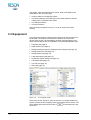
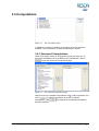
3.3 Equipment
In the Equipment page the sensors which are used on the vessel have to
be selected. The sensors that will be discussed are the most used
devices from the list. It is still possible, because of dongle settings, that
some of these devices are not available for the selected application type.
Compass (see page 9)
Depth Sensor (see page 9)
Dredge Positioning System (Trailing Suction Hopper) (see page 10)
Dredge Production (see page 10)
Dredge Status (see page 10)
Load and Draught (see page 10)
Positioning System Geogs (see page 11)
Tide Gauge (see page 12)
Trip Info (see page 12)
VRU (see page 12)
Figure 3-5
The Equipment page
Select from the list ‘Groups’ a group of devices, e.g. Dredge Positioning
System (Trailing Suction Hopper). Select from the list ‘Device drivers’ one
of the dredge-pos-tsh drivers and click on
to add the driver to the
device list.
8 • Vessel Configuration
PDS2000 - Application Trailing Suction Hopper
For more information about
the interfacing, see chapter
‘Control Center –
Interfacing’ in the PDS2000
User Manual.
(
If a device driver is added to the device list in the Equipment page, the
communication port has to be selected. Click on
to open the
interface page where the communication port can be added, modified or
selected. If the communication port is set and the sensor is connected to
PDS2000, click on
to test the communication with the sensor.
For most of the items in the properties the default settings can be used.
Below only the essential settings in the properties of the sensors will be
discussed.
3.3.1 Compass
On the vessel the compass is used to get a heading of the vessel.
In the first properties window (‘
Compass’):
Heading Correction
This should be the correction derived from the compass calibration.
3.3.2 Depth Sensor
On the vessel the depth sensor will be used to measure the draught of the
vessel.
In PDS2000 the depth (draught) sensor is used in the sea level
computation to obtain the sea level and will be used for the load
computation in the Load and Draught (see page 10).
(
(
By default the sea level value entered in the Geometry page will be used
for the sea level computation. To make the sea level computation from
the depth sensor the primary computation, select the sea level
computation from the depth sensor as primary in the Data Sources (see
page 14). Preferable is to select the depth sensor which is closest to the
positioning system.
In the first properties window (‘
Depth sensor’):
Device Offset
Select the offset of the depth sensor from the list. The offset has to be
created in the Geometry page.
Time Delay
Enter the delay in the output from the depth sensor. The time delay is
always ≥ 0 sec.
In the second properties window (‘
Sealevel Computation’):
Integration Period (only for depth sensors with a depth as output)
Enter a value for the integration period over which the depth is
calculated.
Approx. Latitude Mode (only for pressure sensors)
Select a manual input or latitude from the position.
Approx. Latitude (only for pressure sensors)
Enter the latitude if the mode is set on manual.
Atmospheric Pressure Correction (only for pressure sensors)
Select Enabled if an atmospheric pressure correction is necessary.
Atmospheric Pressure (only for pressure sensors)
Enter the atmospheric pressure correction if this is necessary.
PDS2000 - Application Trailing Suction Hopper
Vessel Configuration • 9
3.3.3 Dredge Positioning System
This device driver reads the data from the sensors on the suction tube(s)
to calculate the position and the height (depth) of the origin (0, 0, 0) of the
suction head.
For this application it is possible to select two times a dredge positioning
system, one on port side and one on starboard side of the vessel.
In the first properties window (‘
Suction Hopper)’):
Dredge Positioning System (Trailing
Device Offset
This is the offset of the inlet location where the bend of the suction
tube is connected to the vessel. The offset should be defined in the
Geometry page.
Pipe Diameter
This is the pipe diameter of the suction tube and will be used in the
calculation of the dredge production.
All other items in the first properties window can be set in the Production
parameters page of the Tools page (see page 15) or are derived from the
Tools Calibration in the Acquisition (see page 21).
In the second properties window (‘ Drag-head Relative Position’) and
the third properties window (‘ Drag-head Absolute Position’) the defaults
settings can be used.
(
In the third properties window the option ‘Grid Model Update Mode’ is set
on Volume Update to give the best update of the active grid model.
3.3.4 Dredge Production
With this device the flow and concentration of the dredge material can be
measured (see page 48). For calculating the dredge production the water
density and the product density has to be known. The water density and
the product density can be set in the Production Parameters page of the
Tools page (see page 15).
The default settings in the properties window (‘
be used.
Dredge Production’) can
3.3.5 Dredge Status
With this device the status of the dredging can be monitored. The dredge
status can be relevant for the start and end of the trip registration (see
page 16).
There are no settings in the properties window (‘
can be set.
Dredge Status’) that
3.3.6 Load and Draught
This device will read in the draught sensors and, if available, the level
sensors to measure the level in the bunker(s).
In the first properties window (‘
Load and Draught’):
Draught Sensor Offset
Select the offset of one the draught sensors (depth sensors) from the
list. This offset has to be defined in the Geometry page.
Draught Correction
Specify the correction for the above selected draught sensor.
10 • Vessel Configuration
PDS2000 - Application Trailing Suction Hopper
Level Sensor Offset
Select the offset of one the level sensors from the list. This offset has
to be defined in the Geometry page.
Level Correction
Specify the correction for the above selected level sensor.
The number of draught sensors and level sensors in the properties
window will depend on the selected device driver.
(
If only 2 draught sensors are used for the load and draught computation
then is advisable to place the two draught sensors in the middle of the
vessel.
In the second properties window (‘
settings can be used.
Load and Draught’) the defaults
3.3.7 Positioning System Geogs
This sensor gives a position derived from several GPS satellites.
In the first properties window (‘
Positioning System Geogs’):
Device Offset
Select the offset of the GPS antenna from the list. This offset has to be
defined in the Geometry page.
Time Delay
If known, enter the delay in the output from the positioning system.
The time delay is always ≥ 0 sec.
Datum Transformation
The position from the positioning system is in most cases a WGS’84 or
ETRS’89 position. To recalculate the position to a local position the
relevant datum transformation has to be selected. There are three
options: Use other datum transformation, Use project coordinate
system and Use no datum transformation.
When a different datum transformation is selected, an extra option
appears in the properties called Datum Transformation. Select in
this new option the right datum transformation for the positioning
system.
When project coordinate system is selected, the datum
transformation as specified in the coordinate system will be used.
When no datum transformation is selected, the coordinates of the
positioning system will not be recalculated to a local position; they
stay in the coordinates as received from the positioning system.
In the second properties window (‘
nothing can be selected.
In the third properties window (‘
(
If no standard deviation is
received, the height standard
deviation mask has to be
0.05m.
Antenna Position from Geogs’)
Reference Point Computation’):
Height Source
Select for the computation of the height related to the received position
the Z of the GPS RTK system or the tidal information from tide gauges
or predicted tides.
PDS2000 needs a chart datum to calculate the depth of the suction
head, so use always RTK or tidal information.
Height Standard Deviation Mask
Enter a maximum value for the standard deviation of the RTK Z to
accept the RTK Z for the height computation. If the standard deviation
is more than the maximum value the height computation becomes
‘Height Held’. Only valid if ‘Height Source’ is set on GPS Height (RTZ).
PDS2000 - Application Trailing Suction Hopper
Vessel Configuration • 11
3.3.8 Tide Gauge
In stead of using GPS RTK as height source, one or more tide gauges
can be used in combination with the depth sensor to calculate the
absolute height or depth of the vessel.
The tide station(s) has to
be setup in the Explorer
(see the chapter ‘Explorer
– Tide Station’ in the
PDS2000 User Manual).
In the properties window (‘
Tide gauge’):
Tide Stations
Select at the bottom of the properties window the tide station(s) that
are related to the tide gauge driver.
With some of the device drivers tide data of more than one tide station
can be collected at the same time. Select in that case in the properties
window the relevant tide stations. Other device drivers are only for one
tide station; select then only one tide station in the properties window.
If more than one tide station is used and the device driver is only for one
tide station, select the device driver multiple times until all the tide stations
are selected.
(
(
An advanced computation has to be created in the Computations after the
tide gauge is setup (see page 13).
Also in the properties of the positioning system (in the ‘ Reference Point
Computation’) the ‘Height Source’ has to be set to Tide (see page 11).
3.3.9 Trip Info
This device can be used to change the trip number. And if in the trip
registration (see page 16) the option When trip number changes is
selected the new trip will be started.
There are no settings in the properties window (‘
set.
Trip Info’) that can be
3.3.10 VRU
A VRU is used to measure the attitude (roll, pitch and heave) of the
vessel.
In the first properties window (‘
VRU’):
Time Delay
Enter the delay in the output from the VRU. The time delay is always ≥
0 sec.
Device Offset
If only the roll and pitch of the VRU are used, no device offset has to
be selected. If the heave is used then a device offset is necessary and
the offset should be defined in the Geometry page.
Roll / Pitch Correction
A roll and pitch correction, derived from the VRU calibration, can be
entered in the properties. Check the sign convention of the roll and
pitch before entering the values.
In the second properties window (‘ Attitude computation’) the default
settings can be used.
12 • Vessel Configuration
PDS2000 - Application Trailing Suction Hopper
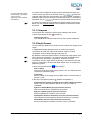
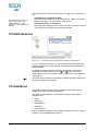
3.4 Computations
Figure 3-6
The Computations page
In PDS2000 a number of standard computations as shown above are
available. The user influence on these computations is limited.
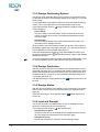
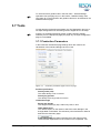
3.4.1 Advanced Computations
When a tide gauge is setup in the Equipment page (see page 12), an
advanced computation has to be added to the computations. Click on
to open the Advanced Computations page.
Figure 3-7
The Advanced Computations page
Select from the list ‘Available computations’ the ‘ Tide Computation’ and
click on
to add the computation to the list of ‘Defined
computations’. With
the properties of the selected computation
becomes available.
PDS2000 - Application Trailing Suction Hopper
Vessel Configuration • 13
The relevant items in the properties window of the ‘
are:
Tide Computation’
Tide Reduction Computation Mode
Select one of the modes for the tide computation; Single Tide Station,
Multiple Tide Station or Tide Stations Along Route.
The tide station(s) has to be
setup in the Explorer (see
chapter ‘Explorer – Tide
Stations’ in the PDS2000 User
Manual).
Tide Station Name / Tide Stations
Select the tide station(s) that are used for the tide computation with the
above selected ‘Tide Reduction Computation Mode’.
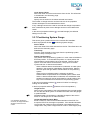
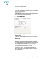
3.5 Data Sources
Figure 3-8
The Data Sources page with three Sealevel computations
If one or more depth sensors or a Load and Draught are selected in the
Equipment page, then for the Sealevel computation more computations
will be available.
By default the Sealevel (Reference point) computation is the primary
computation. Change with the arrows (
and
) the order of the
computations. The first computation will be used as the primary Sealevel
computation.
(
The depth sensor closest to the positioning system should be selected for
the primary Sealevel computation.
3.6 Guidance
The guidance will be used to guide the dredger. It will depend on the
dongle which guidance types are available.
The guidance types that can be available for trailing suction hopper
application are:
Route
Waypoints
Design Model
Work Area
Restricted Area
See for a detailed explanation of the different guidance types the chapter
‘Guidance’ in the PDS2000 User Manual.
14 • Vessel Configuration
PDS2000 - Application Trailing Suction Hopper
(
To use and show a guidance file in the Plan View – General Dredge
Operation view (see page 32) or in the Profile – Realtime Design view
(see page 42) in the Acquisition the guidance file has to be selected in the
related Guidance page.
3.7 Tools
On this page the Production parameters, the Trip Registration and one or
two Pipe Configurations for the trailing suction hopper have to be setup.
(
If there is no ‘Dredge Positioning System (Trailing Suction Hopper)’
selected yet in the Equipment page (see page 10), the Pipe Configuration
page is not available.
3.7.1 Production Parameters
In the Production Parameters page settings which are used for the
calculations of the load and draught have to be set.
Figure 3-9
Production parameters page in the Tools page
Product specification
Density water (situ)
The water density in situ in tons/m³.
Density dry product
The density of the dry product in tons/m³.
Load and draught
Empty ship weight
The weight of the empty ship, without any load, in tons.
Table datum point
The reference point on the vessel to which the mean draught in the
draught table is calculated. The reference point should be an offset as
defined in the Geometry page.
In the draught table the relation between the mean draught of the
vessel and the displacement of the vessel in tons is specified. The
PDS2000 - Application Trailing Suction Hopper
Vessel Configuration • 15
mean draught is corrected for the density of the water in situ and for
the offsets of the draught sensors.
Tons dry solids
Table datum point
The reference point on the vessel to which the mean level in the
hopper table is calculated. The reference point should be an offset as
defined in the Geometry page.
In the hopper table the relation between the mean level in the bunkers
and the volume in the bunkers in m³ is specified.
3.7.2 Trip Registration
Figure 3-10
Trip Registration page in the Tools page
Start trip number
A trip number can be entered. The trip number will be part of the log
data file name.
Start new trip
Three options are available to start a new trip.
Manually. With the menu option Start Next Trip in the Tools menu of
the Acquisition the user can start the next trip.
When dredge status changes. Select the dredge statuses when the
next trip has to be started. In the example above the next trip will start
when the dredge status is changed from Dredging to Dumping.
When trip number changes. There are two options to change the trip
number; in the Trip Registration page of the Tools Settings in the Tools
menu of the Acquisition and with the trip info device.
Generate report at end of trip
If this options is checked, a plot will be generated according the
selected plot template. The logged data file of the trip will be used to
plot the dredge tracks.
16 • Vessel Configuration
PDS2000 - Application Trailing Suction Hopper
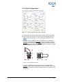
3.7.3 Pipe Configuration
Figure 3-11
Pipe Configuration page in the Tools page
For each suction tube on the trailing suction hopper a pipe configuration
has to be setup. The procedure to fill in the Pipe Configuration page is:
Select a pipe configuration or create a new pipe configuration with
.
Fill in the X and Y offset (P1 and P2) for the bend. For a starboard
bend the X offset should be negative and for a port bend it should be
positive. The Y offset is always negative. Select how the bend has to
be presented in the views, a shape or a wireframe, and select the right
shape or wireframe for the bend.
P2
P1
P2
Figure 3-12 The offsets of the bend
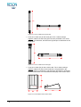
Fill in the Y offset (P3) for the upper pipe. The Y offset is always
negative. Select how the upper pipe has to be presented in the views,
a shape or a wireframe, and select the right shape or wireframe for the
upper pipe.
PDS2000 - Application Trailing Suction Hopper
Vessel Configuration • 17
P3
P3
Figure 3-13 The Y offset of the upper pipe
Fill in the Y offset (P4) for the lower pipe. The Y offset is always
negative. Select how the lower pipe has to be presented in the views,
a shape or a wireframe, and select the right shape or wireframe for the
lower pipe.
P4
P4
Figure 3-14 The Y offset of the lower pipe
Fill in the Y offset (P5) for the suction head. The Y offset is always
negative. Select how the suction head has to be presented in the
views, a shape or a wireframe, and select the right shape or wireframe
for the suction head. Fill in the effective width (P6) of the suction head.
P5
P5
P6
Figure 3-15 The offsets of the suction head
18 • Vessel Configuration
PDS2000 - Application Trailing Suction Hopper
3.8 Logging
Figure 3-16
The Logging page
In the chapter ‘Vessel Configuration - Logging’ of the PDS2000 User
Manual the options of the right side in the Logging page will be explained.
3.8.1 PDS2000 Grid Model
The PDS2000 Grid Model file format is used in the Acquisition to build up
an on-line depth model during the work activities and can also be used as
an on-line coverage.
If a PDS2000 Grid Model has to be used, check the option and some
extra information will appear in the Logging page (see Figure 3-16
above).
Select the grid model file name. If a new file has to be created, click on
, give a new file name and click on
in the file dialog. Select in
the grid model setup one or more data types for the grid model and enter
a cell size.
(
If the cell size is too small the update of the grid model takes too much
time and if it is too big it looks like nothing is taken away in one go with
the suction head.
The grid model will be filled with the information from the added device
data in ‘Data for grid model logging’. For two suction tubes two devices
have to be selected, for each suction tube one.
3.8.2 Production Format
In the Acquisition the production of the suction tube(s) can be displayed
with a grid model. The grid model is will show the production data from
the device driver ‘Dredge Production’ (see page 10). For two suction
tubes two devices have to be selected, for each suction tube one.
To create a grid model with the production the same procedure as for the
PDS2000 Grid Model has to be followed (see above).
PDS2000 - Application Trailing Suction Hopper
Vessel Configuration • 19
3.8.3 Dredge Track Format
The calculated position of the suction head(s) will be logged. For this log
file a sampling rate has to be specified, because it is not necessary to log
all the suction head(s) positions. The log file is used as an indication for
the dredge positions.
20 • Vessel Configuration
PDS2000 - Application Trailing Suction Hopper
4 Calibration
4.1 Introduction
For the trailing suction hopper application one or two suction tube
calibrations are available.
Before the calibration can be started all other equipment on the vessel
has to be installed and calibrated. PDS2000 should be running and a
project should be setup correctly.
The calibration will take place in the Acquisition which can be started by
clicking on
.
The calibration of the suction tube(s) will take place in the Tools
Calibration, which can be opened with Tools > Tools Calibration from the
menu bar of the Acquisition.
4.2 Suction Tube Calibration
The suction tube calibration contains a horizontal and a vertical angle
calibration of the upper and lower pipe.
At the moment is for the horizontal angel calibration only one calibration
method available and for the vertical angle calibration two different
methods.
PDS2000 - Application Trailing Suction Hopper
Calibration • 21
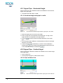
4.2.1 Upper Pipe – Horizontal Angle
At the moment only one calibration method is available for the horizontal
angle of the upper pipe:
Horizontal angle with pipe in cradle
4.2.1.1 Horizontal angle with pipe in cradle
Figure 4-1
Top view of the horizontal angle with the upper pipe in the cradle
1. Place the upper pipe is on deck in the cradle.
2. Enter as ‘Set point’ the measured horizontal angle. The sign of the
angle should be as explained in the figure above.
3. Click on
pipe.
to start the horizontal angle calibration of the upper
4. The horizontal angle calibration is finished after the value in the angle
offset box is changed.
5. Continue with the other calibrations or close the Tools Calibration
window with
. The angle offset will only be accepted when the
Tools Calibration window is closed with
.
4.2.2 Upper Pipe – Vertical Angel
At the moment two calibration methods are available for the vertical angle
of the upper pipe:
Pipe on water line
Vertical angle with pipe in cradle relative vessel
4.2.2.1 Pipe on Water Line
Figure 4-2
22 • Calibration
Side view of the vertical angle with the upper pipe on the water line
PDS2000 - Application Trailing Suction Hopper
1. Select the calibration method ‘Pipe on water line’.
2. Place the upper pipe horizontal, the best way to do this is by placing
the upper pipe on the water line.
3. No ‘Set point’ has to be entered.
4. Click on
to start the vertical angle calibration of the upper pipe.
5. The vertical angle calibration is finished after the value in the angle
offset box is changed.
6. Continue with the other calibrations or close the Tools Calibration
window with
. The angle offset will only be accepted when the
Tools Calibration window is closed with
.
4.2.2.2 Vertical Angle with Pipe in Cradle Relative Vessel
Figure 4-3
Side view of the vertical angle with the upper pipe in the cradle
1. Select the calibration method ‘Vertical angle with pipe in cradle relative
vessel’.
2. Place the upper pipe is on deck in the cradle.
3. Enter as ‘Set point’ the measured vertical angle. The sign of the angle
should be as explained in the figure above.
4. Click on
to start the vertical angle calibration of the upper pipe.
5. The vertical angle calibration is finished after the value in the angle
offset box is changed.
6. Continue with the other calibrations or close the Tools Calibration
window with
. The angle offset will only be accepted when the
Tools Calibration window is closed with
.
PDS2000 - Application Trailing Suction Hopper
Calibration • 23
4.2.3 Lower Pipe – Horizontal Angle
At the moment only one calibration method is available for the horizontal
angle of the lower pipe:
Horizontal angle with pipe in cradle
4.2.3.1 Horizontal angle with pipe in cradle
Figure 4-4
Top view of the horizontal angle with the lower pipe in the cradle
1. Place the lower pipe is on deck in the cradle the horizontal angle can
be measured.
2. Enter as ‘Set point’ the measured horizontal angle. The sign of the
angle should be as explained in the figure above.
3. Click on
to start the horizontal angle calibration of the lower pipe.
4. The horizontal angle calibration is finished after the value in the angle
offset box is changed.
5. Continue with the other calibrations or close the Tools Calibration
window with
. The angle offset will only be accepted when the
Tools Calibration window is closed with
.
4.2.4 Lower Pipe – Vertical Angel
At the moment two calibration methods are available for the vertical angle
of the lower pipe:
Pipe on water line
Vertical angle with pipe in cradle relative vessel
4.2.4.1 Pipe on Water Line
Figure 4-5
24 • Calibration
Side view of the vertical angle with the lower pipe on the water line
PDS2000 - Application Trailing Suction Hopper
1. Select the calibration method ‘Pipe on water line’.
2. Place the lower pipe horizontal, the best way to do this is by placing
the lower pipe on the water line.
3. No ‘Set point’ has to be entered.
4. Click on
to start the vertical angle calibration of the upper pipe.
5. The vertical angle calibration is finished after the value in the angle
offset box is changed.
6. Continue with the other calibrations or close the Tools Calibration
window with
. The angle offset will only be accepted when the
Tools Calibration window is closed with
.
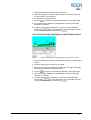
4.2.4.2 Vertical Angle with Pipe in Cradle Relative Vessel
Figure 4-6
Side view of the vertical angle with the lower pipe in the cradle
1. Select the calibration method ‘Vertical angle with pipe in cradle relative
vessel’.
2. Place the lower pipe is on deck in the cradle.
3. Enter as ‘Set point’ the measured vertical angle. The sign of the angle
should as drawn in the figure above.
4. Click on
to start the vertical angle calibration of the lower pipe.
5. The vertical angle calibration is finished after the value in the angle
offset box is changed.
6. Continue with the other calibrations or close the Tools Calibration
window with
. The angle offset will only be accepted when the
Tools Calibration window is closed with
.
PDS2000 - Application Trailing Suction Hopper
Calibration • 25
5 Acquisition
5.1 Introduction
See the chapter ‘Starting
PDS2000’ of the PDS2000
User Manual to add a
presentation in the
configuration.
When the Acquisition is started the default or last used layout will appear
on the screen. To modify the layout see ‘Layouts’ on page 28.
If a Presentation is added in the configuration, it will open simultaneously
with the Acquisition. In the Presentation, views can be added and layouts
can be saved in the same way as in the Acquisition.
5.1.1 Realtime
The Acquisition in the realtime mode can be started when the project, a
vessel configuration and a configuration are created. The Acquisition in
the realtime mode can be opened from the Control Center of PDS2000:
Click on
Click on
in the acquisition bar.
in the toolbar.
Select Acquisition > Start Realtime from the menu bar.
The Acquisition can be stopped by selecting one of the above mentioned
actions again or by closing the Acquisition window.
5.1.2 Logging
In the Acquisition the logging can be switched on and off with:
The F4-key on the keyboard.
Click on
in the toolbar.
(Un)check Logging > Enable Data Logging from the menu bar.
At the right side in the status bar the logging indicator will be switched
between
(off),
(conditional off) or
(on).
The logging can be stopped by selecting one of the above mentioned
actions again.
PDS2000 - Application Trailing Suction Hopper
Acquisition • 27
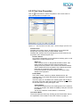
5.2 Layouts
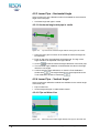
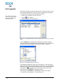
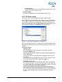
When the Acquisition is started for the first time, it will have only one view.
In the Displays window the necessary views can be added to the layout.
There are several ways to open the Displays window:
The context menu can be
opened by clicking with the
right mouse button in the
Acquisition window.
Select View > Displays from the menu bar.
Click on
in the toolbar.
Select Displays in the context menu.
Figure 5–1 The Displays window to add, to switch on/off, to remove or to rename
views
Click on
and the Add Display dialog will be opened to select a
new view. For more information about the views that can be selected for a
trailing suction hopper application see chapter ‘Views’ on page 31.
Figure 5–2 Add Display dialog to add a view
In the Displays window the views can be checked on or off. This means
that the checked views will be displayed on the screen. The views that are
checked off are not removed from the layout file. It only means that these
views are not shown on the screen. A view can be removed from the
layout file by using
in the Displays window.
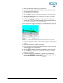
There is also a quick method to add displays or views to the layout.
Select View > Add Display… from the menu bar.
28 • Acquisition
PDS2000 - Application Trailing Suction Hopper
Click on
in the toolbar.
Select Add Display in the context menu.
Figure 5–3 Add Display in the context menu
See for an explanation of
the docking the chapter
‘Using PDS2000 –
Docking’ in the PDS2000
User Manual.
After all the wanted views are selected and placed in the right place in the
Acquisition, with or without docking, the layout can be stored. Use File >
Save Layout As… from the menu bar to save the new layout. To open
another layout use File > Open Layout… from the menu bar and select
one of the created layouts.
It is essential to save the layout that has to be used during the survey. If
something happens with one of the views, by opening the layout again
with File > Open Layout… the original layout with the right views come
back in the Acquisition and the survey can continue with the views open.
5.3 Menu Bar and Toolbar
It is possible in the Acquisition to select several options from the menu
bar or the toolbar. Below the useful options will be explained.
Edit > Select Tracking Point… ( )
Select from the list of offsets and computations a tracking point which will
be used for the guidance.
Edit > Equipment ( )
The equipment settings of the sensors can be checked or modified, only
when logging is off (see page 8).
Edit > Computations ( )
The computations can be checked or modified, only when logging is off.
Edit > Manual Input
Select one of the devices with a manual input option (as selected in the
Equipment page) and an input for the selected device can be entered.
View > Displays ( )
The Displays window will be opened. In this window views can be
switched on or off. Also views can be added, renamed or removed from
the layout (see Figure 5–1 on page 28).
View > Add Display… ( )
The Add Display dialog will be opened. In this dialog views can be added
to the layout (see Figure 5–2 on page 28).
View > Display Mode
One of the four display modes for the screen can be selected; normal
( ), night ( ), twilight ( ) and bright ( ).
PDS2000 - Application Trailing Suction Hopper
Acquisition • 29
Guidance > Guidance Settings ( )
The guidance settings can be checked or modified, only when logging is
off.
Guidance > Select Waypoint… ( )
Select an existing waypoint as active waypoint for the survey.
Guidance > New Waypoint ( )
Add a new waypoint to the active waypoint file. The new waypoint will be
located on the tracking point.
Guidance > Update Wayline
Update the wayline from the vessel to the waypoint.
Guidance > Select Work Areas…
Select one or more existing work areas as guidance in the survey.
Guidance > Enter Work Area Names
Give one or more work areas by typing the names of the work areas.
These work areas will be used as guidance in the survey.
Logging > Logging Settings ( )
The Logging page can be checked or modified, only when logging is off
(see page 19).
Logging > Enable Data Logging ( )
The data logging can be switched on or off.
Tools > Tools Settings
The Tools page of the configuration will be opened (see page 15). The
parameters in the different pages (Production parameters, Trip
Registration and Pipe Configuration) can be checked and/or modified.
Tools > Tools Calibration
The Tools Calibration window will be opened, where the suction tube(s) of
the trailing suction hopper can be calibrated (see page 21).
Tools > Start Next Trip
The next trip for the trailing suction hopper will be started.
30 • Acquisition
PDS2000 - Application Trailing Suction Hopper
6 Views
6.1 Introduction
In the Acquisition several views can be created to display the relevant
information. The minimum should be a Plan View where the vessel with
the suction tube(s) is visible, one or more Profile views for a side view of
the vessel with a suction tube and a Dredge view for the load and draught
calculations.
The views that will be discussed in this chapter are:
Plan View – General Dredge Operation (see page 32)
3D View – Online Dredge (see page 38)
Profile – Realtime Design (see page 38)
Dredge – Draught – Load – TDS (see page 46)
Dredge – Flow/Concentration Meter (see page 48)
Numerics (see page 49)
For other views, that can be used in the Acquisition, see the chapter
‘Views’ in the PDS2000 User Manual.
PDS2000 - Application Trailing Suction Hopper
Views • 31
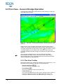
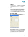
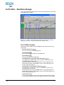
6.2 Plan View – General Dredge Operation
This plan view will show the vessel with the suction tube(s) in a top view
with additional information.
Figure 6-1
‘North Up’
Plan View – General Dredge Operation view with orientation mode
When this plan view is created, automatically the active grid model is
loaded. The active grid model will be shown in black, because there is no
color table selected for the grid model. Click on
in the toolbar or select
‘Coverage Settings’ in the context menu of the plan view to open the
Coverage Settings and select the right color table for the grid model (see
page 37).
(
At the moment a dredge layer for the first suction tube is added
automatically to the layer control. If a second suction tube is used a
second dredge layer has to be added before the suction tube becomes
visible in the plan view (see page 36).
6.2.1 Plan View Toolbar
Most of the buttons in the toolbar are available in the context menu or can
be defined in the properties of the plan view (see page 35).
Zoom In, Zoom Out ( , )
Zoom in or zoom out in the plan view.
Zoom Window ( )
Zoom in by drawing a window in the plan view.
Center Screen ( )
The cursor will change into a cross. Click in the plan view to center on
the cursor. Move the cursor to the edges of the plan view, it will
change to a diamond and the view starts panning or scrolling. To
32 • Views
PDS2000 - Application Trailing Suction Hopper
deactivate the cursor use the right mouse button. This option only
works when the ‘Follow Vessel’ mode is off.
Measure ( )
To measure distances and bearings in the plan view. On the first use
the measure starts at the vessel’s tracking point. A mouse click makes
the start at any location. The measure window shows start and end
coordinates as well as the distance and bearing between the two
locations.
Figure 6-2 Measure window
Click on
to change the presentation from grid to projection
coordinates in a selectable format.
A right click stops the measure option.
Interactive Selection ( )
If ‘in’, it is possible to select items in the plan view with the mouse, for
instance the color table bar on the right side.
Follow Vessel ( )
If ‘in’, the ‘tracking point’ will always stay in the plan view (in ‘Follow
Vessel’ mode). If ‘out’, the ‘tracking point’ can be anywhere, even
outside the plan view.
The type of the ‘Follow Vessel’ mode can be set in the properties of
the plan view (see page 35).
)
Orientation Mode (
The orientation mode of the plan view. Three options are available;
North Up, Heading Up and Fixed Skew.
North Up is that the plan view is always north up and the vessel will
rotate in the plan view. This is the default mode.
Heading Up is that the heading of the vessel is always up. In this mode
when the vessel rotates, all the data in the plan view will rotate accept
the vessel.
Fixed Skew is that the plan view has a fixed orientation. The fixed
value can be set so that the vessel is always looking up with
fluctuation to the left and right. The data in the plan view is steady and
the vessel will rotate.
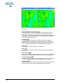
PDS2000 - Application Trailing Suction Hopper
Views • 33
Figure 6-3 Plan View with orientation mode Heading Up (left) and Fixed
Skew (right)
Set Fixed Skew From Heading ( )
Click on this button if the actual heading of the vessel has to be the
orientation in the plan view. Select then as ‘Orientation Mode’ the
Fixed Skew mode and the orientation of the plan view will change with
the heading of the vessel looking up. If the vessel starts moving the
orientation of the view is fixed.
Edit Mode ( )
If checked or ‘in’, it is possible to modify the routes and clipping
polygons and to add or edit the user maps objects. For information
about the edit mode and the user maps see the chapter ‘Views – Plan
View – Toolbar and Context Menu’ in the PDS2000 User Manual.
Undo ( )
Will reverse the last action done in the edit mode.
Redo ( )
Only active after an Undo and will reverse the last undo action of the
edit mode.
Layer Control ( )
Opens the Layers of the plan view with an overview of the background
and foreground layers that are used in the plan view (see page 36).
Coverage Settings ( )
Opens the Coverage Settings for the settings of the color tables for the
active grid model and active grid model difference (see page 37).
Properties ( )
Opens the Properties of the plan view with some extra settings for the
‘Follow Vessel’ mode and the ‘Orientation Mode’ (see below).
34 • Views
PDS2000 - Application Trailing Suction Hopper
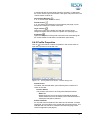
6.2.2 Plan View Properties
Click on
in the toolbar or select ‘Properties’ in the context menu to
open the Properties of the plan view.
Figure 6-4
The Properties of the Plan View – General Dredge Operation view
Follow Vessel
Enabled; the ‘Position Source’ (tracking point) on the vessel will
always stay in the plan view (in ‘Follow Vessel’ mode).
Disabled; the ‘Position Source’ (tracking point) on the vessel can be
anywhere, even outside the plan view.
Position Source
Any position computation can be selected as ‘tracking point’ on the
vessel for the ‘Follow Vessel’ mode.
Attach To
If the ‘Position Source’ is ‘Drag-head Absolute Position’ then
there will be two options that are useful as attach point.
Dredge Point; the position of the suction head will be followed.
Sensor Reference Point; the position of the attach point of the
bend with the vessel (the inlet) will be followed.
For all other position sources the attach point will be set by
default to the right point.
Follow Mode
The ‘Follow Vessel’ mode is by default Relative Motion; the
‘tracking point’ on the vessel will always be displayed in the center
of the plan view.
The other option is True Motion; the ‘tracking point’ will not stay in
the center of the plan view and the plan view will be updated when
the ‘tracking point’ is nearly leaving the view.
Vessel Radius
The minimum distance from the ‘tracking point’ on the vessel to
the edge of the plan view before the display of the plan view will
be updated.
This is only valid if the ‘Follow Mode’ is True Motion.
Orientation Mode
The three modes are North Up, Heading Up and Fixed Skew. See for
an explanation of the modes in ‘Plan View Toolbar’ on page 33.
PDS2000 - Application Trailing Suction Hopper
Views • 35
Fixed Skew Value
Give the skew for the plan view if the ‘Orientation Mode’ is set on
Fixed Skew.
Interactive Selection
Enabled; it is possible to select items in the plan view with the mouse.
Background Color
The background color of the plan view can be set.
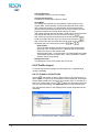
6.2.3 Plan View Layers
The layers can be used to add extra information to the plan view.
in the toolbar or select ‘Layer Control’ in the context menu to
Click on
open Layers. In Layers only the used layers will be displayed; new layers
can be added if data has to be shown in the plan view. To add data to a
new or an existing layer click on
, select one of the layers from the
list in Add Layer and edit the properties of that selected layer.
Figure 6-5
The Layers of the Plan View – General Dredge Operation view
Below only the relevant layers for a trailing suction hopper application will
be explained. Most of these layers are already filled when the plan view is
created.
Background Layers:
Both active layers are
overlapping each other. Make
a choice which active layer to
show in the plan view.
Active Grid Model Layer
This layer shows the grid model which is selected in the logging page.
Active Grid Model Difference Layer
This layer shows the difference between the active grid model and the
design model. Add an active grid model difference layer if the user
wants to see the differences between the two models.
If for both active layers another active grid model has to be used,
select Logging > Logging Settings from the Acquisition menu bar or
click on in the Acquisition toolbar and change the grid model name.
The design type and name of the design model is the same as the
specified model in the guidance page. If this is not the right one, select
Guidance > Guidance Settings from the Acquisition menu bar or click
on in the Acquisition toolbar and change the design model name in
the tab Design Model.
For both active layers a color table has to be selected. This can be
done in the layers, but the best way is to use the Coverage Settings
(see below).
36 • Views
PDS2000 - Application Trailing Suction Hopper
Foreground Layers:
(
Dredge Layer
This layer will show a suction tube as it is configured in the Pipe
Configuration (see page 17). Two dredge layers have to be added to
the layer control if two suction tubes are used.
In the properties of the second dredge layer the shape layer for the
vessel has to be Disabled, otherwise two vessels are displayed in the
view.
Color Table Layer
This layer will show the color table that is selected in the Coverage
Settings (see below) for the grid model or the grid model difference.
This layer is automatically filled when the color table is selected in the
Coverage Settings and the option ‘Show color table’ is checked.
Numerics Layer
This layer will display the value of a data item in the top or bottom of
the plan view. For each data item a separate layer has to be created.
6.2.4 Coverage Settings
Click on
in the plan view toolbar or select ‘Coverage Settings’ in the
context menu of the plan view to open the Coverage Settings.
Figure 6-6
The Coverage Settings for the plan view
If a grid model has to be shown in the plan view, check the option Grid
model on top of the window. Check then under Grid model the data type
of the grid model that has to be shown in the plan view. This data type
has to be available in the active grid model. Select the right color table for
that data type.
If a grid model difference has to be shown in the plan view, check the
option Difference and select the right color table.
PDS2000 - Application Trailing Suction Hopper
Views • 37
With the Coverage Settings is it easy to switch between the active grid
model and the active grid model difference in the plan view. Check one of
the two options and the settings in the Layers are automatically updated.
Check the option Show color table if the user wants to show the color
table of the selected option, Grid model or Difference, on the right hand
side of the plan view.
6.3 3D View – Online Dredge
If 3D DXF wireframes or 3D Studio models are available from the hopper
and the suction tube(s), a 3D View – Online Dredge can be used to show
the hopper in 3D with an 3D active grid model.
Figure 6-7
The 3D View – Online Dredge with the 3D studio models of the
hopper and the suction tube
6.3.1 3D View Toolbar
Most of the buttons in the toolbar are available in the context menu or can
be defined in the Properties of the 3D view (see page 40).
Zoom In, Zoom Out ( , )
Zoom in or zoom out in the 3D view.
Zoom Extents ( )
Show all the data in the 3D view.
Follow Vessel ( )
If ‘in’ the ‘tracking point’ will always stay in the 3D view (in ‘Follow
Vessel’ mode). If ‘out’ the ‘tracking point’ can be anywhere, even
outside the plan view.
38 • Views
PDS2000 - Application Trailing Suction Hopper
The type of the ‘Follow Vessel’ mode can be set in the Properties of
the 3D view (see page 40).
Show Spotlight ( )
If ‘in’ the spotlight window will be displayed in the 3D view. By moving
the yellow dot in the circle the light source can be changed.
Measure ( )
To measure distances and bearings in the plan view. The measure
starts always at the vessel’s tracking point. The measure window
shows start and end coordinates with the altitude (depth) as well as
the distance, bearing and elevation between the two locations.
Figure 6-8 Measure window in 3D view
Click on
to change the presentation from grid to projection
coordinates in a selectable format.
A right click stops the measure option.
Grid Axis Layer ( )
If ‘in’ the coordinate axis system is shown in the center of the view.
Color Table Layer ( )
If ‘in’ the color table will be displayed on the right side in the 3D view.
The color table will only be displayed when in the Properties a color
table is selected (see below).
Save Snapshot ( )
An image of the 3D View – Online Dredge will be saved as a BMP file.
Layer Control ( )
Opens the Layers of the 3D view with an overview of the foreground
layers that are used in the view (see page 41).
Properties ( )
Opens the Properties of the 3D view with some extra settings for the
‘Follow Vessel’ mode and for the color table (see below).
PDS2000 - Application Trailing Suction Hopper
Views • 39
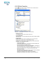
6.3.2 3D View Properties
Click on
in the toolbar or select ‘Properties’ in the context menu to
open the Properties of the 3D view.
Figure 6-9
The Properties of the 3D View – Online Dredge
Background Color
The background color of the 3D view can be set.
Color Table Name
Select the name of the color table that will be used to display the data
in the 3D view.
Follow Vessel
Enabled; the ‘Position Source’ (tracking point) on the vessel will
always stay in the 3D view (in ‘Follow Vessel’ mode).
Disabled; the ‘Position Source’ (tracking point) on the vessel can be
anywhere, even outside the 3D view.
Follow Vessel Mode
If the option ‘Follow Vessel’ is Enabled, this mode will define how
the view will follow the ‘Position Source’.
Grid North will show the data with a fixed orientation, although the
user can rotate the view. The vessel will rotate.
Vessel North will show the vessel with a fixed orientation, although
the user can rotate the view. The grid model data will rotate.
Allow Vessel Angle
This option is only valid when the option ‘Follow Vessel’ is Enabled
and the ‘Follow Vessel Mode’ is Vessel North.
Enabled; the orientation of the vessel can be modified.
Disabled; the orientation of the vessel in the view is always up.
40 • Views
PDS2000 - Application Trailing Suction Hopper
Position Source
Any position computation can be selected as ‘tracking point’ on the
vessel for the ‘Follow Vessel’ mode.
Show Spotlight
Enabled; the spotlight window will be displayed in the view.
6.3.3 3D View Layers
The layers can be used to add extra information to the 3D view.
in the toolbar or select ‘Layer Control’ in the context menu to
Click on
open Layers. In Layers only the used layers will be displayed; new layers
can be added if data has to be shown in the plan view. To add data to a
new or an existing layer click on
, select one of the layers from the
list in Add Layer and edit the properties of that selected layer.
Figure 6-10
The Layers of the 3D View – Online Dredge
Below only the relevant layers for a trailing suction hopper application will
be explained. Most of these layers are already filled when the plan view is
created.
Foreground Layers:
GridAxis Layer
This layer displays the coordinate axis in the center of the view.
Active Grid Model Layer
This layer shows the grid model which is selected in the logging page.
Color Table Layer
This layer will show the color table that is selected in the Properties
(see above).
This layer is automatically filled when the color table is selected in the
Properties and the button ‘Color Table Layer’ ( ) is ‘in’.
3D Dredge Track Layer
This layer can show the suction tube(s) and the vessel as wireframes
or as 3D Studio models. The bend, the upper pipe, the lower pipe and
the suction head has to be available as separate wireframes or models
to have a real animation of the working situation.
Select in the properties of the layer for the Dredge Tool Absolute
Computation the Drag-head Absolute Position of the suction tube that
has to be tracked. Select for the 3D objects first the suction head, then
the lower pipe, the upper pipe, the bend and as last 3D object the
vessel.
PDS2000 - Application Trailing Suction Hopper
Views • 41
6.4 Profile – Realtime Design
This view will show the vessel with one of the suction tubes as a side view
with additional information.
Figure 6-11 Profile – Realtime Design view with a right view of the vessel, a
starboard suction tube, an active grid model and a design model
6.4.1 Profile Toolbar
The buttons of the toolbar are also available in the context menu of the
profile view.
)
Zoom In, Zoom Out (
Zoom in or Zoom out in the profile view.
Zoom Window ( )
Zoom in by drawing a window in the profile view.
Zoom Extents ( )
Show all the data in the profile view.
)
Horizontal Zoom In and Horizontal Zoom Out (
The display in the profile view can be zoomed in or out only in the
horizontal direction of the view.
These two buttons are only available when in the properties of the
profile view the option ‘Scale Mode’ is set on Fixed Vertically or on
Scale Freely (see page 44).
Vertical Zoom In and Vertical Zoom Out (
)
The display in the profile view can be zoomed in or out only in the
vertical direction of the view.
These two buttons are only available when in the properties of the
profile view the option ‘Scale Mode’ is set on Fixed Horizontally or on
Scale Freely (see page 44).
Center Screen ( )
The cursor will change into a cross. Click in the profile view to center
on the cursor. Move the cursor to the edges of the view, it will change
42 • Views
PDS2000 - Application Trailing Suction Hopper
to a diamond and the view starts panning or scrolling. To deactivate
the cursor use the right mouse button. This option only works when the
‘Follow Vessel’ mode is off.
Vertical Auto Ranging ( )
If ‘in’, a vertical zoom extents is active.
Follow Vessel ( )
If ‘in’, the attach point selected in the properties (see page 43) will
always be located in the center of the view.
Layer Control ( )
Opens the Layers of the profile view with the overview of the
foreground layers that are used in the profile view (see page 44).
Properties ( )
Opens the Properties of the profile view with some extra settings for
the ‘Follow Vessel’ mode and the ‘Scale Mode’ (see below).
6.4.2 Profile Properties
Click on
in the toolbar or select ‘Properties’ in the context menu to
open the Properties of the profile view.
Figure 6-12
The Properties of the Profile – Realtime Design view
Follow Vessel
If Enabled, the selected attach point will always be located in the
center of the view.
Position Source
This position source has to be ‘Drag-head Absolute Position’.
Attach To
Dredge Point; the end of the suction head will be followed.
Sensor Reference Point; the attach point of the bend with the
vessel (the inlet) will be followed.
Profile View Side
For a profile view four different view sides can be selected; Left side,
Right side, Front and Back of the vessel with the suction tube(s). The
selected side view has to be created in the Geometry page of the
vessel configuration (see page 5).
PDS2000 - Application Trailing Suction Hopper
Views • 43
Heading Selection
The heading selection has to be Heading.
Vertical Auto Ranging
If Enabled, a vertical zoom extents is active.
Scale Mode
The display of the profile view has different scaling options; Fixed
Aspect Ratio, Fixed Vertically, Fixed Horizontally and Scale Freely.
With Fixed Aspect Ratio, the ratio between the horizontal and the
vertical scale is fixed. After using one of the zoom functions the ratio
between horizontal and vertical scale will stay the same.
With Fixed Vertically the vertical scale is fixed and the horizontal scale
will change after the use of one of the zoom functions (
).
With Fixed Horizontally the horizontal scale is fixed and the vertical
).
scale will change after the use of one of the zoom functions (
With Scale Freely the horizontal and vertical scale can be changed
and
).
separately with one of the zoom functions (
Aspect Ratio
This is the ratio between the horizontal and vertical scale used in
the profile view. An aspect ratio of 1 indicates that the horizontal
scale is the same as the vertical scale.
With an aspect ratio >1 the information in horizontal direction will be
compressed and with an aspect ratio <1 the information in vertical
direction will be compressed.
Background Color
The background color of the profile view can be set.
6.4.3 Profile Layers
For the left panel and the graphics of the profile view, a separate layer
control is available.
6.4.3.1 Graphics of the Profile
Click on
in the toolbar or select ‘Layer Control’ in the context menu to
open Layers. In Layers only the used layers will be displayed; other layers
can be added if data has to be shown in the profile view. To add data to a
new or an existing layer click on
, select one of the layers from the
list in the Add Layer dialog and edit the properties of that selected layer.
Only the relevant layers for the trailing suction hopper application will be
discussed.
Figure 6-13
44 • Views
The Layers of the Profile – Realtime Design view
PDS2000 - Application Trailing Suction Hopper
Active Grid Model Profile Layer
This layer shows the grid model which is selected in the logging page.
Select Guidance > Guidance
Settings in the menu bar of the
Acquisition and add in the tab
Design Model the values for
the under and over dredge
limit.
Active Design Model Profile Layer
This layer shows the profile of the design model which is created in the
guidance.
It is also possible to show an under and over dredge limit in the profile
view (see Figure 6-11 on page 42). By default the dredge limits will be
displayed with a default color. In the properties of the Active Design
Model Profile Layer the dredge limits can be switched on/off and the
color can be changed.
Dredge Layer
This layer shows the vessel with selected suction tube (‘ Drag-head
Absolute Position’). If two suction tubes are used, only in the front or
back view both two suction tubes can be shown.
It is also possible to open two profile views to display both suction
tubes in a side view, one with a right view and one with a left view.
Numerics Layer
This layer will display the value of a data item in the top or bottom of
the profile view. For each data item a separate layer has to be created.
6.4.3.2 Left Panel of the Profile
It is possible to show an up/down indicator in the left panel of the profile
view (see Figure 6-11 on page 42). Click with the right mouse button in
this panel, select ‘Layer Control’ in the context menu and select the Up
Down Indicator.
Click on
and select for the ‘Up/Down Source Item’ the
computation ‘ Design Difference’ (in ‘ Drag-head Absolute Position’) to
show the difference between the end of the suction head and the Z-value
of the design model.
Another option is to select the computation ‘ Absolute Z Dredge
Head(1)’ to show the depth of the end of the suction head.
Figure 6-14 Properties of the Up Down Indicator with the two possible
computations
PDS2000 - Application Trailing Suction Hopper
Views • 45
6.5 Dredge – Draught – Load – TDS
This view will give the draught, load and Tons Dry Solid information in a
time based editor in combination with a numerics view.
If no hopper sensors are used, so no tons dry solid can be calculated,
then there is also a stripped view with only the draught and load
information. This view is called ‘Dredge – Draught – Load’.
Figure 6-15
Dredge – Draught – Load – TDS view with 4 draught sensors
By default are in the time based editor the mean draught and the load
selected. In the numerics part of the view are four pages by default
defined; Draught Sensor, Hopper Sensor, Load and TDS (see below). For
the ‘Dredge – Draught – Load’ view only the Draught Sensor and Load
pages are defined.
In the time based editor a context menu is available to setup the editor or
to add extra items to the editor. In the context menu the options Add
Channel, Layer Control and Properties are available.
The items in the four different pages of the numerics part will be explained
below. In the numerics part context menus are available to modify the
pages (see the Numerics view on page 49 for details).
6.5.1 Draught Sensor
Figure 6-16
The draught sensors with their residuals
In this example are four draught sensor mounted on the vessel. The
draught sensor values as displayed in this page are corrected for the
water density. Through the corrected draught values (also corrected for
the offsets) a plane will be calculated, which will results in a mean
46 • Views
PDS2000 - Application Trailing Suction Hopper
draught. The residuals are then the difference between the calculated
plane and the corrected draught values. The plane will become the
horizontal level of the vessel.
When only two sensors are used no plane can be calculated, so there are
no residuals. For three sensors a plane can be calculated, but the plane
goes always through the three points, so there are no residuals. The
residuals will be calculated with four or more draught sensors.
6.5.2 Hopper Sensor
Figure 6-17
Hopper sensors with their residuals
In this example are four hopper (level) sensors mounted on the vessel.
The hopper sensors are mounted in or on top of the bunkers to measure
the amount of dredged material. With use of the hopper table in the
Production parameters page of the Tools (see page 15) the volume of the
dredge material in the bunkers can be calculated.
The residuals and the mean hopper level are calculated the same way as
for the draught sensor (see above).
6.5.3 Load
Figure 6-18
Load page
Mean Vessel Draught
The mean vessel draught as calculated from the draught sensors (see
above).
Empty Weight
This is the Empty Ship Weight as entered in the Production
parameters page of the Tools (see page 15).
Displacement
This is the displacement as is calculated from the draught table in the
Production parameters page of the Tools (see page 15).
Load
The load is the difference between the displacement and the empty
weight. Before the load is calculated the displacement is corrected for
the water density.
Load = (Displacement x Water Density) – Empty Weight
PDS2000 - Application Trailing Suction Hopper
Views • 47
6.5.4 TDS
Figure 6-19
TDS page
Tons Dry Solid
The tons dry solid (TDS) is calculated from the water density (ρw), the
product density (ρp), the hopper density (ρh) and the hopper volume
(V) with the formula:
TDS = {(ρh – ρw) / (ρp – ρw)} x ρp x V
Hopper Density
The hopper density is calculated from the load and the hopper volume.
Hopper Density = Load / Hopper Volume.
Hopper Volume
This is the volume as it is calculated from the hopper table in the
Production parameters page of the Tools (see page 15).
Mean Hopper Level
The mean hopper level as calculated from the hopper sensors (see
above).
6.6 Dredge – Flow/Concentration Meter
Figure 6-20 Dredge – Flow/Concentration Meter view with the information of the
starboard suction tube
(
This view displays the velocity (V) and the density (C) of the dredge
production. With these two values the production (Q) can be calculated.
The view can only display information if in the Equipment page a ‘Dredge
Production’ device is selected (see page 10).
The production is presented in the view as the crossing between the two
needles. In principal how higher the crossing of the two needles the
higher the production is. The production is also depending on the pipe
48 • Views
PDS2000 - Application Trailing Suction Hopper
diameter of the suction tube. This pipe diameter can be set in the
properties of the Dredge Positioning System (see page 10).
By default this view has two meters in the view, one for port and one for
starboard. In the properties of the context menu one meter can be
switched off (disabled) and the range of the meters can be adjust.
6.7 Numerics
This view will show the relevant data as alpha numeric values.
Figure 6-21
Numerics view
This view is empty when it is opened for the first time. Click with the right
mouse button in the left panel of the view and select ‘Add New Page’ to
add a name for the page. Because the view has no name yet, a dialog will
be opened where a new name can be entered.
Click with the right mouse button in the right panel and select ‘Edit Page’
and select in the numerics page configuration the data that have to be
shown in the Numerics view.
Figure 6-22
Numerics page configuration to select data for the Numerics view
Select one of the available data elements at the bottom of the window and
click on
to add this data element from a device or
PDS2000 - Application Trailing Suction Hopper
Views • 49
computation to the page. With
the selected data element
can be added between the selected items in the page layout.
With
a separation can be added between the selected
items, while with
a separation can be added below the
last selected item in the page layout.
Select a separation and click on
to add text to the separation.
With this option headers can be made between the selected items. It is
also possible to change the color, background, font and font size.
With
removed.
a data element or separation in the page layout can be
In the Numerics view the font, the background, etc. can be changed by
selecting the option ‘Properties’ from the context menu. Double clicking
on an item in the Numerics view gives also the possibility to change the
color, the font and font size of that item.
50 • Views
PDS2000 - Application Trailing Suction Hopper
Dredge Production - 8, 10
Dredge Status - 8, 10
Dredge View - 31
DXF File - 5
Index
─E─
Equipment - 8, 9, 13, 14, 29, 48
─F─
Follow Vessel - 33, 34, 35, 38, 39, 40, 41, 43
─G─
3D DXF File - 38
3D Studio Model - 38
3D View – Online Dredge - 31, 38
Geo Calculator - 4
Geometry - 5, 8, 9, 10, 11, 15, 16
GPS - 11, 12
Grid Model - 19, 32, 37
Grid Model Difference - 37
Guidance - 14, 30, 36, 45
─A─
─H─
Active Design Model Profile Layer - 45
Active Grid Model - 34, 36, 37, 38
Active Grid Model Difference Layer - 36
Active Grid Model Layer - 36, 41
Active Grid Model Profile Layer - 45
Advanced Computation - 12, 13
Attach Point - 35, 43
Hopper Density - 48
Hopper Table - 16, 48
Horizontal Angle Calibration - 21, 22, 24
─B─
─L─
Bend - 5, 6, 10, 17, 41
BMP File - 39
Layout - 27, 28, 29
Load - 15, 46, 47, 48
Load and Draught - 8, 9, 10
Logging - 19, 27, 30, 36, 41, 45
Lower Pipe - 5, 6, 7, 18, 21, 24, 25, 41
─3─
─C─
Calibration - 21, 30
Color Table - 32, 33, 34, 36, 37, 38, 40, 41
Color Table Layer - 37, 41
Compass - 8, 9
Contour - 5, 7
Coordinate System - 4, 11
Coverage Settings - 34, 36, 37, 38
─D─
Data Sources - 14
Datum Transformation - 11
Depth Sensor - 8, 9, 10, 12, 14
Design Model - 14, 36, 45
Displacement - 15, 47
Draught - 8, 9, 10, 11, 15, 46, 47
Draught Table - 15, 47
Dredge – Draught – Load – TDS - 31, 46
Dredge – Flow/Concentration Meter - 31, 48
Dredge Layer - 37, 45
Dredge Positioning System - 8, 10, 15
PDS2000 - Application Trailing Suction Hopper
─I─
Inlet - 8, 10, 35, 43
─N─
Numerics Layer - 37, 45
Numerics View - 31, 49, 50
─O─
Over Dredge Limit - 45
─P─
Pipe Configuration - 15, 17, 30, 37
Pitch - 12
Pitch Correction - 12
Plan View - 31, 32, 33, 34, 35, 36, 37, 38, 39
Plan View – General Dredge Operation - 31, 32
Positioning System Geogs - 8, 11
Product Density - 15, 48
Production Parameters - 10, 15, 30
Profile – Realtime Design - 31, 42
Index • 51
Profile View - 31, 42, 43, 44, 45
Project Configuration - 4
─R─
Restricted Area - 14
Roll - 12
Roll Correction - 12
Route - 14
RTK - 11, 12
─S─
Sea Level - 9, 14
Set Point - 22, 23, 24, 25
Suction Head - 5, 7, 10, 11, 18, 20, 41, 45
Suction Tube - 5, 8, 10, 17, 19, 21, 31, 32, 37,
38, 41, 42, 45
─T─
Tide Computation - 13
Tide Gauge - 8, 11, 12
Tide Station - 12
Tons Dry Solid - 46, 48
Tools - 10, 15
Tracking Point - 29, 33, 35, 38, 39, 40
Trip - 12, 16, 30
Trip Info - 8, 12
Trip Registration - 15, 16, 30
─U─
Under Dredge Limit - 45
Up/Down Indicator - 45
Upper Pipe - 5, 6, 17, 21, 22, 23, 41
─V─
Vertical Angle Calibration - 21, 23, 25
VRU - 8, 12
VRU Calibration - 12
─W─
Water Density - 15, 46, 47, 48
Waypoint - 14, 30
Wireframe - 5, 7, 17, 18, 38
Work Area - 14, 30
52 • Index
PDS2000 - Application Trailing Suction Hopper