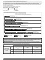
1
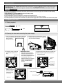
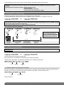
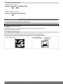
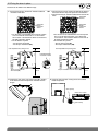
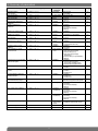
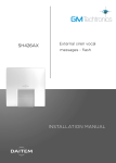
External Siren & Strobe
SH423AX
1. Introduction
IMPORTANT
• Some functions are only available with versions 2.0.0 or later (press
on the control panel keypad to
check the version).
• The operating differences with former ranges are described in the compatibility booklet available in the Daitem installers
section at www.daitem.co.uk.
In addition to the protection provided by the control panel with built-in siren and keypad, the external siren with flashing
strobe makes it possible to:
• deters intruders and alert neighbours (external sounding mode),
• easily locate the alarm (flashing strobe).
If a fire is detected, the siren is triggered for 5 minutes in fire sounding mode.
Thanks to its built-in transmitter, the siren informs the control panel when it has a battery problem.
If somebody attempts to pull the siren off the wall, it sounds and then triggers all the alerts and deterrents via the control panel.
2. Preparing the siren
2.1 Tooling required
6 mm
PZ 2
IMPORTANT: the fixing screws
and wall plugs are not supplied.
2.2 Opening the siren and connecting the power supply
1. Insert a screwdriver into the bottom right-hand
corner between the base and the siren and
apply pressure
to open the siren.
2. Place the siren on a flat surface, remove
the base by inclining it at a 45° angle (A)
and pull it downwards (B).
B
A
45°
3. Lift up the screw cover and
remove the screw from its
slot.
Screw cover
4. Guarantee sticker
Remove the pre-cut part of
the sticker and stick it to the
guarantee certificate in the
user manual supplied with the
control panel. If you are
adding the siren to an existing
system, use the guarantee
sticker provided with this
product.
5. Position the power pack on the guide rails.
6. Slide the power pack to the left until it is
locked into place.
SH421AX
Coller sur certif
A12260A0963C
7. Reposition the
battery cover and
screw it in place
using one of the
screws (A).
Unlocking key
Locking screw
and battery
cover screw
A12260A0963C
SH421AX
Guarantee
sticker
8. Position the locking screw in its slot.
Locking screw slot
Siren opening
A
Screw slot
2
Bottom view of siren
To remove the lithium power pack, press on the unlocking key and slide the pack towards the right.
IMPORTANT
• When the siren is powered, it will issue a long beep and automatically switch to installation mode (tamper mechanism
disabled).
• If the siren does not respond as it should: - disconnect the power pack,
- wait for 2 minutes,
- reconnect the lithium power pack,
- check the siren issues a long beep as it should.
3. Recognition programming
Recognition programming allows the siren to be recognised by the control panel.
It must be done with the control panel and siren in installation mode. If they are not in installation mode, enter:
then
master code
installer code
IMPORTANT
• The siren does not need to be placed close to the control panel for recognition programming. In fact, it is advisable to move it
away from the panel (to a distance of at least 2 m).
• The control panel gives the siren a n° during recognition programming.
Siren recognition programming sequence:
“bip, off,
control panel”
“bip”
))
“beeeep”
)))
))
“bip, siren n°”
)))
IMPORTANT: the control panel and
siren issue three short beeps to
indicate a programming error. When
this happens, perform recognition
programming again from the start.
10 s max.
Briefly press
the siren “test”
button
Press and hold “Off”
until the control panel
responds
The siren issues
an audible signal to
confirm programming
The control panel
announces
the siren n°.
4. Setting the parameters
IMPORTANT: all parameter-setting must be done using TwinLoad® software available in the Daitem installers section at
www.daitem.co.uk.
The control panel and siren must be in installation mode to set the siren’s parameters. If they are not, enter:
then
master code
installer code
The siren’s parameters are factory-programmed.
Each parameter can nevertheless be modified using the control panel keypad.
To set the siren’s parameters, first choose the parameters to be modified and then enter:
siren n°
parameter
n°
parameter
value
4.1 Delayed alarm sounding upon intrusion
Siren alarm sounding can be delayed by 60 seconds maximum. This gives users enough time to disarm the system before
the alarm siren sounds if, for instance, they have pressed the wrong button. To delay sounding, enter:
siren n°
from 0 to 60 s
Factory setting: 0 s
3
4.2 Setting the sounding parameters
4.2.1 Duration of alarm sounding
4.2.2 Level of sounding
To modify the duration of sounding, enter:
To modify the level of sounding, enter:
siren n°
siren n°
from 20 to 180 s
0: normal
1: quiet
Factory setting: 0
Factory setting: 90 s
4.3 Type of sounding
To modify the type of siren sounding, enter:
siren n°
0: internal
1: external
Factory setting: external
4.4 Sound level of disarm and arm command indications
For greater user-friendliness, the sound level can be increased or decreased. To do this, enter:
siren n°
from 1 to 8
Factory setting: 4 = average
4.5 Transfer of arm and disarm commands
To modify the transfer of indications, enter:
siren n°
Factory setting: 0
0: disabled
1: sounding
3: sounding and flashing
5: flashing
4.6 Indication of audible signals and door bell
This function is factory-set to be disabled. It can be activated if required. To do this, enter:
siren n°
0: disabled
1: sounding
Factory setting: 0
4.7 Validation of radio link in installation mode
This function is used to validate the radio link test in installation mode on 1 of the 2 radio bands.
To switch to 2 bands, enter:
siren n°
0: validation on 1 of the 2 bands
1: validation on 2 bands
Factory setting: 0
4.8 Triggering upon intrusion
The alarm is factory-set to be triggered as soon as an intrusion is detected. This function can be deactivated or activated for
intrusion confirmed indications only. To do this, enter:
siren n°
Factory setting: 1
0: disabled
1: single or confirmed intrusion
2: confirmed intrusion only
4
4.9 Protection system armed indication
When this function is enabled, the siren issues a series of 4 beeps to indicate that the system is armed. This function is not
activated by default.
siren n°
0: disabled
1: quiet sounding (“bip, bip, bip, bip”)
Factory setting: 0
4.10 Alarm indication in armed presence mode
The siren is factory-set to sound loudly for 15 s in case of intrusion. This function can be modified. To do this, enter:
siren n°
0: disabled
1: quiet sounding (4 beeps)
2: loud sounding (15 s)
4: quiet sounding (4 beeps) and flashing
5: loud sounding (15 s) and flashing
7: flashing
Factory setting: 2
4.11 Duration of flashing
To modify the duration of flashing, enter:
siren n°
from 1 to 60 min
Factory setting: 15 mn
4.12 Triggering following a communication network interruption
When this function is enabled, loud sounding can be triggered (except when parameter 26 is set at 0).
siren n°
Factory setting: 0
0: disabled
1: loud sounding triggered if the system is totally armed
2: loud sounding triggered 24/24
4.13 Radio tamper
If the radio links are deliberately tampered with, the siren is triggered.
To activate or deactivate the radio tamper system, enter:
siren n°
0: disabled
1: enabled
Factory setting: 1
4.14 Indication of break-in following intrusion
The “break-in indication” function lets a neighbour or correspondent know that an intruder is still on the monitored premises.
When intrusion occurs, the strobe is activated continuously. After a period of 3 minutes without intrusion, the flashing
becomes discontinuous (on for 6 seconds, off for 6 seconds) indicating that there is no intruder on the premises. If the
intruder returns, the strobe is reactivated continuously once more (see diagram).
The function “Break-in Indication” is active if parameter “5” , “Flash duration” is greater than 3 minutes.
To modify the break-in indication, enter:
siren n°
Factory setting: 0
0: disabled
1: enabled
2: enabled 24 h
5
4.15 Visual localisation of flashing strobe following break-in
The “visual localisation” function can be triggered following a “break-in indication” (if this function has been enabled) or once
the “flashing duration” has run its course. By extending the effect of the flashing strobe (on for 6 seconds, off for 16
seconds), the “visual localisation” function helps the user’s correspondent to visually localise the premises where the alarm
has been triggered (see diagram).
To modify the strobe’s visual localisation function, enter:
siren n°
0: disabled
1: enabled 2 h
2: enabled 48 h
Factory setting: 0
How the different functions work: • duration of flashing (parameter 5)
• break-in indication (parameter 35)
• visual localisation of flashing strobe (parameter 36)
Duration of flashing: 2 min
Break-in indication: enabled or disabled
Visual localisation: disabled
2 min
Duration of flashing: 5 min
Break-in indication: enabled
Visual localisation: disabled
2 min
3 min
INTRUSION
5 mn
3 min
Duration of flashing: 3 min
Break-in indication: enabled 24 h
Visual localisation: disabled
24 h
24 h + 3 mn
2 min
Duration of flashing: 2 min
Break-in indication: enabled or disabled
Visual localisation: enabled 2 h
2h
2 h + 2 min
3 min
2 min
Duration of flashing: 5 min
Break-in indication: enabled
Visual localisation: enabled 2 h
2h
2 h + 5 min
3 min
24 h
48 h
Duration of flashing: 3 min
Break-in indication: enabled 24 h
Visual localisation: enabled 48 h
72 h + 3 min
Continuous flashing
Flashing: On 6 s
Off 16 s
Flashing: On 6 s
Off 6 s
IMPORTANT
• If the “break-in indication” function (parameter 35) and/or the “visual localisation” function (parameter 36) is/are activated,
the installer should be aware that this will use up the batteries at a faster rate than usual when the complete indication cycle
is triggered (see the table below for the power pack battery life according to selected parameters).
• When parameters 35 and/or 36 are selected with a long-duration indication value (value 2), we recommend changing the
power pack on a yearly basis.
Power pack battery life according to the programming of parameters 35 and 36:
Parameter 35: “break-in indication function”
Parameter 36:
“visual localisation
function”
0
1
2
0
5 years
10 complete activations/year
(factory)
5 years
8 complete activations/year
2 years
2 complete activations/year
1
5 years
7 complete activations/year
5 years
4 complete activations/year
2 years
2 complete activations/year
2
2 years
2 complete activations/year
2 years
2 complete activations/year
2 years
1 complete activation/year
6
4.16 Allocation of siren to alarm group
To allocate the siren to one or several alarm system groups, enter:
...
siren n°
groups from 1 to 8 depending
on the type of control panel
Factory setting: all groups
Example, to allocate siren n° 1 to Group 2 and Group 3, enter:
4.17 Type of indication
4.17.1 For warnings
To modify the type of warning indication, enter:
siren n°
0: disabled
1: sounding (2 s)
2: sounding (2s) and flashing (5 s)
3: flashing (5 s)
Factory setting: 3
4.17.2 For deterrence
To modify the type of deterrence indication, enter:
siren n°
0: disabled
1: sounding (5 s)
2: sounding (5 s) and flashing (5 s)
3: flashing (5 s)
Factory setting: 2
4.17.3 For prealarms
To modify the type of prealarm indication, enter:
siren n°
0: disabled
1: sounding (loud for 15 s)
2: sounding (loud for 15 s) and flashing (15 s)
3: flashing (15 s)
Factory setting: 2
4.18 Anti-tamper switch triggering
To modify the conditions under which the anti-tamper switch will activate the siren, enter:
siren n°
0: enabled 24 h/day
1: enabled if system totally armed
Factory setting: 1
4.19 Checking
To check parameter-setting, enter:
siren n°
parameter
n°
Example, to check on siren n° 1, parameter 4: duration of sounding, enter
“4, bip, 9, 0”
7
4.20 Deletion of parameters
• To delete a parameter, enter:
siren n°
parameter
n°
• To delete all parameters, enter:
siren n°
5. Installing the siren
5.1 Choosing the best place to install the siren
IMPORTANT: make sure there is a distance of at least 2 metres between each product, except between two detectors.
The siren should preferably be placed:
• at a height,
• far away from possible sources of electrical interference (electricity meter, telephone box, etc.).
Never fix the siren to a metal wall.
5.2 Testing the radio range
Before fixing the siren in place, test its radio range in the chosen location by putting it there.
If the test is satisfactory, fix the siren in place. Otherwise, move it to a different location.
1. Press the test button.
2. The control panel
issues the message:
8
“bip, siren X”
5.3 Fixing the siren in place
The siren can be fixed in two different ways:
Pozidriv 2
1. • Remove the tamper mechanism washer located at
the back of the base.
OR
• Remove the two fixing washers located at the back of
the base. Remove any extra parts from the washers.
• Remove the tamper washer located at the back of the
base.
Detachable
washers
Detachable
tamper
mechanism
washer
Detachable
tamper
mechanism
washer
• For the siren to be installed there must be a space
of 6 cm to the left of the base, 4 cm above and
18 cm below. This clearance allows for the siren to
be easily opened or locked.
• Fix the base at 3 points:
- the two fixing points (A),
- the tamper mechanism (AP).
Insert adjustable fixing washers here
• For the siren to be installed there must be a space
of 6 cm to the left of the base, 4 cm above and
18 cm below. This clearance allows for the siren to
be easily opened or locked.
• Fix the base at 3 points:
- the two fixing points (B),
- the tamper mechanism (AP).
Insert adjustable fixing washers here
4 cm
4 cm
Detachable tamper
mechanism washer
6 cm
6 cm
wall
wall
Tamper mechanism hole
with washer (AP)
Tamper mechanism hole with washer (AP)
18 cm
18 cm
2. Position the siren open at an angle of 45° (A) in relation
to the base and insert the pivots on the base into the
hinges.
3. Close the siren and lock it using the screw located
inside the product.
A
Siren opening
45°
Bottom view of siren
Siren locking
(A) 45°
9
6. Performing a real test
Testing triggering when there is an attempt to remove the siren
IMPORTANT: the sound level of the siren can cause hearing disorders. The necessary precautions must therefore be taken
before testing siren triggering.
1. Loosen the siren locking screw.
2. Open the siren.
3. Check triggering:
• of the siren
• of the control panel
• of the telephone dialler
4. Issue an Off order.
7. Maintenance
7.1 Fault indications
The control panel supervises and identifies the siren.
It monitors the state of the:
• power supply,
• radio link,
• tamper contact.
If a fault is memorised the control panel issues a voice message to indicate the fault following a system command (see §
Fault indications in the control panel installation manual).
7.2 Changing the battery
• The lithium battery pack must be replaced by the same type of pack with the same technical characteristics,
i.e. 2 x (3.6 V – 13 Ah).
• We advise you to use the DAITEM BatLi22 pack available in the catalogue in order to guarantee individual safety
and equipment reliability.
• Dispose of the waste lithium power pack in an appropriate recycling bin.
To change the battery:
1. send a disarm command,
2. switch the control panel to installation mode:
then
master code
installer code
3. remove the siren from the wall,
4. remove the faulty lithium power pack,
5. wait for 2 minutes before connecting the new lithium pack,
6. close the siren and put it back on its base,
7. switch the control panel to user mode:
installer code
8. test triggering.
10
Li
8. Summary of parameters
Parameter description
Delayed sounding
upon intrusion
Sounding duration
Flashing duration
Type of sounding
Sound level of disarm/arm
indications
Transfer of disarm/arm
indications
Parameter-setting sequence
** 4 * siren n° * 3 * ?? **
Factory
parameter
0: immediate
** 4 * siren n° * 4 * ??? **
** 4 * siren n° * 5 * ?? **
** 4 * siren n° * 10 * ? **
90 s (60 s Spain)
15 min
external
** 4 * siren n° * 11 * ? **
4: average
** 4 * siren n° * 12 * ? **
0: disabled
Indication of audible signals
and door bell
Validation of radio link
in installation mode
Sounding level
** 4 * siren n° * 13 * ? **
0: disabled
** 4 * siren n° * 15 * ? **
0: on one
of 2 bands
0: normal
Triggering upon intrusion
** 4 * siren n° * 20 * ? **
Protection system armed
indication
Alarm indication in armed
presence mode
** 4 * siren n° * 21 * ? **
** 4 * siren n° * 19 * ? **
1: single
or confirmed
intrusion
1: disabled
** 4 * siren n° * 22 * ? **
2: loud sounding
(15 s)
Triggering upon communication ** 4 * siren n° * 26 * ? **
network interruption
0: disabled
Radio tamper
** 4 * siren n° * 27 * ? **
1: enabled
Indication of break-in following ** 4 * siren n° * 35 * ? **
intrusion
0: disabled
Visual localisation of flashing
following intrusion
** 4 * siren n° * 36 * ? **
0: disabled
Allocation of a siren to one
or several intrusion groups
Type of warning indication
** 4 * siren n° * 37 * ? **
all groups
** 4 * siren n° * 72 * ? **
3: flashing
Type of deterrence indication
** 4 * siren n° * 73 * ? **
2: sounding
and flashing
Type of prealarm indication
** 4 * siren n° * 74 * ? **
2: sounding
and flashing
Anti-tamper switch triggering
** 4 * siren n° 75 * ? **
1: enabled if
system totally
armed
Deletion of all parameters
Deletion of one parameter
** 4 * siren n° * 197 ***
** 4 * siren n° * parameter n° ** 0 **
Possible values
from 0 to 60 s
0: immediate
from 20 s to 180 s
from 1 to 60 min
0: internal
1: external
from 1 to 8
0: disabled
1: sounding
3: sounding and flashing
5: flashing
0: disabled
1: enabled
0: validation on 1 of 2 bands
1: validation on 2 bands
0: normal
1: quiet
0: disabled
1: single or confirmed intrusion
2: confirmed intrusion only
0: disabled
1: sounding
0: disabled
1: quiet sounding (4 beeps)
2: loud sounding (15 s)
4: quiet sounding (4 beeps)
and flashing
5: loud sounding (15 s) and flashing
7: flashing
0: disabled
1: loud sounding triggered
if the system is totally armed
2: loud sounding triggered 24/24
0: disabled
1: enabled
0: disabled
1: enabled
2: enabled 24 h
0: disabled
1: enabled 2 h
2: enabled 48 h
Selection of group(s): from 1 to 8
depending on type of control panel
0: disabled
1: sounding
2: sounding and flashing
3: flashing
0: disabled
1: sounding
2: sounding and flashing
3: flashing
0: disabled
1: sounding
2: sounding and flashing
3: flashing
0: enabled 24 h/day
1: enabled if system totally armed
Page
3
4
5
4
4
4
4
4
4
4
5
5
5
5
5
6
7
7
7
7
7
8
8
11
9. Technical data
Technical specifications
Acoustic level
Sounding duration
External sounding
Fire sounding
Transfer of Arm/Disarm indications
Environment
Power supply
Battery life
Average current consumed
Average humidity rate
SH421AX, SH422AX, SH423AX, SH421AI sirens
109 dB at 1 m
20 s to 180 s
1400 Hz to 1600 Hz
700/900 Hz, sounding duration: 5 min.
Audible
External
TwinPower® via lithium power pack (2 x 3.6 V)
5 years in normal conditions of use
327 µA
5% to 75% without condensation at 25°C possibly varying between
85% & 95% for 30 days over the course of the year
TwinBand® 400/800 MHz
Radio, lithium pack, tamper
-25°C to + 70°C
• opening
• removal
IP 54/IK 08
248 x 248 x 84 mm
2.5 kg (with battery)
grade IV according to standard EN 50131-4
class IV according to standard EN 50130-5
Radio links
Supervision
Operating temperature
Tamper protection against
Degrees of mechanical protection
WxHxD
Weight
Security grade
Environmental class
DECLARATION OF CONFORMITY
GB
Manufacturer: Hager Security SAS
13
Address: F-38926 Crolles Cedex - France
Product type: External siren
Trade mark: Daitem
We declare under our sole responsibility that the product to which this declaration
relates is compliant with the essential requirements of the following directives:
• R&TTE directive: 99/5/EEC
• Low voltage directive: 2006/95/EC
• ROHS directive: 2002/95/EC
in compliance with the following harmonised European standards:
SH421AX SH422AX SH423AX SH421AI
Product references
EN 300 220-2 V3.2.1
X
X
X
X
EN 50130-4 (95) + A1 (98) + A2 (2002)
X
X
X
X
EN 55022 & 55024 (2002)
X
X
X
X
EN 60950 (2006)
X
X
X
X
EN 301 489-1 V1.8.1
X
X
X
X
This product can be used in all EU, EEA Countries and Switzerland.
Crolles, 02.01.2013
Signature:
Patrick Bernard
Research & Development Manager
Non-binding document, subject to modification without notice.
To obtain advice when installing your system or before returning equipment, please contact the Daitem
technical support team (see telephone number at the back of the alarm system installation manual)
or check the web site at:
www.daitem.co.uk
805195/A - 01.2013
A team of qualified technicians will advise you what to do.