1
1. Introduction
IMPORTANT
• Some functions are only available with control panel versions 2.0.0 or later (enter
on the control
panel keypad to check the version).
• Operational differences in relation to former ranges are described in the compatibility booklet available in the Daitem Installers
section at www.daitem.co.uk.
Control panels manage:
• intrusion protection,
• technical protection,
• fire protection,
• tamper alerts,
• system device faults.
Protection against intrusion is ensured by intrusion detectors that have first been programmed for recognition by the control
panel.
The triggering of alarms depends on the system status and type of detectors activated.
The protection of individuals (e.g. silent alarm), and technical and fire protection devices operate 24 hours a day.
The control panel is protected against opening and removal.
If an alarm is triggered, the dialler and sirens are activated.
The control panel, which can control 2 to 8 separate protection groups (according to the type of control panel), is fitted with:
• an integral control keypad,
• a siren,
• a speech synthesis loudspeaker.
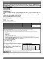
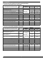
The different types of control panel are:
Control panel reference
SH320AU
SH340AU
SH380AU
Number of groups
2
4
8
Number of detectors
20
40
80
Number of user codes
32
The installation of an optional transmission module (not originally installed in the control panel) confers two additional
functions on the control panel.
Via its different communication networks, the transmission module makes the following possible:
1. remote alerts in case of intrusion or events occurring on the protected site.
• The control panel-dialler warns individual correspondents and/or a remote monitoring centre in the event of:
- intrusion,
- technical alarms,
- fire alarms,
- tamper alerts,
- faults in one of the system devices.
• In the event of intrusion, the control panel-dialler makes the following remote operations possible:
- listen-in and speak-out/talk-back,
- visual alarm confirmation via the transmission of images or films from the image transmission motion detectors
and/or compatible IP cameras installed on the protected site.
2. remote access to the protected site:
• alarm system operation,
• parameter-setting,
• checking.
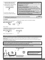
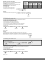
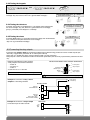
Depending on its reference, the transmission module uses
different media (see table opposite, unused media must be
declared).
When installing the product, it should be assumed that the
transmission module can have three transmission media:
PSTN, GSM/GPRS and ADSL.
RNET
/
ETHE SL)
GSM
S
D
R
(A
GP
The transmission modules are:
Module
reference
SH501AX
Transmission media
PSTN
-
SH502AX
-
GSM/GPRS
SH503AX
PSTN
GSM/GPRS
SH504AX
-
-
fi Only concerns transmission modules using the media indicated
(example here: GSM/GPRS and Ethernet (ADSL)).
2
Ethernet
(ADSL)
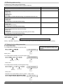
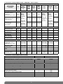
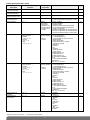
System responses:
WARNING
(((
((
((((
(
DETERRENCE
(((
(
• Control panel: 5 s audible beeps
• Telephone transmission (choice) (1)
• External siren, 3 choices possible:
- discreet sounding triggered (5 s) + strobe flashes (5 s)
- discreet sounding triggered (5 s)
- strobe flashes (5 s)
((
((((
PREALARM
((
(((
((
((((
(
• Control panel: siren triggered for 15 s + telephone transmission (choice) (1)
• External siren, 3 choices possible:
- discreet or loud sounding triggered (2) + strobe flashes (15 s)
- discreet or loud sounding triggered (15 s)
- strobe flashes (15 s)
((((
INTRUSION
(((
• Control panel: siren triggered for 90 s + telephone transmission (1)
• External siren: loud sounding + strobe flashes for 15 min.
(
I n t r u d e r a d v a n c e s f u r t h e r o n t o p re m i s e s
• Control panel: 2 s audible beeps
• External siren, 3 choices possible:
- discreet sounding triggered (2 s) + strobe flashes (5 s)
- discreet sounding triggered (2 s)
- strobe flashes (5 s)
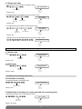
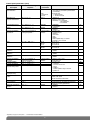
Confirmation of Intrusion alarms
Intrusion alarms can be confirmed if they are preceded by a 1st event within a specific lapse of time.
The intrusion attempt is confirmed if the intruder is detected twice leading to specific control panel messages.
Confirmation of intrusion
st
ev
t
en
1
less than 15 min
• Prealarm
nd
t
en
ev
t
en
ev less than 15 min
1
st
2
• Intrusion
• Intrusion
nd
2
• Prealarm
• Intrusion
Intrusion confirmed
Intrusion confirmed
IMPORTANT: confirmation is validated when 2 events in a row are detected by 2 different detectors.
(1) If transmission module installed.
(2) Loud triggering if Prealarm only confirmed.
3
t
en
ev
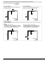
2. Preparation
2.1 Precautions to be taken into account before installing the system
2.1.1 Site diagnosis before installation
Before installing the system and deciding on the best place for each product, a diagnosis of the site to check its radio
transmission range must first be performed. It is especially important to carefully check a number of specific points
including those relating to the type of professional premises:
• distances or surfaces to be monitored: generally bigger on professional premises than residential sites,
• materials used: metallic materials are often used in walls and partitions,
• modifications to the internal configuration of the home or premises: these can be frequent (addition of walls or
furniture, storage of materials, etc.).
The range has been especially studied for all of these cases.
Nevertheless, system reliability does depend on the place where products are installed.
This is why we recommend performing a detailed survey of the site, with a focus on the following points:
• All metallic materials represent an obstacle to the propagation of radio transmissions and are likely to have a
considerable impact on the link between two products.
Thus, the following cases must be avoided:
- installation of products in the immediate vicinity of apparent or hidden metallic materials (reinforced concrete walls for
example), etc.,
- metal walls, shelves, frames or trellises between a product and the control panel or a radio repeater relay.
- installation of the control panel or a relay in a plant room or in the immediate vicinity of other electrical or computer
products.
If the above environments cannot be avoided, it is highly advisable to install a radio repeater relay to get around these
obstacles.
• Any modification to the internal configuration or layout of the home or premises is likely to have a considerable
impact on the link between two products:
- reorganisation of the premises (addition of walls or furniture, etc.),
- reorganisation of a workshop or storage area,
- storage areas with variable capacities (notably metallic materials),
- mobile metallic doors or partitions,
- parking of vehicles (handling trucks, vehicles in a garage).
In all cases where such variations are likely, it is highly advisable to use a radio repeater relay to reinforce the link and get
around potential obstacles between various products and the control panel.
We also advise you to draw users’ attention to this fact and to check the radio links again every time the configuration of the
premises is changed.
2.1.2 Checking radio links during installation
To ensure long-lasting reliability of the radio links, it is essential to check each one in Installation mode once all the products
have been installed (see chapter on “Checking the products and radio links” in this manual).
If the layout of the premises is likely to be changed, it is advisable to check products and links for every possible
configuration.
IMPORTANT: if these instructions are not complied with, random and frequent radio link losses between the various products
may be detected.
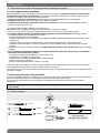
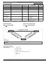
2.2 Tooling required
6 mm
PZ 2
3.5 mm
The fixing screws
and plugs are not supplied.
4
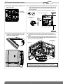
2.3 Opening the control panel
1. Remove the cover.
Cover
2. Insert a screwdriver into
the bottom right-hand side
(A) of the base and push
on it in order to open the
control panel (B).
Side view
A
B
3. Place the dialler on a flat surface and then remove the base
by inclining it an angle of 45° and pulling it downwards.
4. Guarantee sticker
Remove the pre-cut part of the guarantee
sticker and stick it to the guarantee certificate
inside the user manual supplied with the
control panel. If you are adding to an existing
system, use the guarantee certificate supplied
with this product.
45°
45°
SH380AF
D12250A7F00
SH380AF
Coller sur certif
D12250A7F00
SH380AU
D12250A7F00
SH380AU
Coller sur certif
D12250A7F00
2.4 Description
Control panel
Microphone
Three-colour LED
Loudspeaker
4 customisable command buttons:
• armed
• off
• armed partial 1
• armed partial 2
12 programming buttons
Blue light
5
LED indications
LEDs
Three-colour LED red
green
orange
Blue light
LED status
steady
continuous rapid flashing
Meaning
button pressed or line occupied
operation blocked when powered
12 s maximum rapid flashing
connection test, date and reference
1 flash every 5 s
permanent indication of test mode
2 flashes every 10 s
permanent indication of installation mode
3 rapid flashes
error
steady for 10 seconds
valid access code
steady
recording of 10 s maximum voice message
rapid flashing
during message saving (1) (no other vocal personalisation possible)
1 flash every 20 s
system fault (power fault, media fault (2) or loss of product radio link)
in user mode and when system is disarmed
modulated indication
mode change: installation, test and use
arming or disarming
system status command
one of the 4 customisable keys pressed (arm, disarm, arm partial 1 and 2)
(1) If SITE NVM stick or transmission module installed.
(2) If transmission module installed.
NC type inputs
for connecting
potential-free
conductor only
{
J2
Hardwired
detector input
Tamper
input
!
}
Control panel
relay 2 output
J6
J5
J1
Relay output:
0.5 A 24 V AC
or 1 A 30 V DC
Compartment for input/output card (optional)
Control panel
relay 1 output
Do not connect the 230 V
mains to relay outputs.
Inside view
1 x 2-point connector
for rechargeable
back-up battery
CAUTION: the system is sold without
S.I.T.E. module, it is an option and
allows:
• the storing of the parameters of all
the products of the system,
• the storing of the recorded vocal
messages.
IMPORTANT: connection and the
disconnection of the S.I.T.E module
must.
ONLY be done when the Control
panel is UNPOWERED !
Compartment for
S.I.T.E. NVM stick
(optional and not
compulsory)
Compartment
for Li-Ion rechargeable
back-up battery
(optional)
Base
Compartment:
- lithium power pack
or
- internal mains power module
(not supplied)
Slot for cable
clamp supplied in
bag of accessories
Rear view
Tamper pin
6
Detachable washer
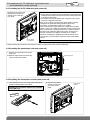
2.5 Installing the S.I.T.E. NVM stick, input/output card
and transmission module (optional)
INSTALLATION
MODE
2.5.1 Installing the S.I.T.E. NVM stick (with power off)
Insert the S.I.T.E. stick in the
appropriate compartment
making sure it is the right
way round.
The S.I.T.E. Module allows:
• saving all the parameters and personalised vocal messages and
loading this information into the Control Panel without the need
to reprogram the system.
• the transfer of the personalized vocal messages of the Control
Panel into a separate transmitter.
If the S.I.T.E. module is virgin and the power station is already
configured, the parameter setting and the programming
information is transferred into the S.I.T.E. module.
If the Control Panel is virgin and S.I.T.E. module is full, the data
stored in the S.I.T.E. module is transferred into the Control Panel.
If the Control Panel is configured and S.I.T.E. module is also full,
and the 2 sets of data are different the system announces an
anomaly, and start-up is delayed until the S.I.T.E. module
becomes compatible by updating itself with the data from the
Control Panel. The assumption is that the Control Panel data is
correct.
S.I.T.E. module
compartment
CAUTION: the transfer time of the data can be long.
If using an input/output card and a transmission module, the input/output card must be installed first.
2.5.2 Installing the input/output card (with power off)
1. Position the input/output card on the
guide rails.
2. Slide the input/output card to the top
until it is locked into position.
Input/output card
Guide rails
2.5.3 Installing the transmission module (with power off)
1. Insert the SIM card into its compartment following the
direction indicated below the module.
2. Clip the transmission
module on to the top
part of the control
panel.
IMPORTANT: the transmission module is only compatible
with mini SIM cards.
S
/GPR
GSM
7
Transmission
module
INSTALLATION
MODE
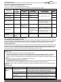
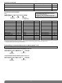
2.6 Power supply
Type of power supply to be installed according to media used:
• 2 x (3.6 v, 13 Ah) lithium power pack, BatLi 22
• Li-Ion = 3.7 V/1.2 Ah Li-Ion rechargeable back-up battery
• Mains power module = 200-240 VAC 50-60 Hz / 4.5 VDC 2.2 A internal mains power module
Control panel
without
transmission
module
Media used
PSTN+Ethernet
(ADSL)
GSM/GPRS+
Ethernet (ADSL)
PSTN+GSM/GPRS
+Ethernet (ADSL)
/
/
Control panel with telephone transmission module/media available
SH501AX
SH502AX
SH503AX
SH504AX
PSTN+ Ethernet
GSM/GPRS+
PSTN+GSM/GPRS+
Ethernet
(ADSL)
Ethernet (ADSL)
Ethernet (ADSL)
(ADSL)
mains power
/
/
module + Li-Ion
mains power module
/
mains power module + Li-Ion
/
+ Li-Ion
/
/
/
(PSTN+GSM/GPRS)
only
/
/
PSTN only
/
• BatLi 22
or
• mains power
module + Li-Ion
GSM/GPRS only
/
/
BatLi 22
No remote
mains power
transmission module or
module
/
/
/
• BatLi 22 + compulsory Li-Ion
or
• mains power module + Li-Ion
for GSM incoming calls
/
/
• BatLi 22
or
• mains power module + Li-Ion
/
• BatLi 22 +
• BatLi 22 + compulsory Li-Ion
compulsory Li-Ion
or
or
mains power module + Li-Ion
• mains power module • for
GSM incoming calls
+ Li-Ion
/
Ethernet (ADSL) only
mains power module + Li-Ion
/
/
/
/
When using the transmission module card:
Accessories and power supplies to be used
The accessories and power supply(ies) needed to install the control panel-dialler depend on the type of transmission module and
media used. Before going out to the site, installers must make sure they have the additional accessories and power supply(ies)
listed in the “Appendix” chapter (besides any accessories that are supplied with control panel and transmission module).
Declaring unused media
To prevent faults from occurring due to line cuts or the absence of transmission media in user mode, unused media must be
declared. This parameter-setting operation is explained in the installation manual common to the control panel-dialler and
the stand-alone dialler: “Parameter-setting and implementation of transmission with transmission module/chapter on
“Main parameter-setting operations for the transmission module/Declaring unused media”.
Indication of power faults on power-up
Please note:
• If the main power supply has to come from the mains power module:
- a sufficiently charged Li-Ion back-up battery must be installed in case the control panel-dialler issues the voice message
“Fault, Accumulator Voltage, Control panel”, and the red LED flashes until the battery has been properly connected.
- if there is a mains power supply problem, the control-panel dialler issues the voice message “Fault, Battery Voltage, Control
panel”.
• If the main power supply comes from the BatLi22 lithium power pack:
- the Ethernet (ADSL) media will not be operational,
- the GSM/GPRS media will be operational on condition that the Li-Ion back-up battery has been installed. In this case
(powered without mains), the GSM/GPRS media will be configured by default for outgoing calls only.
If an improper power supply is used with the transmission module connected this will lead to an error indication following
power-up.
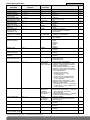
What to do if?
Red LED
Voice message
Solutions
Constant
rapid
flashing
“fault, power supply,
transmitter plug”
use the tables in the “Appendix/Accessories and power supplies to
be used” chapter to check compatibility between the transmission
module media and the control panel-dialler power supply.
“fault, transmitter plug”
check the transmission module has been properly installed.
“fault, battery voltage,
control panel”
check the state of the main power supply: BatLi 22 lithium power
pack or mains power module depending on the case.
“fault, accumulator
voltage, control panel”
if the power supply is from the mains, check that the Li-Ion back-up
battery has been installed and is properly charged.
8
IMPORTANT
• Use of the back-up battery is often compulsory for operation with a transmission module (see chapter 2.6 Power supply).
• the back-up battery is recharged on the control panel and is designed to back up the main power supply.
• Connect the back-up battery before the lithium power pack or internal mains power module.
• The back-up battery must be connected with the power off.
2.6.1 When using the lithium power pack (supplied)
1. Position the lithium power pack on
the guide rails.
2. Slide the lithium power pack to the
top until it locks into position.
3. After power-up you will hear the
control panel voice message:
IMPORTANT
• If the dialler does not respond as it
should:
- disconnect the lithium power pack
and then the back-up battery,
- wait for 2 min,
- reconnect the back-up battery
and then the lithium power pack,
- check the correct voice message
is issued.
If there is a problem, the control
panel will issue the following
message: “Fault, battery voltage,
control panel”.
• On power-up, the control panel is
automatically in installation mode.
“bip, installation mode”
Locking key
To remove the lithium power pack,
press on the unlocking key and slide
it downwards.
2.6.2 When using the BatLi 22 lithium power pack and the Li-Ion rechargeable back-up battery
1. Connect the rechargeable back-up battery
to the 2-point connector.
2. Clip the back-up battery into its compartment.
2-point
connector
3.7 V/1.2 Ah
back-up
battery
3. Position the lithium power pack on
the guide rails.
4. Slide the lithium power pack to the
top until it locks into position.
5. After power-up you will hear the
control panel voice message:
IMPORTANT
• If the dialler does not respond as it
should:
- disconnect the lithium power pack
and then the back-up battery,
- wait for 2 min,
- reconnect the back-up battery
and then the lithium power pack,
- check the correct voice message
is issued.
If there is a problem, the control
panel will issue one of the fault
messages (see Indication of power
faults on power-up on previous
page).
• On power-up, the control panel is
automatically in installation mode.
“bip, installation mode”
Locking key
To remove the lithium power pack, press on the unlocking key and slide it downwards.
9
2.6.3 When using with the mains power module and Li-ion rechargeable battery (not supplied)
1. Connect the rechargeable back-up battery
to the 2-point connector.
2. Clip the back-up battery into its compartment.
2-point
connector
Battery
3. Loosen the internal mains power
module locking screw.
Locking screw
4. • Connect the mains power cable type H05VVF 2 x 0.75 mm2,
twin with diameter between 5 mm and 7.5 mm to the terminal block.
• Install a cable clamp.
• Put the cover back and tighten the closing screw.
Strip 28 mm of the outer cover, and 7 mm of insulation
from the inner cores
Connect to terminal “N”
of the terminal block
(blue cable)
Connect to terminal “L”
of the terminal block
7 mm +/-1
Cover
28 mm +/-2
IMPORTANT: only use 4.5 V DC
power module
230 V
mains cable
clamp (not
supplied)
RXU01X internal mains power module:
200-240 VAC
50-60 Hz / 4.5 VDC 2.2 A
double insulation symbol,
220 V power supply
without earth connection)
Terminal N
Terminal L
5. Position the mains power module on the guide rails.
6. Slide the module upwards until it locks into position.
Locking key
10
Electrical
shock hazard
7. Connect the other end of the mains
cable to the mains power via an
unswitched fused connection box.
8. Following power up, the control panel
will issue the voice message:
IMPORTANT
• If the control panel does not respond as it should:
- disconnect the mains power supply then disconnect the power module,
- disconnect the back-up battery,
- wait for 2 min,
- reconnect the back-up battery,
- reconnect the power module and then the mains power supply,
- check the control panel message.
• On power-up, the control panel is automatically in installation mode:
- if the battery is not detected, the control panel issues the voice message
“fault, accumulator voltage, control panel”, and the red LED flashes until
the battery has been properly connected,
- if there is a mains power supply problem, the control-panel issues the
voice message “fault, battery voltage, control panel”,
- if using the Mains power supply (RX01X) and requiring to change the type
of power supply (BatLi22) this MUST be done totally UNPOWERED. It is
IMPERATIVE to disconnect the standby battery (Li-Ion 3.7 V/1.2 AH) and
wait for 2 minutes before re-connecting power.
“bip, installation mode”
To remove the module, press the
unlocking key and slide it downwards.
2.7 Modifying the language and modifying the volume of indications
and speech synthesis system
ION
INSTALLAT
MODE
• Language
Depending on the user, you can replace the original system language, English, with a different language:
To select the language, programme:
“bip + chosen
language”
0: French
1: Italian
2: German
3: Spanish
4: Dutch
5: English
Factory: English
• Setting the indication and speech synthesis volume
The level can be adjusted from 1 to 8.
“bip + chosen level”
Sound level from 1 to 8
Factory: average sound level = 4
3. Recognition programming
Recognition programming makes it possible for a product (remote control unit, detector, etc.) to be recognised by the control
panel. The control panel allocates a number to each product programmed for recognition in chronological order of
programming.
For products that need to be relayed, control panel recognition programming must be done via a radio repeater relay (see
Radio repeater relay installation manual).
IMPORTANT
• To perform recognition programming operations, the control panel must be in installation mode.
• During recognition programming, the product to be programmed for recognition does not need to be close to the control
panel. In fact, it is advisable to move it at least 2 metres away from the control panel.
3.1 Programming a remote control unit to be recognised by the control panel
“Bip, remote control unit X”
)))
))
IMPORTANT: the control panel issues three
short beeps to indicate a programming error.
When this happens, perform recognition
programming again from the start.
then
10 s max.
Press * then # on
the control panel
keypad
Press and hold “Off”
(orange LED flashing)
until the control panel
responds
The control panel issues a voice
message and the remote control
unit LED lights up steady green
for 1.5 s to confirm recognition
11
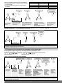
3.2 Programming an intrusion detector to be recognised by the control panel
Different types of triggering possible: • immediate,
• time-delayed,
• combined.
Time-delayed triggering
In the event of intrusion, the alerts and deterrents are
triggered at the end of the entrance time delay.
Immediate triggering
In the event of intrusion, the alerts and deterrents are
immediately triggered.
door
door
keypad
Door/window detector 1
GR1 immediate
Door/window detector 1
GR1 time-delayed
keypad
window
window
Motion detector 2
GR1 immediate
Motion detector 2
GR1 time-delayed
Combined triggering
A combined detector is immediately triggered if it is activated first. Its triggering is time-delayed if another time-delayed
detector is activated first.
Example:
• The user enters his/her home:
Door/window detector 1 is activated and motion
detector 2 becomes time-delayed hence allowing the
user to reach the keypad to disarm the system.
• In the event of intrusion via the window:
Door/window detector 1 is not activated, motion
detector 2 triggering becomes immediate and the
alerts and deterrents are immediately triggered.
door
door
Door/window detector 1
GR 1 time-delayed
Door/window detector 1
GR 1 time-delayed
keypad
keypad
window
window
Motion detector 2
GR1 combined
Motion detector 2
GR1 combined
12
Detector recognition programming involves selecting:
• a protection group from 1 to 8 (according to the type
of control panel),
• the type of triggering (immediate, time-delayed or
combined).
“detector X”
Control panel reference
Number of groups
Number of detectors
SH320AU
2
20
SH340AU
4
40
SH380AU
8
80
“group?”
“bip, detector X,
group Y, immediate
(or time-delayed
or combined)”
“time delay ?”
))
)))
or
)))
))
then
to
to
10 s max.
Press and hold the “test”
button until the control
panel responds
Press * then # on
the control panel
keypad
Select a group from 1 to 8*
(see table). Press the control
panel keypad to make the
selection.
Choose the type of triggering:
0: immediate • 1: time-delayed
2: combined
Press the control panel keypad to
make the selection
The control panel issues a
voice message to confirm
detector recognition
programming.
Example: programming 1st door/widow detector, allocated to group 2 and set for immediate triggering. The control panel
automatically allocates n° 1 to the first detector programmed.
“detector X”
“group?”
“bip, detector 1,
group 2,
immediate”
“time delay ?”
)))
))
then
10 s max.
IMPORTANT: the control panel issues three short beeps to indicate a programming error. When this happens, perform
recognition programming again from the start.
3.3 Programming the keypads to be recognised by the control panel
For recognition programming to work, the keypad must be in installation mode.
On power-up, the keypad is in user mode. To put it in installation mode, use the keypad to enter:
then
master code (factory: 0000)
installer code (factory: 1111)
• With a vocal keypad with tag reader SH640AX:
“bip, remote control
unit X, bip, detector X”
“group?”
“time delay?”
to
to
“bip, remote control
unit X, bip,
detector X, group Y
(immediate, timedelayed or combined)
“bip”
)))
))
puis
10 s max.
Press * then #
on the control
panel keypad
Press and hold
the “Off” button
until the control
panel responds
The control
panel issues a
voice message
to confirm
keypad
recognition
programming
The control panel
waits to know the
infrared detector
group (from 1 to 8
according to the
type of control
panel). Press the
control panel keypad
to select the group.
The control panel waits to
know the chosen triggering
type for the infrared detector:
0: immediate,
1: time-delayed,
2: combined.
Press the control panel
keypad to make the
selection
The control
panel issues a
voice message
to confirm
infrared
detector
recognition
programming
The keypad
issues a long
beep to
confirm
recognition
programming
IMPORTANT: the control panel issues 3 short beeps to indicate a programming error. When this happens, perform recognition
programming again from the start.
13
• With an information and command keypad SH630AX:
“bip, remote control unit X”
“beeep”
)))
))
then
10 s max.
Press and hold “Off” until the control
panel responds
Press * then # on the
control panel keypad
The control panel issues a voice
message to confirm keypad recognition
The keypad issues a long beep to
confirm recognition programming
IMPORTANT: the control panel issues 3 short beeps to indicate a programming error. When this happens, perform recognition
programming again from the start.
3.4 Programming a control panel with the siren
When powered, the siren is in installation mode
“bip”
“bip”
or
“bip, Off,
control panel”
))
“beeep”
)))
))
“bip, siren n°”
)))
or
10 s max.
Briefly press the siren
“test” button.
Press and hold “Off”
until the control panel
responds
The siren issues an
audible signal to confirm
recognition programming
The control panel
specifies the siren n°
IMPORTANT: the control panel issues 3 short beeps to indicate a programming error. When this happens, perform recognition
programming again from the start.
3.5 Checking recognition programming
When checking programmed products, the control panel issues voice messages in the following order:
• remote control units,
• detectors,
• sirens,
• diallers,
• radio repeater relays or receivers.
To check all programmed products, use the control panel keypad to enter:
Example of check:
“bip, remote control unit 1,
bip, remote control unit 2,
bip, detector 1, group 2 immediate,
bip, siren 1”
14
3.6 Deleting a programmed product
The control panel recognises 5 types of product according to their number.
Type of product
Detector
Remote control unit
Siren
Dialler
Radio repeater relay or receiver
Number
2
3
4
5
7
To delete a programmed product, enter:
type of product
product n°
Example:
To delete the 2nd programmed siren, enter:
IMPORTANT:
• If a radio repeater relay is deleted, all relayed products are not automatically deleted. Each product must be deleted from the
control panel.
- To delete a keypad, proceed as follows:
• put the system in installation mode using the KEYPAD to enter:
then
master code
installer code
2. USING THE CONTROL PANEL, enter:
keypad n°
3.7 Deleting all recognition programming
To delete all programmed products, enter:
“beeep”
press
and hold
15
4. Changing operating modes
The operating mode is changed using the factory master code “0000” then the factory installer code “1111” as shown
below:
installer code
INSTALLATION
MODE
USER MODE
2 flashes
every 10 s
ins
tal
ler
ins
tal
ler
co
de
co
de
e
od
rc
e
t
s
ma
e
od
rc
ste
a
m
TEST MODE
1 flash every 5 s
IMPORTANT: for security reasons, the control panel automatically switches back to user mode after 4 hours without a
command being issued.
The control panel keypad or command keypad can be used to check the mode.
Operating mode
Keypad sequence
system status, installation mode and any faults
e.g. “bip, system status, installation mode”
INSTALLATION
MODE
system status, test mode and any faults
e.g. “bip, system status, test mode”
TEST MODE
USER MODE
Message
master code
system status (disarming and any faults)
e.g. “bip, system status, off”
5. Main parameter-setting operations
IMPORTANT: all parameter-setting must be performed using TwinLoad® software available in the Installers section at
www.daitem.co.uk.
5.1 Modifying access codes
If the system has a command keypad, any modifications to the control panel must be repeated on the command keypad.
To ensure system confidentiality, access codes must be modified:
• the master code for use by the user,
• the installer code.
N
TIO
LA
AL DE
T
INS MO
The master code can be modified in the 3 operating modes:
16
or
DE
MO
ST
E
T
or
DE
MO
ER
S
U
Number of access code digits
Factory code
Number
of digits
Before modifying access codes, the number of access
code digits must first be determined.
This modification must be done using the factory code.
Extending the number of digits applies to:
• the master code,
• the installer code,
• the remote monitoring centre code.
4 (factory)
1111
0000
remote
monitoring
centre
2222
5
11111
00000
22222
6
111111
000000
222222
installer
To modify the number of digits, enter:
number of digits (from 4 to 6)
Example:
To extend access codes to 6 digits, enter:
“bip, 6”
5.2 Modifying the master code
The master code is designed for the main user and allows the following:
• complete use of the system (all commands),
• access to TEST mode and USER mode,
• remote operation of the system over the phone,
• control (authorisation or inhibition) of User codes,
• control of access to remote management and remote configuration.
To ensure system confidentiality, access codes must be modified.
To do this, enter:
old
master code
new
master code
new
master code
Factory: 0000
Example:
To replace the factory master code “0000” with the new code “1234”, enter:
“beeep”
5.3 Modifying the installer code
Before modifying the installer code, check that the control panel is in installation mode.
To do this, proceed as follows:
ION
AT
LL
TA ODE
S
IN M
then
master code
installer code
The installer code is for use by the installer.
It allows access to system installation, programming and maintenance operations:
• INSTALLATION MODE access,
• remote configuration.
To ensure system confidentiality, the installer code must be modified.
To do this, proceed as follows:
old installer
code
new code
installateur
new code
installateur
Factory: 1111
17
master
Example:
To replace the factory installer code “1111” with the new code “5678”, proceed as follows:
“beeep”
5.4 Modifying the remote monitoring centre code (if transmission module installed)
• Modifying the remote monitoring centre code
To modify the remote monitoring centre code, proceed as follows:
“beeep”
old remote monitoring
centre code
new remote monitoring
centre code
new remote monitoring
centre code
Factory: 2222
5.5 Setting the date and time parameters
5.5.1 Date
The events memorised by the control panel are time and date-stamped. If an alarm is triggered or a fault occurs, this
facilitates diagnosis.
To programme the date, enter:
“bip + date
announced”
day
month
year
(for 2012, enter 12)
Example:
To programme the 13th April 2012, enter:
“bip, 13/4/2012”
To check the date, enter:
“bip, 13/4/2012”
5.5.2 Time
Enter:
“bip + time
announced”
hours
minutes
Example:
To programme 11:07 AM, enter:
“bip, 11:07”
To check the time, enter
“bip, 11:07”
18
IMPORTANT
• The date and time must be
reprogrammed if the power
supply is disconnected.
• The switch between summer
and winter time is automatic.
5.6 Blocking system arming
If a fault occurs, system arming can be blocked.
The control panel can be programmed for 5 types of response.
Response
Value
arming blocked disabled
0
arming blocked if at least one of the following faults occurs:
• power fault
• tamper fault
• radio link fault
• exits open
It is possible to override blocked arming: 4 commands in less than 10 s.
1
arming blocked if at least one of the following faults occurs:
• tamper fault,
• exit(s) open
It is impossible to override blocked arming.
2
blocked if supervision command not received within 20 min:
• tamper fault
• exit(s) open upon arming
It is impossible to override blocked arming.
3
blocked if supervision command not received within 20 min and exits checked
upon arming and at the end of the exit time delay:
• tamper fault
• exit(s) open
• management of open exits upon arming and during exit time delay.
It is impossible to override blocked arming.
4
To activate blocked system arming, enter:
IMPORTANT: the control panel issues 3 short beeps to indicate errors.
from 0 to 4
Factory: 4 (blocked if supervision command not received (20 min) and exits checked at the end of the exit time delay)
5.7 Setting the time delay parameters
5.7.1 Exit time delay
NOTE: when arming several Groups with
time delays, the longest time delay will be
effective.
• To modify the exit time delay on all groups, enter:
“bip + value entered”
from 0 to 90 s
Factory: 90 s.
• To modify the exit time delay on one of the groups, enter:
“bip + value entered”
group n° from 0 to 90 s
from 1 to 8
Factory: 90 s.
• To modify the exit time delay on several groups, enter:
...
group n°
from 1 to 8
“bip + value entered”
from 0 to 90 s
Factory: 90 s.
Example: for an exit time delay of 40 s for groups 1, 4 and 6, enter:
“bip, 1, 4, 6, 40”
19
5.7.2 Entry time delay
• To modify the entry time delay on all groups, enter:
“bip + value entered”
from 0 to 90 s
Factory: 20 s.
• To modify the entry time delay on one of the groups, enter:
“bip + group X
+ value entered”
group n°
from 1 to 8
from 0 to 90 s
Factory: 20 s.
• To modify the entry time delay on several groups, enter:
...
“bip + groups
+ value entered”
group n°
from 1 to 8
from 0 to 90 s
Factory: 20 s.
Example: for an entry time delay of 30 s for groups 2, 3 and 7, enter:
“bip, groups 2, 3, 7, 30”
IMPORTANT: when several groups are armed, it is the longest time delay that is taken into account.
5.7.3 Entry route
“beep + announcement
of digits entered"
Enter:
0: disabled
1: enabled
Factory: actif
5.7.4 Exit route
“beep + announcement
of digits entered"
Enter:
0: disabled
1: enabled
Factory: inactif
5.8 Setting the sounding parameters
5.8.1 Duration of sounding
To modify the duration of sounding, enter:
“bip + value entered”
from 20 to 180 s
Factory: 90 s.
5.8.2 Allocation of sounding to a control panel with one or several groups
To allocate sounding to one or several groups, enter:
...
“bip + groups”
group n°
from 1 to 8
Factory: all groups
20
5.9 Vocal personalisation
5.9.1 Vocal personalisation of products (40 max)
In order to identify products more easily, a personalised voice message lasting 3 s maximum can be recorded.
To record the message, enter:
“message recorded”
product n°
from 01 to 80
product
type n°
Product type
Number
Hardwired input
0
Detector
2
Remote control unit
3
Siren
4
Dialler
5
Radio repeater
relay or receiver
7
wait for the
green LED
on the control
panel to light
up before
speaking into
the microphone
“message announced”
speak in front
of the
microphone
Control panel ref.
Number of detectors
SH320AU
20
SH340AU
40
SH380AU
80
Example of personalised message: detector 4 in “entrance hall”, enter:
“entrance hall”
“entrance hall”
x
To check the identification message, enter:
“entrance hall”
5.9.2 Vocal personalisation of groups (1 to 8 groups according to the control panel)
In order to identify groups more easily, it is possible to record a personalised voice message lasting 3 s maximum.
To record the message, enter:
“message recorded”
group n°
wait for the
green LED
on the control
panel to light
up before
speaking into
the microphone
Control panel ref.
Number of groups
SH320AU
2
SH340AU
4
SH380AU
8
“message announced”
speak in front
of the
microphone
Example of personalised message: group 2 on “1st floor”, enter:
“1st floor”
“1st floor”
x
To check the identification message, enter:
“1st floor”
21
5.10 Stopping the exit time delay when the last exit is closed
It is possible to automatically programme the exit time delay to end when the last exit is closed by determining the
door/window detector that will arm one, several or all groups.
The exit time delay will be stopped as soon as the door where the detector is installed is closed.
IMPORTANT
- This function can be programmed on 8 door/window detectors maximum.
- The chosen detector must be allocated to one of the groups selected.
• To programme ending of the exit time delay on one or several groups, enter:
...
detector n°
from 1 to 80
Control panel ref.
Number of groups
SH320AU
2
SH340AU
4
SH380AU
8
n° of group
or groups
from 1 to 8
Example: to stop the exit time delay for groups 2 and 4 when detector 11 exit is closed, enter:
“bip, 11, bip, 2, 4”
• To programme ending of the exit time delay for all groups, enter:
“bip, n° détecteur,
bip, 1, 2... 8”
detector n°
from 1 to 80
INSTALLATION
MODE
6. Advanced parameter-setting operations
Modifying user codes
IMPORTANT: the user codes are not programmed in the factory configuration.
The user codes are for occasional users (service personnel, employees, etc.).
They are for limited and temporary use of the system:
• access restrictions to some commands or some groups can be programmed for each user code,
• each user code can be authorised or disabled at any time.
The control panel has 32 user codes.
To programme or modify a user code, enter:
master code
from 1 to 32
(chosen user code)
user code
IMPORTANT
• A long beep is issued to confirm
programming.
• 3 beeps are issued to indicate
a programming error.
user code
Example: using the master code “1234”, programme user code 1 “1213”
Restricted access of user codes
User codes can have separate and limited access to:
• certain command buttons,
• certain groups.
Only the commands or groups programmed can be accessed when the user code is entered.
When access is restricted to certain buttons, the group disarming and arming commands remain accessible.
• Restricted access to certain command buttons
...
master code
from 1 to 32
(chosen user code)
user code
user code
command
button/s
Example: to restrict user code 1 to the Armed Partial 1 command, enter:
Armed Partial 1 button
In this case, only the Armed Partial 1 button can be accessed via user code 1.
22
• Access restricted to certain groups
...
master code
from 1 to 32
(chosen user code)
user code
user code
group 1 to 8 buttons
(according to type of control
panel)
Example: to restrict user code 1 to Group 1, enter:
Group 1 button
In this case, only the Disarmed or Armed Group 1 button can be accessed via user code 1.
• Combined restricted access to certain command buttons and certain groups
...
master code
from 1 to 32
(chosen user code)
user code
group 1 to 8 buttons
(according to type of control panel)
user code
repeated
command button/s
Disabling or authorising a user code
A user code can be authorised or disabled in the 3 operating modes.
A programmed user code is automatically authorised.
To disable or authorise a user code, enter:
master code
from 1 to 32
(chosen user code)
0: unauthorised
1: authorised
Examples:
• To disable user code 1, enter
• To authorise user code 1, enter:
Personalising a command button
The 4 command buttons on the control panel can be personalised to adapt the commands to the user’s needs (see table
below). Furthermore, this personalisation allows the user to select the type of access required to these commands (direct or
via a code).
To personalise a button, enter:
IMPORTANT
button to be
personalised
command number
(see table
on next page)
type of access:
0: direct access
1: code-based
• In installation mode, the keypad commands can be accessed
directly.
• All disarming and arming commands as well as the system status
command can only be accessed via a code.
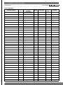
Personalised commands
Command description
Command n°
Command description
Command n°
Command description
Command n°
Disarm (1)
21
Off light
52
On relay 3
Alert
22
On light
54
Relay 3 toggle switch
86
Arm (1)
23
Light toggle switch
56
Relay 3 timer
88
Silent alarm
24
Light timer
58
Off relay 4
92
Partially arm 1 (1)
25
Off relay 1
62
On relay 4
94
Partially arm 2 (1)
27
On relay 1
64
Relay 4 toggle switch
96
Fire alarm
32
Relay 1 toggle switch
66
Relay 4 timer
98
Arm presence
33
Relay 1 timer
68
Off relay control panel 1
112
Silent command
36
Off relay 2
72
On relay control panel 1
114
Stop indications (1) (2)
37
On relay 2
74
Off relay control panel 2
122
Chime
38
Relay 2 toggle switch
76
On relay control panel 2
124
Audible signal
42
Relay 2 timer
78
System status (1)
129
No command
44
Off relay 3
82
(1) Command with code access only.
(2) Used to stop indications concerning a technical alarm, an alert or a tamper alarm without changing the system status.
Important: telephone transmissions are not interrupted.
Example: to personalise the
buttons as an “Alert” with code-based access, enter:
23
84
Personalising a command button to arm or disarm groups 1 to 8
IMPORTANT: all disarm or arm commands can only be accessed via a code.
• To personalise a button so that it arms groups 1 to 8, enter:
...
button to be
personalised
group(s) 1 to 8
Example: to personalise the
button to arm groups 5 and 6:
• To personalise a button to disarm groups 1 to 8, enter:
...
buttonto be
personalised
group(s) 1 to 8
Example: to personalise the
button to disarm groups 7 and 8:
Delayed sounding
To modify delayed sounding, enter:
“bip + value entered”
from 0 to 60 s
Factory-set sounding: 0 s, immediate
Manager reset
When an intrusion is confirmed, activating the manager reset parameter blocks system rearming.
Only the installer can unblock the system using the general reset authorisation command on the control panel keypad.
To unblock the system, enter:
installer code
To activate this parameter, enter:
0: disabled
1: enabled
Factory: disabled
Activation of the built-in siren upon intrusion
To modify siren triggering, enter:
“bip + value entered”
0: disabled
1: enabled
Factory: enabled
Allocation of a detector programmed for recognition
The allocation of a detector programmed for recognition can be modified using the control panel keypad during product
recognition programming:
• groups 1 to 8 (according to the type of control panel),
• type of triggering (immediate, time-delayed or combined).
To modify a detector’s allocation, enter:
...
programmed
detector n°
group(s)
1 to 8
0: immediate
1: time-delayed
2: combined
24
Type of indication
To modify the type of indication, enter:
• For warning:
• For deterrence:
0: disabled
1: sounding (2 s)
• For prealarm:
0: disabled
1: sounding (5 s)
25
Factory: sounding (2 s)
Factory: sounding (5 s)
0: disabled
1: sounding (loud for 15 s)
Factory: sounding (loud for 15 s)
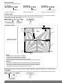
Common group
A common group can be programmed on the control panel and associated with other groups. This makes it possible to
disarm and arm the system automatically depending on the state of the associated groups.
To programme a common group, enter:
“bip, chosen group,
n° of groups”
...
chosen common group from
among 8 groups (according
to type of control panel)
groups from 1 to 8
(chosen associated
groups)
Application example:
Groups 2, 3 and 4 are
associated with group 1
{
motion
detector 2
motion
detector 1
hall
window
keypad
common
group 1
office 1
window
group 2
control
panel
office 2
office 3
group 3
group 4
motion
detector 3
window
motion
detector 4
window
• Arming:
- when group 2 is armed: office 1 is protected,
- when group 3 is armed: office 2 is protected,
- when group 4 is armed: office 3 is protected,
- when the common group is armed: the hall is protected,
when the 3 groups (2, 3 and 4) are armed, the common group/hall is also armed.
• Disarming:
- when group 2 is disarmed: office 1 and the hall (common group) are disarmed,
- when group 3 is disarmed: office 2 and the hall (common group) are disarmed,
- when group 4 is disarmed: office 3 and the hall (common group) are disarmed,
- when the common group is disarmed: the hall is disarmed.
Selecting groups to be associated with Armed Partial One, Armed Partial Two or Armed Presence
commands
To select the active groups associated with Armed Partial One, Armed Partial Two or Armed Presence commands, enter:
...
“bip, group n°”
group(s) from 1 to 8
1: Armed Partial One
2: Armed Partial Two
3: Armed Presence
25
Uninhibitable detector
If an exit is still open when the system is armed or a detector abnormally and repeatedly triggers, the control panel
automatically inhibits the detector concerned.
To delete this automatic inhibition, enter:
“bip, detector X,
0 or 1”
programmed
detector n°
0: inhibitable
1: uninhibitable
Factory: inhibitable
Type of command indications
To modify the type of indication, enter:
0: disabled indication
1: vocal indication
IMPORTANT: whatever the type of indication chosen, the speech synthesis
system is temporarily reactivated to indicate possible alarms or faults.
Factory: vocal
“Protection active” indication
The control panel indicates that the system is armed by issuing a series of 4 beeps and the message “Protection active”.
The user has the entry time delay to disarm the system before the alarms are triggered.
To modify this indication, enter:
0: disabled
1: enabled
Factory: enabled
Media fault indications
If the PSTN or GSM network is cut off, the control panel can trigger an alarm and a call via the back-up media. The system’s
response depends on the duration of the cut (more than 1 or 15 min).
0: events log alarm memorisation + vocal indication
1: events log alarm memorisation + vocal indication + fault message transmission if back-up media present
2: events log alarm memorisation + vocal indication + fault message transmission if back-up media present
+ start of alarm confirmation duration +
- if the system is totally armed and the PSTN is cut off > 1 min fi 15 s triggering
- if the system is totally armed and the PSTN is cut off > 15 min or GSM is cut off fi 90 s triggering
3: events log alarm memorisation + vocal indication + fault message transmission if back-up media present +
- if PSTN cut off > 1 min fi 15 s triggering
- if PSTN cut off > 15 min or GSM cut off fi 90 s triggering
Factory: events log alarm memorisation + vocal memorisation
Behaviour of system components in relation to the value of parameter 26 (detection of communication network cut)
Control panel and control panel-dialler
0
1
2
events log alarm memorisation
+ vocal indication
Internal and external siren
0
no response
0
1
1
if back-up media is present,
transmission of stand-alone dialler
media loss and restoral alarms only
2
no response
in the event of a fault
and whatever the value
of parameter 26
events log alarm memorisation
+ vocal indication + fault message transmission
if back-up media present
events log alarm memorisation
+ vocal indication + fault message transmission
if back-up media present
+ if system is totally armed:
if PSTN cut > 1 min
15 s triggering
3
Stand-alone dialler
0
0
no response
1
loud sounding
if totally armed
2
loud sounding
24/24
no response
if PSTN cut or GSM
interference > 15 min
90 s triggering
events log alarm memorisation
+ vocal indication + fault message transmission
if back-up media present
+ whatever the system status:
if PSTN cut > 1 min
if PSTN cut or GSM
interference > 15 min
15 s triggering
90 s triggering
1
transmission of system media
loss and restoral alarms
26
Example 1:
Parameter 26 on the control panel is set at 0. Whatever the configuration of the other devices and the duration of the media
cut, the event will only be memorised in the events log and indicated vocally.
Exemple 2:
Parameter 26 is set at 2 on the control panel, at 1 on the dialler and at 1 on the internal and external sirens.
• If the system is totally armed and the PSTN media cut (or GSM interference) lasts longer than 1 minute:
- the control panel will memorise the event in the events log, provide vocal indication of the event, transmit the fault
message if back-up media is available and trigger the siren,
- the stand-alone dialler will use the back-up media to transmit the media loss followed by the media restoral (when it
becomes available again),
- the sirens will trigger loudly.
• If the system is disarmed or one or several groups are disarmed:
- the control panel will memorise the event in the events log, provide vocal indication of the event and transmit the fault
message if back-up media is available,
- the stand-alone dialler will transmit the media loss followed by the media restoral (when it becomes available again),
- the siren will not respond.
Radio fault indications
To modify the control panel indication level in the event of faults, enter:
“bip, n° ?”
0: indication disabled
1: indication and telephone transmission (1)
2: local indication
Factory: indication and telephone transmission (1)
Radio tamper
The control panel monitors the availability of radio links. If the radio links are tampered with, the control panel can trigger an
alarm (loud sounding for 90 s).
To modify radio tamper alarm triggering, enter:
0: disabled
1: enabled 24/24 (transmission (1) + indication + events log alarm memorisation + alarm triggering)
2: enabled 24/24 (transmission (1) + indication + events log alarm memorisation)
Factory: enabled 24/24 (transmission (1) + indication + events log alarm memorisation)
Management of tamper alarms in installation mode
If one of the system products triggers a tamper alarm, the control panel can activate:
• a telephone transmission (1),
• the relay outputs (if programmed for “all alarms” (2)),
• memorisation in the events log.
To modify this configuration, enter:
(1) If transmission module installed.
(2) If input/output card connected.
0: disabled, no triggering
1: enabled, triggering of tamper alarm
Factory: enabled
Programming connected inputs and outputs (if input/output card connected)
A. Programming hardwired inputs
The hardwired input can be programmed according to the control panel response required.
To set this parameter, use the control panel keypad and proceed as follows:
“bip + selected option”
Type of input
• 0: disabled
• 1: exit
• 2: intrusion
• 3: deterrence
• 4: prealarm
• 5: fire
• 6: technical
• 7: emergency call
• 8: alert
• 9: silent alarm
• 10: chime
Factory: 2 (intrusion)
27
If the hardwired input is configured for an exit, intrusion, deterrence or prealarm, it is factory allocated to group 1 set for
immediate triggering.
To modify this allocation, enter:
...
groups
1 to 8
0: immediate
1: time-delayed
2: combined
Factory: hardwired input allocated to group 1 set for immediate triggering
B. Programming the relay outputs
The control panel has 2 relay outputs.
Each relay can be programmed according to the type of alarm concerned.
To perform this programming, enter:
• Programming a bistable relay:
6: relay 1
7: relay 2
Appearance or disappearance event
• 0: manual (upon keypad or radio command)
• 1: single intrusion
• 2: confirmed intrusion
• 3: confirmed intrusion
(+ tamper and alert command)
• 4: deterrence
• 5: prealarm
• 6: fire
• 7: technical
• 8: system disarmed
• 9: system armed
• 10: PSTN network cut
• 11: GSM network cut
• 12: ADSL network cut
• 13: main dialler unavailable
• 14: all
appearance disappearance
event
event (see table
(see table opposite)
opposite)
• Programming an impulse relay (0.5 s relay activation):
6: relay 1
7: relay 2
appearance event
(see table opposite)
• Programming a timer relay:
6: relay 1
7: relay 2
appearance
event (see table
opposite)
from 1 to 120 s
Blue light indication
To activate or deactivate the control panel blue light, enter:
0: disabled
1: enabled
Factory: enabled
Setting the parameters of the chime function
When the system is disarmed, each time there is movement in front of the motion detector or each time a door/window
detector is activated, the control panel issues a ding dong.
To perform this programming, enter:
detector n°
0: disabled
1: enabled
Factory: disabled
Setting the parameters of the automatic disarming/arming function
If activated, this function makes it possible to automatically send arm and disarm commands to the alarm control panel.
Using TwinLoad® software, programming can apply to a 7-day period. Each programming point must be associated with a
disarm or arm order.
To perform this programming, use the control panel keypad and proceed as follows:
0: disabled
1: enabled
Factory: disabled
28
Inhibiting and reactivating a product
Type of product
Detector
Remote control unit
Siren
Dialler
Radio repeater relay or receiver
• To inhibit a product, enter:
type of
product
product
n°
Number
2
3
4
5
7
• To reactivate a product, enter:
type of
product
product
n°
Deleting parameters
To delete all parameters, enter:
Overall deletion
To delete all recognition programming and return to the factory configuration, enter:
7. Installing and implementing control panel-dialler transmission
For the following types of installation:
• control panel without transmission module: follow the complete installation procedure as described in this manual.
• control panel-dialler: follow the complete installation procedure as described in the installation manual common to the
control panel-dialler and stand-alone dialler: “Setting the parameters and implementing transmission with the
transmission module” manual.
8. Installing a control panel without a transmission module
IMPORTANT: make sure there is a distance of at least 2 metres between each product, except between two detectors.
8.1 Choosing the best place to install the control panel
Position the control panel without fixing it:
• inside, in a protected area,
• on a flat and rigid surface close to an electrical socket if you are using a mains power supply,
• far away from any sources of disturbance (electricity meter or switchboard, computer equipment, a plant room, etc.),
• preferably in the centre of the installation,
• with enough clearance to facilitate cover opening and cable threading.
The control panel must never be fixed directly on to a metal surface.
For the control panel to work properly:
• never leave extra cable inside the box.
• do not wind cable around the box.
8.2 Testing the radio links
Before fixing the products in place, position them close to their final location and check the radio links with the control panel.
If the link with the control panel is satisfactory, the control panel issues a voice message identifying the product activated.
8.2.1 Choosing the radio link test
In installation mode, the control panel is factory-configured to respond to the correct receipt of a radio message on one of
the two frequency bands.
To modify this configuration, refer to the summary of parameters at the end of this manual.
“bip, off, remote
control unit X”
8.2.2 Testing the remote control units
Press the “Off” button on the remote control units and the control panel
will issue the voice message: “bip, off, remote control unit X”.
))
29
)))
8.2.3 Testing the keypads
The keypads must be in installation mode. If they are not, enter:
N
TIO
LA
AL DE
T
INS MO
then
master code
installer code
Press the “Off” button on the keypads and the control panel issues the voice
message: “bip, off, remote control unit X, (personalised message)”.
“bip, off, remote control unit X,
(personalised message)”
))
“beeep”
)))
8.2.4 Testing the detectors
“bip, test, detector X, (personalised
voice message), group Y, (immediate,
time-delayed or combined)”
Press the “test” button on the detectors (> 5 s) and the control panel issues
the voice message: “bip, test, detector X, (personalised voice message),
group Y, (immediate, time-delayed or combined)”.
)))
or
))
8.2.5 Testing the sirens
“bip, siren X,
(personalised message)”
(
((((
(
((((
(
(( ( (
(
((((
Press the “test” button (> 5 s) and the sirens issue a beep, their strobe flashes
for 3 s and the control panel issues the voice message:
“bip, siren X, (personalised message)”.
)))
))
or
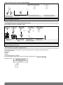
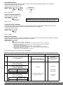
8.3 Connecting the relay outputs
If activated, the “Tamper” input (for connecting potential-free conductors only) protects one of the 2 wired outputs (see
“Summary of parameters, parameter 48” in control panel manual).
Use a 0.22 mm2 twisted wire with a maximum length of 200 m for the connection.
Relay outputs 1 and 2 are activated in relation to the chosen parameters (see “Summary of parameters, parameters 46 and
47”).
Electrical characteristics of relay outputs:
• relay outputs 1 and 2 have 3 terminals:
- 1 break: R
- 1 common: C
- 1 make: T
• 0.5 A 24 V AC or 1 A 30 V DC
Electrical characteristics of the connection terminal block
IMPORTANT: connect the outputs with the power off.
!
Hardwired
detector input
J6
Tamper
input
J5
J2
T
C Control panel
relay 2 output
R
J1
T
C Control panel
relay 1 output
R
Do not connect the 230 V mains supply to the relay outputs.
Example 1: connection of relay 1 and 2
outputs to a recording controller
Power supply
12 V back-up
Recording controller
Channel 1
OPERATING/NOT
J2
J1
Channel 2
ALARM
(active with no alarm,
INACTIVE WITH ALARM)
Example 2: connection of relay 2 output
to NO alarm input of video recorder
Video recorder
NO
alarm
input
J2
J1
30
INSTALLATION
MODE
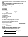
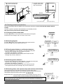
8.4 Fixing the control panel in place
1. Remove the tamper washer located on the
back of the base.
2. • To be able to install the control panel, there must be a clearance
of 5 cm to the left and 3 cm on top of the base to allow for the
hinge and a clearance of 18 cm below the base to open or lock
the control panel.
2. • Fix the base at the 3 points using suitable plugs and screws.
Detachable
tamper washer
Fixing holes without washer
3 cm
Pozidriv 22
Pozidriv
Detachable tamper
washer
5 cm
wall
Tamper hole with washer (A)
18 cm
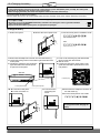
3. Position the control panel open at 45 ° (A)
in relation to the base and place the base
hinge pins inside the hinges.
A
4. Thread each cable through the cable trough in the base and
remove the pre-cut parts for cable insertion at the bottom of the
base.
5. Position the cable clamp and tighten the cables enough so that
they do not move when pulled (the cable clamp and screws are in
the bag of accessories provided).
For insertion of
lithium power
45°
Tamper pin
Cable clamp
• Make sure there are no wires blocking the power pack
compartment in the base and that the cover can be closed.
• Tighten the cables enough so that they do not move when pulled.
A 45°
31
6. A. Close the control panel.
B. Put the cover back on.
7. Lock the control panel
using the screw in the
bag of accessories.
B
A
Side view
Control panel locking
Control panel opening
8.5 Checking products and radio links
To ensure long-lasting radio link reliability, once the products have been installed, each radio link must be checked
carefully.
To do this, repeat the operations described below for all installed products.
This check must be performed in installation mode.
8.5.1 Checking remote control units
“bip, off, remote
control unit X”
Press the “Off” button on the remote control units and the control panel
will issue the voice message: “bip, off, remote control unit X”.
))
8.5.2 Checking keypads
)))
“bip, off, remote
control unit X”
Press the “Off” button on the keypads and the control panel will issue
the voice message: “bip, off, remote control unit X”.
))
“beeep”
)))
8.5.3 Checking door/window or multicontact detectors
• Press the “test” button on the detectors (> 5 s) and the control panel
issues the voice message: “bip, test, detector X, group Y,
(immediate, time-delayed or combined)”.
• Open the protected exits and the control panel will issue the voice
message: “bip, intrusion, detector X”.
“bip, test, detector X,
group Y, (immediate, timedelayed or combined)”
))
)))
“bip, test, detector X,
group Y, (immediate, timedelayed or combined)”
8.5.4 Checking motion detectors
• Press the “test” buttonon the motion detectors (> 5 s) and the control panel
issues the voice message: “bip, test, detector X, group Y,
(immediate, time-delayed or combined)”.
• Move around in the area protected by the motion detectors and the
control panel issues the voice message: “bip, intrusion, detector X”.
))
)))
8.5.5 Checking sirens, radio repeater relays and receivers automatically
This test checks the two-way radio link between the control panel, sirens, r
adio repeater relays and receivers. The control panel queries and activates the sirens,
radio repeater relays and receivers 3 times. Enter:
“bip, test, siren X”
(
(
32
or
(
((((
IMPORTANT: if the sirens, radio repeater relays or receivers have a power supply fault (lithium
power pack flat), the siren, radio repeater relay and receiver indications are followed by an
audible signal specifying this fault.
((((
(
((((
((((
Example with siren: • the control panel issues the voice message: “bip, test, siren X”,
• the siren issues a continuous beep and its strobe flashes for 3 s.
9. Performing a real test
USER MODE
First put the system in user mode.
IMPORTANT
• The sounding level of the siren can cause hearing disorders and the necessary precautions must therefore be taken when
testing triggering.
• Let correspondents know beforehand.
1. Close the exits and leave the protected areas
for a period of 90 s.
2. Arm the system
ƒ
• on receipt of the command, the control panel
responds: “bip, Armed”
3. Wait until the end of the exit time delay
ƒ
“bip, Armed”
“Armed”
• the control panel issues the voice message:
“Armed”
4. Enter a protected room
((((
(
(
(
((((
(
(( ( (
• the control panel and siren are triggered,
• the telephone dialler calls the programmed
correspondents according to the type
of event transmitted (1)
((((
ƒ
5. Let the sirens sound for 30 s then stop
the system
ƒ
• on receipt of the “Off” command, the sirens stop
and the control panel issues the following type
of voice message:
“bip, Off, on 21/04/2012 at 7:30 PM,
intrusion, detector 3, group 1”
6. Check the alarm has been transmitted by telephone
to the programmed correspondents (1) (2).
(1) If transmission module installed.
(2) Disarming the system stops transmission of the call to correspondents (for calls to individuals only).
33
10. Maintenance
10.1 Fault indications
The control panel supervises and identifies products in the installation. It monitors the state of:
• the power supply,
• the radio links,
• the tamper contact,
• the availability of the telephone line (1),
• the exits.
If a fault has been memorised, the control panel issues a voice message to indicate the fault after one of the following
system commands:
• arm,
• disarm,
• system status query.
The voice message indicates:
• the system status,
• the type of fault:
- power,
- radio,
- tamper,
- network (telephone line) (1)
- exit (open or inhibited),
• the identity of the product with a fault.
Example following an Arm command:
“bip, armed partial one,
bip, fault, tamper, control panel,
bip, fault, radio, detector 3,
bip, fault, voltage, siren 1,
bip, exit 4 opened”
IMPORTANT
Each product provides local indication of its own power fault by:
• its LED failing to light up (keypad and detector),
• an audible signal (siren).
In spite of its power fault, the product continues to operate normally for several days.
10.2 Vocal alarm indications
Any alarms occurring since the last time the system was armed are indicated vocally by the control panel when the system is
disarmed. The next time the system is armed, the alarms are deleted from the memory.
The vocal alarm memory can contain up to 10 alarms. These are indicated from the most recent to the oldest.
Vocal indications specify:
• the date and time the alarm occurred,
• the type of alarm,
• the identity of the product having triggered the alarm.
Example following a disarm command:
“bip, Off,
bip, on 28/01/2012 at 5:57 PM,
intrusion, group 1, detector 3,
bip, on 28/01/2012 at 4:12 PM,
tamper, siren 1”
(1) If transmission module installed.
34
10.3 Consulting the events log
The events log contains the last 1,000 time and date-stamped events occurring in the system. It also keeps track of specific
system operation and maintenance events.
The events log can be consulted:
• locally, using the control panel keypad,
• locally using the configuration tool,
• remotely using the data loading software (1).
The events log records:
• intrusion protection status changes,
• system remote commands (1),
• automatic inhibitions of exits remaining open,
• activation of each detector belonging to an armed group,
• alarms,
• fault occurrence and clearance,
• telephone transmissions (1),
• identification of intervention by remote access code (1),
• access for system configuration modifications,
• deactivation or reactivation of detectors (via data loading).
To access the events log locally using the control panel keypad:
1. Remove the cover.
2. Enter:
master code
installer code
then press,
for next
ƒ
ƒ
ƒ
ƒ
for repeat
for previous
for fast forward (10 events at a time)
to end
Each event in the log is recorded with the following information:
• date and time,
• name of event,
• detection zone for intrusion alarms,
• identity of devices triggering the event.
Example:
“bip, on 25/02/2012 at 3 PM,
intrusion, group 1, detector 3”
“bip, on 13/01/2012 at 12 PM,
tamper, siren 1”
(1) If transmission module installed.
35
INSTALLATION
MODE
10.4 Changing the battery
IMPORTANT
• If the activated product (except for the remote control unit) has a power fault (lithium power pack flat), the control panel
indications are followed by the message “fault, power supply”.
• Before changing the battery, disconnect the telephone connector from the wall socket (1).
The control panel monitors its own battery.
When a power fault occurs, the control panel issues the voice message “fault, power supply” following a command.
• The lithium battery pack must be replaced with the same type of pack with the same technical characteristics,
i.e. 2 x (3.6 V - 13 Ah).
• We advise you to use the DAITEM BatLi22 battery available in the catalogue in order to guarantee individual
safety and equipment reliability.
• Dispose of the waste lithium power pack in an appropriate recycling bin.
Li
To change the battery:
1. Disarm the system:
2. Remove the control panel cover.
3. Put the control panel in installation mode
master code (Factory: 0000)
then,
installer code (Factory: 1111)
4. Disconnect the telephone connector from the wall socket (1).
5. Loosen the locking screw on the bottom right-hand side of the
control panel.
6. Introduce a screwdriver into the bottom
right-hand side of the base and push
to open the control panel.
7. Press on the unlocking key and slide the flat
lithium power pack downwards.
8. Wait for 2 min,
9. Position the new lithium power pack on the
guide rails and slide it upwards until it locks
into position.
Side view
Unlocking key
Control panel locking
Control panel opening
11. Lock the control
panel using the
screw.
10. A. Close the control panel.
B. Put the cover back on.
12. Reconnect the telephone connector to
the wall socket (1).
13. Put the control panel in user mode:
A
IMPORTANT: the date and time must
be reprogrammed after changing the
battery.
B
(1) If transmission module installed.
36
11. Appendix
Accessories and power supplies to be used for control panel-diallers
1. Transmission module SH501AX: PSTN + Ethernet (ADSL)
Media used
Power supplies and accessories to be used
References
PSTN only
PSTN +
Ethernet (ADSL)
Ethernet (ADSL)
only
Power supplies from the catalogue to be used
200-240 VAC 50-60 Hz / 4.5 VDC 2.2 A
Internal mains power module
RXU01X
BatLi22 2 x (3.6 V, 13 Ah) Lithium power pack
BatLi 22
Li-Ion: 3.7 V/1.2 V Li-Ion rechargeable back-up battery
order
order
not used
not used
RXU03X
Choice between:
• BatLi 22 (supplied)
or
• mains power
module (order)
+ Li-Ion (order)
order
order
RJ45/RJ45 Ethernet network cable
830-99X
/
order
order
PSTN cable: RJLL/T
851-99X
order
order
/
PSTN cable: RJ11/(RJ45-RJ-45)
856-99X
order
order
/
ADSL master filter (partial unbundling)
900-99X
/
order
order
see catalogue
/
order
order
Accessories from the catalogue to be used
IP cameras and/or image transmission detectors
Accessories to be used that are not available in the catalogue
Mains connection cable for 200-240 VAC 50-60 Hz /
4.5 VDC 2.2 A internal mains power module
/
/
order
order
Cable clamp for mains connection cables
/
/
order
order
IP camera video connection cables
/
/
order
order
Bag of accessories: cable clamps + screws
/
supplied
supplied
supplied
2. Transmission module SH502AX: GSM/GPRS + Ethernet (ADSL)
Media used
Power supplies and accessories to be used
References
GSM/GPRS
only
GSM/GPRS +
Ethernet (ADSL)
Ethernet (ADSL)
only
Power supplies from the catalogue to be used
Choice between:
• BatLi 22 (supplied)
+ compulsory
Li-Ion (supplied)
or
• mains power
module (order)
+ Li-Ion (supplied)
for GSM incoming
calls
order
order
not used
not used
supplied
supplied
830-99X
/
order
order
GSM remote antenna
RXA03X
order
order
/
ADSL master filter (partial unbundling)
900-99X
/
order
order
see catalogue
order
order
order
200-240 VAC 50-60 Hz / 4.5 VDC 2.2 A
Internal mains power module
RXU01X
BatLi22 2 x (3.6 V, 13 Ah)
Lithium power pack
BatLi 22
Li-Ion: 3.7 V/1.2 V Li-Ion rechargeable back-up battery
RXU03X
Accessories from the catalogue to be used
RJ45/RJ45 Ethernet network cable
IP cameras and/or image transmission detectors
Accessories to be used that are not available in the catalogue
Mains connection cable for 200-240 VAC 50-60 Hz /
4.5 VDC 2.2 A internal mains power module
/
order according
to power supply
order
order
Cable clamp for mains connection cables
/
order according
to power supply
order
order
IP camera video connection cables
/
order
order
order
SIM card
/
order
order
order
Bag of accessories: cable clamps + screws
/
supplied
supplied
supplied
37
3. Transmission module SH503AX: PSTN + GSM/GPRS + Ethernet (ADSL)
Media used
Power supplies
and accessories
to be used
(PSTN+
GSM/GPRS)
only
Ref.
PSTN
+ GSM/
GPRS
+ ADSL
(PSTN
+ ADSL)
only
(GSM/
GPRS
+ ADSL)
only
PSTN
only
GSM/GPRS
only
ADSL
only
Choice
between:
• BatLi 22
(supplied)
or
• mains power
module (order)
+ Li-Ion
(supplied)
Choice
between:
• BatLi 22
(supplied)
+ compulsory
Li-Ion
(supplied)
or
• mains power
module (order)
+ Li-Ion
(supplied) for
GSM incoming
calls
not used
Power supplies from the catalogue to be used
200-240 VAC 50-60 Hz /
4.5 VDC 2.2 A
Internal mains power module
BatLi22 2 x (3.6 V, 13 Ah)
Lithium power pack
Li-Ion: 3.7 V/1.2 V
Li-Ion rechargeable
back-up battery
Choice
between:
RXU01X • BatLi 22
(supplied)
+ compulsory
Li-Ion
(supplied)
BatLi 22
or
• mains power
module (order)
+ Li-Ion
(supplied) for
RXU03X
GSM incoming
calls
order
order
order
not used
not used
not used
supplied
supplied
supplied
order
supplied
Accessories from the catalogue to be used
RJ45/RJ45
Ethernet network cable
830-99X
/
order
order
order
/
/
order
GSM remote antenna
RXA03X
order
order
/
order
/
order
/
PSTN cable: RJLL/T
851-99X
order
order
order
/
order
/
/
PSTN cable: RJ11/(RJ45-RJ-45) 856-99X
order
order
order
/
order
/
/
ADSL master filter
(partial unbundling)
900-99X
/
order
order
order
/
/
order
IP cameras and/or image
transmission detectors
see
catalogue
order
order
order
order
/
order
order
Accessories to be used that are not available in the catalogue
Mains connection cable
for 200-240 VAC 50-60 Hz /
4.5 VDC 2.2 A
internal mains power module
/
order according
to power supply
order
order
order
order according order according
to power supply to power supply
order
Cable clamp for mains
connection cables
/
order according
to power supply
order
order
order
order according order according
to power supply to power supply
order
IP camera video connection
cables
/
order
order
order
order
/
order
order
SIM card
/
order
order
/
order
/
order
/
Bag of accessories:
cable clamp + screws
/
supplied
supplied
supplied
supplied
supplied
supplied
supplied
4. Transmission module SH504AX: Ethernet (ADSL)
Power supplies and accessories to be used
References
Ethernet (ADSL) media
200-240 VAC 50-60 Hz / 4.5 VDC 2.2 A internal mains power module
RXU01X
supplied
BatLi22 2 x (3.6 V, 13 Ah) lithium power pack
RXU03X
supplied
RJ45/RJ45 Ethernet network cable
830-99X
supplied
ADSL master filter (partial unbundling)
900-99X
order
see catalogue
order
Mains connection cable for 200-240 VAC 50-60 Hz / 4.5 VDC 2.2 A
internal mains power module
/
order
Cable clamp for mains connection cables
/
order
IP camera video connection cables
/
order
Bag of accessories: cable clamp + screws
/
supplied
Accessoires présents au catalogue
Accessoires à prévoir présents au catalogue
IP cameras and/or image transmission detectors
Accessoires non présents au catalogue
38
12. Summary of parameters
Access code parameters
Parameter description
Essential parameter-setting
Factory
parameters
Parameter-setting sequence
Possible values
Page
Master code
MMMM * 50 * ? ? ? ? * ? ? ? ? **
0000
code with 4, 5 or 6 digits
17
Installer code
I I I I * 51 * ? ? ? ? * ? ? ? ? **
1111
code with 4, 5 or 6 digits
17
Remote monitoring
RRRR * 52 * ? ? ? ? * ? ? ? ? **
2222
code with 4, 5 or 6 digits
18
User codes
MMMM * 2 X X * UUUU * UUUU **
-
X: 1 to 32
22
Access restricted
to specific command
button/s
MMMM * 2 X X * UUUU * UUUU * T **
-
T: personalised command button/s
22
Access restricted
to specific groups
MMMM * 2 X X * UUUU * UUUU * T **
-
T: buttons of groups 1 to 8
(according to type of control
23
User code
enabled/disabled
MMMM * 2 X X * Y **
user code
non programmé
X: 1 to 32
Y: 0 = disabled
1 = enabled
23
Number of access code
digits
* 69 * ? **
4 chiffres
code with 4, 5
or 6 digits (usage extérieur)
17
MMMM = master code
I I I I = installer code
RRRR = remote monitoring
Consulting parameters
Return to factory default settings
...
...
parameter n°
parameter n°
installer code
INSTALLATION
MODE
USER MODE
2 flashes
every 10 s
ins
tal
ler
ins
tal
ler
UUUU = user code
co
de
co
de
de
co
ter
s
ma
e
od
rc
e
t
s
ma
TEST MODE
Factory:
installer code: 1111
master code: 0000
1 flash every 5 s
IMPORTANT: for security reasons, the keypad automatically switches back to user mode after 4 hours without a command
being issued.
Consulting the events log
then press,
for next
ƒ
ƒ
ƒ
ƒ
for repeat
for previous
for fast forward (10 events at a time)
to end
39
Control panel parameters
Parameter
description
Essential parameter-setting
Parameter-setting
sequence
Factory
parameters
Exit time delay
Entrance time delay
Delayed sounding
Duration of sounding
upon intrusion
End of exit time delay
when last exit is closed
Audible indication level
Type of command
audible indications
Activation of audible call
and chime
Acknowledgement
of tamper alarms
in installation mode
Validation of message
content on 1 or 2 bands
Deletion of built-in siren
* 1 * ? ? **
* 2 * ? ? **
* 3 * ? ? **
* 4 * ? ? ? **
90 s
20 s
0s
90 s
* 7 * D * G **
-
Choice of speech
synthesis language
* 17 * ? **
Manager reset
* 18 * ? **
Triggering of built-in
siren upon intrusion
Protection active
indication
Siren triggering in
Armed presence mode
* 20 * ? **
Media fault indications
* 26 * ? ? **
Radio tamper
* 27 * ? ? **
Radio fault indication
* 28 * ? ? **
Entry route
* 30 * ? **
Exit route
* 31 * ? **
Blue light indication
* 34 * ? **
* 11 * ? **
* 12 * ? **
* 13 * ? **
* 14 * ? **
* 15 * ? **
* 16 * ? **
* 21 * ? **
* 22 * ? **
Allocation of sounding
* 37 * ? ? ? ? **
to one or several groups
* Depending on type of control panel
Possible values
0 to 90 s
0 to 90 s
0 to 60 s
20 to 180 s
D: detector n°
G: group n° from 1 to 8
average (=4)
1 to 8
vocal
0: disabled
1: vocal
enabled
0: disabled
1: vocal
enabled
0: disabled, no triggering
1: enabled, triggering of telephone
transmission**
validation
0: validation on 1 radio band
on 1 radio band
1: validation on 2 radio bands
siren enabled
0: siren enabled
1: siren disabled
English
0: French
1: Italian
2: German
3: Spanish
4: Dutch
5: English
disabled
0: disabled
1: enabled
enabled
0: disabled
1: enabled
enabled
0: disabled
1: enabled
enabled and vocal 0: disabled
1: enabled and vocal
2: enabled (loud 15 s)
events log alarm
0: events log alarm memorisation
memorisation +
1: events log alarm memorisation + vocal
vocal memorisation
indication + fault message transmission
if back-up media present**
2: events log alarm memorisation + vocal
indication + fault message transmission
if back-up media present + start of alarm
confirmation duration +
- if system is totally armed
and PSTN is cut off > 1 min
fi 15 s triggering
- if system is totally armed and PSTN
is cut off > 15 min or GSM is cut off
fi 90 s triggering**
3: events log alarm memorisation + vocal
indication + fault message transmission
if back-up media present +
- if PSTN cut off > 1 min fi 15 s triggering
- if PSTN cut off > 15 min or GSM cut off
fi 90 s triggering**
enabled 24/24
0: disabled
transmission**
1: enabled 24/24 (transmission** + indication
+ indication
+ events log alarm memorisation
+ events log alarm
+ alarm triggering)
memorisation
2: enabled 24/24 (transmission ** + indication
+ events log alarm memorisation)
indication
0: indication disabled
and telephone
1: indication and telephone transmission**
transmission
2: local indications
enabled
0: disabled
1: enabled
disabled
0: disabled
1: enabled
enabled
0: enabled
1: disabled
all groups
choice of group(s): 1 to 8*
** If transmission module installed
40
Page
19
20
24
20
22
11
26
27
11
24
24
26
26
27
27
20
20
28
20
Control panel parameters (cont.)
Parameter
description
Groups enabled
in Armed Partial One
Groups enabled
in Armed Partial Two
Groups enabled in
Armed Presence mode
Programming
of common group
Arming blocked
Parameter-setting
sequence
Possible values
Page
* 41 * ? ? ? ? **
group 1
choice of group(s): 1 to 8*
25
* 42 * ? ? ? ? **
group 2
choice of group(s): 1 to 8*
25
* 43 * ? ? ? ? **
group 1
choice of group(s): 1 to 8*
25
* 44 * C * A **
disabled
C: common group n° (from 1 to 8)*
A: choice of association group(s) (from 1 to 8)*
blocked
blocking condition
if supervision
0: blocking disabled
command not
1: blocking if faults
received (20 min) 2: blocking if self-monitoring (mechanical
and exits checked
tamper fault and fault on transmission
at the end of exit
media or exit(s) open)
time delay
3: blocking if supervision not received (20 min)
4: blocking if supervision not received (20 min)
and exits checked at end of exit time delay
type of relay
type of activation:
triggering: bistable A = event appearance
D = event disappearance
A and D =
0: manual (keypad or radio command)
0: manual
1: single intrusion
2: confirmed intrusion
3: confirmed intrusion (+ tamper
and alert command)
4: deterrence
5: prealarm
6: fire
7: technical
8: system disarmed
9: system armed
10: PSTN network cut
11: GSM network cut
12: ADSL network cut
13: main dialler unavailable
14: all
T = relay activation duration:
Impulse: 0.5 s
Timer: from 1 s to 180 s
disabled
0: disabled
1: enabled
disabled
T = input type:
0: disabled
1: exit
2: intrusion
3: deterrence
4: prealarm
5: fire
6: technical
8: alert
9: silent alarm
10: chime
25
* 45 * ? **
Relay 1 output activation depending on the type
of relay triggering
• bistable:
* 46* 0 * A * D **
• impulse:
* 46 * 1 * A
• timer:
* 46 * 2 * A * T **
Relay 2 output activation depending on the type
of relay triggering
• bistable:
* 47* 0 * A * D **
• impulse:
* 47 * 1 * A
• timer:
* 47 * 2 * A * T **
Relay tamper loop
activation
Hardwired input
programming
Factory
parameters
* 48 * ? **
* 57 * T **
* Depending on type of control panel
** If transmission module installed
41
19
28
28
27
Control panel parameters (cont.)
Parameter
description
Command button
personalisation
Parameter-setting
sequence
Factory
parameters
Possible values
Page
T: button to be personalised
C: command n° (see table of personalised
commands)
AT: access type
0: direct access
1: access via code
D: detector n°
G: group n° from 1 to 8
T: time delay = 0: immediate
1: time-delayed
2: combined
0: inhibitable
1: uninhibitable
0: disabled
1: enabled
T: product type
0: hardwired input
2: detector
3: command
4: siren
5: dialler**
7: radio repeater relay or receiver
P: product n° from 0 to 80
from 01 to 31
from 01 to 12
from 00 to 99
from 00 to 24
from 00 to 59
0: disabled
1: audible
0: disabled
1: audible
0: disabled
1: audible
G: group n° from 1 to 8*
max duration 3 s
T: product type:
2: detector
3: remote control unit
4: siren
5: dialler **
7: radio repeater relay or receiver
n°: product n°
23
* 58 * T * C * AT **
configuration 1
Allocation of a
programmed detector
* 60 * D * G * T **
acces
to commands
via code
group 1
Uninhibitable detector
* 61 * detector n° * ? **
inhibitable
Chime
* 62 * detector n° * ? **
disabled
Vocal personalisation
of products
* 66 * T * P # “message” #
“message repeated” *
no pre-recorded
message
Date
* 70 * DD * MM * YY **
Time
* 71 * HH * MM **
Type of warning
indication
Type of deterrence
indication
Type of prealarm
indication
Vocal personalisation
of groups
Product inhibition
Product reactivation
Deletion of a
programmed product
* 72 * ? **
DD: 01
MM: 01
YY: 12
HH: 00
MM: 00
audible
* 73 * ? **
audible
* 74 * ? **
audible
* 131 * G # “message” #
“message repeated” *
* 190 * T * product n° **
* 191 * T * product n° **
* 194 * T * product n° **
no pre-recorded
message
-
* 195 ***
-
-
15
* 196 ***
-
15
Deletion of parameters
Overall deletion
* 197 ***
* 198 ***
-
Automatic Arm/Disarm
function
* 511 * ? **
disabled
installer code: 1111
master code: 0000
remote monitoring code: 2222
return to factory parameters
overall deletion of recognition programming
and return to factory parameters
0: disabled
1: enabled
Overall deletion
of programming
Deletion of access
codes
* Depending on type of control panel
** If transmission module installed
42
24
26
28
21
18
18
25
25
25
21
29
29
15
29
29
28
Summary of commands
Command description
Parameter-setting sequence
Page
Operating mode check
# 4 ##
16
Radio link check
# 5 ##
32
Programmed product programming check
# 11 ##
14
Commands for personalisation
IMPORTANT
• In installation mode, the keypad commands
can be accessed directly.
• All Disarm or Arm commands as well as the
System status command are accessed via a code.
Enter:
...
button to be
personalised
Command description
command
n°
Command n°
access type:
• 0: direct access
• 1: access via code
Command description
Command n°
Command description
Command n°
Disarm (1)
21
Off light
52
On relay 3
Alert
22
On light
54
Relay 3 toggle switch
86
Arm (1)
23
Light toggle switch
56
Relay 3 timer
88
Silent alarm
24
Light timer
58
Off relay 4
92
Partially arm 1 (1)
25
Off relay 1
62
On relay 4
94
Partially arm 2 (1)
27
On relay 1
64
Relay 4 toggle switch
96
Fire alarm
32
Relay 1 toggle switch
66
Relay 4 timer
98
Arm presence
33
Relay 1 timer
68
Off relay control panel 1
112
Silent command
36
Off relay 2
72
On relay control panel 1
114
Stop indications (1) (2)
37
On relay 2
74
Off relay control panel 2
122
Chime
38
Relay 2 toggle switch
76
On relay control panel 2
124
Audible signal
42
Relay 2 timer
78
System status (1)
129
No command
44
Off relay 3
82
(1) Command with code access only.
(2) Used to stop indications concerning a technical alarm, an alert or a tamper alarm without changing the system status.
Important: telephone transmissions are not interrupted.
Personalising a command button to arm or disarm groups 1 to 8
IMPORTANT: all disarm or arm commands can only be accessed via a code.
• To personalise a button so that it arms groups 1 to 8, enter:
...
button to be
personalised
group(s) 1 to 8
• To personalise a button to disarm groups 1 to 8, enter:
...
button to be
personalised
group(s) 1 to 8
43
84
13. Technical data
Technical specifications
Power supply
Battery life
Average current consumed
Average humidity rate
Radio link
Control panel specifications
Operating temperature
Degrees of mechanical protection
Environment
Tamper protection
Supervision
Siren acoustic power
Audible alarm
Dimensions
Weight (without battery)
Security grade
Environmental class
Control panel SH320AU • SH340AU • SH380AU
• BatLi 22 lithium power pack: 2 x (3.6 V – 13 Ah)
• or 200-240 VAC 50-60 Hz / 4.5 VDC 2.2 A mains power module backed up by Li-Ion 3.7 V
1.2 Ah battery (not supplied)
5 years in normal conditions of use
335 µA
from 5% to 75% without condensation at 25°C
TwinBand®, 400/800 MHz
• SH320AU: 2 separate groups
• SH340AU: 4 separate groups
• SH380AU: 8 separate groups
progressive deterrence
personnel protection
15 remote control units maximum
• SH320AU: 20 intrusion detectors maximum
• SH340AU: 40 intrusion detectors maximum
• SH380AU: 80 intrusion detectors maximum
10 deterrence devices maximum
32 user codes
• 5 radio repeater relays maximum
• 3 diallers maximum (transmission module included)
vocal personalisation of detectors (40 max)
system saved to S.I.T.E. NVM stick (optional)
built-in command keypad
built-in remote control operation (if transmission module installed)
log of last 1,000 date and time-stamped events
2 hardwired outputs + 1 hardwired input (optional)
- 10 °C to + 55 °C
IP 31 / IK 04
indoors
degree of pollution: 2
category of overpressure: II
maximum altitude: 2 000 meters
against opening
against removal
against line cuts (if transmission module installed)
against attempts to discover radio codes
against radio interference
radio
lithium power pack BatLi22 / 230 VAC mains power module / battery Li-Ion
tamper
108 dB(A) at 1 m
built-in
232 x 232 x 67,7 mm
1 200 g
grade II according to EN 50131-3
class II according to EN 50130-5
Description of symbols
The product is in conformity with the fundamental obligations as regards safety, of hygiene and environmental protection.
Risk of electric
shock
Risk of electric shock.
Li
In order to avoid harming the environment and human health, you should not dispose of this product with normal household
waste, do not not place in a waste bin with household waste. It must be given to a point of collection suitable for the
categorisation, treatment, and recycling. The lithium power supplies contain substances which can pollute the environment.
They must be given to an approved recycling centre.
The power supply MUST be labelled with this symbol of double insulation, for a 230 VAC supply without ground connection.
For indoor use only.
!
The note must absolutely be consulted before installation, use and maintenance of the equipment.
44
14. Installation sheet (pull-out)
Customer name: ______________________________________________________________ Date installed:
List of detectors
Detector
n°
Personalised
message
Group
Time delay
Alarm
level
Location
e.g. motion detector
N° 1
control panel
protection detector
1
Time-delayed
deterrence
dining room
"
Intrusion detector
45
List of keypads and keyfobs
Keypad/keyfob type
Keypad/keyfob n°
Siren
Distribution
List of sirens
List of radio repeater relays
Radio repeater relay
Distribution
46
47
To obtain advice when installing your system or before
returning equipment, please contact the Daitem technical
support team (44 (0) 844 824 6693) or check the web site at:
www.daitem.co.uk
A team of qualified technicians will advise you what to do.
DECLARATION OF CONFORMITY
13
Manufacturer: Hager Security SAS
Address: F-38926 Crolles Cedex - France
Product type: Control panel
Trade mark: Daitem
We declare under our sole responsibility that the product to which this declaration relates is
compliant with the essential requirements of the following directives:
• R&TTE Directive: 99/5/EEC
• Low voltage directive: 2006/95/EC
• Directive ROHS: 2002/95/EC
in compliance with the following harmonised European standards:
SH320AU SH340AU SH380AU
Products code
EN 300 220-2 V3.3.1
X
X
X
EN 50130-4 (95) + A1 (98) + A2 (2002)
X
X
X
EN 55022 & 55024 (2002)
X
X
X
EN 60950 (2006)
X
X
X
EN 301 489-1 V1.8.1
X
X
X
This product can be used in all EU, EEA Countries and Switzerland.
Crolles, 02.01.2013
Signature:
Patrick Bernard
Director of Research and Development
805134/B - 05.2013
Non-binding document, subject to modification without notice.