1
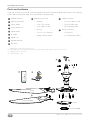
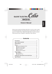
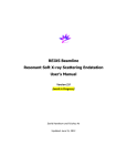
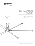
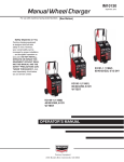
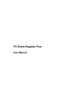
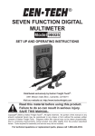
Installation Guide
A2
Installation Guide:
Jan. 2014
Rev. N
Model Number:
K3150-A2
S3150-A2
May be protected by one or more of the following patents: www.bigasssolutions.com/patents
Haiku and the Haiku logo are trademarks of Delta T Corporation, registered in the United States and/or other
countries. The information contained in this document is subject to change without notice.
Thank you for buying the world’s most innovative fan. Please take a few moments to register your
fan with us online at www.haikufan.com/warrantyregistration.
This product is sold by a plant whose
Management System is certified as
being in conformity with ISO 9001:2008.
4004784
4004783
Conforms to ANSI/UL STD 507–Electric Fans
Certified to CAN/CSA C22.2 No. 113–Fans & Ventilators
This device complies with Part 15 of
the FCC Rules. This device complies
with Canada ICES-003, Class B.
Contents
INTRODUCTION
1
2
Installing the anchor bolts
Technical specifications
Securing the hanger plate
Parts & hardware
Unpacking your fan
3 Determining fan location
Tools needed
Preparing the mounting location
FAN ASSEMBLY
5 Installing the airfoils
6
9 Installing the safety anchor hook
Hanging the fan
Fan diagram
PREPARATION
4
OPTIONAL HANGER PLATE
About Haiku
Securing the safety cable
ELECTRICAL
10
11
12
13
Installing the lower cover
Installing the wiring cover & trim
Wiring the fan
Installing the wiring cover
Wire color chart
Wiring diagram (without EMI filter)
Wire color chart
Wiring diagram (with EMI filter)
Wire color chart
Wiring diagram (with terminal strip)
OPERATION
Powering the fan
FAN MOUNTING
(OUTLET BOX)
Attaching the mounting bracket
7 Hanging the fan
Securing the safety cable
Replacing remote control battery
14
Changing fan speed
Sleep mode
Timer mode
Whoosh mode
Operating the light
15 Reversing fan rotation
FAN MOUNTING
(CONCRETE CEILING)
Preparing the ceiling hook
8 Hanging the fan
Fan mode indicators
TROUBLESHOOTING
16 General troubleshooting
Securing the safety cable
MAINTENANCE
17 Annual maintenance
HAIKU® by Big Ass Fans
i
IMP O RTA N T S AF ETY I N ST RU CT IO N S
Read and save these instructions prior to installing and operating your Haiku. Retain
this installation guide for maintenance and troubleshooting information. If you have
further questions, contact Haiku Customer Service at www.haikufan.com/service.
WARNING: To reduce the risk of fire, electric shock, and serious bodily injury to persons, observe the
following:
• Installation work and electrical wiring must be done by qualified person(s) in accordance with all applicable
codes and standards.
• When cutting or drilling into ceiling, do not damage electrical wiring and other hidden utilities.
• Use this fan only in the manner intended by the manufacturer.
CAUTION: The installation of this fan must be in accordance with the requirements specified in this
installation manual and with all national and local electrical codes. Code compliance is ultimately YOUR
responsibility!
WARNING: If installing the fan in Australia, a licensed electrician must perform the electrical installation.
CAUTION: Exercise caution and common sense when powering the fan. Do not connect the fan to a
damaged power source. Do not attempt to resolve electrical malfunctions or failures on your own.
WARNING: The fan must be used with the supplied remote control. Other parts cannot be substituted.
CAUTION: When service or replacement of a component in the fan requires the removal or disconnection of
a safety device, the safety device must be reinstalled or remounted as previously installed.
WARNING: Power must be disconnected before installation and servicing, cleaning, and other usermaintenance. Failure to disconnect power creates risk of fire, electric shock, and serious bodily injury.
CAUTION: The product warranty will not cover equipment damage or failure that is caused by improper
installation or operation.
WARNING: To reduce the risk of fire, electric shock, or serious bodily injury when mounting the fan to an
outlet box, mount the fan to an outlet box that is suitable for fan support, and use the mounting screws
provided with the outlet box. Outlet boxes used for luminaires are usually not acceptable for fan support and
may need to be replaced. If in doubt, consult a qualified electrician.
CAUTION: The fan must be mounted a minimum of 7 ft (2.1 m) from the floor and 3 ft (1 m) from the nearest
wall. If installing the fan in southeast Asia, the fan must be mounted a minimum of 2.4 m from the floor. The
ceiling should be stable with no shaking, high vibrations, or heavy impacts.
WARNING: Do not install the fan in an environment that is excessively dusty, conductive, corrosive, or gasfilled, is exposed to open flames, e.g., gas-burning stoves, is near strong chemicals or solvents, or where
there is excessive heat, shock, or vibration.
WARNING: Do not bend the airfoils when installing or servicing the fan. Do not insert foreign objects in
between the rotating fan airfoils.
CAUTION: This fan is not intended for use by persons (including children) with reduced physical, sensory,
or mental capabilities, or lack of experience and knowledge, unless they have been given supervision
or instruction concerning the use of the fan by a person responsible for their safety. Children should be
supervised to ensure that they do not play with the fan.
WARNING: Before installing or servicing the fan, ensure power is disconnected.
CAUTION: Haiku (K3150-A2) is rated for use in damp environments and can be operated indoors or
outdoors. Haiku Bamboo (S3150-A2) is not rated for damp environments and must be operated indoors only.
CAUTION: The fan will begin rotating when power is applied.
CAUTION: Do not use the fan with a dimmer switch.
ii
©2013 DELTA T CORP. ALL RIGHTS RESERVED.
I N TR ODUC TI O N
Thank you for your Haiku purchase and congratulations on your selection of an elegant, efficient, and
cost-effective way to stay cool! We are proud to assure you that the fan you have chosen is backed by
extensive research, thorough testing, and quality manufacturing.
If you have any questions or comments, please contact Customer Service by visiting our Web site at
www.haikufan.com/service.
About Haiku®
Haiku products are inspired by the seamless integration of natural forms and materials with the latest
technologies. Haiku fans consume up to 80% less energy than traditional ceiling fans and maximize
the sustainable use of global resources so you can now help save the planet in STYLE. Backed by the
engineering resources of Big Ass Fans, the fan of choice for smaller spaces that need extraordinary
air movement is crystal clear—it’s Haiku.
Technical specifications
Before assembling and installing your fan, review the technical specifications in the table below. A fan
diagram and parts list can be found on the following page.
Model
Model number
Fan diameter
Number of airfoils
Weight
Number of fan speeds
Operating voltage
Operating frequency
Full load amps
Wattage
Ambient operational temperature range
Operational humidity range
Status indication
HAIKU® by Big Ass Fans
Haiku® / Haiku® Bamboo
K3150-A2 / S3150-A2
60 in. (1.5 m)
3
13.2 lb (6 kg)
7
100–240VAC 1Φ
50–60 Hz
0.363A
Max: 60 Watts
Min: 4 Watts
32°–104° F (0–40° C)
20–90% non-condensing
LED display
1
INTRODUCTION (CONT.)
Parts and hardware
If you are missing any parts or hardware required for the installation or operation of your Haiku, contact
Haiku Technical Service. Note: Drawings below are not to scale.
1
10
Rubber bushing
11
Mounting hardware
Airfoil hardware
2
Mounting bracket
•
3
Wiring cover
•
8 mm Flat washer
•
(6) M5 Airfoil screw
•
8 mm Lock washer
•
(6) Airfoil grommet4
•
M8 Nut
•
2 mm x 2 mm Split pin
•
(4) Wire nut
•
Safety cable shackle3
•
(2) Wiring cover screw
1
4
Wiring cover trim
5 Lower cover
6 (3) Airfoil
M8 Bolt
•
(6) 5 mm Lock washer
12
Wiring hardware
7 Motor hub
8 Remote control
9 EMI filter2
1.
2.
3.
4.
Needed for outlet box mounting only.
If the EMI filter is included with your fan (country dependent), please install it with your fan.
Safety cable is not shown.
Haiku Bamboo only.
1
2
10
8
9
12
7
3
4
Haiku
6
11
Haiku Bamboo
Haiku
5
Haiku Bamboo
2
©2013 DELTA T CORP. ALL RIGHTS RESERVED.
Pr e par at i o n
Before assembling and operating your fan, review the following tips and guidelines to ensure a safe
and easy installation, particularly the safety guidelines on page ii. If you are not completely comfortable
or have questions about any aspect of the installation process, consult a structural engineer or
electrical contractor or contact Haiku Technical Service before beginning installation.
Unpacking the fan
As you remove the fan from its packaging, make sure you are not missing any components required
for assembly and operation. Refer to the fan diagram and the Parts and Hardware section for a list of
components. If you are missing a part required for installation, contact Haiku Technical Service.
If you ordered multiple fans, be sure to keep the components of each fan together! Certain
fan components are not interchangeable.
Determining fan location
Consider the following guidelines as you decide where to install your Haiku:
• Do not mount the fan in an environment that is excessively dusty, conductive, corrosive, or gas-filled,
near strong chemicals or solvents, or where there is excessive heat, shock, or vibration.
• Do not install the fan near open flames such as those from a gas stove.
• The ceiling should be stable with no high vibrations, shaking, or heavy impacts.
• Install the fan so that the airfoils are at least 7 ft (2.1 m) above the floor. If installing the fan in
southeast Asia, ensure that the airfoils are at least 2.4 m above the floor.
• Make sure the space around the fan has a clearance of at least 3 ft (1 m) from obstructions such as
cabinets, doors, or lighting fixtures.
• Make sure the space between the fan and ceiling is clear of any obstructions.
• Outlet box mounting: Install the fan where there is an outlet box or ceiling joist that is suitable for fan
support.
• Concrete ceiling mounting: Install the fan where there is a ceiling hook or other sufficient structural
support in the ceiling. If there is no ceiling hook at the fan site, the optional hanger plate can be
installed. The concrete mounting method is not available in North America.
HAIKU® by Big Ass Fans
3
PREPARATION (CONT.)
Tools needed
You will need the following tools to install the fan. If you are installing an outlet box, additional tools
may be necessary. Consult the outlet box manufacturer’s instructions.
• Ladder
• Hex key (provided)
• Wire stripper
• Adjustable wrench
• #1 Phillips screwdriver
Preparing the mounting location
For mounting methods not covered in this manual, contact Haiku Customer Service.
If you are mounting your fan to a ceiling-mounted outlet box, the outlet box must be suitable for fan
support. If there is not an outlet box at the location where you are installing your fan, one must be
installed on a ceiling joist or beam and properly wired. At least 8” (20 cm) of wiring should be hanging
from the outlet box. The illustration below shows a typical outlet box used for fan installations.
4
©2013 DELTA T CORP. ALL RIGHTS RESERVED.
F AN AS S EMB LY
Review the safety guidelines. If you are not completely comfortable or have questions about any
aspect of the installation process, consult a structural engineer or electrical contractor or contact Haiku
Technical Service for assistance.
Step 1. Installing the airfoils
Position the fan upside-down. Remove the protective covering from the bottom of the fan.
Moving clockwise around the fan, align each airfoil with a fan hub tab and firmly press it into place.
Make sure that the colored stickers match the colors of the stickers on the attachment of the fan hub. Loosely
secure the airfoils with the provided (6) airfoil screws and grommets. Once the airfoils are in position,
fully tighten the screws to secure the airfoils to the fan hub.
tip!
Visit www.haikufan.com to view installation videos illustrating the airfoil installation process.
Be careful not to damage the circuit board while installing airfoils!
Haiku® Bamboo
Haiku®
tip!
To ease airfoil installation, the (3) motor top screws can be loosened. Do not forget to retighten them!
Motor
top screw
HAIKU® by Big Ass Fans
5
FAN ASSEMBLY (CONT.)
Step 2. Installing the lower cover
If you purchased the wall control kit or LED light kit, proceed to the instructions included
with the kit. If installing both kits, install the wall control kit first. Return to these instructions
once the kits are installed.
Align the three tabs on the lower cover with the three slots in the undersides of the airfoils and secure.
Haiku® Bamboo
For Haiku Bamboo, simply snap the lower cover to the bottom of the fan hub.
Lower
Cover
Note: If installing the LED light kit, you will not
install the lower cover.
Haiku®
For Haiku, position the lower cover, and then place both hands flat on the cover and turn clockwise to lock
the lower cover into place.
Lower
Cover
Note: If installing the LED
light kit, you will not install
the lower cover.
Step 3. Installing the wiring cover and trim
With the fan in the upright position, remove the protective
covering from the extension tube.
Slide the wiring cover and wiring cover trim over the
extension tube, resting them on the fan hub.
If mounting the fan to a ceiling-mounted outlet box,
proceed to Fan Mounting (Outlet Box) on the following
page. If mounting the fan to a concrete ceiling, proceed
to Fan Mounting (Concrete Ceiling) on page 8.
6
Wiring
cover
Wiring
cover trim
©2013 DELTA T CORP. ALL RIGHTS RESERVED.
F A N MO UN TI N G ( OU T L E T B OX )
The ceiling-mounted outlet box must be suitable for fan support.
Step 4. Attaching the mounting bracket
Ensure wiring has been routed to the fan site.
Secure the mounting bracket to the outlet box with the hardware
supplied with the outlet box. Seat the rubber bushing in the eye
of the mounting bracket as shown.
Make sure to mount the bracket in the correct mounting
holes on the outlet box!
Step 5. Hanging the fan
Raise the fan to mounting bracket, and then attach it by
securing the extension tube bracket to the mounting
bracket with the mounting hardware as shown below.
Be careful not to drop any hardware in the wiring
cover during installation!
Safety
cable
Step 6. Securing the safety cable
Loop the safety cable around the mounting bracket,
and then secure it with the safety cable shackle.
Special Note: If you are installing the fan in Canada, the
safety cable must be secured to an existing part of the
building structure instead of the outlet box. Examples of
acceptable building structures include a wooden beam or a
metal mounting brace secured between two beams. In some
cases it may be necessary to install additional structural
material to provide attachment points. If you have concerns
about installing the safety cable, consult a structural engineer.
Proceed to Step 7. Wiring the fan on page 10.
HAIKU® by Big Ass Fans
7
FA N MO U N TIN G (CON CRETE CEILING)
The concrete mounting method is not available in North America.
Step 4. Preparing the ceiling hook
Seat the rubber bushing inside the eye of the ceiling fan
hook as shown. If there is not a ceiling hook at the fan site,
the hanger plate accessory should be installed. See the
following page for details on installing the hanger plate
accessory.
Make sure the hook is cast into the concrete
ceiling before seating the rubber bushing.
Step 5. Hanging the fan
Raise the fan to ceiling hook, and then attach it by securing
the extension tube bracket to the ceiling hook with the
mounting hardware as shown on the right.
Be careful not to drop any hardware in the wiring
cover during installation!
Step 6. Securing the safety cable
Loop the safety cable around the ceiling hook, and then secure
it with the safety cable shackle.
Proceed to Step 7. Wiring the fan on page 10.
Safety cable
& shackle
8
©2013 DELTA T CORP. ALL RIGHTS RESERVED.
O pt i o n al H an ge r P l at e
If mounting the fan to a concrete ceiling and a ceiling hook is not located at the fan site, a hanger
plate with a safety cable hook should be installed. The concrete mounting method is not available in
North America.
The safety cable must be installed with an anchor hook if mounting the fan with the hanger
plate accessory.
Step 1. Installing anchor bolts
Drill three 012 mm to 12.5 mm holes in the pattern shown below. The hole depth should not exceed
35 mm to 40 mm.
Remove any dust from the holes. Insert the anchor bolts into the holes. Strike the heads of the anchor
bolts with a hammer, ensuring the bolt sleeves are flush with the ceiling surface.
Ø12–12.5 mm
35 mm
35–40 mm
Max
Anchor Bolt
Anchor Bolt
Anchor Bolt
45 mm
Concrete Ceiling
35 mm
Step 2. Securing the hanger plate
Position the hanger plate on the anchor bolts. Ensure all anchor bolts are fully tightened to expand
and lock the anchors.
Step 3. Installing the safety anchor hook
Drill a 8–8.5 mm hole adjacent to the ceiling plate. The hole depth
should not exceed 35–40 mm. Remove any dust from the hole, and
then insert the anchor hook and fully tighten.
Anchor Hook
Step 4. Hanging the fan
Raise the fan to ceiling hook, and then loosely attach it by securing the extension tube bracket to the
ceiling hook with the mounting hardware as shown on the previous page.
Be careful not to drop any hardware in the wiring cover during installation!
Step 5. Securing the safety cable
Loop the safety cable around the ceiling hook and through the anchor hook. Secure it with the locking
pin.
Proceed to Step 7. Wiring the fan on the following page.
HAIKU® by Big Ass Fans
9
El e c t r i c al
CAUTION: Disconnect power to the fan location before wiring the fan!
Step 7. Wiring the fan
With the fan hanging from the safety cable, connect the fan wires to the EMI filter (if used) and the
ceiling wires by twisting the ends together and securing them with wire nuts or a terminal strip. Refer
to the charts and wiring diagrams on the following pages to determine the wire connections. Test the
connection by lightly tugging on the wires or wire nuts. Install the fan on a switched circuit so that you can
turn off the fan using a wall switch in addition to using the remote control.
tip!
For extra space when wiring the fan, carefully remove the mounting hardware and allow the fan to hang from
the safety cable. This also ensures there is enough slack in the wires.
Step 8. Installing the wiring cover
Slide the wiring cover into position, allowing about a 1/8” (3 mm) gap to the ceiling. Rotate the wiring
cover so that the mounting slots align with the screw holes. Secure the wiring cover screws on both
sides of the extension tube to hold the cover in position. Make sure that there are no wires visible.
Slide the wiring cover trim up the extension tube, aligning the tabs on the inside of the ring with the
slots on the bottom of the wiring cover. Twist clockwise to snap the wiring cover trim into position as
shown.
tip!
If there is not enough clearance between the wiring cover and ceiling, the screw can be moved to the lower
hole on the extension tube.
Wiring
cover
Wiring
cover trim
10
©2013 DELTA T CORP. ALL RIGHTS RESERVED.
ELECTRICAL (CONT.)
Wiring diagram (without EMI filter)
Ensure power is disconnected before installing the fan! If the EMI filter is included with your fan, follow
the wiring diagram on the following page.
Do not use the fan with a dimmer switch.
WARNING: Do not connect the fan to a damaged power source! Do not attempt to resolve electrical failures
on your own. Consult a qualified electrician if uncertain of the electrical installation of this fan.
Wire color chart
50/60 Hz Compatible
Fan Power Supply
Wire Color
North America
100–120V System
North America
208–240V System
European Union (EU),
United Kingdom
220–240V System
Australia*
240V System
Earth/PE
(connected to fan chassis)
AC Line (L1)
AC Line/Neutral (L2/N)
Brown
Blue
Black
White
Green or Bare Copper
Black, Red, or Blue
Red, Blue, or Black
Green or Bare Copper
Brown, Black, or Grey
Blue
Green with Yellow Tracer
Brown or Red
Black or Light Blue
Green with Yellow Tracer
Green with Yellow Tracer
*Special Note: If installing the fan in Australia, a licensed electrician must perform the electrical installation.
AC Hot / L1
Switched 100–240VAC 1Ф,
50–60Hz, 0.36A
AC Neutral / L2
Brown
+12VDC, 30W
Power Supply
Blue
Green/Yel
PE / Earth Ground
HAIKU® by Big Ass Fans
11
ELECTRICAL (CONT.)
Wiring diagram (with EMI filter)
Ensure power is disconnected before installing the fan! If the EMI filter is included with your fan
(country dependent), install it with your fan.
Do not use the fan with a dimmer switch.
WARNING: Do not connect the fan to a damaged power source! Do not attempt to resolve electrical failures
on your own. Consult a qualified electrician if uncertain of the electrical installation of this fan.
Wire color chart
50/60 Hz Compatible
Fan Power Supply
Wire Color
North America
100–120V System
North America
208–240V System
European Union (EU),
United Kingdom
220–240V System
Australia*
240V System
Earth/PE
(connected to fan chassis)
AC Line (L1)
AC Line/Neutral (L2/N)
Brown
Blue
Black
White
Green or Bare Copper
Black, Red, or Blue
Red, Blue, or Black
Green or Bare Copper
Brown, Black, or Grey
Blue
Green with Yellow Tracer
Brown or Red
Black or Light Blue
Green with Yellow Tracer
Green with Yellow Tracer
*Special Note: If installing the fan in Australia, a licensed electrician must perform the electrical installation.
AC Hot / L1
Switched 100–240VAC 1 Ф,
50–60Hz, 0.36 A
AC Neutral / L2
Brown
Blue
+12VDC, 30W
Power Supply
Green w/ Yel
PE / Earth Ground
12
©2013 DELTA T CORP. ALL RIGHTS RESERVED.
ELECTRICAL (CONT.)
Wiring diagram (with terminal strip)
Ensure power is disconnected before installing the fan!
Do not use the fan with a dimmer switch.
WARNING: Do not connect the fan to a damaged power source! Do not attempt to resolve
electrical failures on your own. Consult a qualified electrician if uncertain of the electrical
installation of this fan.
Wire color chart
50/60 Hz Compatible
AC Line (L1)
AC Line/Neutral (L2/N)
Fan Power Supply
Wire Color
Brown
Blue
Southeast Asia
220–240V System
Brown, Black, or Grey
Blue
Earth/PE
(connected to fan chassis)
Green with Yellow Tracer
Green with Yellow Tracer
PE/Earth Ground
AC Neutral / L2
AC Hot / L1
+12VDC, 30W
Power Supply
Brown
Blue
Green/Yel
Switched 220–240VAC 1ˇ,
50Hz, 0.36A
HAIKU® by Big Ass Fans
13
Op e r at i o n
Before using the Haiku remote control, remove the plastic tab in the battery tray.
tip!
The fan mode indicators are located on the underside of the fan hub when
viewed from the floor.
Remote Front
Powering the fan
The fan will automatically restart at the last operating speed
upon connection to the power source!
Replacing the remote control battery
The Haiku remote control operates on a CR 2025 3V lithium battery.
To replace the battery, on the bottom of the remote, push the small
tab to the right while sliding the battery tray outward. Replace the
battery, and then close the battery tray. Recycle or dispose of the old
battery properly.
Changing fan speed
3.4” (86 mm)
To turn the fan on or off, press the On/Off button on the fan remote.
This button can also be used to reset the fan’s speed. The remote must
be pointing toward the fan mode indicators to function properly.
1.2” (33 mm)
Fan speed is increased or decreased by pressing the Up or Down
Speed button on the remote. Seven fan speeds are available to
accommodate your comfort level.
Remote Back
To change the fan speed, press a Speed button. The Up Speed
button increases fan speed; the Down Speed button decreases fan
speed. Press and hold a Speed button to step through the speeds
automatically. The fan mode indicators will illuminate and a short beep
will be heard until speed 7 (high) or 0 (off) is reached.
Sleep mode
Sleep mode reduces the fan speed by one increment every hour until
the lowest speed is reached. When the programmed time period ends,
the fan automatically turns off. Sleep mode is only active when Timer mode is
used.
To activate Sleep mode, set the fan speed and Timer mode, and then
press the Sleep button. The Sleep indicator will illuminate. To exit Sleep
mode, press the Sleep, Clear, or On/Off button.
Timer mode
In Timer mode, the fan runs at a set speed until the programmed time period ends. Note: Timer mode
is disabled if the fan speed is 0 (off) or if the fan is not running.
To set Timer mode, press the Timer button 1–7 times (once for each hour) to program the end time.
During adjustment, the fan mode indicators will flash, and then the Timer setting is displayed on the
speed indicator bar. To exit Timer mode, press the Clear button.
Whoosh mode
Whoosh mode simulates natural, relaxing breezes by automatically varying the fan speed in a quasisinusoidal pattern.
To activate Whoosh mode, set the desired maximum fan speed, and then press the Whoosh button.
The top Speed indicator will flash to indicate that Whoosh mode is active. To exit Whoosh mode,
press the Whoosh, Speed, or On/Off button once.
14
©2013 DELTA T CORP. ALL RIGHTS RESERVED.
OPERATION (CONT.)
Operating the light
The Haiku light accessory operates independently from the fan. Brightness is increased or decreased
by pressing the Up or Down Light button on the remote.
To turn the light on or off, press the Light On/Off button on the remote. The Up Light button increases
brightness; the Down Light button decreases brightness. Press and hold the Up or Down Light button
to quickly increase or decrease the brightness until the desired level of illumination is reached.
Reversing the direction of rotation
Haiku reduces heating costs in the winter by pushing warm air at the ceiling level down to floor level.
Because of the aerodynamic design of Haiku’s airfoils, this is done most efficiently by operating the fan
in the forward direction (counterclockwise when viewed from the floor) with the speed at the slowest
setting so that you do not feel a draft from the fan. If, at the slowest speed setting, a draft is still felt, the
fan can be operated in the reverse direction to eliminate the draft.
To reverse the direction of rotation, press the On/Off button to turn off the fan. When the fan is at a
complete stop, press the Whoosh button on the remote control three (3) times, and then press the On/
Off button. Repeat to return the fan to forward operation. Note: The fan only operates up to speed 4 in
reverse.
Fan mode indicators
Each operating mode is indicated by a pattern on the fan mode indicator display, which is located on
the bottom of the fan and is visible from the floor. The display includes a LED (light emitting diode) bar
graph to indicate fan speed and Whoosh mode, and two separate LEDs to indicate Timer mode and
Sleep mode.
All indicators automatically turn off approximately one minute after the last button is pressed to
minimize power consumption and prevent nuisance lighting at night. The indicators will display the
current speed setting by default.
tip!
The indicators can be reactivated by pressing any button on the remote control except the On/Off button. This
will not change the current operating setting.
Speed indicators
When the fan is running, the Speed indicator LEDs show the current fan speed (1–7). Whoosh mode
is indicated when the highest set speed indicator is flashing. When all indicators are simultaneously
flashing, Timer mode is active.
You can toggle the display from Speed mode to Timer mode by pressing the Timer button once. To
toggle from the Timer mode to Speed mode, simultaneously press the Speed button and Whoosh
button once. See the previous page for instructions on changing fan speed.
Sleep mode indicator
The Sleep LED indicates that Sleep mode is active. A flashing Sleep LED indicates that the Timer
mode is being adjusted. See the previous page for instructions on using Sleep mode.
Timer mode indicator
The Timer LED indicates that Timer mode is active. A flashing Timer LED
indicates that the Timer mode is being adjusted. See the previous page
for instructions on using Timer mode.
7
sleep
6
5
4
3
2
1
HAIKU® by Big Ass Fans
timer
15
Tro u b l e s h o o t ing
WARNING: To avoid electric shock, remove power from the fan before servicing!
WARNING: Risk of fire, electric shock, or injury to persons during cleaning and servicing!
WARNING: Do not operate fan with missing or damaged components!
General troubleshooting
Some issues can be resolved before requesting service. Review the below troubleshooting tips
before contacting Haiku Customer Service for support.
Symptom
Possible Solution(s)
• Verify that supply power is adequate. Check your circuit
breaker or fuse and wall switch for functionality.
The fan will not start.
• Make sure that all wires are securely connected. If the
fan is mounted to an outlet box, make sure the outlet
box is grounded and that the fan is wired to it properly.
The fan is noisy during operation.
• Check all mounting and fan hardware. If loose, tighten.
• For Haiku Bamboo fans, remove the airfoil to ensure the
colored sticker matches the sticker on the fan hub. For
Haiku fans, remove the bottom cover and ensure the
colored sticker on the bottom of the airfoil matches the
sticker on the fan tab. If necessary, move the airfoils to
the matching hub attachment points.
The fan wobbles.
• Make sure that all mounting hardware is secure and
tight.
• Make sure that all the airfoils are aligned properly and
securely fastened to the fan hub.
• If an airfoil is damaged, contact Haiku Customer Service.
Note: Airfoils must be replaced as a set. Do not replace
individual airfoils.
• If you installed multiple fans, ensure the serial numbers
on the airfoils match the serial number on the fan hub.
• Make sure the airfoils are aligned properly.
The fan does not produce airflow.
The fan jerks upon startup.
16
• Make sure the fan is rotating counterclockwise when
viewed from the floor.
• This is normal and may happen occasionally upon
startup. An initial slight jerking forward and backward
does not affect fan operation.
©2013 DELTA T CORP. ALL RIGHTS RESERVED.
M ai n t e n an c e
WARNING: Disconnect the fan from power before servicing!
Annual maintenance
Please take a few moments each year to perform the following preventative maintenance procedures
on your fan to ensure its safe and efficient operation. If you have any questions, require assistance
with your fan, or need replacement parts, contact Haiku Customer Service at
www.haikufan.com/service.
Note: Actual fan setup may differ from the illustration below.
• Check that the safety cable is properly installed by sliding the wiring cover and trim down the
extension tube, and then examining the safety cable and hardware.
• Make sure the mounting hardware is securely fastened.
• Make sure the hardware securing the airfoils to the fan hub is securely fastened.
• Dust the airfoils regularly. If the fan becomes dirty, clean it with a damp cloth and ordinary soap and
water. Do not use solvents, gasoline, or any other chemical cleaners! These may cause surface
distortion and damage to the fan.
• Make sure the wire nuts are secure and the ground wire is securely connected, or make sure the
wires are secured in the terminal strip and the Earth wire is securely connected.
• If the fan is mounted to a concrete ceiling and the hanger plate accessory was installed, make sure
the anchor bolts, anchor hook, and safety cable are secured.
Outlet Box Mount
Safety
cable
Outlet
box
Wiring
cover
Wiring
cover trim
Airfoil
Concrete Ceiling Mount
Wiring
cover
Airfoil
HAIKU® by Big Ass Fans
Safety
cable
Wiring
cover trim
17
www.haikufan.com
©2013 Delta T Corporation
002491