1
L
Processor Gateway
User Manual
PG11-510
L
Implementation
Processor Gateway
Processor Gateway
User Manual
PG11-510
Release 500
8/95
Copyright, Trademarks, and Notices
Printed in U.S.A. — © Copyright 1995 by Honeywell Inc.
Revision 01 – August 1, 1995
While this information is presented in good faith and believed to be accurate,
Honeywell disclaims the implied warranties of merchantability and fitness for a
particular purpose and makes no express warranties except as may be stated in its
written agreement with and for its customer.
In no event is Honeywell liable to anyone for any indirect, special or consequential
damages. The information and specifications in this document are subject to
change without notice.
About This Publication
This publication provides information on the preparation of a Processor Gateway (PG) to
participate as a node on a TDC 3000X Local Control Network. It shows how to set up
scheduled data acquisition and parameter value storage between a 45000 computer and
points in other LCN nodes. It also explains the writing, installation, testing, and
modification of Application Programs (ACPs) in the 45000 that will exchange data with
various LCN nodes.
This manual does not, by itself, cover everything you need to know to implement
advanced control schemes using the PG. Essential topics covered elsewhere include
• TDC 3000X System Concepts
• TDC 3000X System Configuration
• 45000/PMC/PMX Concepts and Use
• Fortran and PAL Programming Languages
A list of related publications is in paragraph 1.3 of this publication.
This manual supports LCN software Release 500.
Change bars are used to indicate paragraphs, tables, or illustrations containing changes
that have been made by Document Change Notices or an update. Pages revised only to
correct minor typographical errors contain no change bars. All changes made by
previous Document Change Notices have been incorporated in this update.
Processor Gateway User Manual
8/95
Processor Gateway User Manual
8/95
Table of Contents
1
INTRODUCTION
1.1
1.2
1.3
2
CONCEPTS AND MECHANISMS
2.1
2.1.1
2.1.2
2.2
2.3
2.3.1
2.3.2
2.3.3
2.3.4
2.4
2.5
2.5.1
2.5.2
2.5.3
2.5.4
2.5.5
3
TDC 3000X Data Access
Role of Data Definition Tables
Role of CG-Resident Data Points
Scheduled Point Processing
Programmed Point Processing
ACP Installation Modes
ACP Scheduling by the CG
Operator Interfaces to ACP
ACP Execution Example
Processor Gateway Support Functions
Implementation Steps
Configuring the CG
Preparing CG-Resident Data Points
Preparing Data Definition Tables
Compiling ACP
Installing ACP
USER PROGRAM INTERFACES
3.1
3.1.1
3.1.2
3.1.3
3.1.4
3.1.5
3.2
3.2.1
3.2.2
3.3
3.3.1
3.3.2
3.4
3.4.1
3.4.2
4
Processor Gateway Role in TDC 3000X Systems
Processor Gateway Architecture
References
Introduction to User Interface Routines
Common Characteristics
Data Formats
Compatibility of ACP with its DDTs
Commonly Encountered Problems
Error Detection by Interface Calls
Data Transfers
Get Data Interface
Store Data Interface
Text Message Transfers
Get Message Interface
Send Message Interface
ACP Execution Support
Get ACP Status Interface
ACP Termination Interface
USING THE PG TABLE BUILDER
4.1
4.1.1
4.1.2
4.2
4.2.1
4.3
Table Builder Overview
Named DDTs
Scheduled DDTs
DDT Template Types
Definitions of Template Value Entries
Input Table Templates
Processor Gateway User Manual
i
8/95
Table of Contents
4.3.1
4.3.2
4.3.3
4.3.4
4.3.5
4.4
4.4.1
4.4.2
4.4.3
4.4.4
4.4.5
4.5
4.5.1
4.5.2
4.5.3
4.5.4
4.5.5
4.6
5
CG POINT PREPARATION
5.1
5.2
5.2.1
5.2.2
5.2.3
5.2.4
5.3
5.3.1
5.4
5.4.1
6
Input-Real
Input-Integer
Input-ASCII
Input-Enumeration
Input-Ordinal
Output Table Templates
Output-Real
Output-Integer
Output-ASCII
Output-Enumeration
Output-Ordinal
Other Template Types
Enumeration Set Definition Template
Define a DDT Name Template
Install an ACP Template
Deletions Template
Lists Template
Table Builder Use Steps
CG Point Building Overview
Custom Data Segment Construction
Custom Data Segment Heading
Custom Data Segment Parameters
Custom Data Segment Example
Custom Data Segment Compilation Recommendation
ACIDP/CRDP Point Building
ACIDP Scheduling Recommendations
Viewing and Changing ACIDPS & CRDPS
CG Parameter Descriptions
SYSTEM STARTUP
6.1
6.1.1
6.1.2
6.2
6.3
Startup
Preparing the CG
Preparing the 45000
Restart Modes
Data Link Status Information
APPENDIX A—STATUS CODES
APPENDIX B—RUN TIME ERROR MESSAGES
APPENDIX C—CG CAPACITIES SUMMARY
APPENDIX D—ASSIGNMENT OF PROCESS UNITS TO CG
INDEX
Processor Gateway User Manual
ii
8/95
1
INTRODUCTION
Section 1
This section discusses the Processor Gateway role in a TDC 3000 X system, reviews the most
significant hardware and software components of the PG, and lists the other publications you
need to consult during implementation and operation of a PG.
1.1 PROCESSOR GATEWAY ROLE IN TDC 3000 SYSTEMS
Through its data link connection to the Computer Gateway, a 45000 computer has access to
a TDC 3000X control system, enabling it to exchange information with nodes on the Local
Control Network.
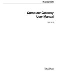
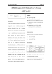
1.2 PROCESSOR GATEWAY ARCHITECTURE
The Processor Gateway (PG) consists of a software package and data link hardware that is
added to a 45000 computer, plus a Computer Gateway (CG), that is joined to the 45000 by
a TSDL data link. See Figure 1-1 for an overview of the Processor Gateway hardware and
software components.
The 45000 computer's base software includes either PMC or PMX. The PG software
extensions to PMC/PMX handle the details of communication between the 45000 and other
LCN nodes. Scheduled gathering or export of data values is controlled by user-generated
data tables. Provision is also made for user-written control programs to get or give LCN
data.
The Computer Gateway is a standard LCN node, housed in a 5-slot TDC 3000X chassis.
Its hardware components include an LCN interface board, an MCPU, memory, a power
supply, a communication interface board, and a TSDL data link to the 45000. Its memory
contains the standard TDC 3000 node-environment software along with CG-specific
application software and a user-defined database.
The CG database includes two data point types (ACIDP and CRDP) that are used for
controlling the scheduling of special application programs (called ACPs) in the 45000 and
for holding data to be exchanged between the 45000 and other nodes on the TDC 3000X
Local Control Network.
Processor Gateway User Manual
1-1
8/95
1.2
ACP
Interface
Routines
45000 Software
Environment *
45000
Data Communicator Program
Communication Handler
Processor
Gateway
76.8 KB
BSC 2780
Protocol
Communication Handler
Scheduler Program
CG Software
Environment*
CG
Communication Handler (LCN)
Local Control Network
* Software environments include Databases, data access mechanisms,
and other essential software.
Figure 1-1 — Processor Gateway Hardware and Software Structure
Processor Gateway User Manual
1-2
6682
8/95
1.3
1.3 REFERENCES
The following TDC 3000X publications contain additional information required to
understand functions of the Processor Gateway.
Title
Publication No.
Network Form Instructions
SW12-505
System Control Functions
SW09-501
Computer Gateway Forms
CG88-500
Computer Gateway Form Instructions
CG12-500
Computer Gateway
Parameter Reference Dictionary
Data Entity Builder Manual
CG09-540
Picture Editor Reference Manual
SW09-550
Hiway Gateway
Parameter Reference Dictionary
Hiway Gateway Control Functions
HG09-540
Control Language/Application Module
Reference Manual
Application Module
Parameter Reference Dictionary
Control Language/Application Module
Data Entry
AM27-510
SW11-511
HG09-501
AM09-540
AM11-585
Binder
Implementation/Startup &
Reconfiguration - 1
Implementation/Startup &
Reconfiguration - 2
Implementation/
Configuration Forms
Implementation/
Processor Gateway
Implementation/
Processor Gateway
Implementation/
Engineering Operations - 1
Implementation/
Engineering Operations - 2
Implementation/
Hiway Gateway - 1
Implementation/
Hiway Gateway - 1
Implementation/
Application Module - 2
Implementation/
Application Module - 1
Implementation/
Application Module - 2
45000/PMC/PMX Publications
Title
Section No.
S/T General Information
S/T Implementation
TOTAL Programming/1
TOTAL Programming/2
PMX III Implementation/1
PMX III Implementation/2
PMX III Configuration
FREETIME IV
FILES IV
FORTRAN IV
RTMOS (R170)
25-366
25-375
25-376
25-377
25-780
25-781
25-782
25-346
25-347
25-348
25-344
Processor Gateway User Manual
1-3
Binder
TDC-639
TDC-640
TDC-641
TDC-641
TDC-730
TDC-731
TDC-731
TDC-622
TDC-622
TDC-622
TDC-621
8/95
Processor Gateway User Manual
1-4
8/95
2
CONCEPTS AND MECHANISMS
Section 2
This section introduces you to the software features that have been added to PMC/PMX that
provides a simple, efficient interface to data in other devices on the TDC 3000 X Local Control
Network. It concludes with an overview of the steps required to install and test a program.
The primary use of the Processor Gateway is to enable the 45000 PMC/PMX system to
accomplish scheduled gathering of data from and the output of data to the LCN (through
the CG). Automatic processing of point data is specified by the user through preparation of
data tables that reside in the 45000. Additionally, the user can create application programs
that also access data on the LCN.
2.1 TDC 3000X DATA ACCESS
Because the TDC 3000X is a distributed system, its data is scattered among the various
LCN nodes. Each piece of data is assigned to a data owner (program) in the node where it
resides. Data can be addressed by the point_name.parameter character string (referred
to as its "external address") in a request broadcast to all nodes on the LCN. The data
owner responds with a numeric "internal address" that can be used for direct access to the
data. If it is necessary to access data on a remote LCN connected through a Network
Gateway, the point must be addressed as id\point_name.parameter, where id is the
remote system identifier.
If the 45000 always requested a piece of data by its "external address" the "internal
address" would need to be obtained each time. Time during LCN loading is saved by
having the 45000 obtain the "internal address" once, then save it each time the data is
requested. This is automatically done during the creation of special tables known as Data
Definition Tables (DDT) used for both scheduled and programmed point processing.
Current process values can be obtained from the CG, the Applications Module, or the
Hiway Gateway (data from Data Hiway boxes).
2.1.1 Role of Data Definition Tables
There are two types of Data Definition Tables: "named" DDTs provide an interface
between Application Programs and the TDC 3000X data points. “Scheduled” DDTs are
used to provide a direct interface between 45000 points and TDC 3000X data points, and
are not related to user-created programs.
Processor Gateway User Manual
2-1
8/95
2.1.1
Each Data Definition Table (DDT) specifies a set of data point parameter values to be
accessed and also indicates how each value is to be processed. (When parameter arrays are
accessed, individual elements of the array are specified separately.) To access LCN data, a
45000 program specifies which DDT is to be used and receives or provides arrays of point
parameter values.
Each named DDT contains only input points or output points; within each table the points
are grouped by data type (real, integer, ASCII, and enumeration). Individual point and
parameter names are specified along with individual point-value processing information.
The DDT is not part of a program; it is separately constructed and installed.
2.1.2 Role of CG-Resident Data Points
There are two types of CG-resident data points that can be associated with a program in the
45000.
• The Advanced Control Interface Data Point (ACIDP) has the multiple duties of ACP
execution control, of being a message buffer, and of providing Custom Data Segments
for storage of calculated values from the 45000 or other LCN nodes.
• The Calculated Results Data Point (CRDP) role is restricted to that of storage for
calculated values.
An ACP can have one ACIDP connection. If its ACIDP's Access Key value (established
when configured) permits, an ACP can write to any CG or Application Module data point
unless that point's access is limited to the Entity Builder.
2.2 SCHEDULED POINT PROCESSING
Automatic cyclic exchange of data between 45000 points and TDC 3000X data points is
controlled by the contents of "scheduled" DDTs. These DDTs are used by an internal ACP
named PGDCP.
To establish scheduled point processing you connect PGDCP to an ACIDP of your choice
in each CG (see paragraph 6.1.1.1) and add points to the "scheduled" DDTs (one exists for
each of two base-scanning frequencies) For each point to be accessed, you need to define
the following:
•
•
•
•
Point and parameter names of the LCN data point
Point record name and parameter name of the associated 45000 point
Schedule frequency, rate, and phase
Value processing such as input limit checks.
Details of DDT preparation are found in Section 4.
Processor Gateway User Manual
2-2
8/95
2.3
2.3 PROGRAMMED POINT PROCESSING
A user application program that communicates with other LCN nodes is referred to as an
Advanced Control Program (ACP). It executes as a FREETIME IV program and uses
special interface subroutines that simplify the tasks required in the exchange of data with
other TDC 3000X nodes and boxes. These interface subroutines can be called from either
Fortran or PAL. Specifics of the subroutine calls are found in Section 3, "User Interface
Subroutines," but a brief outline of their use is as follows.
Execution of ACPs can be divided into three stages, each with its related interface routines:
Setup stage—The "Get ACP Status" subroutine (GETSTS) obtains information that
indicates why the ACP has been activated, thereby establishing what actions may be
necessary at this specific activation.
Run stage—Subroutines for exchange of data with LCN-resident modules are used to
–Get LCN data (GETDTA)
–Store LCN data (STRDTA)
–Receive LCN messages (GETMSG)
–Send LCN messages (SNDMSG)
Cleanup stage—The "Termination" interface subroutine (PRGTRM) provides for both
normal and abnormal program termination, and normally is the last executing statement
of an ACP.
NOTE
Other nodes on the LCN cannot directly access data in the 45000. Other nodes can,
however, read data stored by ACPs in the CG's ACIDP and CRDP data points.
The definition of what LCN point parameters are to be accessed is contained in "Named"
DDTs that are referenced in the GETDTA and STRDTA calls. Details on the creation of
Named DDTs is found in Section 4 of this manual.
An ACP can send character-string messages to all operator stations within its operating area
by using the SNDMSG interface subroutine. An option to wait for operator confirmation is
provided.
Other devices on the LCN can send character-string messages to an ACP through its
connected ACIDP. Messages are held by the CG pending an ACP call of the GETMSG
interface routine. Presence of a pending message at the CG is detected for the ACP by the
GETSTS interface subroutine.
Processor Gateway User Manual
2-3
8/95
2.3.1
2.3.1 ACP Installation Modes
ACP scheduling and capabilities are affected by its manner of installation. Those ACPs
that are "connected" to an ACIDP are normally scheduled by the CG and use all six
interface subroutines. Those ACPs that are not ACIDP-connected are scheduled by the
45000 and can use only the Get Data interface.
Tables 2-1 and 2-2 depict the limitations on ACPs as determined by your installation
choices.
Table 2-1—ACP Scheduling Capabilities
ACP is not
connected
to an ACIDP
ACP is
connected
to an ACIDP
no
no
no
no
no
yes
yes
yes
yes
yes
yes
yes*
ACP can be initiated by
- CG - Cyclic
- CG - Periodic
- Operator Demand
- Process Special
- Message waiting at CG
- 45000
*Can use only the Get Data interface.
Table 2-2—Interface Subroutines Effective
ACP is not
connected
to an ACIDP
- Get Data
- Store Data
- Get Message
- Send Message
- Get ACP Status
- ACP Termination
yes**
no
no
no
no
no
ACP is
connected
to an ACIDP
yes**
yes
yes
yes
yes
yes
**Test values are substituted for live input data when specified in
the referenced Data Definition Table.
Processor Gateway User Manual
2-4
8/95
2.3.2
2.3.2 ACP Scheduling by the CG
NOTE
Because the INH_STAT parameter is initially set to the "inhibit" state, first-time CG scheduling
of an ACP cannot begin until after operator action "permits" operation through the ACIDP's
Detail Display or a custom display allows access to that parameter. See the CG Parameter
Reference Dictionary for details.
2.3.2.1 Program Activation
There are five choices for normal-mode scheduling of ACPs by the CG: cyclic, periodic,
demand, cyclic/demand, and periodic/demand.
Periodic and Cyclic Scheduling
Periodic programs first run at a specified daily start time (STIME) and thereafter run at a
specified time interval (RTPERIOD). The STIME value must be less than RTPERIOD.
Example 1: RTPERIOD = 24:00:00 STIME = 17:00:00
This program runs each day at 17:00:00 hours.
Example 2: RTPERIOD = 08:00:00 STIME = 07:00:00
This program runs each day at the following times: 07:00:00, 15:00:00 and 23:00:00.
Cyclic programs run at a specified time interval (RTPERIOD).
Example 3: RTPERIOD = 00:10:00
This program runs every 10 minutes.
A Periodic or Cyclic program runs immediately upon a CG initialization event (see
subsection 5.4.1) if in Normal Mode and its ACIDP was built with RUN_INIT = ON. If
RUN_INIT = OFF, a Cyclic program first runs at RTPERIOD seconds following the
initialization event and a Periodic program first runs at the time of day specified by STIME.
The time-interval range for both periodic and cyclic programs is 10 seconds to 24 hours.
The subcategories of periodic/demand and cyclic/demand programs also allow for
activation by process-operator demand from the Universal Station.
Operator Demand
An ACP can be activated from a Universal Station through the PROCESS target on its
ACIDP's detail display if its activation type is demand, cyclic/demand, or periodic/demand.
You can also create custom displays that provide for the activation of ACPs (by setting the
OPER_DMD parameter of the ACIDP to ON). See the Picture Editor Reference Manual in
the Implementation/Engineering Operations - 2 binder for custom display-building details.
Operator demand is also used in the recovery of an ACP from the Abort state. See
OPER_DMD in the CG Parameter Reference Dictionary in the Implementation/Computer
Gateway binder, for details.
Processor Gateway User Manual
2-5
8/95
2.3.2
PPS Activation
A connected ACP is immediately activated following a store data of ON to its ACIDP's
PPS parameter from another ACP, an HG (Event Initiated Processing), or an AM (CL
"Initiate" statement). This activation method is also used by the CG upon receipt of a
Message to an ACP. Process special event-activation is independent of scheduling type.
2.3.2.2 Program Termination
The PRGTRM interface routine is used to inform the CG that the ACP has gone from
"Run" to "Off/Delay" state or to "Abort" state. Once in "Abort" state, the CG suspends
periodic or cyclic scheduling of the ACP. Reactivation of the ACP requires operator
demand or a 45000 restart.
A program abort alarm is sent to the LCN's Real Time Journal by the CG whenever an
ACP terminates in "Abort" state.
For those instances when you need the 45000 to control an ACP's execution, and also need
the ACP full input and output capabilities, attach the ACP to an ACIDP without the
Program Termination interface. Therefore, after the first activation, the CG treats the ACP
as busy and ignores any scheduling events.
2.3.2.3 Program Inhibit
The process operator can inhibit or permit an ACP's activation by the CG by selecting the
INH_STAT target on the associated ACIDP's Universal Station Detail Display.
Optionally, the operator can construct a custom display that performs this function by a
store of INHIBIT/PERMIT to the ACIDP's INH_STAT parameter. If the ACP is already
in the "Run" state when the inhibit request is received, any outputs are blocked at the CG.
2.3.3 Operator Interfaces to ACP
Different types of operator access to operation of the ACP are provided at the TDC 3000X
Universal Station (process operator) and at the 45000 programmer's terminal (computer
operator).
2.3.3.1 Process Operator Interfaces
The process operator can affect ACP operation from the Universal Station only when that
ACP is connected to an ACIDP.
The process operator can view ACP status, inhibit ACP operation, demand immediate ACP
execution (if permitted for that ACP), view ACIDP and CRDP point parameter values, and
view or change ACIDP and CRDP Custom Data Segment values. The operator's ability to
change Custom Data Segment values is controlled by access restrictions established at point
building time.
ACP-initiated screen messages can specify operator confirmation.
Processor Gateway User Manual
2-6
8/95
2.3.3
2.3.3.2 Computer Operator Interfaces
From a 45000 terminal, you communicate with an ACP as with any other FREETIME IV
program; by using PGBLD, you can view ACP status and make or break its ACIDP
connection.
2.3.4 ACP Execution Example
The following is a simplified example of ACP execution. It is based on assumptions of
ACIDP connection and demand scheduling. See Figure 1-1 for an illustration showing
relationships of the referenced software functions.
At a Universal Station
1. The ACP is demanded through its ACIDP's Detail Display
In the CG
2. The CG Scheduler program creates and sends a message requesting a turn on of the
ACP.
In the 45000
3. The PG Data Communicator Program (PGDCP) activates the ACP.
4. The ACP does initial housekeeping (GETSTS).
5. The ACP calls GETDTA.
6. The ACP is suspended. PGDCP creates a message based on the DDT referenced
and sends it to the CG.
In the CG
7. The CG routes the message to the Data Owner (via the LCN Communication
Handler if elsewhere on the LCN).
8. When the return message is available from the Data Owner, the CG sends it to the
45000.
In the 45000
9. The interface routine writes the retrieved information into storage allocated by the
ACP and PGDCP "wakes up" the suspended ACP.
Steps 5-9 are repeated for additional interface routine calls.
10. The ACP acts on the data, then goes into its cleanup stage (PRGTRM).
Processor Gateway User Manual
2-7
8/95
2.4
2.4 PROCESSOR GATEWAY SUPPORT FUNCTIONS
There are three major entities that provide LCN data access support in the 45000:
• User Interface Subroutines
• The PG Table Builder Program (PGBLD)
• The Data Communicator Program (PGDCP)
The User Interface Subroutines are listed below along with paragraph number references to
where detailed information is found in this manual.
Paragraph
Interface Description
Name
3.2
3.2.1
3.2.2
Data Transfers
Get Data
Store Data
GETDTA
STRDTA
3.3
3.3.1
3.3.2
Text Message Transfers
Get Message
Send Message
GETMSG
SNDMSG
3.4
3.4.1
3.4.2
ACP Execution Support
Get ACP Status
ACP Termination
GETSTS
PRGTRM
The PG Table Builder Program is used to:
•
•
•
•
Create Data Definition Tables from templates
Connect/disconnect ACPs to ACIDPs
List Directory Entries
Delete Directory Entries
The Data Communicator Program is used to:
•
•
•
•
•
Control the execution of scheduled DDTs
Perform required value processing
Handle all 45000-LCN data conversions
Communicate with the CG over the data link
Issues Run-Time Error Messages (Appendix B)
Processor Gateway User Manual
2-8
8/95
2.5
2.5 IMPLEMENTATION STEPS
The exact sequence varies depending on specific circumstances, but all the following steps
are necessary to complete the installation of an ACP. Number references included in the
following headings point to later sections in this manual where more detailed information is
found.
CAUTION
Be sure to initiate a checkpoint of the CG any time its database is modified by the addition or
deletion of points, by ACP connect or disconnect, etc.; otherwise, the CG database reverts to
the previous contents during its next restart.
2.5.1 Configuring the CG
At the TDC 3000X Universal Station, modify the system NCF to include the CG. Refer to
the System Configuration Guide as a starting point if this procedure is unfamiliar. As part
of LCN Nodes Configuration, assign one or more Process Units to the CG (see Network
Form Instructions and Appendix D of this manual for additional information).
With software before Rel 200, the number of data links (1) and baud rate (76800) are
selected during node configuration. Starting with Rel 200, however, those parameters and
some additional CG configuration entries are made through the CG CONFIGURATION
display (entered from the CM BUILD AND CONFIGURATION menu). Use the default
values for all entries except "Number of Links" which must be changed to 1 Link. See the
CG Parameter Reference Dictionary for definitions of the configuration entries and for the
normal default values.
On completion of R200 CG configuration (or configuration change), you must demandcheckpoint the CG, then shut down and restart the node in order for the changes to take
effect.
2.5.2 Preparing CG-Resident Data Points (5)
At a TDC 3000X Universal Station, use the CL compiler to define any Custom Data
Segments, then build the ACIDP and CRDP points. Installed ACIDP and CRDP parameter
values can be displayed at a Universal Station (Point Detail Display).
2.5.3 Preparing Data Definition Tables (4)
At the 45000 terminal, build the Data Definition Tables using PGBLD. Any referenced
points must be built and be accessible through the data owner before the table build can be
completed. ACP references to nonexistent or incomplete DDTs are rejected by the interface
subroutines.
Processor Gateway User Manual
2-9
8/95
2.5.4
2.5.4 Compiling ACP
At the 45000 terminal, compile the ACP. Each ACP is separately compiled and linked
through standard 45000 programs.
2.5.5 Installing ACP (4)
At the 45000 terminal, use PGBLD to install the ACP.
Processor Gateway User Manual
2-10
8/95
3
USER-PROGRAM INTERFACES
Section 3
This section discusses each of the program interfaces that provide necessary services that enable
PAL or Fortran programs to communicate with other nodes on the TDC 3000X Local Control
Network.
3.1 INTRODUCTION TO USER INTERFACE ROUTINES
The immediately following paragraphs cover information that relates to general
characteristics of user-interface calls.
Beginning at subsection 3.2, details on each of the interface calls are given. Each call is
shown as it would appear in a Fortran program.
3.1.1 Common Characteristics
• The Get Data and Store Data routines returns status information, both on the call itself
and for each accessed point or array.
• All arrays are of a single dimension.
• Each call to one of these interfaces must include all defined parameters in the order
shown. All parameters are passed by reference (location), not by value.
• To use the Get Data or Store Data interfaces, you must specify the data type assigned to
each data point parameter being accessed. If state values are used, you also need to
prepare tables of enumeration values associated with predefined parameter types and
your custom data segments. In the 45000, state values for enumerations are expressed
as integer pointers to these enumeration set tables.
For information on enumeration sets assigned to the predefined parameter types, see the
Application Module, Hiway Gateway, and Computer Gateway Parameter Reference
Dictionaries.
3.1.2 Data Formats
Data conversions that may be required because of differences between the 45000 and LCN
data formats are performed by PGDCP. The following conventions must be observed in
the 45000 to ensure data compatibility.
Reals—24-bit
45000 floating point
Integer—Maximum value range is -32767 to 32767
Ascii—24-byte character string
Enumeration—Integer values as assigned through enumeration set definition tables
(see subsection 4.5.1)
Ordinal—Integer values representing the defined ordinal position (0-n) of enumeration
values.
Processor Gateway User Manual
3-1
8/95
3.1.3
3.1.3 Compatibility of ACP with Its DDTs
Because each ACP and its Data Definition Table(s) are built separately, the system cannot
enforce compatibility between an ACP and its DDT(s). That responsibility is up to you.
In particular, it is vital that the dimensions set for data-receiving arrays be large enough to
accommodate the maximum data amounts permitted by the named DDT.
Specific points to remember for Get Data and Store Data are:
• Dimensions set for each array must be equal to or greater than the point count in the
referenced DDT. If the program arrays are too small, data or code may be corrupted
(Get Data) or inappropriate data may be exported (Store Data).
• The dimension values for status table arrays must be equal-to or greater-than the total
number of points of all types in the referenced DDT because this array is to receive a
status code for each returned value, positioned according to its location in the DDT.
3.1.4 Commonly Encountered Problems
• Failure to specify array sizes that match DDT sizes.
• Failure to use the PRGTRM call as the last statement in an ACP (unless subsequent
activation is to be by the 45000, not the CG).
3.1.5 Error Detection by Interface Calls
The interface calls detect two types of errors and return information on them to the ACP
through call parameter values.
The RETURN_STATUS parameter shows whether the request was processed
successfully, and if not, what error type was involved. Some typical errors flagged by
the return status are:
•
•
•
•
LCN access problems or data link failure
ACP installation or mode problems
Data problems in the call or with a referenced DDT
Call rules violations
The STATUS_TABLE parameter points to an array containing a data status code for
each point parameter accessed. These status codes show whether there have been any
data access errors that would invalidate a requested get or store operation for that point
parameter. There are over 200 different data access error codes that can be returned as
described in Appendix A.
Data transfer calls employ both RETURN_STATUS and STATUS_TABLE
PARAMETERS, while text message transfers use only RETURN_STATUS. See the
individual calls for more information.
Violations of RTMOS/Files IV rules result in the ACP being aborted, and an error message
is logged at the 45000 console terminal. See the RTMOS user documentation for message
interpretation.
Processor Gateway User Manual
3-2
8/95
3.2
3.2 DATA TRANSFERS
The interface routines in this group require the use of Data Definition Tables (DDT) that
specify which points are to be accessed and what pre/post processing is to be done on data
values. See Section 4 for DDT preparation and installation details.
Individual elements of parameter arrays (but not whole arrays) can be specified in the DDT.
3.2.1 Get Data Interface
This routine fetches data from the CG or elsewhere on the LCN. The specification of
which data is to be fetched is contained in the Data Definition Table referenced by the call.
Any errors encountered during execution of the routine as well as individual point data
errors are returned to the calling program.
3.2.1.1 Fortran Subroutine Call for Get Data
CALL GETDTA
(DATA_TABLE_NAME, REAL_VALUES_ARRAY, INTEGER_VALUES_ARRAY,
ASCII_VALUES_ARRAY, ENUM_ARRAY, STATUS_TABLE,
RETURN_STATUS)
3.2.1.2 Parameter Definitions for Get Data
DATA_TABLE_NAME—The name of a packed array of ASCII characters that contains the
name of the input Data Definition Table to be used. The table name is a
maximum of eight characters long.
REAL_VALUES_ARRAY—The name of a single-dimension array into which the fetched
Real values are to be stored. Bad values are returned as NaN (-0).
INTEGER_VALUES_ARRAY—The name of a single-dimension Integer array into which the
fetched Integer values are to be stored. Bad values are returned as NaN (-0).
ASCII_VALUES_ARRAY—The name of a packed array into which fetched ASCII strings are
to be stored. Bad values are returned as strings of 24 question marks.
ENUM_ARRAY—The name of a single-dimension Integer array into which fetched
Enumeration or Ordinal values are to be stored.
STATUS_TABLE—The name of a single-dimension Integer array for the storage of point-
related error/status information. A status code is returned for each requested
value. See Appendix A for a listing of Data Access error/status codes.
RETURN_STATUS—The name of an Integer variable where the request completion status is
to be stored. The assigned meanings are:
0 – Normal return. Request successfully completed.
1 – Referenced DDT does not exist
3 – Unable to access the CG
4 – Wrong execution state
5 – Request completed, but errors exist in data
10 – Get-table empty
16 – Specified ACIDP not found
Processor Gateway User Manual
3-3
8/95
3.2.2
3.2.2 Store Data Interface
This routine sends data to points in the CG or elsewhere on the LCN. The specification of
what points are to receive data is contained in the Data Definition Table referenced by the
call. Errors encountered during execution of the routine, as well as individual point data
errors, are returned to the calling program.
To use this call, the ACP must be connected to an ACIDP with read/write access. See the
System Control Functions Manual for other write access restrictions.
3.2.2.1 Fortran Subroutine Call for Store Data
CALL STRDTA
(DATA_TABLE_NAME, REAL_VALUES_ARRAY, INTEGER_VALUES_ARRAY,
ASCII_VALUES_ARRAY, ENUM_ARRAY, STATUS_TABLE,
RETURN_STATUS)
3.2.2.2 Parameter Definitions for Store Data
DATA_TABLE_NAME—The name of a packed array of ASCII characters that contains the
name of the output Data Definition Table to be used in the "Store Data"
operation. The table name is a maximum of eight characters long.
REAL_VALUES_ARRAY—The name of a single-dimension array that contains the Real
values to be stored.
INTEGER_VALUES_ARRAY—The name of a single-dimension Integer array that contains
the Integer values to be stored.
ASCII_VALUES_ARRAY—The name of a packed array that contains the ASCII strings to be
stored.
ENUM_ARRAY—The name of a single-dimension Integer array that contains the
Enumeration or Ordinal values to be stored.
STATUS_TABLE—The name of a single-dimension Integer array for the storage of returned
point-related error/status information. A status code is returned for each
requested store value. See Appendix A for a listing of Data Access error/status
codes.
RETURN_STATUS—The name of an Integer variable where the request completion status is
to be stored. The assigned meanings are:
0 – Normal return. Request was successfully completed.
1 – ACP Reference not found
3 – Unable to access the CG
4 – Wrong execution state
5 – Request completed, but errors exist in data
6 – Specified ACIDP not found or ACP not connected to an ACIDP
9 – Access key incorrect
15 – ACIDP not in RUN state
Processor Gateway User Manual
3-4
8/95
3.3
3.3 TEXT MESSAGE TRANSFERS
The two interface routines in this group are used to send and receive character string
messages over the LCN.
3.3.1 Get Message Interface
This routine is used to fetch a character-string message held in a CG buffer for this
program's ACIDP. The message presence is determined as the result of a Get ACP Status
request.
3.3.1.1 Fortran Subroutine Call for Get Message
CALL GETMSG (TEXT_ARRAY, TEXT_ARRAY_SIZE, RETURN_STATUS)
3.3.1.2 Parameter Definitions for Get Message
TEXT_ARRAY—The name of a packed array of characters where the message is to be
stored (must provide for up to 120 ASCII characters).
TEXT_ARRAY_SIZE—The name of an Integer variable that specifies the maximum number
of characters expected (120-character limit).
RETURN_STATUS—The name of an Integer variable where the request-completion status
code is to be stored. The assigned meanings are:
0 – Normal return. Request was successfully completed.
1 – Request completed, but trailing characters in excess of specified
Text_Array_Size have been deleted.
2 – No message was pending.
3 – Not defined.
4 – Request was successfully completed. A second message is now
queued at the ACIDP.
5 – Request completed with trailing characters deleted. A second message
is now queued at the ACIDP.
6 – Valid ACIDP not found.
15 – ACIDP not in correct execution state.
3.3.2 Send Message Interface
This routine is used to send a message to all operator stations assigned to the same unit as
this program's ACIDP. A request to wait for operator confirmation is optional. If operator
confirmation is requested, execution of the requesting program is suspended until either the
confirmation occurs or until its specified wait-time expires. The requesting program
receives an indication of whether confirmation or a time out occurs.
Processor Gateway User Manual
3-5
8/95
3.3.2
3.3.2.1 Fortran Subroutine Call for Send Message
CALL SNDMSG
(TEXT_ARRAY, MESSAGE_SIZE, CONFIRM, WAIT_TIME,
DESTINATION, RETURN_STATUS)
3.3.2.2 Parameter Definitions for Send Message
TEXT_ARRAY—The name of a packed array of characters that contains the message to be
sent.
MESSAGE_SIZE—The name of an Integer variable that specifies the number of characters
to be transmitted. The maximum number of characters depends on message
destination: 60 for CRT displays, 72 for printing, and 120 for HM archiving.
Messages over the maximum number of characters are truncated. All messages
are archived.
CONFIRM—The name of a logical variable that when TRUE (integer 0) specifies that a
message confirmation is requested. Note that this parameter is treated as
FALSE (integer 1) if the message destination is printer only.
WAIT_TIME—The name of an Integer variable (0 to 3600) that specifies the number of
seconds the system is to wait for confirmation before returning control to the
requesting program with a no "confirm" return status. (Allow for a built-in time
lag of up to 10 seconds.) The Wait Time parameter is ignored if the Confirm
parameter is set to OFF or the message destination is printer only.
DESTINATION—The name of an Integer variable that specifies where the message is to be
sent, as follows:
0 – CRT only
1 – Printer only
2 – Both
RETURN_STATUS—The name of an Integer variable where the request-completion status is
to be stored. The assigned meanings are:
0 – Normal return. Request was successfully completed (and, if
requested, confirmed).
2 – Message could not be sent.
3 – Unable to access the CG.
4 – Message was sent, but wait time elapsed with no confirmation.
6 – Valid ACIDP not found.
15 – ACIDP not in correct execution state.
Processor Gateway User Manual
3-6
8/95
3.4
3.4 ACP EXECUTION SUPPORT
These interface routines affect the orderly execution and termination of an ACP.
3.4.1 Get ACP Status Interface
This routine fetches a value that enables the requesting program to determine why the
system has turned it on.
3.4.1.1 Fortran Subroutine Call for Get ACP Status
CALL GETSTS
(ACT_STAT)
3.4.1.2 Parameter Definitions for Get ACP Status
ACT_STAT—The name of an Integer variable (1-7) that receives the activation reason, as
follows:
1 – Initialization event
2 – Message waiting
3 – Operator demand
4 – Process Special
5 – Scheduled turn on (periodic or cyclic)
6 – Not used
7 – Initiated by 45000
3.4.2 ACP TERMINATION INTERFACE
This routine terminates the execution of the calling ACP. It normally is the last operating
statement if the ACP is attached to an ACIDP (see subsection 2.3.2.2 for the exception). A
termination status code is stored in the associated ACIDP's ABORTCOD parameter. If an
ACP is aborted by the operating system, a system-assigned abort code is stored.
The termination code assigned by this call can be viewed at a Universal Station (see the
definitions for ABORTCOD and EXECSTAT in subsection 5.4.1) but in a revised form.
The integer value assigned here is translated into four hexadecimal digits (0000 to 00FF).
Thus, an ACP-assigned abnormal termination code of 15 appears at the Universal Station
display as 000F.
The execution state of an ACIDP can be changed from ABORT to normal by operator
demand through a Universal Station. See OPER_DMD in the Computer Gateway
Parameter Reference Dictionary for additional details.
Processor Gateway User Manual
3-7
8/95
3.4.2
3.4.2.1 Fortran Subroutine Call for ACP Termination
CALL PRGTRM
(TERMINATE_CODE)
3.4.2.2 Parameter Definitions for ACP Termination
TERMINATE_ CODE—The name of a variable of type Integer that must contain zero or a
positive value (1 to 255). Zero value indicates normal termination. Nonzero
values are user-specified codes for non-normal termination (abort).
Processor Gateway User Manual
3-8
8/95
4
USING THE PG TABLE BUILDER
Section 4
This section explains how you prepare the special tables that are used in getting or storing data for
PG functions.
4.1 TABLE BUILDER OVERVIEW
The PG Table Builder (PGBLD) is used to build the Scheduled and Named Data Definition
Tables used to control the exchange of data between the 45000 and LCN nodes. It also
provides for enumeration set definition and table maintenance functions (list and delete).
Additionally, the Table Builder is used to connect and disconnect ACPs to ACIDPs.
The steps are:
1. Copy or add one or more images of one or more types of predefined "templates" from
FILES IV files.
2. Edit the templates to include parameter values.
3. Invoke PGBLD to build a table or to take other specified actions.
There are 13 types of templates that are used alone or in combinations.
See subsection 4.6 for more information on these execution steps.
4.1.1 Named DDTs
The templates used to build Named DDTs are:
-Define DDT Name (required)
-Real Input
-Integer Input
-ASCII Input
-Enumeration Input
-Ordinal Input
-Real Output
-Integer Output
-ASCII Output
-Enumeration Output
-Ordinal Output
Each Named DDT can contain only input (Get Data) or output (Store Data) parameters.
Points within an input or output Data Definition Table can be of more than one data type,
but they must be grouped by type and a type group cannot repeat within a DDT. Table 4-1
illustrates characteristics of these table types.
CAUTION
You must not include both Enumeration and Ordinal data types in the same DDT.
Processor Gateway User Manual
4-1
8/95
4.1.2
Table 4-1 — Named DDT Table Types and Data Types
Table Types
Allowed Data Types
PT Count Max
Input
Real
Integer
ASCII
Enumeration or Ordinal
300
Output
Real
Integer
ASCII
Enumeration or Ordinal
300
4.1.2 Scheduled DDTs
The two Scheduled DDTs (PGCSC1 and PGCSC2) employ most of the same templates as
Named DDTs, but there are significant differences in how they are prepared and used.
• You do not
specify a table name for Scheduled DDTs, the parameter value SCHEDULE BASE does
this.
• You can enter (add) one point or groups of points at a time.
• Points can be randomly entered without consideration of point type, input/output, or
Schedule Base assignment.
Details of Scheduled DDT point assignments are found in the template descriptions that
follow and in the template comment fields.
The templates used to build Scheduled DDTs are:
-Real Input
-Integer Input
-Enumeration Input
-Ordinal Input
Processor Gateway User Manual
-Real Output
-Integer Output
-Enumeration Output
-Ordinal Output
4-2
8/95
4.2
4.2 DDT TEMPLATE TYPES
There is one FILES IV file for each template type. The file name contains a mnemonic that
identifies its function. For example, the template used to build Real Input data points is in
the file named DDTRI.PGTMPL.MEDIA.
Following is a list of the template names followed by type or function and a paragraph
number reference:
DDTRI.PGTMPL.MEDIA
DDTRO.PGTMPL.MEDIA
DDTII.PGTMPL.MEDIA
DDTIO.PGTMPL.MEDIA
DDTAI.PGTMPL.MEDIA
DDTAO.PGTMPL.MEDIA
DDTEI.PGTMPL.MEDIA
DDTEO.PGTMPL.MEDIA
DDTOI.PGTMPL.MEDIA
DDTOO.PGTMPL.MEDIA
DEFES.PGTMPL.MEDIA
DEFDDT.PGTMPL.MEDIA
INSACP.PGTMPL.MEDIA
DELETE.PGTMPL.MEDIA
LIST.PGTMPL.MEDIA
Real Input
Real Output
Integer Input
Integer Output
ASCII Input
ASCII Output
Enumeration Input
Enumeration Output
Ordinal Input
Ordinal Output
Define Enumeration Set
Define DDT Name
Install ACP
Delete from Directories
List Directory Contents
4.3.1
4.4.1
4.3.2
4.4.2
4.3.3
4.4.3
4.3.4
4.4.4
4.3.5
4.4.5
4.5.1
4.5.2
4.5.3
4.5.4
4.5.5
Templates are in free form, and use the "blank" character to separate fields. Each entry in a
template is in the general form "item = value." The "value" field cannot contain embedded
blanks after the first nonblank character and must be followed by one or more blanks. The
"item" field can use one or more blanks to separate words (e.g., SCHEDULE
BASE).
Comments are included to help explain template function and are defined by the character
"*" (you may add additional comments if you wish). If "*" appears in the first column of a
line, the entire line is treated as a comment. Within a line, a comment must both start and
end with "*." An example of comment use within a template follows:
*1*
*1*
SCHEDULE
BASE= *I3*
POINT RECORD= *A9*
RATE=*I3* PHASE= *I3 OR ANY*
PARAMETER= *A9*
PSP?= N
*Y/N*
When building Named DDTs, this line pair is left as a comment (or may be deleted), but
when building Scheduled DDTs the "*1*" at the beginning of each line must be removed,
and the required parameter data inserted (replaces comment field following "="). The
"*I3*" and "*A9*" comment fields indicate the data type and maximum number of
characters accepted for value entries. The following conventions are used in the comments
to identify value types:
*F*
*In*
*Ann*
*text*
- Real value
- Integer value not to exceed "n" decimal digits
- An ASCII string not to exceed "nn" characters
- Where *text* defines the acceptable"value" set
Processor Gateway User Manual
4-3
8/95
4.2.1
4.2.1 Definitions of Template Value Entries
The following define the formats and significance of specific value entries to be made to the
templates. Template descriptions begin at subsection 4.3.
ACIDP
Name of the ACIDP associated with the ACP. This is a
TDC3000X LCN point name and must be from one-to-eight
characters long and begin with "A..Z" or "0..9." Characters
within the point name must be "A..Z", "0..9" or "_" (underscore).
All-numeric names are not permitted. Consecutive underscore
characters or trailing underscores are not permitted. The first
trailing "blank" character signals end of the point name. An
entered "-" (hyphen or minus sign) is interpreted as (and is
replaced by) an underscore.
ACP
The Advanced Control Program name, from one to six characters
beginning with "A..Z." Characters within the name consist of
"A..Z" and "0..9."
ALGOA
This specifies the type of scaling calculation to be performed on
the input value (V). The accepted algorithms are:
0 = no calculation
1 = V+K1
2 = V-K1
3 = V*K1
4 = V÷K1
5 = V*K1+K2
BV SUBST?
If the input is a BAD VALUE, this option permits a constant to be
substituted for it.
CIU
A 45000 can be connected to more than one CIU (CG), and this
item defines which CG (1..3) is used to access the data point.
CLAMP LOW?
CLAMP HI?
When selected, these options "clamp" the value at the limit if the
entered limit is exceeded. If clamping is not selected, values
failing limit checks are set to bad.
CONSTANT
When BV SUBST? is selected, this is the substitution value.
DATA TABLE
The DDT name, one to eight characters consisting of "A..Z" and
"0..9."
Processor Gateway User Manual
4-4
8/95
4.2.1
ENUMERATION
ENUMERATION
SET ID
The enumeration ASCII value consisting of from one to eight
characters.
The name of an enumeration set to be used with the designated
point parameter to provide transformation between TDC 3000X
and 45000 data bases. From one to eight characters, "A..Z" and
"0..9."
K1, K2
Constant values used in the scaling algorithm calculations.
Required only if used by the selected algorithm.
LF SUBST?
If the CG data link fails, the input value defaults to -0 unless Y is
selected. If Y is selected, the previous value is retained.
LIMIT CK?
Permits the value to be limit checked after any scaling calculations.
If this option is selected (Y), a low limit and/or high limit must be
entered.
LOW LIMIT
HIGH LIMIT
Limit values used with the LIMIT CK? option. Only the limit(s)
to be checked need be entered.
ORDINAL
Position (0-n) of an enumeration in an assigned set of values.
PARAMETER
May refer either to a TDC 3000X LCN or 45000 point parameter,
depending on context within the DDT type.
TDC 3000X: One to eight characters, beginning with "A..Z."
Characters within the parameter name must be "A..Z", "0-9" or
" " (underscore). All-numeric names are not permitted.
Consecutive underscore characters or trailing underscores are not
permitted. The first trailing "blank" character signals the end of
the parameter name. An entered "-" (hyphen or minus sign) is
interpreted as (and is replaced by) an underscore.
Example: PV
SP
OP
45000: One to nine characters consisting of "A..Z", "0-9." The
first trailing "blank" character signals end of the parameter name.
Example: PV
SP
Processor Gateway User Manual
4-5
8/95
4.2.1
Parameter names of either variety can be subscripted (to allow
accessing an individual element of a parameter array) by enclosing
the subscript value in parentheses immediately following the
parameter name.
Example: XYZ(2)
PHASE
When RATE is greater than SCHEDULE BASE, PHASE
specifies an offset in seconds from the SCHEDULE BASE time.
Enter the default value ANY to have the builder assign the point to
the least full phase. Otherwise, this value must be zero or an exact
multiple of the SCHEDULE BASE value.
Example: SCHEDULE BASE = 30
RATE = 120
PHASE = 60
This example schedules an entry in the 30-second DDT tables that
are processed every 120 seconds starting 60 seconds into the base
processing period.
POINT NAME
Represents a TDC3000X LCN point name that must be from one
to eight characters long and begin with "A..Z", "0..9" or "$."
Characters within the point name must be "A..Z", "0..9" or " "
(underscore). All-numeric names are not permitted. Consecutive
underscore characters or trailing underscores are not permitted.
The first trailing "blank" character signals end of the point name.
An entered "-" (hyphen or minus sign) is interpreted as (and is
replaced by) an underscore.
Example: AM5HGDDC
095HGSWT
$05HGDDC ("$" designates a system-reserved point
name)
POINT RECORD
Represents a 45000 point name that must be from one to nine
characters long. Characters in the point record name must be
"A..Z" and "0..9."
Example: GGD007
09FT05
PSP?
When set Y, this option forces demand processing (process
special) of the 45000 point after the input value is stored to the
specified parameter of the point.
Processor Gateway User Manual
4-6
8/95
4.2.1
RATE
Specifies the actual frequency (in seconds) of processing for that
point parameter. This value must be an exact multiple of the
SCHEDULE BASE value.
SCHEDULE BASE
Used to identify a scheduled DDT. The SCHEDULE BASE value
is one of two DDT Scheduler processing rates (PGCSC1 and
PGCS2) configured for your system (see subsection 6.1.2.1).
The value entered must match one of these configured rates.
STATUS
This option defines the ACP program execution status. Valid
entries are:
N - Normal
T - Test
R - Restricted
STORE?
This option applies only to values of type Real. It establishes
whether the value—after scaling calculations—is to be stored to
the TDC 3000X data point. The selections are
G - store only if the value is good (do not store if not good)
B - store whether the value is good or bad
D - do not store the value whether good or bad
TEST VALUE
When USE TEST? is selected, this value is substituted.
USE TEST?
While set Y, a test value is substituted for the input value of a
point in a named or scheduled DDT.
VALUE
An integer representing the internal 45000 value assigned to the
associated ASCII enumeration value. Enumeration values are
fetched from and stored to the TDC 3000X as ASCII values;
however, these values are maintained in the 45000 as integer
values. This transformation is performed by the input and output
processor as defined by the ENUMERATION SET.
Processor Gateway User Manual
4-7
8/95
4.3
4.3 INPUT TABLE TEMPLATES
4.3.1 Input-Real
Used to build a DDT table entry to "fetch" a real value from a TDC 3000X point parameter.
Template File Name: DDTRI.PGTMPL.MEDIA
Template form:
*
* *
DATA DEFINITION TABLE TEMPLATE FOR "REAL INPUT"
*
INPUT TABLE, DATA TYPE= REAL
POINT NAME= *A8*
PARAMETER= *A8*
CIU=1 *I1*
* OPTION: SELECT BY REMOVING THE "*1*" FOR SCHEDULING.
*1*
SCHEDULE
BASE= *I3* RATE=*I3* PHASE= *I3 OR ANY*
*1*
POINT RECORD= *A9*
PARAMETER= *A9*
PSP?= N *Y/N*
*1*
LF SUBST?= N *Y/N*
USE TEST?= N *Y/N* TEST VALUE= *F*
BV SUBST?= N *N-No,
C-CONSTANT*
CONSTANT= *F*
ALGOA= *0-5* *ALGO 1-5* K1= *F*
*ALGO 5* K2= *F*
LIMIT CK?=N *Y/N*
LOW LIMIT= *F*
CLAMP LOW?= N *Y/N*
HI LIMIT= *F*
CLAMP HI? = N *Y/N*
4.3.2 Input-Integer
Used to build a DDT table entry to "fetch" an integer value from a TDC 3000X point
parameter.
Template File Name: DDTII.PGTMPL.MEDIA
Template form:
*
* *
DATA DEFINITION TABLE TEMPLATE FOR "INTEGER INPUT"
*
INPUT TABLE, DATA TYPE= INTEGER
POINT NAME= *A8*
PARAMETER= *A8*
CIU=1 *I1*
* OPTION: SELECT BY REMOVING THE "*1*" FOR SCHEDULING.
*1*
SCHEDULE
BASE= *I3* RATE=*I3* PHASE= *I3 OR ANY*
*1*
POINT RECORD= *A9*
PARAMETER= *A9*
PSP?= N *Y/N*
*1*
LF SUBST?= N *Y/N*
USE TEST?= N *Y/N* TEST VALUE= *I*
BV SUBST?= N *N-No,
C-CONSTANT*
CONSTANT= *I*
Processor Gateway User Manual
4-8
8/95
4.3.3
4.3.3 Input-ASCII
Used to build a DDT table entry to "fetch" an ASCII value from a TDC 3000X point
parameter.
Template File Name: DDTAI.PGTMPL.MEDIA
Template form:
*
* *
DATA DEFINITION TABLE TEMPLATE FOR "ASCII INPUT"
*
INPUT TABLE, DATA TYPE= ASCII
POINT NAME= *A8*
PARAMETER= *A8*
CIU=1 *I1*
USE TEST?= N *Y/N*
TEST VALUE= *A24*
4.3.4 Input-Enumeration
Used to build a DDT table entry to "fetch" an enumeration value from a TDC 3000X point
parameter.
Template File Name: DDTEI.PGTMPL.MEDIA
Template form:
*
* *
DATA DEFINITION TABLE TEMPLATE FOR "ENUMERATION INPUT"
*
INPUT TABLE, DATA TYPE= ENUMER
POINT NAME= *A8*
PARAMETER= *A8*
CIU=1 *I1*
* OPTION: SELECT BY REMOVING THE "*1*" FOR SCHEDULING.
*1*
SCHEDULE
BASE= *I3* RATE=*I3* PHASE= *I3 OR ANY*
*1*
POINT RECORD= *A9*
PARAMETER= *A9*
PSP?= N *Y/N*
*1*
LF SUBST?= N *Y/N*
USE TEST?= N *Y/N* TEST VALUE= *A24*
ENUMERATION SET ID= *A8*
Processor Gateway User Manual
4-9
8/95
4.3.5
4.3.5 Input-Ordinal
Used to build a DDT table entry to "fetch" an ordinal value of an enumeration from a
TDC 3000X point parameter.
Template File Name: DDTOI.PGTMPL.MEDIA
Template form:
*
* *
DATA DEFINITION TABLE TEMPLATE FOR "ORDINAL VALUE INPUT"
*
INPUT TABLE, DATA TYPE= ORDINAL VALUE
POINT NAME= *A8*
PARAMETER= *A8*
CIU=1 *I1*
* OPTION: SELECT BY REMOVING THE "*1*" FOR SCHEDULING.
*1*
SCHEDULE
BASE= *I3* RATE=*I3* PHASE= *I3 OR ANY*
*1*
POINT RECORD= *A9*
PARAMETER= *A9*
PSP?= N *Y/N*
*1*
LF SUBST?= N *Y/N*
USE TEST?= N *Y/N* TEST VALUE= *F*
BV SUBST?= N *N-No,
C-CONSTANT*
CONSTANT= *F*
ALGOA= *0-5* *ALGO 1-5* K1= *F*
*ALGO 5* K2= *F*
LIMIT CK?=N *Y/N*
LOW LIMIT= *F*
CLAMP LOW?= N *Y/N*
HI LIMIT= *F*
CLAMP HI? = N *Y/N*
Processor Gateway User Manual
4-10
8/95
4.4
4.4 OUTPUT TABLE TEMPLATES
4.4.1 Output-Real
Used to build a DDT table entry to "store" a real value to a TDC 3000X point parameter.
Template File Name: DDTRO.PGTMPL.MEDIA
Template form:
*
* *
DATA DEFINITION TABLE TEMPLATE FOR "REAL OUTPUT"
*
OUTPUT TABLE, DATA TYPE= REAL
POINT NAME= *A8*
PARAMETER= *A8*
CIU=1 *I1*
* OPTION: SELECT BY REMOVING THE "*1*" FOR SCHEDULING.
*1*
SCHEDULE
BASE= *I3* RATE=*I3* PHASE= *I3 OR ANY*
*1*
POINT RECORD= *A9*
PARAMETER= *A9*
PSP?= N
ALGOA= *0-5* *ALGO 1-5* K1= *F*
*ALGO 5* K2= *F*
LIMIT CK?=N *Y/N*
LOW LIMIT= *F*
CLAMP LOW?= N *Y/N*
HI LIMIT= *F*
CLAMP HI? = N *Y/N*
STORE?=G *G-GOOD, B-BAD, D-DON'T*
*Y/N*
4.4.2 Output-Integer
Used to build a DDT table entry to "store" an integer value to a TDC 3000X point
parameter.
Template File Name: DDTIO.PGTMPL.MEDIA
Template form:
*
* *
DATA DEFINITION TABLE TEMPLATE FOR "INTEGER OUTPUT"
*
OUTPUT TABLE, DATA TYPE= INTEGER
POINT NAME= *A8*
PARAMETER= *A8*
CIU=1 *I1*
* OPTION: SELECT BY REMOVING THE "*1*" FOR SCHEDULING.
*1*
SCHEDULE
BASE= *I3* RATE=*I3* PHASE= *I3 OR ANY*
*1*
POINT RECORD= *A9*
PARAMETER= *A9*
STORE?=G
*G-GOOD, D-DON'T*
Processor Gateway User Manual
4-11
8/95
4.4.3
4.4.3 Output-ASCII
Used to build a DDT table entry to "store" an ASCII value to a TDC 3000X point
parameter.
Template File Name: DDTAO.PGTMPL.MEDIA
*
* *
DATA DEFINITION TABLE TEMPLATE FOR "ASCII OUTPUT"
*
OUTPUT TABLE, DATA TYPE= ASCII
POINT NAME= *A8*
PARAMETER= *A8*
CIU=1 *I1*
STORE?=G
*G-GOOD, D-DON'T*
4.4.4 Output-Enumeration
Used to build a DDT table entry to "store" an enumeration value to a TDC 3000X point
parameter.
Template File Name: DDTEO.PGTMPL.MEDIA
Template form:
*
* *
DATA DEFINITION TABLE TEMPLATE FOR "ENUMERATION OUTPUT"
*
OUTPUT TABLE, DATA TYPE= ENUMER
POINT NAME= *A8*
PARAMETER= *A8*
CIU=1 *I1*
* OPTION: SELECT BY REMOVING THE "*1*" FOR SCHEDULING.
*1*
SCHEDULE
BASE= *I3* RATE=*I3* PHASE= *I3 OR ANY*
*1*
POINT RECORD= *A9*
PARAMETER= *A9*
PSP?= N *Y/N*
STORE?-G
*G-GOOD, D-DON'T*
ENUMERATION SET ID= *A8*
Processor Gateway User Manual
4-12
8/95
4.4.5 Output-Ordinal
Used to build a DDT table entry to "store" an ordinal value of an enumeration to a
TDC 3000X point parameter.
Template File Name: DDTOO.PGTMPL.MEDIA
Template form:
*
* *
DATA DEFINITION TABLE TEMPLATE FOR "ORDINAL VALUE OUTPUT"
*
OUTPUT TABLE, DATA TYPE= ORDINAL VALUE
POINT NAME= *A8*
PARAMETER= *A8*
CIU=1 *I1*
* OPTION: SELECT BY REMOVING THE "*1*" FOR SCHEDULING.
*1*
SCHEDULE
BASE= *I3* RATE=*I3* PHASE= *I3 OR ANY*
*1*
POINT RECORD= *A9*
PARAMETER= *A9*
PSP?= N *Y/N*
ALGOA= *0-5* *ALGO 1-5* K1= *F*
*ALGO 5* K2= *F*
LIMIT CK?=N *Y/N*
LOW LIMIT= *F*
CLAMP LOW?= N *Y/N*
HI LIMIT= *F*
CLAMP HI? = N *Y/N*
STORE?=G *G-GOOD, B-BAD, D-DON'T*
Processor Gateway User Manual
4-13
8/95
4.5
4.5 OTHER TEMPLATE TYPES
4.5.1 Enumeration Set Definition Template
Defines one enumeration set to be used in DDT enumeration input and output operations.
The set provides the necessary transformations between TDC 3000X ASCII values and
45000 integer equivalents.
Template File Name: DEFES.PGTMPL.MEDIA
Template form:
*
* *
ENUMERATION SET DEFINITION TEMPLATE
*
ENUMERATION SET DEFINITION
ENUMERATION SET ID= *A8*
* OPTION: REPEAT THE FOLLOWING RECORD FOR EACH ELEMENT IN THE SET
ENUMERATION= *A8*
VALUE=*I*
4.5.2 Define a DDT Name Template
This must be the first template used in each Named DDT.
Template File Name: DEFDDT.PGTMPL.MEDIA
Template form:
*
* *
DATA TABLE NAME DEFINITION TEMPLATE
*
DEFINE DATA DEFINITION TABLE
DATA TABLE= *A8*
Processor Gateway User Manual
4-14
8/95
4.5.3
4.5.3 Install an ACP Template
Connects the ACP to an ACIDP in the CG.
Template File Name: INSACP.PGTMPL.MEDIA
Template form:
*
* *
ADVANCED CONTROL PROGRAM (ACP) CONFIGURATION TEMPLATE
*
INSTALL ACP
ACP= *A6*
STATUS=N *N-NORMAL, T-TEST, R-RESTRICTED*
ACIDP= *A8*
CIU=1 *I1*
NOTE
Use NORMAL Status only. If either TEST or RESTRICTED is chosen, the CG ignores cyclic or
periodic scheduling for that ACP.
Processor Gateway User Manual
4-15
8/95
4.5.4
4.5.4 Deletions Template
This template includes options to accomplish the following types of deletions:
1.
2.
3.
4.
Single points from scheduled DDTs by CG and by type (input or output).
Named DDTs from the DDT directory.
Enumeration sets from the enumeration directory
Disconnect an ACP from its associated ACIDP. The ACP and ACIDP are not
deleted.
Template File Name: DELETE.PGTMPL.MEDIA
Template form:
*
* *
DELETE TEMPLATE
*
*
*
SELECT OPTION BY REMOVING THE *N* AND FILLING IN DATA
*
*
NOTE: MORE THAN ONE ENTRY FOR EACH OPTION CAN BE MADE
*
BY DUPLICATING ALL THE DATA FOR THAT OPTION.
*
* DELETE POINT FROM DATA DEFINITION TABLE
*1* DELETE
POINT NAME= *A8*
PARAMETER= *A8*
*1* CIU=1 *I1*
TYPE= *A6*
*INPUT OR OUTPUT*
*
* DELETE DATA DEFINITION TABLE
*2* DELETE
DATA TABLE= *A8*
*
* DELETE ENUMERATION SET DEFINITION
*3* DELETE
ENUMERATION SET ID= *A8*
*
* DELETE ADVANCED CONTROL PROGRAM (ACP)
*4* DELETE
ACP= *A6*
Processor Gateway User Manual
4-16
8/95
4.5.5
4.5.5 Lists Template
This template consists of the following options:
List Option 1—
• Lists all the phase directories by base and type and the number of points
assigned to each.
• Lists all the entries in the ACP directory.
• Lists all the entries in the Named DDT directory.
• Lists all the entries in the Enumeration Set directory.
(No data entry is expected for List Option 1)
List Option 2—For the requested base and phase
• Lists the phase type (input/output).
• Lists the point name and parameter.
• Lists the CG number.
• Lists the destination/source point record ID and parameter.
List Option 3—For the requested named DDT
• Lists by point type (real input, real output, etc.), point names and
parameters.
• Lists the CG number.
List Option 4—For the requested enumeration set
• Lists the name and value for each element within the set.
List Option 5—For the requested ACP
• Lists the ACIDP name.
• Lists the status.
• Lists the CG number.
List Option 6—For the requested LCN point name
• Lists the type, base and phase where point name is referenced.
• Lists the type and named DDT where the point name is referenced.
List Option 7—For the requested PMC/PMX point name
• Lists the type, base and phase where point record ID is referenced.
Processor Gateway User Manual
4-17
8/95
4.5.5
Template File Name: LIST.PGTMPL.MEDIA
Template form:
*
* *
*
*
*
*
*1*
*
*
*2*
*
*
*3*
*
*
*4*
*
*
*5*
*
*
*6*
*
*
*7*
*
LIST DIRECTORY TABLE DATA TEMPLATE
SELECT OPTION BY REMOVING THE *N* AND FILLING IN DATA
LISTS PHASE, ACP, NAMED DDT AND ENUMERATION SET DIRECTORIES
LIST
DIRECTORIES=
LIST ALL ENTRIES FOR REQUESTED BASE AND PHASE
LIST SCHEDULE BASE= *I3*
PHASE= *I3*
LIST ALL ENTRIES FOR REQUESTED NAMED DDT
LIST DATA TABLE= *A8*
LIST ALL ENTRIES FOR REQUESTED ENUMERATION SET PLUS VALUES
LIST ENUMERATION SET ID= *A8*
LIST ACP NAME, ACIDP NAME, STATUS AND CIU ASSIGNED
LIST ACP= *A6*
LIST REFERENCES TO TDC 3000 POINT NAME
LIST POINT NAME= *A8*
LIST REFERENCES TO PMC/PMX POINT RECORD
LIST POINT RECORD= *A9*
Note that you can include additional requests for an option by repeating its LIST {name
of option}= line.
Processor Gateway User Manual
4-18
8/95
4.6
4.6 TABLE BUILDER USE STEPS
NOTE
Data Definition Tables need to be rebuilt whenever the LCN data base is changed in a
significant manner, such as by the rebuild or deletion of data points referenced by that DDT.
The build procedure consists of the following steps:
•
•
•
•
Enter the Files IV Editor ("X")
Copy the desired template or templates into the local file
Insert the required parameter values, using the editor
Initiate the build command "PGBLD"
On completion of the build function, PGBLD returns to the editor and displays one of the
following messages:
•
•
•
•
"PGBLD" COMPLETE, NO ERRORS
"PGBLD" - FILE ERROR
"PGBLD" - ERROR, SEE LOCAL FILE
"DSAC02" - DISC READ/WRITE ERROR
A "FILE" or "DSAC02" error is returned if the build function could not access a FILES IV
file or the system disc, respectively. The message ERROR, SEE LOCAL FILE indicates
an error in the build request; display the local file for specifics. The error information and
an explanation is inserted after the template line in error.
Processor Gateway User Manual
4-19
8/95
Processor Gateway User Manual
4-20
8/95
5
CG POINT PREPARATION
Section 5
This section summarizes the requirements for preparation of specialized CG data points that
regulate the execution of control programs and hold results of control calculations for exchange
with other LCN nodes.
5.1 CG POINT BUILDING OVERVIEW
As explained in Section 2, there are two types of data points that reside in the CG, the
Advanced Control Interface Data Point (ACIDP) and the Calculated Results Data Point
(CRDP). Both point types can be used to store calculated results that are to be exchanged
between the 45000 and other LCN nodes. The ACIDP also contains the parameters that
control the scheduling and execution of an associated ACP in the 45000.
Both point types are built at an Operator Station that is running in the Engineering
Personality; however, each point that includes data storage must reference a previouslyprepared Custom Data Segment (CDS) that defines the special parameters to be added to
that point.
5.2 CUSTOM DATA SEGMENT CONSTRUCTION
NOTE
The following information on preparation of Custom Data Segments is intended only as an
introduction. Please consult the Control Language Reference manual for details of CL
program preparation and the System Control Functions manual for additional information on
Custom Data Segments.
Custom Data Segments allow you to define new (nonstandard) parameters and add them to
data points. Once you define new parameters and add them to data points, they can be
accessed in the same manner as standard parameters. Up to 10 Custom Data Segments can
be associated with any ACIDP or CRDP.
Custom Data Segments are constructed as Control Language (CL) Packages, each
consisting of a single CDS. These CL "packages" are compiled then stored on the History
Module or on Floppy Disk for use when the individual data points are built. The Data
Entity Builder (DEB) is used to add instances of a CDS to one or more data points.
Each CDS consists of a heading plus one or more parameters.
Processor Gateway User Manual
5-1
8/95
5.2.1
5.2.1 Custom Data Segment Heading
The Custom Data Segment heading consists of the word CUSTOM followed by three
optional attribute assignments, which change the default values for Class, Access, and
Build Visible for this CDS. Either the standard or heading-specified default values are
overridden by any individual parameter attribute assignments. Always use the default value
for Class when preparing a CDS to be used with an ACIDP or CRDP.
5.2.2 Custom Data Segment Parameters
Each CDS parameter has a heading that begins with the word PARAMETER followed by
an up-to-eight-character name, an optional data type specifier, and an optional character
string to be displayed by the DEB. This is followed by a set of optional attribute
assignments.
Data Type can be Number, Time, Logical, Enumeration, String, or Data Point Identifier (or
single-dimension arrays of any of these). The default data type is Number.
The parameter attributes are:
ACCESS—The Access Attribute defines write access restrictions for the parameter.
Read access is never restricted. The access levels are View Only, Operator, Supervisor,
Engineer, Program, and Entity Builder. The standard default access level is Engineer.
For additional information on parameter access level significance, see the System
Control Functions manual.
BLD_VISIBLE—This determines whether or not a preset parameter value can be changed
at point-build time. The standard default value is Build Visible.
VALUE—The data type of the constant expression must match the parameter's assigned
(or default) type. If no value is specified and Not Bld_Visible is specified, a default
value is assigned. The default values vary by data type as specified in the Control
Language Reference Manual.
EU—The Engineering Units attribute is a character string that is displayed with other
point parameter information. The default is blanks.
CLASS—For an ACIDP or CRDP CDS, always use the standard default value of
General.
Processor Gateway User Manual
5-2
8/95
5.2.3
5.2.3 Custom Data Segment Example
CUSTOM
PARAMETER swdbd1 "switch deadband value"
TYPE number
ACCESS engineer
EU "psi"
VALUE 0.5
BLD_VISIBLE
PARAMETER swdbd2
EU "psi"
VALUE 0.5
END CUSTOM
Notice that the two parameters generated by this example are identical in all but their names.
There is no name associated with the CDS because it is identified by the name of the file
into which it is compiled (only one CDS per file).
Processor Gateway User Manual
5-3
8/95
5.2.4
5.2.4 Custom Data Segment Compilation Recommendation
The CL compiler maintains a library file that includes the names of all nonstandard
parameter names used in every CDS ever compiled in your system. This file allows for
1000 names, which is normally more than adequate because any of these parameters can be
arrays of values, and a particular name is entered only once no matter how many times it is
used by multiple Custom Data Segments.
Once a name is entered into the library file, however, there is no way to delete the name.
Because it is not desirable to clutter the file with parameter names that were accidentally
mistyped, the compiler does not update the library file unless the compiler directive -UL
(Update Library) is invoked. You should obey the following sequence when compiling a
CDS:
1. First, compile without the -UL directive to ensure that the CDS parameters are free of
errors. Every new parameter is followed by an error indicating that the -UL option
should be used. If any other errors appear, they should be corrected.
2. Recompile with the -UL directive to update the system library file with the CDS
parameter names. There should not be any errors.
It is a good idea on subsequent recompilations to compile without the -UL directive unless
a new parameter name is purposely being added to the CDS. This guards against
erroneous additions that might occur if a parameter name is accidentally mistyped while
editing the file.
You can see all the parameters that have been defined by using File Manager Utilities to
print the system library file &ASY>PARAMETR.SP. The file &ASY>SEGMENTS.SP can be
printed to see all CDS file names that have been used. The -UL directive also controls
whether CDS file names are entered into the library.
Compiling a CDS does not set aside storage for the parameter values; it simply defines the
parameters to the system. The next required step is to build a point that uses the CDS
parameters. Once a data point is built, the parameters of the CDS are part of the data point
and are undifferentiated from other parameters of the data point.
At this point, you should back up the .SE and .SP files on &ASY and should also
checkpoint the CG.
Processor Gateway User Manual
5-4
8/95
5.3
5.3 ACIDP/CRDP POINT BUILDING
CG point data can be recorded on Form CG88-500 in preparation for the actual pointconfiguration process. Explanation of the entries is found in the CG Parameter Reference
Dictionary, and the point-entry process is described in the Data Entity Builder manual.
A brief outline of ACIDP/CRDP building follows:
1. From the Engineering Personality Main Menu, select the COMPUTING MODULE target
in the Point Building column. This calls up the CM BUILD AND CONFIGURATION
menu.
2. Select the target appropriate to the point type to be built.
3. Enter the desired information into the CM ACIDP/CRDP POINT ASSIGNMENT display;
save the point data in an IDF and then load the point.
If the point is a CRDP, it must have at least one associated "package," i.e., a CDS. For an
ACIDP, any CDS is optional.
NOTE
Before deleting an ACIDP from the CG, you should first uninstall its ACP; otherwise, the
45000 status table incorrectly shows the ACP still to be connected to its ACIDP. There is no
other effect from this, and the table is automatically corrected after a restart or if you later do
the uninstall.
5.3.1 ACIDP Scheduling Recommendations
Set long RTPERIOD values for cyclic and periodic ACPs or set them to demand-only and
determine how long they actually run before selecting the normal running period.
If the RTPERIOD in an ACIDP is short (close to the time required for the associated ACP
to execute), it is difficult or impossible to disconnect the ACIDP or to uninstall the ACP. If
this happens, change the parameter INH_STAT to INHIBIT from the point's Detail
Display at a Universal Station. Wait for the ACP to terminate as indicated by a change of
Execution State to DELAY, then disconnect the ACP from the ACIDP.
Processor Gateway User Manual
5-5
8/95
5.4
5.4 VIEWING AND CHANGING ACIDPS & CRDPS
The current values of certain ACIDP and CRDP parameters can be viewed, and certain
scheduling-related parameters can be changed from the area Universal Station in the
Operator Personality.
On-line display and change access to ACIDP parameters is summarized in Table 5-1 and to
CRDP parameters in Table 5-2.
A brief description of each user-visible parameter sorted by parameter name follows at
subsection 5.4.1. See the CG Parameter Reference Dictionary for additional details.
Table 5-1 — Display and Change of ACIDP Standard Parameters
Parameter
Name
Detail Display
Group Display
Display
Change
Display
Change
ABORTCOD
ACCESKEY
ACPROG
ACT_TYPE
no*
yes
yes
yes
no
no
no
no
no
no
no
no
no
no
no
no
CONFWAIT
EXECSTAT
INH_STAT
KEYWORD
yes
yes
yes
yes
no
no
operator
no
no
yes
no
yes
no
no
no
no
NAME
NEXT_RTM
OPER_DMD
PROGSTAT
yes
yes
yes**
yes
no
no
operator
no
yes
no
no
no
no
no
no
no
PTDESC
RTPERIOD
RUN_INIT
STIME
yes
yes
yes
yes
no
no
no
no
yes***
no
no
no
no
no
no
no
* Visible as EXECSTAT value when non-zero
** Target used to request ACP activation
*** Only shown when point is selected
Processor Gateway User Manual
5-6
8/95
5.4.1
Table 5-2 — Display of CRDP Parameters
Parameter
Name
Detail Display
Display
KEYWORD
NAME
PTDESC
UNIT
yes
yes
yes
yes
Group Display
Change
no
no
no
no
Display
yes
yes
no
no
Change
no
no
no
no
5.4.1 CG Parameter Descriptions
ABORTCOD—Numeric code (four hexadecimal digits) that indicates the reason for abort of
an ACP. When nonzero, this value replaces the EXECSTAT value in the point detail
display. See subsection 3.4.2 of this manual for explanation of abort code value
assignments.
ACCESKEY—Determines whether or not the ACP can execute writes to the LCN.
Values
are READWRIT or READONLY.
ACPROG—The program name of the ACP as stored in the 45000.
ACT_TYPE—The activation method for the ACP.
Values are CYCLIC, PERIODIC,
CYC_DMD, PER_DMD, DEMAND.
CONFWAIT—Time (in seconds) remaining before a pending message confirmation times
out. (Equal to zero when CONF RQD equals OFF.)
EXECSTAT—The present execution state of the ACP. Values are ABORT, ACCESS,
DELAY, OFF, RUN, WAIT, FAIL. When state is ABORT, the detail display shows the
current value for ABORTCOD.
INH_STAT—An operator-changeable parameter that controls activation of the ACP. Values
are INHIBIT or PERMIT.
KEYWORD—Name shown on Universal Station displays.
NAME—Name of the ACIDP/CRDP.
NEXT_RTM—Next run time, used by both Periodic and Cyclic activation.
The parameter is
in form HH:MM:SSbMM:DD:YYb (where "b" indicates a space). Blank if activation type
is demand-only.
Processor Gateway User Manual
5-7
8/95
5.4.1
OPER_DMD—An operator-accessible parameter, which when set ON turns on the ACP if
its activation type permits demand activation and ABORTCOD = 0. (See the Computer
Gateway Parameter Reference Dictionary for effect of OPER_DMD on an Aborted ACP.)
PROGSTAT—Installation mode of the ACP.
Values are NOT INST, TEST, RESTRICT,
NORMAL.
PTDESC—Description of the variable.
RTPERIOD—The time period between runs of a scheduled ACP, in format HH:MM:SS.
Minimum period is 10 seconds; maximum period is 24 hours. Not used if ACP activation
is demand-only.
RUN_INIT—When ON, tells the scheduler to turn on the ACP immediately after an
"initialization event" (see note below).
STIME—The first time of day that a periodic program runs, in format HH:MM:SS. The
maximum time is 24:00:00. STIME must be less-than or equal-to RTPERIOD. Not used
if ACP activation is cyclic, cyclic-demand, or demand.
NOTE
There are three initialization event types:
1 – CG power up and software load (cold restart)
2 – 45000 initialization or data-link restart (warm restart)
3 – ACIDP initialization
a) Connecting an ACP using ACP Installer (PGBLD)
b) Removing an Abort condition from an ACP by operator action
Processor Gateway User Manual
5-8
8/95
6
SYSTEM STARTUP
Section 6
This section contains information on system startup and failure restarts.
6.1 STARTUP
Startup involves separate preparation of the CG and of the 45000 in a series of steps that
configure them to the unique requirements of your system.
6.1.1 Preparing the CG
Follow the configuration steps outlined at subsection 2.5.1, then install ACIDPs and
CRDPs according to Section 5.
6.1.1.1 System Interface ACIDP
The PGDCP program uses one ACIDP in each configured CG for processing of the
Scheduled DDTs. The ACIDP names are of your choice, but each must be connected to
PGDCP by use of PGBLD.
When building the ACIDP (see subsection 5.3) to be used by PGDCP, the following
parameter values are required:
ACCESKEY = READWRIT
ACT_TYPE = DEMAND
RUN_INIT = ON
Once the ACIDP is built and installed, PGDCP can be connected to it (see subsection
4.5.3). Its ACPROG value then becomes PGDCP and its PROGSTAT becomes
NORMAL.
Before Scheduled DDTs can run, it is necessary for the INH_STAT parameter of the
ACIDP connected to PGDCP to be set to PERMIT through its Detail Display at the
Universal Station.
6.1.2 Preparing the 45000
6.1.2.1 Processor Gateway Software Checklist
The following label names are included in the PG checklist that is used to define PG
interface software parameters to the 45000 computer:
TYPSYS— 0=PMC, 1=PMX.
Defines the type of system to the PGBLD and PGDCP
programs. Required because of PMC/PMX data-base access differences.
TYPPMX— 0=PMC/PMXII, 1=PMXIII.
Processor Gateway User Manual
Defines the type of PMX system.
6-1
8/95
6.1.2
RLSTYP— 0=before Release 300, 1=Release 300 or later.
Defines the software release
level of the TDC 3000X LCN nodes.
PGDCP—The real-time program number assigned to the PGDCP program.
This requires
an available slot in the PROG table with a reasonably high priority. On PMX,
this is assigned in the P0.CKLST.
PGPTR—The address of the lower main-memory pointer to the upper main memory.
This
requires one word, plus four words for each CG connected to the 45000. On
PMX, this is assigned in the P0.CKLST.
PGBLKX—The bulk address of the programs and routines (for PMC on logical device 3 and
for PMX on logical device zero). On PMX, this is assigned in the P0.CKLST.
PGCLD—PMC=3, PMX=7.
Logical bulk device containing the PG database.
PGBLKS—The starting bulk address of the PG database
PMC – /20000000
PMX – Assigned in the configuration with an alter to SUPBK2.BASE2 for
PMXII Rel 2 or to SUPBK2.BASE3 for PMXIII.
See subsection 6.1.2.3.
PGBLKE—The ending bulk address of the PG database
PMC – /40000000
PMX – Assigned in the configuration with an alter to SUPBK2.BASE2 for
PMXII Rel 2 or to SUPBK2.BASE3 for PMXIII.
See subsection 6.1.2.3.
PGCCIU—The number of CIUs (CGs) connected to the 45000.
PGRAD1—The TSDL receiver address for CG #1.
PGRAD2—The TSDL receiver address for CG #2.
PGCPHA—PMC=600,
PMX=120. The number of VARPR phases.
PGCVP1—PMC=1, PMX=1/5/15/60.
The VARPR-1 processing rate.
PGCVP2—PMC=1, PMX=1/5/15/60.
The VARPR-2 processing rate.
PGCSC1—The DDT scheduler-1 processing rate in seconds - 15/30/60/120.
.
PGCSC2—The DDT scheduler-2 processing rate in seconds - 15/30/60/120.
SC1VP1—The DDT scheduler-1 processing rate (PGCSC1) divided by the VARPR-1
processing rate (PGCVP1).
SC2VP2—The DDT scheduler-2 processing rate (PGCSC2) divided by the VARPR-2
processing rate (PGCVP2).
PH1SC1—The number of VARPR phases (PGCPHA) divided by SC1VP1.
PH2SC2—The number of VARPR phases (PGCPHA) divided by SC2VP2.
Processor Gateway User Manual
6-2
8/95
6.1.2
SC1PHA—The same value as PH1SC1 (number of phases in rate 1).
SC2PHA—The same value as PH1SC2 (number of phases in rate 2).
Following is a list of the allowable entries in a PMC/PMX system configured for
/20000000 words for the PG data base and programs. Each entry is referred to in pages
(/2000 words per page).
MAIN DIRECTORY—Provides page pointers to the other directories.
It consists of one
page.
PHASE MAPPING—Provides phase DDT page pointers and phase entry counters.
It
consists of one page.
INSTALLED ACPs—Directory in which 254 ACPs can be installed.
It consists of two
pages (127 ACPs per page).
ENUMERATION SETS—Directory in which 255 sets can be defined.
It consists of one
page. Each set uses one page with 255 entries per page.
NAMED DDTs—Directory uses two pages with 255 entries on each page.
Each entry uses
five pages with a maximum of 300 points defined for each named DDT
entry.
SCHEDULED DDTs—The number of scheduled DDTs is calculated from the base 1 and
base 2 VARPR processing rates, the base 1 and base 2 DDT scheduler
processing rates, and the number of phases in the PMC/PMX system. Each
entry uses five pages, with a maximum of 300 points possible for each
scheduled DDT entry.
The number of scheduled DDTs for either PMC or PMX is determined by
dividing each DDT scheduler rate (PGCSC1 or PGCSC2) by the
corresponding VARPR processing rate (PGCVP1 or PGCVP2) to
determine DDT rate (SC1VP1 or SC2VP2). The DDT rates are then divided
into the number of system phases (PMC=600, PMX=120) and the results
added to determine the number of internal phase tables for input/output
DDTs.
For example, given the following:
VARPR Processing rates PGCVP1=1 and PGCVP2=30
DDT scheduler processing rates PGCSC1=15 and PGCSC2=60
PMC (600 phases) creates:
PCGSC1/PGCVP1 = 15/1 = 15 = SC1VP1
PCGSC2/PGCVP2 = 60/30 = 2 = SC2VP2
PGCPHA/SC1VP1 = 600/15 = 40 = PH1SC1
PGCPHA/SC2VP2 = 600/2 = 300 = PH2SC2
PH1SC1 + PH2SC2 = 40 + 300 = 340 phase tables for I/O DDTs
PMX (120 phases) creates:
PCGSC1/PGCVP1 = 15/1 = 15 = SC1VP1
PCGSC2/PGCVP2 = 60/30 = 2 = SC2VP2
PGCPHA/SC1VP1 = 120/15 = 8 = PH1SC1
PGCPHA/SC2VP2 = 120/2 = 60 = PH2SC2
PH1SC1 + PH2SC2 = 8 + 60 = 68 phase tables for I/O DDTs
Processor Gateway User Manual
6-3
8/95
6.1.2
REFERENCE TABLE—Directory that uses 256 pages that contain a composite of all the
unique TDC 3000X point names and parameters from the named DDTs and
the scheduled DDTs.
6.1.2.2 PG Implementation Steps on a PMC System
A) Create a new file system on logical device number 3.
• Mount the PMC Total V0 and V1 packs and bring on-line.
• Remove any existing files that may be on LD3
• Using CFSYS, create a new file system for the lower half of LD3 for /20000000
words (/4000 words used as FILES IV pointer words).
• Upper /20000000 words to be used for the PG software and database.
Using Freetime program CFSYS do the following:
(The symbols < > indicate an Operator entry and they should not be entered).
1151 ENTER
<CFSYS>
LOGICAL DEVICE NUMBER? I2
<03>
SETUP POINTER WORDS? YN
<Y>
START ADDR? 08
<00004000>
SIZE? 08
<17774000>
MEDIA ID? 15
<75133>
WARNING--PROGRAM WILL DESTROY MASTER CATALOG
FS POINTER WDS=MEDIA ID D75133 ADDR-00004000 SIZE-17774000
CREATE NEW FILE SYSTEM? YN
<Y>
(A6) M-CAT PASS
<MASTER>
(14) FILES
<2000>
CREATE NEW FILE SYSTEM? YN
<Y>
ENDJOB
B) Move files to the source pack. Mount the PG floppy D00001. Bring V4 on line with
the MC program, and execute PMC.MOVE.V4 read file.
NOTE
All Processor Gateway source files must exist on the system source pack before you start this
procedure. Normally, this is media D75133 or V3.
Processor Gateway User Manual
6-4
8/95
6.1.2
C) Edit PG Checklist.
1. Mount the PMC packs on V0 and V1 and bring the drives on-line.
2. Use PGCLST.PGSORC to edit the checklist.
3. Define the lower memory words.
The number of words = ((4*number of CGs)+1). For example, one CG requires
five words.
4. Define a spare, relative high, program number for PGDCP in PGCLST.PGSORC.
D) Assemble the PG Checklist and Programs.
1. Run the PGCONF.GENPMC read file.
E) Load to PMC 450 target system (must be at latest revision level).
1. Use the read file PG.LODPMC to load software onto the system.
2. If you are loading the PG subsystem for the first time, you must also initialize the
PG database. Use the read file PGINZ.LODPMC to initialize the PG database.
6.1.2.3 PG Implementation Steps on a PMX System
NOTE
All Processor Gateway software must exist on the system source pack (D50910/11 for PMXII,
Rel 2, or D60910/11 for PMXIII, or D70910/11 for PMX IV) prior to starting this procedure.
In the following instructions, the word MEDIA refers to D50910/11, D60910/11, or
D70910/11 depending on the PMX system type (PMX II, III or IV).
A) Move files to source pack for PMX system. Mount the PG floppy D00001. In FILES
IV, execute REA PMXn.MOVE.D00001 (where n=2, 3, 4*) read file.
B) Modify PMX Programs and Tables
1. Use RLDMAP.PGALTR.MEDIA(RLDMAP.PGALT4 for PMX IV) to modify
RLDMAP so that the data link request, driver, and servicing programs are mapped
into upper memory and the interrupt linkage and upper memory pointer are mapped
into lower memory. The PGDCP program is to be mapped in and run as a
permanent memory program.
2. Use SUPBK2.PGALTR.MEDIA to modify SUPBK2 so that when the
configuration is done, the bulk area for the DDTs is configured on logical device 7.
Processor Gateway User Manual
6-5
8/95
6.1.2
3. Modify the P0.CKLST for the system configuration and add the following PG
constants:
•
•
•
•
•
•
We recommend that logical device seven reside on physical device one.
For MEMLOW, DESC=PGPTR; number of words = 5
BULK0=/40000, DESC=PGBLKX. Bulk allocation for PG programs.
SYMBOL=PGDCP, value=86. Program number for PGDCP.
SYMBOL=PGCCIU, value=1. Number of CGs to configure.
TURNON=86. Program number to turn on at reload; must be number of
PGDCP.
4. Configure the system using the standard PMX configuration.
• In Files IV, execute DO MEMOR2.PGPMXn.MEDIA (!OPTIONmA!)
(where n = 2, 3, 4* and m = 1, 2**)
C) Edit PG Checklist
1. In FILES IV, use PGXLST.PGSORC.MEDIA to edit the checklist.
D) Assemble PG Configuration file
1. Execute read file. PGCONF.GENPXn.MEDIA where n = 2, 3, 4*
E) Load to target system
1. Execute read file PG.LODPXn.MEDIA where n = 2, 3, 4* to load software.
NOTE
If loading PG subsystem for the first time you must also initialize the PG database. Execute
read file PGINZ.LODPXn.MEDIA where n = 2, 3, 4* to initialize the PG database.
6.1.2.4 TSDL Pinning Options
Clock source selection on the PTSB1 board is dependent on the type of cable used between
the 45000 and the CG. Refer to your system SS5 for details.
*Where n is defined as follows: 2 = PMX II Rel. 2, 3 = PMX III, 4 = PMX IV.
*Where m is defined as 1 for the database maintained or 2 for the database initialized.
Processor Gateway User Manual
6-6
8/95
6.2
6.2 RESTART MODES
Responsibility for establishing communication between the CG and 45000 is left to the
CG. Whenever the CG is freshly loaded it attempts to make a Cold Restart. If
communications with the 45000 are interrupted following a successful Cold Restart, the
CG then attempts a Warm Restart.
In either instance, the major purpose of restart is to resolve any mismatch of databases
between the CG and 45000. Upon completion of restart, the 45000 prints a restart
message on the system I/O typer and the CG begins scheduling of ACPs.
If communication is broken at any time, the CG waits for two minutes before trying again.
Some failures may require reload of the CG.
6.3 DATA LINK STATUS INFORMATION
The CG holds data link status information in its Processor Status data point. To view this
data, place the point $PRSTSnn (where nn is the CG node number) in a custom schematic
display. The three data link status parameters of this point and their value meanings are
ULP_STS = IN_SERV—Communications with the 45000 have been established.
This
value is set when Restart is complete.
=FAILED—Communications with the 45000 are broken. This value is set
when both links have failed.
DL1_STS = IN_SERV—Link 1 has been connected and the CG is using or trying to use
the link.
=FAILED—The CG has disconnected Link 1 because of problems.
DL2_STS = IN_SERV—Link 1 has been connected and the CG is using or trying to use
the link.
=FAILED—The CG has disconnected Link 2 because of problems.
=NOT_INST—The CG has been configured for operation on Link 1 only.
Processor Gateway User Manual
6-7
8/95
Processor Gateway User Manual
6-8
8/95
A
STATUS CODES
Appendix A
This appendix lists the status codes that are returned following data exchanges.
A.1 DATA ACCESS STATUS CODES
The following LCN data access status codes apply to the individual point.parameters, and
are included in the data returned to the ACP by the user interface routines.
Code
Explanation
1
2
3
4
5
6
7
8
9
10
11
12
13
14
15
16
17
18
19
20
21
22
23
24
25
26
27
28
29
30
31
32
33
34
Value out of range, clamped value stored and clamped value returned
String was too long, truncated value was stored
Initialization warning
End of history data file
End of user-specified samples or time
User-allocated buffer is full
Spare warning 05
Data item is valid
Access level invalid (HG)
Invalid algorithm for controller type
Algorithm must be DDC (tried op store)
Algorithm must be SPC (tried sp store)
Value type presented for store was not the expected type
Bias is undergoing initialization
Both init and tracking cannot be configured
HG box status is failed
HG box not configured
Mode must be manual
Cannot convert numeric variable to IEEE
Cannot convert numeric variable to JFP
Cannot reset timer unless stopped
Cascade request flag must be set
Change not permitted by operator
Cascade enable flag must be set (for change to computer mode)
Configuration mismatch error
Control output connection not configured
Current mode disallows mode change
Current mode disallows store
Failure of device where entity resides
Device where entity resides is in reset
Engineering unit span is too small
Given subscript is not implemented in entity
External mode switching is enabled
External switching option is not selected
Processor Gateway User Manual
A-1
8/95
A.1
35
36
37
38
39
40
41
42
43
44
45
46
47
48
49
50
51
52
53
54
55
56
57
58
59
60
61
62
63
64
65
66
67
68
69
70
71
72
73
74
75
76
77
78
79
80
81
82
83
84
85
86
Fatal error: no match for case selector
HG hiway status is failed
Hiway access failure
Illegal value
Init cannot be configured
Init must be configured
Value cannot be changed because of initialization
Invalid internal variable number
Invalid algorithm ID in base segment
Invalid algorithm equation
Invalid control algorithm ID error
Invalid destination parameter
Invalid destination point ID
Invalid mode
Invalid mode attribute
Invalid pb option
Invalid point for point build
Invalid sp option
Invalid target value processor state
Max structural parameter exceeded error
Mode attribute error
Invalid PV control algorithm combination
Duplicate batch ID
Current mode does not allow parameter value to be changed
Mode illegal for this point type
Mode keylock error
Mode not allowed with configured algo
Mode not currently legal
Mode not man or point active
Must have digital output
Currently there is no value for this parameter
Nocopts must be zero to change copctype
Normal attribute is not configured
Normal mode is not configured
Value cannot be changed, because parameter is not selected
Number of outputs must exceed zero
Entry only possible in off-process personality
Output is undergoing initialization
Operator override is required for store
Parameter cannot be changed
Parameter index is invalid
Parameter is invalid
Parameter is undergoing initialization
Parameter is not configured
Parameter is not valid for the configured control algorithm
Parameter is not valid for the configured pv algorithm
Status of entity is partial error
Point must be inactive
Point is red tagged
Point is undergoing initialization
Point is not available to point build
Definition of point is not complete enough to make point valid
Processor Gateway User Manual
A-2
8/95
A.1
87
88
89
90
91
92
93
94
95
96
97
98
99
100
101
102
103
104
105
106
107
108
109
110
111
112
113
114
115
116
117
118
119
120
121
122
123
124
125
126
127
128
129
130
131
132
133
134
135
136
137
138
139
140
Point not secondary
Point status error (HG status is in error)
Point type is invalid (HG configuration error)
PPS only active points error
Process box restore in operation
Process module off
PV source disallows PV change (HG cannot change PV)
Ratio is undergoing initialization
Read only parameter (HG cannot write)
Red tag error (all output entries are blocked)
Secondary has too many primaries
Secondary must be off node
Secondary point has no primary
HG slot number invalid
Source of request is invalid (HG change is prohibited)
Source of Y is not configured (HG change to casc mode is invalid)
SP is undergoing initialization
SP is undergoing pvtracking
Store not allowed with spc connection
Store not permitted
Store not permitted from off point
Subscript error
System error (HG data handler detected)
Tracking cannot be configured
Entry prohibited because of tracking
Tracking must be configured
Spare error 3
Y cannot be configured to own LSP
Point type id error
Segment class error
Invalid control algorithm error
Invalid pv algorithm error
Segment size exceeds maximum segment size
Memory unavailable
Get memory error
Structural parameter missing
Structural parameter maximum violated
Invalid cc rank
Store not permitted while casreq
Analog output used for modulating control
Y must be configured to own lsp
Store not permitted unless free variable
Control lock error
Point not primary
Off node parameter access error
Memory allocation error
Unit mismatch
Point must be scheduled
Before after period incompatible
Integer value required
Invalid PV equation
Invalid ctl equation
Invalid number of PV inputs
Invalid number of ctl inputs
Processor Gateway User Manual
A-3
8/95
A.1
141
142
143
144
145
146
147
148
149
150
151
152
153
154
155
156
157
158
159
160
161
162
163
164
165
166
167
168
169
170
171
172
173
174
175
176
177
178
179
180
181
182
183
184
185
186
187
188
189
190
191
192
193
194
Invalid number of ctl outputs
Invalid pv algorithm id
Invalid ctl algorithm id
Invalid pv algorithm
Invalid ctl algorithm
Invalid rb option
PV algorithm ID cannot be null
CTL algorithm ID cannot be null
PV algorithm ID structural parameter fetch error
CTL algorithm ID structural parameter fetch error
RB option structural parameter fetch error
SP option structural parameter fetch error
PV equation structural parameter fetch error
Control equation structural parameter fetch error
Number of pv inputs structural parameter fetch error
Number of ctl inputs structural parameter fetch error
Number of ctl outputs structural parameter fetch error
Copctype structural parameter fetch error
Structural parameter fetch error
Invalid structural parameter
Configuration error
Number of ctl outputs is zero
Fetch not permitted
Change restricted to engineering personality
Change restricted to on process personality
Access level error
Attribute ID error
Function level error
Parameter ID error
Parameter qualifier type error
Parameter type invalid
Prefetch item error
Data type error
Rev 20 disallows both SOPL and trend memory
Limit or range exceeded
Limit or range crossover
Inconsistent lrc for point build
Point build HG only
Must configure enough cl slots for standard actions
Point must be inactive or ready
Point not active or not configured in a History Group
No batch slot or no slot of sufficient size is available
Number of concurrent batches not established
Only active or inactive allowed
Prototype must have cls to be cloned
Only one dual output store permitted per request
Illegal timer state
Illegal counter state
Invalid number of ainpts
Invalid number of ordstns
Invalid number of orvals
Spare error 4
Alarm configuration mismatch
Control state read error
Processor Gateway User Manual
A-4
8/95
A.1
195
196
197
198
199
200
201
202
203
204
205
206
207
208
209
210
211
212
213
214
215
216
217
218
219
220
221
222
223
224
225
226
227
228
229
230
240
241
242
243
244
245
246
247
248
249
250
251
252
253
254
255
Control state basic error
Control state test error
Input and output required
Input and output box mismatch
Current state disallows operational state change
Configuration forcing in effect
Current procmod disallows store
Device must be in idle
Device must be in reset
Illegal box protocol
Invalid box status
Invalid characterization type
Invalid database index
Parameter not loaded
PV source invalid
Event overload
SP lock error
Improper access level
Invalid attribute ID
No such entity ID
No such function level in data owner
Initialization value
Communication path to data owner is disabled
Invalid parameter ID
Improper parameter qualifier type
Given parameter type is invalid for the requested operation
Prefetch item number
Serial number in point id does not match
Value type presented for store was not of the expected type
Invalid store value supplied
Subscript out of range
Unable to perform specified limit check on store value
Value out of range, store not performed
Path to parameter cannot be completed
Spare error 14
Spare error 15
Illegal No Good store
Input status table error
Point not in history
Enum convert failure
SDE store not allowed
ACP value bad
Subst value bad
Bad Algo
Div by zero
Limit exceeded
Real value NaN
Data error
Wrong data type
Get set error
Get IDB item error
Directed no store (Not an error. Returned for all store data elements whose store
code value is not 0 or 1.)
Processor Gateway User Manual
A-5
8/95
Processor Gateway User Manual
A-6
8/95
B
RUN TIME ERROR MESSAGES
Appendix B
The following error messages can be output to the 45000 system typer (DTYPER) by the PGDCP
program.
• PROCESSOR GATEWAY ACP REQUEST ERROR, SYSTEM NOT INTIT
System time has not been entered.
• PROCESSOR GATEWAY ACP REQUEST ERROR, NOT IN LIBRARY, ACIDP = {name}
The named ACIDP requested execution of an ACP that is not in the FREETIME
library.
• PROCESSOR GATEWAY ACP REQUEST ERROR, NO-JOB STATUS, ACIDP = {name}
The named ACIDP requested the execution of an ACP that is in the "NO-JOB" status
in the FREETIME library.
• PROCESSOR GATEWAY ACP REQUEST ERROR, TEST STATUS, ACIDP = {name}
The named ACIDP requested the execution of an ACP that is in the "TEST" status in
the FREETIME library.
• PROCESSOR GATEWAY ACP REQUEST ERROR, NOT INSTALLED, ACIDP = {name}
The named ACIDP requested the execution of an ACP that is not in the ACP directory.
The ACP has not been installed through the PGBLD program.
• PROCESSOR GATEWAY ACP REQUEST ERROR, TOO MANY ACTIVE, ACIDP = {name}
The named ACIDP requested the execution of an ACP when there were too many
active requests for the system to be able to schedule additional requests. This can be
indirectly caused by an ACP that does not use PRGTRM when it terminates execution.
• PROCESSOR GATEWAY ACP REQUEST ERROR, ALREADY ACTIVE, ADIDP = {name}
The named ACIDP requested the execution of an ACP that is already active.
• PROCESSOR GATEWAY CIU #n LCN ACCESS ERROR nnn
A request was made by a Scheduled DDT to the identified CG (#n), and an access
error code (nnn) was returned. These error codes are defined in the Computer
Gateway User's Manual in the Implementation/Computer Gateway binder, with the
descriptions of the Get Data Return message and the Store Data Return message.
Processor Gateway User Manual
B-1
8/95
B
• PROCESSOR GATEWAY DDT SCHEDULLER nnn PHASES BEHIND
The PGDCP program is (nnn) phases behind in processing the scheduled DDT tables.
This message appears when 10 phases behind and at each additional multiple of 10.
This can be caused by too many DDT table entries or the total number of scheduled
DDTs and ACP requests exceed the system limit.
• PROCESSOR GATEWAY SCHEDULED DDT ERROR #nnn
ON TAG nnnnnnnn pppppppp (sss)
The PGDCP program received the Data Access Status code (nnn) that indicates an
error when accessing the identified point.parameter (nnnnnnnn.pppppppp (sss)) for a
scheduled DDT. An error message is not repeated for a given point.parameter until an
intervening nonerror status return for that point.parameter is received. For named
DDTs these codes are returned to the ACP program with the data. The Data Access
Status codes are defined in Appendix A of this manual.
• PROCESSOR GATEWAY DSAERR xxx AT REL nnnnn
The PGDCP program received the error code (xxx) when accessing bulk storage. The
relative location (nnnnn) is the program location where the request was made. When a
bulk error is encountered, the PGDCP program aborts all requests and terminates
execution.
• PROCESSOR GATEWAY DATA LINK #nn FAILURE 00x
The PGDCP program is unable to communicate over data link (nn). The failure
reasons (00x) are:
001 = Response message timeout
002 = Message confirmation output error
003 = Control block output error
004 = Message input error
005 = Scheduler behind error
• PROCESSOR GATEWAY DATA LINK #nn RESTART
The PGDCP program has received a restart message for data link (nn).
• PROCESSOR GATEWAY V3.X::: DDT SCHEDULER TURNED ON - CIU #n
The PGDCP program has received the scheduled DDT turn on message from CG
number (n). V3.X indicates the present version of the Processor Gateway software
Processor Gateway User Manual
B-2
8/95
C
CG CAPACITIES SUMMARY
Appendix C
This appendix summarizes the most important size and timing limits of the CG.
The values shown are permissible limits. The actual limits may be less depending on the
combination of elements in a given data base.
CG DATA BASE LIMITS
ACIDPs per CG
CRDPs per CG
Units assigned to a CG
Points per Input or Output DDT
250
500
63
300
CG SCHEDULING LIMITS FOR ACPS
Cyclic Program Run Intervals
10 seconds minimum,
24 hours maximum
MESSAGE SIZE LIMITS
For display
For printing
For archiving
60 characters
72 characters
120 characters
CUSTOM DATA SEGMENT LIMITS
CDS Parameter names
CDS per ACIDP or CRDP
1000 per system
10
THROUGHPUT
Maximum parameters per second
Processor Gateway User Manual
30
C-1
8/95
C
CG MEMORY USE ESTIMATING
There are approximately 400,000 16-bit words available to be shared by ACIDPs and
CRDPs (and their associated Custom Data Segments) and the CG-resident Get Data DDTs.
The average number of words required for each of these is:
ACIDP—144 words
CRDP—72 words
DDT—40 + 6 * (the number of parameters) words
CDS—Each Custom Data Segment consists of a descriptor segment and the segment
itself. The descriptor file requires 13 + 22 * (the number of parameters) words,
while segment sizes vary with the mix of parameter types.
Each Real parameter requires 2 words
Each ASCII parameter requires 12 words
Each Enumeration parameter requires 1 word
Each Self-defining enumeration requires 4 words
Each Boolean parameter requires 1 word
Processor Gateway User Manual
C-2
8/95
D
ASSIGNMENT OF PROCESS UNITS TO CG
Appendix D
This appendix contains information relating to the assignment of process units to the CG.
1. The number of process units that can be assigned to a CG is 63 minus the number of
CGs assigned to the same checkpoint volume. For example, if you have two CGs
assigned to one HM for checkpointing, there can be no more than 61 units assigned.
2. Because the CG node status display shows only points that are assigned to its area and
to the CG node, you can never see more than 36 (area limit).
3. ACP access to parameters in other LCN nodes, both read and write, is independent of
which units are assigned to the CG. That is, it does not matter to which unit the ACP's
ACIDP is assigned.
4. Event-Initiated Processing from the HG and CL Messages from the AM and MC are
independent of process unit assignment in the CG.
5. The operator demand of an ACP from its ACIDP detail display requires that the ACIDP
is in a unit assigned to that Universal Station's area, or that the US is in Engineer
keylock level. The same limitation applies to any CG point parameter that you may
wish to store to from a custom display.
6. An ACP can send an operator message to only the Unit its ACIDP is assigned to.
Thus, only areas with that unit assigned will receive the message.
7. A process unit can be assigned to only one CG. If there are multiple CGs on the LCN,
each must have a unique assignment of process units.
To summarize, for most flexibility, all units assigned to CGs should be assigned to all
areas that need to communicate with that CG. There is no need for a CG to have assigned
to it any of the units that the points that it accesses reside in.
In most cases, there is no real need to assign more than one unit to a CG.
Processor Gateway User Manual
D-1
8/95
Processor Gateway User Manual
D-2
8/95
Index
Topic
Section Heading
45000 Computer
Access of TDC 3000X Data
ACPs in
Cyclic exchange of data
PMC/PMX Applications
Preparing
Scheduling of ACP by
Software Checklist
45000/PMC/PMX Publications
Abort Alarm
Abort State
ABORTCOD (CG Parameter)
ACCESKEY (CG Parameter)
ACCESS (Custom Data Segment Attribute)
ACIDP
Changing
Display and Change of Standard Parameters
Point Building
Scheduling Recommendations
System Interface
as Template value entry
Viewing and Changing
ACP — See also Advanced Control Program
CG Scheduling Limits for
Compilation
Computer Operator Interfaces
Defined
Execution Example
Get ACP Status
Implementation Steps
Inhibit ACP Activation
Initiation of
Installation
Installation Modes
Interface Subroutines
Normal-mode scheduling of ACPs
Periodic and Cyclic Scheduling
Process Operator Interfaces
Program Activation
Scheduling by the CG
Scheduling Capabilities
Template, Installing
as Template value entry
Termination Interface
ACPROG (CG Parameter)
ACT_TYPE (CG Parameter)
Processor Gateway User Manual
Index-1
1.1, 1.2
2.1 - 2.4
1.2
2.2
Section 2 (Preface)
6.1.2
2.3.1
6.1.2.1
1.3
2.3.3.2
2.3.2.1, 2.3.2.2
3.4.2, 5.4 - Table 5-1,
5.4.1
5.4 - Table 5-1, 5.4.1,
6.1.1.1
5.2.2
5.4
5.4 - Table 5-1
5.3
5.3.1
6.1.1.1
4.2.1
5.4
Appendix C
2.5.4
2.3.3.2
1.2, 2.3
2.3.4
3.4.1
2.5
2.3.2.3
2.3.1 - Table 2-1
2.5.4
2.3.1
Section 3
2.3.2.1
2.3.2.1
2.3.3.1
2.3.2.1
2.3.2
2.3.1 - Table 2-1
4.5.3
4.2.1
2.3.2.2, 3.4.2
5.4 - Table 5-1, 5.4.1,
6.1.1.1
5.4 - Table 5-1, 5.4.1,
6.1.1.1
8/95
Index
Topic
Section Heading
Address
External
Internal
Advanced Control Interface Data Point — See ACIDP
Advanced Control Program (ACP)
Cleanup stage
Defined
Run stage
Setup stage
Special interface subroutines
ALGOA, as Template value entry
Array Compatibility
ASCII data format
ASCII Input Template
Assemble PG Checklist and Programs
for PMC
for PMX
Assignment of Process Units to CG
BAD VALUE —See also BV SUBST?
BLD_VISIBLE, Custom Data Segment Attribute
Builder Program, PGBLD
Uses of
BV SUBST?, as Template value entry
Calculated Results Data Point — See CRDP
CDS — See Custom Data Segment
CG — See also Computer Gateway
Assignment of Process Units to
Capacities Summary
Checkpointing
Configuration
Configuration display
Data Base Limits
Inhibit (ACP) Program
Memory Use Estimating
Parameter Descriptions
CG Parameter Reference Dictionary
Point Building Overview
Point Preparation
Preparing
Program Termination
Scheduling ACP
Operator Demand
Periodic and Cyclic
PPS Activation
Program Activation
Scheduling Limits for ACPS
CG-Resident Data Points
Advanced Control Interface Data Point (ACIDP), defined
Calculated Results Data Point (CRDP), defined
Duties of
Preparation of
Role of
Processor Gateway User Manual
Index-2
2.1
2.1
2.3
2.3
2.3
2.3
2.3
4.2.1
3.1.3
3.1.2
4.3.3
6.1.2.2
6.1.2.3
Appendix D
4.2.1
5.2.2
2.4
2.4
4.2.1
Appendix D
Appendix C
5.2.4
2.5.1
2.5.1
Appendix C
2.3.2.3
Appendix C
5.4.1
2.3.2, 2.5.1, 5.3, 5.4
5.1
Section 5
6.1.1
2.3.2.2
2.3.2
2.3.2.1
2.3.2.1
2.3.2.1
2.3.2.1
Appendix C
2.1.2
2.1.2
2.1.2
2.5.2
2.1.2
8/95
Index
Topic
Section Heading
Changing ACIDPS & CRDPS
Character-string messages
Sending to an ACP
Checklist—See PG Checklist
Checkpoint the CG
CIU, as Template value entry
CL Compiler
to compile ACP
to compile Custom Data Segment
use of to define any Custom Data Segments
CL 'Initiate' Statement
CLAMP HI?, as Template value entry
CLAMP LOW?, as Template value entry
CLASS, Custom Data Segment Attribute
Cleanup Stage (PRGTRM)
CM Build and Configuration Menu
Comment fields, defined
Cold Restart
Common Characteristics of User Interfaces
Commonly Encountered Problems
Compatibility of ACP with Its DDTs
Compile ACP
Compile Custom Data Segment
Computer Gateway — See also CG
Capacities Summary
Configuration of
Defined
Hardware components
Computer Operator Interfaces
Computing Module Target
Concepts and Mechanisms
Configure CG
CONFWAIT (CG Parameter)
CONSTANT, as Template value entry
Control Language Reference Manual, reference to
CRDP
Changing
Defined
Display of Parameters
Point Building
Viewing and Changing
Create new file system (PG implementation step)
Custom Data Segment
Compilation Recommendation
Construction
Example
Heading
Limits
Parameters, listed
Cyclic exchange of data,
Processor Gateway User Manual
Index-3
5.4
2.3
5.2.4
4.2.1
2.5.4
5.2.4
2.5.2
2.3.2
4.2.1
4.2.1
5.2.2
2.3.4
2.5.1, 5.3
4.2
6.2
3.1.1
3.1.4
3.1.3
2.5.4
5.2.4
1.1
Appendix C
2.5.1
1.2
1.2
2.3.3.2
5.3
Section 2
2.5.1
5.4 - Table 5-1, 5.4.1
4.2.1
5.2
5.4
1.2, 2.1.2
5.4 - Table 5-2
5.3
5.4
6.1.2.2
5.2.4
5.2
5.2.3
5.2.1
Appendix C
5.2.2
2.2
8/95
Index
Topic
Section Heading
Data Access
Status Codes
Support in the 45000
DATA TABLE, as Template value entry
Data base, external address
Data base, internal address
Data Communicator Program, PGDCP
Data Definition Table (DDT)
Defined
use of in Data Transfers
Data type
"Named"
Preparation
Role of
"Scheduled"
Table Builder
Templates
Listed
Types (of DDTs)
Data Entity Builder, use of
Data Formats
Data link
Communication with CG through Data Communicator
Connection to the Computer Gateway
TSDL Pinning Options
Data point
Advanced Control Interface Data Point (ACIDP)
Calculated Results Data Point (CRDP)
Types
Data Transfers
Get Data Interface
Store Data Interface
DDT — See Data Definition Table
DDT Name Template
DDT Template Types, listed
DELAY, Execution state
Deletions Template
Dimensions of arrays
Display and Change of ACIDP Standard Parameters
Display of CRDP Parameters
DSAC02
Edit Checklist (PG implementation step)
for PMC
for PMX
Enumeration data format
Enumeration Input Template
Enumeration Output Template
ENUMERATION as Template value entry
ENUMERATION SET ID as Template value entry
ENUMERATION SETS (PMX/PMC Checklist Entry)
Enumeration Set Definition Template
Processor Gateway User Manual
Index-4
Appendix A.1
2.4
4.2.1
2.1
2.1
2.4
2.1.1
3.2
2.1.1
2.1.1, 2.3, 4.1.1
2.5.3
2.1.1
2.1.1, 2.2, 4.1.2
4.6
4.1.1, Table 4-1, 4.1.2
4.2
2.1.1
5.2, 5.3
3.1.2
2.4
1.2
6.1.2.4
2.1.2
2.1.2
1.2, 2.1.2
3.2
3.2.1
3.2.2
4.5.2
4.2
5.3.1
4.5.4
3.1.3
5.4 - Table 5-1
5.4 - Table 5-2
4.6
6.1.2.2
6.1.2.3
3.1.2
4.3.4, 3.2.1
4.4.4, 3.2.2
4.2.1
4.2.1
6.1.2.1
4.5.1
8/95
Index
Topic
Section Heading
Error — See also Data Access Status Codes
Detection by Interface Calls
DSAC02
Messages - Run Time
Messages - RTMOS
EU, Custom Data Segment Attribute
Event Initiated Processing
EXECSTAT (CG Parameter)
3.1.5
4.6
Appendix B
3.1.5
5.2.2
2.3.2
3.4.2, 5.4 - Table 5-1,
5.4.1
External address (Data Base)
2.1
Fetch (a value) — See value type (ASCII, integer, real, enumeration, etc.) ; see also
Input
FILES IV
4.6
Error Message
3.1.5, 4.6
FREETIME IV
2.3, 2.3.3.2
Get ACP Status
2.3, 3.4 - 3.4.1.2
Get Data
3.2.1
Get Message
3.3.1
GETDTA, Subroutine — See also Get Data
2.3
GETMSG, Subroutine — See also Get Message
2.3
GETSTS, Subroutine — See also Get Status
2.3
Heading
Custom Data Segment
5.2.1
HIGH LIMIT, as Template value entry
4.2.1
Implementation Steps
ACP
2.5
PG on PMC
6.1.2.2
PG on PMX
6.1.2.3
Inhibit (ACP) Program
2.3.2.3
INH_STAT (CG Parameter)
Described
5.4 - Table 5-1, 5.4.1
Initial setting note
2.3.2
Setting
6.1.1.1
INH_STAT target, to inhibit or permit program
2.3.2.3
Integer data format
3.1.2
Integer Input Template
4.3.2
Integer Input Template
4.4.2
Initialization Event types
5.4.1 (Note)
Input Table Templates
4.3 - 4.3.4
Input-ASCII (DDT Table Entry)
4.3.3
Input-Enumeration (DDT Table Entry)
4.3.4
Input-Integer (DDT Table Entry)
4.3.2
Input-Ordinal (DDT.Table Entry)
4.3.5
Input-Real (DDT Table Entry)
4.3.1
Install an ACP Template
4.5.3
Installation
of ACP
2.5 - 2.5.4
Modes
2.3.1
INSTALLED ACPs (PMX/PMC Checklist Entry)
6.1.2.1
Processor Gateway User Manual
Index-5
8/95
Index
Topic
Section Heading
Interface
ACP Termination
Computer Operator Interfaces
Error Detection by Interface Calls
Get ACP Status
Get Data
Get Message
Introduction to User Interface Routines
LCN Interface board
Operator Interfaces to ACP
Process Operator
Program Interfaces
Send Message
Special interface subroutines
Store Data
Subroutines Effective
System Interface ACIDP
Termination interface subroutine (PRGTRM)
User Interface
Common characteristics
Introduction to
Program Interfaces
Routines
Subroutines, listed
Internal address (Data Base)
K1,K2, as Template value entry
KEYWORD (CG Parameter)
LCN
Communication with
Computer Gateway as LCN Node
Data access support in 45000
Interface board
Publications, listed
LF SUBST?
LF SUBST? as DDT table entry
LIMIT CK?, as Template value entry
Limits, CG
Lists Template
Load to PMC 450 Target system (PG Implementation step)
Load to PMX Target system (PG Implementation step)
LOW LIMIT, as Template value entry
Memory Use Estimating (CG)
Main Directory (PMX/PMC Checklist Entry)
Message Size Limits
Message Transfers—See Text Message Transfers
Messages, Run Time Error
MESSAGE_SIZE for Send Message
Modes, Restart
Modify PMX Programs (PG implementation step on PMX)
Processor Gateway User Manual
Index-6
3.4.2
2.3.3.2
3.1.5
3.4.1
3.2.1
3.3.1
3.1
1.2
2.3.3
2.3.3.1
Section 3
3.3.2
2.3, Section 3
3.2.2
2.3.1 - Table 2-2
6.1.1.1
2.3, 2.3.2.2
Section 3
3.1.1
3.1
Section 3
2.4, 3.1
2.4
2.1
4.2.1
5.4 - Tables 5-1/2, 5.4.1
2.3
1.2
2.4
1.2
1.3
4.2.1
4.3.1, 4.3.2,
4.3.4, 4.3.5
4.2.1
Appendix C
4.5.5
6.1.2.2
6.1.2.3
4.2.1
Appendix C
6.1.2.1
Appendix C
Appendix B
3.3.2.2
6.2
6.1.2.3
8/95
Index
Topic
Section Heading
NAME (CG Parameter)
Named DDTs
(PMX/PMC Checklist Entry)
Table Types and Data Types
Network Form Instructions, reference to
NEXT_RTM (CG Parameter)
OPER_DMD (CG Parameter)
Operator demand of Programs
Operator Interfaces to ACP
Options, Lists
Ordinal data format
Ordinal, Input Template
Ordinal, Output Template
ORDINAL as Template value entry
Output Table Templates
Output-ASCII (DDT Table Entry)
Output-Enumeration (DDT Table Entry)
Output-Integer (DDT Table Entry)
Output-Ordinal (DDT Table Entry
Output-Real (DDT Table Entry)
Parameter
45000
TDC3000X
Parameter Reference Dictionaries
PARAMETER, as Template value
PGDCP (Data Communicator Program)
PGDCP (Software Checklist Label)
Periodic and Cyclic Scheduling
PG Checklist on 45000
PG Implementation Steps
on a PMC System
on a PMX System
PG Table Builder
Named Data Definition Tables
Scheduled Data Definition Tables
Uses of
Use Steps
PGBLD — See PG Table Builder
PGDCP
Connection
PHASE, as Template value entry
PMC (Implementation of PG)
PMC/PMX Applications
PMC/PMX Publications, Listed
PMX (Implementation of PG)
POINT NAME, as Template value entry
Point_Name.parameter (external address)
POINT RECORD, as Template value entry
PPS Activation
Preparing the 45000
Preparing the CG
Prepare CG-Resident Data Points
Prepare Data Definition Tables
Processor Gateway User Manual
Index-7
5.4 - Tables 5-1/2, 5.4.1
4.1.1
6.1.2.1
4.1.1 - Table 4-1
2.5.1
5.4 - Table 5-1, 5.4.1
5.4 - Table 5-1, 5.4.1
2.3.2.1
2.3.3
4.5.5
3.1.2
4.3.5
4.4.5
4.2.1
4.4
4.4.3
4.4.4
4.4.2
4.4.5
4.4.1
4.2.1
4.2.1
3.1.1
4.2.1
2.4, 6.1.1.1
6.1.2.1
2.3.2.1
6.1.2.1
6.1.2.2
6.1.2.3
2.4, Section 4
4.1.1
4.1.2
2.4
4.6
2.2, 6.1.1.1
2.2
4.2.1
6.1.2.2
1.2, Section 2 Preface
1.3
6.1.2.3
4.2.1
2.1
4.2.1
2.3.2.1
6.1.2
6.1.1
2.5.2
2.5.3
8/95
Index
Topic
Section Heading
PRGTRM — See also Program Termination
Subroutine
Problems, commonly encountered
Process Units, Assignment to CG
Process Operator Interfaces
Processor Gateway Role in TDC 3000X Systems
Processor Gateway — See also PG
Architecture
Defined
Hardware and Software Structure
Implementation Steps on PMC System
Implementation Steps on PMX System
Primary function
Role in TDC 3000X Systems
Software Checklist - 45000
Support functions
Program Inhibit
Program Termination—See ACP Termination
Program abort alarm
Programmed Point Processing
PROGSTAT (CG Parameter)
PSP?, as Template value entry
PTDESC (CG Parameter)
RATE, as Template value entry
Real data format
Real, Input Template
Real, Output Template
References
Restart Modes
Return Status parameter
RTPERIOD (CG Parameter)
Described
Setting for cyclic and periodic ACP
Run Time Error Messages
RUN_INIT (CG Parameter)
SCHEDULE BASE, as Template value entry
Scheduled and Named Data Definition Tables
Scheduled DDTs
Automatic cyclic exchange of data
Building
Described
Establishing scheduled point processing
SCHEDULED DDTs (PMC/PMX Checklist Entry)
Types of
Template types
Scheduled Point Processing
Establishing
Templates for
Scheduling, Operator Demand
Processor Gateway User Manual
Index-8
2.3
3.1.4
Appendix D
2.3.3.1
1.1
1.2
1.1, 1.2
1.2 - Figure 1-1
6.1.2.2
6.1.2.3
Section 2
1.1
6.1.2.1
2.4
2.3.2.3
2.3.2.2
2.3
5.4 - Table 5-1, 5.4.1,
6.1.1.1
4.2.1
5.4 - Tables 5-1/2, 5.4.1
4.2.1
3.1.2
4.3.1
4.4.1
1.3
6.2
3.1.5
5.4 - Table 5-1, 5.4.1
5.3.1
Appendix B
5.4 - Table 5-1, 5.4.1,
6.1.1.1
4.2.1
4.1, 4.1.1, 4.1.2
2.2
4.1
4.1.2
2.2,
6.1.2.1
4.1.2
4.1.2, 4.2
2.2, 4.1.2
4.2
2.3.2.1
8/95
Index
Topic
Section Heading
Send Message Interface
3.3.2
SNDMSG, Subroutine
2.3
Startup
6.1
Startup, System
Section 6
Status Codes
Appendix A
STATUS, as Template value entry
4.2.1
STIME (CG Parameter)
5.4 - Table 5-1, 5.4.1
Store Data Interface
3.2.2
Store (a value) — See value type (ASCII, integer, real, enumeration, etc.); see also
Output
STORE?, as Template value entry
4.2.1
STRDTA, Subroutine
2.3
System Configuration Guide, reference to
2.5.1
Support Functions
2.4
System Control Functions Manual
5.2
System Library File
5.2.4
System Interface ACIDP
6.1.1.1
System Startup
Section 6
Table Builder — See PG Table Builder
TDC 3000X
1.1, 1.2, 1.3, 2.1
Data access
2.1
Data base organization
2.1
Publications, references to
1.3
Template
DDT listed by name
4.2
Define DDT Name
4.5.2
Definitions of Template Value Entries
4.2.1
Entries for Values
4.2.1
Enumeration Set Definition
4.5.1
Input Table Templates
Input-ASCII
4.3.3
Input-Enumeration
4.3.4
Input-Integer
4.3.2
Input-Ordinal
4.3.5
Input-Real
4.3.1
Named DDT Templates
4.1.1, Table 4-1
Other Template Types
4.5
Define DDT Name Template
4.5.2
Deletions Template
4.5.4
Enumeration Set Definition Template
4.5.1
Install an ACP Template
4.5.3
Lists Template
4.5.5
Output Table Templates
4.4
Output-ASCII
4.4.3
Output-Enumeration
4.4.4
Output-Integer
4.4.2
Output-Ordinal
4.4.5
Output-Real
4.4.1
Scheduled DDTs
4.1.2
Types
4.3.2 - 4.5.5
Value Entries, Definitions
4.2.1
Processor Gateway User Manual
Index-9
8/95
Index
Topic
Section Heading
Termination of ACP Execution
Termination Interface subroutine (PRGTRM)
TEST VALUE, as Template value entry
Text Message Transfers
Get Message Interface
Send Message Interface
Timeout for Send Message
TSDL Data Link
Pinning Options
TYPSYS (PG Label)
UL (Update Library) Directive
Update Library Directive
UNIT (CG Parameter)
Units, Process - Assignment to CG
Update Library Directive
USE TEST?, as Template value entry
User Interface Subroutines
User Program Interfaces
VALUE
Custom Data Segment Attribute
as Template value entry,
Viewing and Changing ACIDPS & CRDPS
WAIT_TIME for Send Message
Warm Restart
Processor Gateway User Manual
Index-10
2.3, 2.3.2.2,
3.4.2 - 3.4.2.2
2.3, 3.4.2.1
4.2.1
3.3
3.3.1
3.3.2
3.3.2.2
1.2
6.1.2.4
6.1.2.1
5.2.4
5.2.4
5.4 - Table 5-2, 5.4.1
Appendix D
5.2.4
4.2.1
2.4, Section 3
Section 3
5.2.4
4.2.1
5.4
3.3.2.2
6.2
8/95
READER COMMENTS
Honeywell IAC Automation College welcomes your comments and suggestions to improve future
editions of this and other publications.
You can communicate your thoughts to us by fax, mail, or toll-free telephone call. We would like to
acknowledge your comments; please include your complet name and address
BY FAX:Use this form; and fax to us at (602) 313-4108
BY TELEPHONE: In the U.S.A. use our toll-free number 1*800-822-7673 (available in the 48
contiguous states except Arizona; in Arizona dial 1-602-313-5558).
BY MAIL:Use this form; detach, fold, tape closed, and mail to us.
Title of Publication:
Publication Number:
Writer:
Processor Gateway User Manual
Issue Date:
8/95
PG11-510
B. Damours
COMMENTS: ______________________________________________________________
__________________________________________________________________________
__________________________________________________________________________
__________________________________________________________________________
__________________________________________________________________________
__________________________________________________________________________
__________________________________________________________________________
__________________________________________________________________________
RECOMMENDATIONS:______________________________________________________
__________________________________________________________________________
__________________________________________________________________________
__________________________________________________________________________
__________________________________________________________________________
__________________________________________________________________________
__________________________________________________________________________
__________________________________________________________________________
NAME __________________________________________ DATE ____________________
TITLE ____________________________________________________________________
COMPANY ________________________________________________________________
ADDRESS _________________________________________________________________
CITY ___________________________ STATE ___________ ZIP ____________________
TELEPHONE ________________________ FAX _________________________________
(If returning by mail, please tape closed; Postal regulations prohibit use of staples.)
Communications concerning technical publications should be directed to:
Automation College
Industrial Automation and Control
Honeywell Inc.
2820 West Kelton Lane
Phoenix, Arizona 85023-3028
FOLD
FOLD
From:
NO POSTAGE
NECESSARY
IF MAILED
IN THE USA
FIRST CLASS
PERMIT NO. 4332
Cut Along Line
BUSINESS REPLY MAIL
`
PHOENIX, ARIZONA
POSTAGE WILL BE PAID BY ....
Honeywell
Industrial Automation and Control
2820 West Kelton Lane
Phoenix, Arizona 85023-3028
Attention: Manager, Quality
FOLD
Additional Comments:
FOLD
Industrial Automation and Control
Honeywell Inc.
16404 North Black Canyon Highway
Phoenix, Arizona 85023-3033
L
Helping You Control Your World