1
ICP Electronics Inc.
Page 1/25
128X64 Graphic LCD Module User’s Manual
A129 Ver 0.3
Author:
Features
Davis Wang
ICP Electronics Inc.
128 x 64 B/W dots
8 lines and 21 columns text mode
Build in Over 512 symbols and characters
Introduction
Support point, line and rectangle drawing
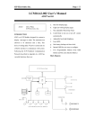
A129 is an 128X64 dots Graphic LCD Module
functions.
Support block save (512KB volatile
designed for system to display messages. The
memory), and block recall functions.
maximum allowed 8 lines and 21 columns
characters to be shown in one screen. The device
Implementation
is easy to install because it uses only a 2-wire
The device consist of two major components:
RS232 Transmit and Receive interface to
a.
One A129 board
b.
One UART Cable
communicate with system, and another 2 wires
for +5V power supply and ground connectivity.
Based
on
ICP
Peripheral
Communication
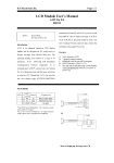
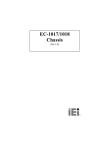
Pin definition
Protocol in Appendix A, A129 also provide two
JP1
readable buttons and one shift encoder roller
switch for system to access external information,
three basic graphic elements like point, line and
rectangle for user easy to construct their own
display
background
and
block
function
1
VCC
Power
(+5V)
5V power in
RS232 Data Input From
PC
RS232 Data Output
3 Tx
Out
From A129
4 GND Power
Ground
2
Rx
In
**The RS232 uses fixed 1200 Baud Rate, 8 bit, 1 stop bit,
no parity check, default ±12V Signal.
Note: If A129 want to be installed on a 5V signal transaction
supported which can save graphic patterns in
memory and be call out to display on the LCD.
(UART), please refer to Appendix B for modification.
ICP Electronics Inc.
Page 2/25
instead of 0x0a like,
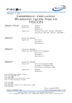
Cable
JP2
+5V
GROUND
_
_
Send to A129: 0x4D 052 0x00 0x48 0x65 0x6c
Power
P1
JP1
1
2
3
4
Transmit from PC to A129
Transmit from A129 to PC
A129
1
6
2
7
3
8
4
9
5
0x6c 0x6f 0x00
(where the last 0x00 illustrate the end of string.)
COM1 or COM2
And Send twice again you will get the display
How to Displaying Messages on LCD
like below, which will immediately follow last
A129 is able to display most of the characters
character of string.
you can find in the ASCII codes. Here is an
HelloHello ←
example to display text messages on the LCD.
Send to A129: 0x4D 052 0x00 0x48 0x65 0x6c
0x6c 0x6f 0x0a
Where:
Certainly, when text fill all the screen and cursor
0x4D
The prefix code.
move to the bottom of screen, then the screen
0x52
Put String on LCD
will rolling up one line for new string to be put.
0x00
Normal Display
0x48 0x65 0x6c 0x6c 0x6f
Another method to display string is like that,
ASCII codes for ‘Hello’
0x0a
New line
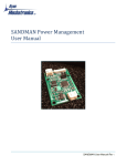
Send to A129 : 0x4D 0x54 0x04 0x05
You can see the text ‘Hello’ is display on the
upper-left corner of LCD like,
Hello
←
Where:
0x4D
The prefix code.
0x54
Cursor Move to
0x04 0x05 Column 4, Row 5
Where the direction of Column and row can be
point like,
And give you a new line below. (Cursor is
un-viewable);
Alternately, if you use the control code 0x00 to
ICP Electronics Inc.
Page 3/25
Column
(0, 0)
(20, 0)
Row
Please reference the Appendix C to see the
content of three code sets that A129 provide and
reference the Select Code Set Command (0x63)
(0, 7)
(20, 7)
Appendix A and select properly code set to be
used.
And then
Example :
Send to A129: 0x4D 052 0x00 0x48 0x65 0x6c
0x6c 0x6f 0x00
Send to A129 : 0x4D 0x63 0x01
Which will select Code Set 1.
Note: A129 is default set to use code set 0 when power on.
Hello ←
How to draw a point, line and rectangle on
LCD
A129 is easy to let you display the basic drawing
elements on the LCD, below is some example
Which will display Hello start on column 4, row
show to you
5.
A. Point
Send to A129 : 0x4D 0x50 0x10 0x20 0x01
Also, if the display mode be changed to 0x01,
the inverse mode, where will inverse the string
Where:
display on the screen. Like,
0x4D
The prefix code.
0x50
Drawing a Point
Send to A129: 0x4D 052 0x01 0x48 0x65 0x6c
0x10, 0x20 On Point (16, 32)
0x01
Display On
0x6c 0x6f 0x0a
Which will draw a point at vector (16, 32). The
Hello
←
last byte 0x01 illustrate the point is turn on and
can be seen a black point on the LCD,
Where the coordinate on the screen can be show
like,
ICP Electronics Inc.
(0, 0)
Page 4/25
(127, 0)
Where:
0x4D
The prefix code.
0x62
Drawing a Rectangle
0x00, 0x00 Start point at (0, 0)
0x7F, 0x3F End point at (127, 63)
(0, 63)
(127, 63)
Alternately if use the 0x00 to instead 0x01
0x01
Display On
How to Turn Off the Back Light of LCD
which like
Sometime, if you feel the back light of LCD is
Send to A129 : 0x4D 0x50 0x10 0x20 0x00
too bright or not necessary, you can turn off it by
this way:
Will turn off or erase the point on (16, 32), a
white point instead the previous one.
Send to A125 : 0x4D 0x5E 0x00
B. Line
Where 0x4D the same and 0x5E is the command
to turn on/off the LCD back light, and 0x00
Send to A129 : 0x4D 0x51 0x00 0x00 0x64 0x64
instruct to turn off.
0x01
Also similarly
Will draw a Line from (0,0) to (100, 100).
Send to A125 : 0x4D 0x5E 0x01
Where:
0x4D
The prefix code.
0x51
Drawing a line.
Will turn on the back light of LCD.
0x00, 0x00 The Start Point of line
0x64, 0x64 The End Point of Line
0x01
Display on
The Same, you can use 0x00 to instead 0x01 to
erase the whole line.
C. Rectangle
Send to A129 : 0x4D 0x62 0x00 0x00 0x7F 0x3F
0x01
Will draw a Rectangular from (0, 0) to (127, 63).
How to store a block and display on the LCD
A129 implement a 512K bytes of Flash ROM
memory which could store approximately about
260,096 display points (where one point will
occupy 2 byte of memory) and which could be
separate into 8 big block set and one big block
set own 256 block maximum, each block will be
assigned a block number from 0 to 255, and will
ICP Electronics Inc.
Page 5/25
share memory maximum 64K bytes, user could
not exceed over 32512 points.
polling the memory are left in by How
Certainly, A129 provide a reserve byte for
Many_Flash
and
custom to program to identify or mark the
estimate the memory will used before to write
writing history of memory, detail please see the
into, else, if A129 find there is not enough
three command of Appendix A
ROM_available
(0x58)
memory during writing A129 will NAK the
writing and delete the contents be written
Write Custom ID : 0x5B
concurrently.
Get Custom ID : 0x5C
Report Custom ID : 0x5D
The estimate method is quite easy, if the block
has 230 black points, where will use up 230 x 2
= 640 bytes memory to store, second polling the
A. Save the block into memory
A129 use
example
Send to A129 : 0x4D 0x58 0x00
Send to A129 : 0x4D 0x55 0x00 0x00 0x00 0x04
0x00 0x08 0x00 0x09 0x01 0x08 0x01 0x09
Where
0x4D
The prefix code.
Where
0x58
How Many Flash ROM are available
0x4D
The prefix code
0x00
Assign Block Set 0 to be questioned
0x55
Save a Block to Flash ROM
0x00
Block Set assign to 0
0x00
Block number assign to 0
And receive the answer from A129
0x00, 0x04 There are four points in this block
Receive from A129 : 0x53 0x59 0x00 0x01 0x00
0x00, 0x08 Point one (0,8)
0x00, 0x09 Point two (0, 9)
Wher:
0x01, 0x08 Point three (1, 8)
0x53
The prefix code
0x59
Report How Many Flash ROM are
available
0x01, 0x09 Point four (1, 9)
Where these four points will relate to a reference
0x00
Block Set 0
point to the left-up corner of this block and
0x01
Hi Byte of pages
which is un-visible but later will be treat as the
0x00
Lo Byte of pages
anchor point by command Display a Block
So, there is 0x0100 = 256 pages=256 x 254
bytes (1 page = 254 bytes) vacuous memory in
block set 0 which could allow you to save about
256 x 254 / 2=32512 points in.
This mean the block is safe to store into the
block set 0 memory if the memory required does
from Flash ROM to LCD ( 0x56)
ICP Electronics Inc.
0
0 1
Page 6/25
reference to Appendix A
Globally Memory Commands
8
9
Reset : 0xFF
Which will clear all block memory and set
custom ID to 0x00.
B. Display a Block from Flash ROM to LCD
Block Set Related Commands
Send to A129 : 0x4D 0x56 0x00 0x00 0x01 0x30
How Many Flash ROM Available : 0x58
0x30
Report How Many Flash ROM Available : 0x59
Get Block Status : 0x68
Will draw block 0 of block set 0 on start point
Report The Block Status : 0x69
(48, 48)
Unit Block Related Commands
Where:
0x4D
The prefix code
Delete a Block from Flash ROM : 0x57
0x56
Display a block from Flash ROM to
Save a Block to Flash ROM : 0x55
Display a Block to LCD : 0x56
LCD
0x00
Block Set 0
0x00
Block Number 0
0x01
Display On
0x30, 0x30 The reference point (or start point, or
anchor point) at (48, 48)
.
(48, 48)
A129 Support totally 8 command to manage the
block memory and could be simply separated
into three groups, more detail description please
ICP Electronics Inc.
Page 7/25
Appendix A
The Graphic LCD A129 Communication Protocol Version 0.2
128x64 dots
Get ID : 0x00
Direction
Content
Command
Emphasis
Response To
Example
Acknowledge
from A129
PC → A129
Get ID
0x4D 0x00
0x4D=Prefix Code; 0x00=Get ID
None
0x4D 0x00
0x53 0x01 0x00 0x81
Report ID : 0x01
Direction
A129 → PC
Content
Report ID
Command
0x53 0x01 0xXX 0xYY
Emphasis
0x53=Prefix code; 0x01=Report ID; 0xXXYY=ID;
Response To
Get ID
Example
0x53 0x01 0x00 0x81 (Board ID=0x0081=129)
Acknowledge
None
from PC
Set LED On/Off : 0x02
Direction
PC → A129
Content
Set LED On/Off
Command
0x4D 0x02 0xXX 0xYY
Emphasis
0x4D=Prefix; 0x02=Set LED On/Off; 0xXXYY=LED on/off,
XXYY<15:0>=LED<15:0>, 1=On, 0=off
Response To
None
Example
0x4D 0x02 0x00 0x03 (Set LED0, LED1 On)
Acknowledge
None
from A129
Get LED Status : 0x03
Direction
PC → A129
Content
Get LED Status
Command
0x4D 0x03
Emphasis
0x4D=Prefix code; 0x03=Get LED Status
Response To
None
Example
0x4D 0x03
Acknowledge
0x53 0x04 0x00 0x03 (Report LED Status now LED0, LED1 is On)
from A129
ICP Electronics Inc.
Page 8/25
Report LED Status : 0x04
Direction
A129 → PC
Content
Report LED Status
Command
0x53 0x04 0xXX 0xYY
Emphasis
0x53=Prefix Code; 0x04=Report LED status; 0xXXYY=LED on/off
XXYY<15:0>=LED<15:0>, 1=On, 0=Off
Response To
Get LED Status 0x03
Example
0x53 0x04 0x00 0x0F (LED<3:0> is On)
Acknowledge
None
from PC
Report Switches Status : 0x05
Direction
A129 → PC
Content
Report Switches Status
Command
0x53 0x05 0xXX 0xYY
Emphasis
0x53=Prefix code; 0x05=Report Switches status; 0xXXYY=Switches on/off
XXYY<15:0>=Switch<15:0>, 1=Pressed, 0=Release
Response To
Example
Acknowledge
from PC
Note:
This command will automatic report when the switch is pressed
The Shift Encoder rotate CW/CCW one step will be treat like switch 0 or 1 be
pressed once and release.
Auto Report or Receive Get Switches Status Command 0x06
0x53 0x05 0x00 0x01 (Sw0 is On)
None
Get Switches Status : 0x06
Direction
PC → A129
Content
Get Switches Status
Command
0x4D 0x06
Emphasis
0x4D=Prefix Code; 0x06=Get Switches status
Response To
None
Example
0x4D 0x06
Acknowledge
0x53 0x05 0x00 0x01 (Report Switch Status Sw0 is On).
from A129
Get Protocol version : 0x07
Direction
PC → A129
Content
Get Protocol version
Command
0x4D 0x07
Emphasis
0x4D=Prefix code; 0x07=Get Protocol version
Response To
None
Example
0x4D 0x07
Acknowledge
0x53 0x08 0x 00 0x02 (Report Protocol version is 0.2)
from A129
Report Protocol Version : 0x08
Direction
A129 → PC
Content
Report Protocol version
Command
0x53 0x08 0xXX 0xYY
ICP Electronics Inc.
Emphasis
Response To
Example
Acknowledge
from PC
Page 9/25
0x53=Prefix code; 0x08=Report Protocol version; 0xXX=Class(0x00 ~ 0xFF);
0xYY=version (00~FF);
Get Protocol Version 0x07
0x53 0x08 0x00 0x02 (Version 0.2)
None
Display Character On : 0x0C
Direction
Content
Command
Emphasis
Response To
Example
Acknowledge
from A129
PC → A129
Display Character on LCD
0x4D 0x0C 0x0L 0x0N 0xCC1 ~ 0xCC15
0x4D=Prefix Code; 0x0C=Display Character On LCD; 0x0L=0x00 (Line 0) ~
0x07(Line 7); 0x0N=N Character (1~21), no more than 21 characters; 0xCCn=Code
of Characters, Pls Reference Appendix C Code Set Table.
None
0x4D 0x0C 0x01 0x03 0x49 0x43 0x50 (Line 1, 3 Characters, ‘ICP’)
None
Clear LCD : 0x0D
Direction
PC → A129
Content
Clear LCD
Command
0x4D 0x0D
Emphasis
0x4D=Prefix code; 0x0D=Clear LCD
Response To
None
Example
0x4D 0x0D
Acknowledge
None
from A129
Point : 0x50
Direction
Content
Command
Emphasis
Response To
Example
Acknowledge
from A129
PC → A129
Draw a Point on X, Y
0x4D 0x50 0xXX 0xYY 0xDD
0x4D=Prefix Code; 0x50=Draw a Point Command, 0xXX=X coordinate (0x00 to
0x7F), 0xYY=Y Coordinate (0x00 t0 0x3F), 0xDD=Display On/Off (0x01=Display
On (draw), 0x00=Display Off (erase)).
None
0x4D 0x50 0x10 0x20 0x01 (will draw a point at vector (16, 32)).
None
Line : 0x51
Direction
Content
Command
Emphasis
Response To
PC → A129
Draw a Line from (X1, Y1) to (X2, Y2)
0x4D 0x51 0xXX1 0xYY1 0xXX2 0xYY2 0xDD
0x4D=Prefix code; 0x51=Draw a Line Command; 0xXX1=X1 Coordinate (0x00 to
0x7F), 0xYY1=Y1 Coordinate (0x00 to 0x3F), 0xXX2=X2 Coordinate (0x00 to
0x7F), 0xYY2=Y2 Coordinate (0x00 to 0x3F), 0xDD= Display On/Off
(0x01=Display On (draw), 0x00=Display Off (erase)).
None
ICP Electronics Inc.
Example
Acknowledge
from A129
Page 10/25
0x4D 0x51 0x00 0x00 0x64 0x64 0x01 (Draw a Line from (0,0) to (100, 100)).
0x4D 0x51 0x00 0x00 0x64 0x64 0x00 (Erase a Line from (0,0) to (100, 100)).
None
Put String : 0x52
Direction
Content
Command
Emphasis
Response To
Example
Acknowledge
from A129
PC → A129
Put a string on LCD, if at the bottom line then scrolling the text windows up. String
terminate by 0x00 (end of string) or 0x0a (new line).
0x4D 0x52 0xMM 0xCC1 0xCC2 ……… 0xDD
0x4D=M; 0x52=Put String Command; 0xCC1 0xCC2 ……… Display characters,
0xMM=mode of Character, 0x00=Normal Display, 0x01=Inverse Display;
0xDD=Control character where 0xDD=0x00=End of String, or 0xDD=0x0a=End of
String and add feed line and carriage return.
None
0x4D 0x52 0x00 0x48 0x65 0x6c 0x6c 0x6f 0x0a (put a string “Hello” on LCD)
0x4D 0x52 0x01 0x48 0x65 0x6c 0x6c 0x6f 0x0a (put a string “Hello” on LCD but
inverse)
None
Cursor goto : 0x54
Direction
Content
Command
Emphasis
Response To
Example
Acknowledge
from A129
PC → A129
Move Cursor to Text Position M, N (one character is a 8x6 dots square)
0x4D 0x54 0xMM 0xNN
0x4D=Prefix code; 0x54=Cursor Goto Command, 0xMM=Horizon Position relate to
Left corner (0x00 to 0x14), 0xNN=Vertical Position relate to Upper corner (0x00 to
0x07)
Note : The text window only have 21 column width and 8 rows.
None
0x4D 0x54 0x04 0x05 (Cursor move to Column 4, Row 5)
None
Save a Block to Flash ROM : 0x55
Direction
Content
Command
Emphasis
Response To
Example
Acknowledge
PC → A129
Save a Block to Flash ROM
0x4D 0x55 0xMM 0xNN 0xPP_hi 0xPP_lo 0xXX1 0xYY1 0xXX2 0xYY2 ………..
0x4D=Prefix code; 0x55=Save a Block, 0xMM=Block Set (0x00 to 0x07),
0xNN=Block Number (0x00 to 0xFF), 0xPP_hi, 0xPP_lo=Points in Block (0x0001
to 0xFE00), 0xXX1= X Coordinate of Point 1 (0x00 to 0x7F), 0xYY1= Y Coordinate
of Point 1 (0x00 to 0x3F), 0xXX2= X Coordinate of Point 2 (0x00 to 0x7F), 0xYY2=
Y Coordinate of Point 2 (0x00 to 0x3F), ……Coordinate relate to left, upper corner
of block.
Note : if the Block Set Over 0x07 or there are no valid memory to save, LCD will
response a NAK to this command.
None
0x4D 0x55 0x01 0x00 0x00 0x04 0x00 0x08 0x00 0x09 0x01 0x08 0x01 0x09
(Save a Block to Flash ROM, Block Set=0x01, Block Number= 0x00, Total 4 points,
point are (0, 8), (0, 9), (1, 8), (1, 9).
0xFA
ICP Electronics Inc.
Page 11/25
from A129
Display a Block from Flash ROM to LCD : 0x56
Direction
Content
Command
Emphasis
Response To
Example
Acknowledge
from A129
PC → A129
Display the Block from Flash ROM to LCD at Start Point (X, Y)
0x4D 0x56 0xMM 0xNN 0xDD 0xXX 0xYY
0x4D=Prefix code; 0x56=Display the Block to LCD, 0xMM=The Block Set (0x00 to
0x07), 0xNN=Block Number (0x00 to 0xFF), 0xDD=Display On/Off, 0x01=Display
On (Draw), 0x00=Display Off (Erase), 0xXX1=Start at Point X1 Coordinate (0x00 to
0x7F) and, 0xYY1=Start at Y1 Coordinate (0x00 to 0x3F) relate to the left-upper
corner of block.
None
0x4D 0x56 0x00 0x00 0x01 0x30 0x30 (Display the (Block Set, Block Num)=(0x00,
0x00) at (48, 48)) Display Mode=On.).
None
Delete a Block in the Flash ROM
Direction
Content
Command
Emphasis
Response To
Example
Acknowledge
from A129
: 0x57
PC → A129
Delete the Block which has saved in Flash Rom
0x4D 0x57 0xMM 0xNN
0x4D=Prefix code; 0x57=Delete a Block, 0xMM=The Block Set (0x00 to 0x07),
0xNN=Block Number (0x00 to 0xFF).
None
0x4D 0x57 0x00 0x00 (Delete the Block Num 0 in Block Set 0)
0xFA
How many Flash ROM are available in the Block Set : 0x58
Direction
Content
Command
Emphasis
Response To
Example
Acknowledge
from A129
PC → A129
Ask How many Flash ROM are available in the Block Set
0x4D 0x58 0xMM
0x4D=Prefix code; 0x58=Ask how many Flash ROM available; 0xMM=The Block
Set (From 0x00 to 0x07);
Note : A129 will response number of pages that available in memory, one page equal
to 254 bytes which could use to save 127 points of data.
None
0x4D 0x58 0x07 (Ask How Many Memory Available in Block Set 7)
0x53 0x59 0x07 0x01 0x00 (Report How many Flash ROM are Available in Block
Set 7, 0x0100 = 256 pages = 256 x 254 bytes = 65024 bytes = 32512 points free)
Report how many Flash ROM available : 0x59
Direction
Content
Command
Emphasis
Response To
Example
Acknowledge
A129 → PC
Report how many Flash ROM are available
0x53 0x59 0xMM 0xAA 0xBB
0x53=Prefix code; 0x59=Report how many Flash ROM are available, 0xMM=The
Block Set to be Report; 0xAABB= pages are available in Flash ROM, 1 page=254
bytes
How many Flash ROM are available (0x58)
0x53 0x59 0x00 0x00 0xFE (There are 254 pages (64516 bytes) available in Flash
ROM in Block Set 0);
None
ICP Electronics Inc.
Page 12/25
from PC
Write Custom ID : 0x5B
Direction
Content
Command
Emphasis
Response To
Example
Acknowledge
from A129
PC → A129
Write Custom ID to EEPROM
0x4D 0x5B 0xID
0x4D=Prefix code; 0x5B=Write Custom ID to EEPROM, 0xID=Custom ID (0x00 to
0xFF), Custom ID is a free and special reserved byte for custom to make a mark on
block ID memory. Custom could use this byte to identify the history of programming
of block memory.
None
0x4D 0x5B 0xAA (Put a mark 0xAA into block ID memory)
None
Get Custom ID : 0x5C
Direction
Content
Command
Emphasis
Response To
Example
Acknowledge
from a129
PC → A129
Get Custom ID
0x4D 0x5C
0x4D=Prefix code; 0x5C=Get Custom ID.
None
0x4D 0x5C
0x53 0x5D 0xAA (Report Custom ID = 0xAA)
Report Custom ID : 0x5D
Direction
Content
Command
Emphasis
Response To
Example
Acknowledge
from PC
A129 → PC
Report Custom ID
0x53 0x5D 0xID
0x53=Prefix code; 0x5D=Report Custom ID; 0xID=Custom ID which has been
writen by Write_Custom_ID Command
Get Custom ID 0x5C
0x53 0x5D 0xAA (Custom ID is 0xAA)
None
Set Back Light On/Off : 0x5E
Direction
Content
Command
Emphasis
Response To
Example
Acknowledge
PC → A129
Set Back Light On/Off
0x4D 0x5E 0x0X
0x4D=Prefix code; 0x5E=Set Back Light On/Off, 0x0X=0x00 Back Light off, =0x01
Back Light On
None
0x4D 0x5E 0x01 ( Back Light On)
None
ICP Electronics Inc.
Page 13/25
from A129
Rectangular : 0x62
Direction
Content
Command
Emphasis
Response To
Example
Acknowledge
from A129
PC → A129
Draw a Rectangular start left-upper corner at (X1, Y1) , and stop at right-bottom
corner at (X2, Y2).
0x4D 0x62 0xXX1 0xXY1 0xXX2 0xXY2 0xDD
0x4D=Prefix code; 0x62=Draw a Rectangular Command; 0xXX1=left-upper X
Coordinate (0x00 to 0x7F), 0xYY1=left-upper Y Coordinate (0x00 to 0x3F),
0xXX2=right-bottom X Coordinate (0x00 to 0x7F), 0xYY2=right-bottom Y
Coordinate (0x00 to 0x3F), 0xDD= Display On/Off (0x01=Display On (draw),
0x00=Display Off (erase)).
None
0x4D 0x62 0x00 0x00 0x7F 0x3F 0x01 (Draw a Rectangular from (0, 0) to (127,
63)).
0x4D 0x62 0x10 0x20 0x15 0x25 0x00 (Erase a Rectangular from (16, 32) to (21,
37)).
None
Select Code Set : 0x63
Direction
PC → A129
Content
Select Code Set
Command
0x4D 0x63 0xXX
Emphasis
0x4D=Prefix code; 0x63=Select Code Set; 0xXX=Code Set Number from 0 to 2.
Response To
None
Example
0x4D 0x63 0x01 ( Select Code Set 1, about the content of code set, please see
Appendix C.)
Acknowledge
None
from A129
Get Code Set : 0x64
Direction
PC → A129
Content
Get Code Set Number now be set
Command
0x4D 0x64
Emphasis
0x4D=Prefix code; 0x64=Get Code Set Number
Response To
None
Example
0x4D 0x64
Acknowledge
0x53 0x65 0x01 (Report Code Set Number Now be Set on Code Set 1)
from a129
Report Code Set : 0x65
Direction
A129 → PC
Content
Report The Code Set Number Now be Set
Command
0x53 0x65 0xXX
Emphasis
0x53=Prefix code; 0x65=Report The Code Set Now be Set; 0xXX=The Code Set
Now Be Set.
Response To
Get Code Set 0x64
Example
0x53 0x65 0x01 (Report Code Set Number Now be Set on Code Set 1)
Acknowledge
None
from PC
ICP Electronics Inc.
Page 14/25
Get Block Set Status : 0x68
Direction
PC → A129
Content
Get Block Set Status, Get How many blocks are exist in the block set x, and what is
the block number be used.
Command
0x4D 0x68 0xMM
Emphasis
0x4D=Prefix code; 0x68=Get Block Set Status; 0xMM=Block Set (0x00 to 0x07);
Response To
None
Example
0x4D 0x68 0x00 (Get Block Set 0 Status)
Acknowledge
0x53 0x69 0x00 0x00 0x08 0x00 0x01 0x02 0x03 0x04 0x05 0x06 0x07 (Report
from A129
Block Set 0 Status, there are 8 block exist in block set 0, block number are 0, 1, 2, 3,
4, 5, 6, 7)
Report Block Set Status : 0x69
Direction
A129 → PC
Content
Report The Block Set Status
Command
0x53 0x69 0xMM 0xAA 0xBB 0xNN0 0xNN1 0xNN2……
Emphasis
0x53=Prefix code; 0x69=Report The Block Set Status; 0xMM=The Block Set to be
Report; 0xAABB=The Number of Block exist in the Block Set 0xMM; 0xNNx=The
Block Number exist (has been registered) in this Block Set.
Response To
Get Block Status 0x68
Example
0x53 0x69 0x00 0x00 0x04 0x00 0x01 0x07 0x08 (There are 4 block in Block Set 0
which are Block Number 0, Block Number 1, Block Number 7 and Block Number 8)
Acknowledge
None
from PC
Ack : 0xFA
Direction
Content
Command
Emphasis
Response To
Example
Acknowledge
from PC
A129 → PC
Simple Ack
0xFA
0xFA=Ack;
Save a Block to Flash ROM 0x55, Delete a Block in the Flash ROM 0x57
0xFA
None
Nack : 0xFB
Direction
Content
Command
Emphasis
Response To
Example
Acknowledge
from PC
A129 → PC
Negative Ack
0x53 0xFB 0xCC
0x53=Prefix code; 0xFB=Negative Ack; 0xCC Command;
Ack No Support this command 0xCC
0x53 0xFB 0xF0 (NAK 0xF0 Command)
None
Reset : 0xFF
ICP Electronics Inc.
Direction
Content
Command
Emphasis
Response To
Example
Acknowledge
from A129
Page 15/25
PC → A129
Reset, this command will clear all contents in block memory and set custom ID to
0x00. This command will take about 60 sec to finish.
0x4D 0xFF
0x4D=Prefix code; 0xFF=Reset Command
None
0x4D 0xFF
0x53 0xAA
Reset OK : 0xAA
Direction
A129 → PC
Content
Reset OK
Command
0x53 0xAA
Emphasis
0x53=Prefix code; 0xAA=Reset OK;
Response To
Reset 0xFF
Example
0x53 0xAA
Acknowledge
None
from PC
ICP Electronics Inc.
Page 16/25
Appendix B
Modifying A129 to UART (+5V Signal) or RS232 (±12V Signal)
The internal signal from the micro processor of A129 is UART 5V. To switch between UART +5V and
RS232 ±12V signal interfaces, please refer to the table below.
Components
UART
RS232
U2
N/A
RS232 Transceiver like
LT1381CS
C1, 2, 3, 4, 5
N/A
0.1uF
R5, 6
0 ohm or jumper
N/A
ICP Electronics Inc.
Page 17/25
Appendix C
LCD-Module-supported ASCII codes and Symbol codes
Code Set 0 :
LF
0x00
0x01
0x02
0x03
0x04
0x05
0x06
0x07
0x08
0x09
0x0A
0x0B
0x0C
LF/CR
.
0x0D 0x0E
/
0x0F
&
0x10
*
0x11
﹫
0x12
`
0x13
̃
0x14
△
0x15
10
0x16
12
0x17
15
0x18
ℓ
0x19
0x1A
χ
0x1B
0x1C
Ⅰ
0x1D
Ⅱ
0x1E
◄
0x1F
0x20
!
0x21
“
0x22
#
0x23
$
0x24
%
0x25
&
0x26
‘
0x27
(
0x28
)
0x29
*
0x2A
+
0x2B
,
0x2C
0x2D
.
0x2E
/
0x2F
0
0x30
1
0x31
2
0x32
3
0x33
4
0x34
5
0x35
6
0x36
7
0x37
8
0x38
9
0x39
:
0x3A
;
0x3B
<
0x3C
=
0x3D
>
0x3E
?
0x3F
@
0x40
A
0x41
B
0x42
C
0x43
D
0x44
E
0x45
F
0x46
G
0x47
H
0x48
I
0x49
J
0x4A
K
0x4B
L
0x4C
M
0x4D
N
0x4E
O
0x4F
P
0x50
Q
0x51
R
0x52
S
0x53
T
0x54
U
0x55
V
0x56
W
0x57
X
0x58
Y
0x59
Z
0x5A
[
0x5B
¥
0x5C
]
0x5D
^
0x5E
_
0x5F
`
0x60
a
0x61
b
0x62
c
0x63
d
0x64
e
0x65
f
0x66
g
0x67
h
0x68
i
0x69
j
0x6A
k
0x6B
l
0x6C
m
0x6D
n
0x6E
o
0x6F
p
0x70
q
0x71
r
0x72
s
0x73
t
0x74
u
0x75
v
0x76
w
0x77
x
0x78
y
0x79
z
0x7A
{
0x7B
|
0x7C
}
0x7D
→
0x7E
←
0x7F
►
0x80
0x81
0x82
▪
0x83
Д
0x84
Ц
0x85
Щ
0x86
д
0x87
ф
0x88
ц
0x89
щ
0x8A
ç
0x8B
♠
0x8C
○
0x8D
○
0x8E
¼
0x8F
⅓
0x90
½
0x91
¾
0x92
0x93
0x94
0x95
0x96
0x97
0x98
0x99
0x9A
0x9B
§
0x9C
¶
0x9D
0x9E
0x9F
0xA0
。
0xA1
「
0xA2
」
0xA3
ˋ
0xA4
•
0xA5
ヲ
0xA6
ァ
0xA7
ィ
0xA8
ゥ
ェ
ォ
ャ
ュ
ョ
ッ
0xA9 0xAA 0xAB 0xAC 0xAD 0xAE 0xAF
ー
0xB0
ア
0xB1
イ
0xB2
ウ
0xB3
エ
0xB4
オ
0xB5
カ
0xB6
キ
0xB7
ク
0xB8
ケ
コ
サ
シ
ス
セ
0xB9 0xBA 0xBB 0xBC 0xBD 0xBE
ソ
0xBF
タ
0xC0
チ
0xC1
ツ
0xC2
テ
0xC3
ト
0xC4
ナ
0xC5
ニ
0xC6
ヌ
0xC7
ネ
0xC8
ノ
ハ
ヒ
フ
ヘ
ホ
0xC9 0xCA 0xCB 0xCC 0xCD 0xCE
マ
0xCF
ミ
0xD0
ム
0xD1
メ
0xD2
モ
0xD3
ヤ
0xD4
ユ
0xD5
ヨ
0xD6
ラ
0xD7
リ
0xD8
ル
レ
ロ
ワ
ン
゙
゚
0xD9 0xDA 0xDB 0xDC 0xDD 0xDE 0xDF
ICP Electronics Inc.
Page 18/25
α
0xE0
ä
0xE1
β
0xE2
ε
0xE3
μ
0xE4
σ
0xE5
ρ
0xE6
q
0xE7
√
0xE8
-1
0xE9
×
¢
ñ
¡
₤
0xEA 0xEB 0xEC 0xED 0xEE
ö
0xEF
p
0xF0
q
0xF1
θ
0xF2
∞
0xF3
Ω
0xF4
ü
0xF5
Σ
0xF6
π
0xF7
0xF8
ц
0xF9
チ
0xFA
万
0xFB
丹
0xFC
÷
0xFD
0xFE
▊
0xFF
Code Set 1
LF
0x00
0x01
0x02
0x03
0x04
0x05
0x06
0x07
0x08
0x09
0x0A
0x0B
0x0C
CR/LF
0x0D 0x0E
0x0F
Ĕ
0x10
Æ
0x11
Æ
0x12
ô
0x13
ö
0x14
ò
0x15
û
0x16
ù
0x17
ÿ
0x18
Ö
0x19
Ü
0x1A
ň
0x1B
Ň
0x1C
ª
0x1D
o
0x1E
¿
0x1F
á
0x20
Í
0x21
ó
0x22
ú
0x23
¢
0x24
£
0x25
¥
0x26
₧
0x27
ƒ‘
0x28
¡
0x29
Ã
0x2A
ã
0x2B
Õ
0x2C
õ
0x2D
Ø
0x2E
ψ
0x2F
•
0x30
‥
0x31
°
0x32
‵
0x33
′
0x34
½
0x35
¼
0x36
╳
0x37
÷
0x38
﹤
0x39
﹥
0x3A
«
0x3B
»
0x3C
≠
0x3D
√
0x3E
̅
0x3F
⌠
0x40
⌡
0x41
∞
0x42
▽
0x43
↙
0x44
↑
0x45
↓
0x46
→
0x47
←
0x48
╒
0x49
╕
0x4A
└
0x4B
┘
0x4C
。
0x4D
®
0x4E
©
0x4F
™
0x50
┼
0x51
§
0x52
¶
0x53
Γ
0x54
⊿
0x55
Θ
0x56
Λ
0x57
Ξ
0x58
Π
0x59
Σ
0x5A
Υ
0x5B
Φ
0x5C
Ψ
0x5D
Ω
0x5E
α
0x5F
β
0x60
γ
0x61
δ
0x62
ε
0x63
ζ
0x64
η
0x65
θ
0x66
ι
0x67
κ
0x68
λ
0x69
μ
0x6A
ν
0x6B
ξ
0x6C
π
0x6D
ρ
0x6E
σ
0x6F
τ
0x70
υ
0x71
χ
0x72
ψ
0x73
ω
0x74
▼
0x75
►
0x76
◄
0x77
R
0x78
←|
0x79
F
0x7A
→|
0x7B
□
0x7C
═
0x7D
S
0x7E
P
0x7F
Û
0x80
Ù
0x81
Ú
0x82
Ü
0x83
û
0x84
ù
0x85
ú
0x86
Ô
0x87
Ò
0x88
Ó
0x89
º
0x8A
ô
0x8B
ò
0x8C
ó
0x8D
ö
0x8E
Ê
0x8F
È
0x90
É
0x91
Ë
0x92
ê
0x93
è
0x94
é
0x95
ë
0x96
Å
0x97
Ä
0x98
å
0x99
â
0x9A
à
0x9B
á
0x9C
ä
0x9D
A
0x9E
ª
0x9F
î
0xA0
ì
0xA1
í
0xA2
ï
0xA3
¡
0xA4
Ñ
0xA5
ñ
0xA6
N’
0xA7
g
0xA8
g
v
v
w
m
Æ
§
0xA9 0xAA 0xAB 0xAC 0xAD 0xAE 0xAF
ij
0xB0
ƒ
0xB1
£
0xB2
→|
0xB3
↓
0xB4
↑
0xB5
↓
0xB6
¶
0xB7
½
0xB8
⅓
ø
Ŀ
Ð
ß
¼
0xB9 0xBA 0xBB 0xBC 0xBD 0xBE
Ç
0xBF
₢
0xC0
¤
0xC1
□
0xC2
µ
0xC3
ø
0xC4
ÿ
0xC5
Ã
0xC6
¢
0xC7
ã
0xC8
T
Õ
õ
̃
ŀ
≡
0xC9 0xCA 0xCB 0xCC 0xCD 0xCE
Б
0xCF
Γ
0xD0
Ë
0xD1
Ж
0xD2
З
0xD3
И
0xD4
Й
0xD5
Л
0xD6
П
0xD7
У
0xD8
Ф
Ч
Ш
Ъ
Ы
Э
Ю
0xD9 0xDA 0xDB 0xDC 0xDD 0xDE 0xDF
ICP Electronics Inc.
Page 19/25
Я
0xE0
б
0xE1
в
0xE2
г
0xE3
ж
0xE4
з
0xE5
иf
0xE6
й
0xE7
к
0xE8
л
0xE9
м
н
п
т
у
0xEA 0xEB 0xEC 0xED 0xEE
ш
0xEF
ъ
0xF0
ы
0xF1
ь
0xF2
э
0xF3
ю
0xF4
я
0xF5
«
0xF6
»
0xF7
“
0xF8
”
0xF9
№
0xFA
£
0xFB
¸
0xFC
0xFD
0xFE
‼
0xFF
Code Set 2
LF
0x00
0x01
0x02
0x03
0x04
0x05
0x06
0x07
0x08
0x09
0x0A
0x0B
0x0C
LF/CR
.
0x0D 0x0E
/
0x0F
±
0x00
≡
0x01
∑
0x02
∑
0x03
╭
0x04
╰
0x05
╮
0x06
╯
0x07
{
0x08
}
0x09
≈
0x0A
∫
0x0B
=
0x0C
~
0x0D
²
0x0E
³
0x0F
Ç
0x10
ü
0x11
é
0x12
â
0x13
ä
0x14
à
0x15
a
0x16
ç
0x17
ê
0x18
ë
0x19
è
0x1A
ï
0x1B
î
0x1C
ì
0x1D
Ä
0x1E
Â
0x1F
ICP Electronics Inc.
Page 20/25
Appendix D
Demo Program 1
/*
*
*
Title
: A129 Demo program
*
Editor
: Davis Wang in ICP Electronic
*
Compilier : TC 2.0
*
OS
*
Execute
: DOS 6.22 or Above
: C:\print String
*
where String will display on LCD
*
*
e.g. C:\print ICP_Electronic
*
*/
#include <dos.h>
#include <stdio.h>
#include <conio.h>
#define COM1
0x3f8
#define COM2
0x2f8
#define IOBASE COM1
void InitUART(void){
outport(IOBASE+3, 0x80);
/* Line Control Register */
outport(IOBASE+0, 0x60);
/* Divisor Latch Low
outport(IOBASE+1, 0x00);
/* Divisor Latch High
outport(IOBASE+3, 0x03);
}
void SendByte(char ch){
*/
*/
ICP Electronics Inc.
while(!(inport(IOBASE+5) & 0x20));
outport(IOBASE, ch);
}
unsigned char GetByte(void){
while(!(inport(IOBASE+5) & 0x01));
return inport(IOBASE);
}
void SendString(char *s){
int i,j;
i=strlen(s);
SendByte(0x4D);
/* prefix code */
SendByte(0x52);
/* put string */
SendByte(0x00);
/* normal mode */
for(j=0; j<i; j++)SendByte(*(s+j));
SendByte(0x0a);
/* Line Feed */
}
void main(int argc, char *argv[]){
InitUART();
SendString(argv[1]);
}
Demo Program 2
/*
*
*
Title
: A129 Demo program
*
Editor
: Davis Wang in ICP Electronic
*
Compilier : TC 2.0
Page 21/25
ICP Electronics Inc.
*
OS
*
Execute
Page 22/25
: DOS 6.22 or Above
: C:\rect x1 y1 x1 y2
*
Draw a rectangle on LCD
*
where (x1, y1) is left up corner, and (x2, y2)
*
is the right bottom corner
*
*
e.g. C:\rect 0 0 120 30
*
*/
#include <dos.h>
#include <stdio.h>
#include <conio.h>
#define COM1
0x3f8
#define COM2
0x2f8
#define IOBASE COM1
void InitUART(void){
outport(IOBASE+3, 0x80);
/* Line Control Register */
outport(IOBASE+0, 0x60);
/* Divisor Latch Low
outport(IOBASE+1, 0x00);
/* Divisor Latch High
outport(IOBASE+3, 0x03);
}
void SendByte(char ch){
while(!(inport(IOBASE+5) & 0x20));
outport(IOBASE, ch);
}
unsigned char GetByte(void){
while(!(inport(IOBASE+5) & 0x01));
return inport(IOBASE);
}
*/
*/
ICP Electronics Inc.
void DrawRect(unsigned char x1, unsigned char y1,
unsigned char x2, unsigned char y2){
SendByte(0x4D);
SendByte(0x62);
SendByte(x1);
SendByte(y1);
SendByte(x2);
SendByte(y2);
SendByte(0x01); /* Display On */
}
void main(int argc, char *argv[]){
InitUART();
DrawRect(atoi(argv[1]), atoi(argv[2]), atoi(argv[3]), atoi(argv[4]));
}
Demo Program 3
/*
*
*
Title
: A129 Demo program
*
Editor
: Davis Wang in ICP Electronic
*
Compilier : TC 2.0
*
OS
*
Execute
*
: DOS 6.22 or Above
: C:\getsts x
getsts will be polling the block status of A129
*
where x is the interest block set of
*
e.g. C:\getsts 0
*
which will polling Block Set 0
*
*/
Page 23/25
ICP Electronics Inc.
Page 24/25
#include <dos.h>
#include <stdio.h>
#include <conio.h>
#define COM1
0x3f8
#define COM2
0x2f8
#define IOBASE COM1
void InitUART(void){
outport(IOBASE+3, 0x80);
/* Line Control Register */
outport(IOBASE+0, 0x60);
/* Divisor Latch Low
outport(IOBASE+1, 0x00);
/* Divisor Latch High
outport(IOBASE+3, 0x03);
}
void SendByte(char ch){
while(!(inport(IOBASE+5) & 0x20));
outport(IOBASE, ch);
}
unsigned char GetByte(void){
while(!(inport(IOBASE+5) & 0x01));
return inport(IOBASE);
}
unsigned char Rs232Avail(void){
return inport(IOBASE+5) & 0x01;
}
void main(int argc, char *argv[]){
unsigned int i,j;
unsigned int blocks;
*/
*/
ICP Electronics Inc.
InitUART();
while(Rs232Avail())GetByte(); /* Clear the Rs232 Recv Buffer */
SendByte(0x4D); /* the prefix code */
SendByte(0x68); /* the Get Block Status command */
SendByte(atoi(argv[1])); /* polling Block Set */
GetByte();
/* skip prefix code 0x53 */
GetByte();
/* skip Report block status command 0x69 */
blocks=GetByte();
i=GetByte();
i=i*256+GetByte();
printf("There are : %4d blocks in block set %4d, it is : \n", i, blocks);
for(j=0;j<i;j++){
printf("%4d", GetByte());
}
}
Page 25/25