1
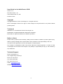
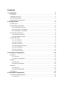
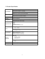
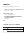
HelloDevice Lite Series LS100 User Guide Version 1.4.4 2011-12-12 1 User Guide for the HelloDevice LS100 Version 1.4.4 Firmware version 1.4.X Last revised on Dec 12, 2011 Printed in Korea Copyright Copyright 2002-2012, Sena Technologies, Inc. All rights reserved. Sena Technologies reserves the right to make changes and improvements to its product without providing notice. Trademark HelloDevice™ is a trademark of Sena Technologies, Inc. Windows® is a registered trademark of Microsoft Corporation. Ethernet® is a registered trademark of XEROX Corporation. Notice to Users Proper back-up systems and necessary safety devices should be utilized to protect against injury, death or property damage due to system failure. Such protection is the responsibility of the user. This device is not approved for use as a life-support or medical system. Any changes or modifications made to this device without the explicit approval or consent of Sena Technologies will void Sena Technologies of any liability or responsibility of injury or loss caused by any malfunction. Technical Support Sena Technologies, Inc. 210 Yangjae-dong, Seocho-gu Seoul 137-130, Korea Tel: (+82-2) 576-7362 Fax: (+82-2) 573-7710 E-Mail: [email protected] Website: http://www.sena.com 2 Contents 1: Introduction 5 1.1 Overview ..................................................................................................................................... 5 1.2 Package Check List .................................................................................................................... 5 1.3 Product Specification................................................................................................................... 6 1.4 Terminologies And Acronyms ...................................................................................................... 7 2: Getting Started 9 2.1 Panel Layout ............................................................................................................................... 9 2.2 Connecting The Hardware ........................................................................................................ 10 2.2.1 Connecting The Power ................................................................................................... 10 2.2.2 Connecting To The Network ........................................................................................... 11 2.2.3 Connecting To The Device ............................................................................................. 12 2.3. Accessing Console Port ........................................................................................................... 12 2.3.1 Using Serial Console ...................................................................................................... 13 2.3.2 Using Remote Console ................................................................................................... 14 2.4 Command Usage ...................................................................................................................... 15 2.4.1 ‘set’ Command ................................................................................................................ 16 2.4.2 ‘get’ Command ................................................................................................................ 17 2.4.3 ‘help’ Command .............................................................................................................. 19 2.4.4 ‘factorydefault’ Command ............................................................................................... 20 2.4.5 ‘save’ Command ............................................................................................................. 20 2.4.6 ‘exit’ Command ............................................................................................................... 20 2.4.7 ‘reboot’ Command........................................................................................................... 21 3: IP Address Configuration 22 3.1 Static IP ..................................................................................................................................... 23 3.1.1 Overview ......................................................................................................................... 23 3.1.2 Static IP Configuration .................................................................................................... 23 3.2 DHCP ........................................................................................................................................ 24 3.2.1 Overview ......................................................................................................................... 24 3.2.2 DHCP Configuration ....................................................................................................... 25 3.3 PPPoE....................................................................................................................................... 25 3.3.1 Overview ......................................................................................................................... 25 3.3.2 PPPoE Configuration ...................................................................................................... 25 3.4 IP Filtering ................................................................................................................................. 26 4: Host Mode Configuration 27 4.1 TCP Server Mode Operations ................................................................................................... 29 4.1.1 Overview ......................................................................................................................... 29 3 4.1.2 TCP Server Mode Configuration ..................................................................................... 31 4.2 TCP Client Mode Operations .................................................................................................... 32 4.2.1 Overview ......................................................................................................................... 32 4.2.2 TCP Client Mode Configuration ...................................................................................... 34 4.3 TCP Server/Client Mode Operations......................................................................................... 34 4.3.1 Overview ......................................................................................................................... 34 4.3.2 TCP Server/Client Mode Configuration........................................................................... 36 5: Serial Port Configuration 6: System Administration Appendix A: Connections 37 40 41 A.1 Ethernet Pinouts ....................................................................................................................... 41 A.2 Serial Port Pinouts .................................................................................................................... 41 A.3 Ethernet Wiring Diagram .......................................................................................................... 42 A.4 Serial Wiring Diagram ............................................................................................................... 42 Appendix B: Well-known Port Numbers Appendix C: Troubleshooting 43 44 C.1 Power/LED Status Troubleshooting.......................................................................................... 44 C.2 Serial Console Troubleshooting................................................................................................ 44 C.3 Remote Console Troubleshooting ............................................................................................ 44 C.4 IP Address Troubleshooting...................................................................................................... 45 C.5 DHCP Troubleshooting ............................................................................................................. 45 C.6 TCP Server Mode Operation Troubleshooting ......................................................................... 45 C.7 Serial Communication Troubleshooting.................................................................................... 46 Appendix D: Warranty 47 D.1 GENERAL WARRANTY POLICY ............................................................................................. 47 D.2 LIMITATION OF LIABILITY....................................................................................................... 47 D.3 HARDWARE PRODUCT WARRANTY DETAILS..................................................................... 48 D.4 SOFTWARE PRODUCT WARRANTY DETAILS ..................................................................... 48 D.5 THIRD-PARTY SOFTWARE PRODUCT WARRANTY DETAILS ............................................ 48 4 1: Introduction 1.1 Overview The HelloDevice Lite Series allows you to network-enable a variety of serial devices that were not originally designed to be networked. This capability brings the advantages of remote management and data accessibility to thousands of serial devices over the network. The LS100 is a most cost effective one port serial-Ethernet communication device. The LS100 supports RS232 serial communication allowing virtually any asynchronous serial device to be accessed over a network. As for the Internet connectivity, the LS100 supports open network protocols such as TCP/IP allowing serial devices to be accessed over broadband network or conventional LAN (Local Area Network) environment. The LS100 provides the management console using Telnet and serial console port under the password protection support. And the LS100 also provides the management function using the HelloDevice Manager Software Utility. The LS100 was designed to accommodate the unique requirements of the Retail POS, Security, Automation and Medical marketplaces. Parts of this manual assume the knowledge on concepts of the Internetworking protocols and serial communications. If you are not familiar with these concepts, please refer to the standards or the documentation on each subject. 1.2 Package Check List - LS100 external box - 110V or 230V Power supply adapter - Serial console/data cable - A hardcopy of Quick Start Guide 5 1.3 Product Specification One male DB9 serial port for data communication/serial console Serial Interface Serial speeds 1200bps to 115200bps Flow Control: None, Hardware RTS/CTS Signals: Rx, Tx, RTS, CTS, DTR, DSR, GND Network Interfaces 10 Base-T Ethernet with RJ45 Ethernet connector Supports static and dynamic IP address Protocols ARP, IP/ICMP, TCP, Telnet, DHCP client, PPPoE Security User ID & Password Management Diagnostic LED Telnet or serial console port or HelloDevice Manager Full-featured system status display Power Ready 10 Base-T Link, Act Serial Rx/Tx for data serial port Supply voltage 7.5V ~ 15V DC Power Supply current 0.30A @ 7.5V DC o Environmental Physical properties Operating temperature: 0 ~ 50 C o Storage temperature: -20 ~ 66 C Humidity : 90% (Non-condensing) Dimension 100 mm L (3.9 in.) 72 mm W (2.8 in.) 25 mm H (1 in.) Weight 240g Approvals FCC(A), CE(A), MIC Warranty 5-year limited warranty 6 1.4 Terminologies And Acronyms The Internetworking related terminologies used frequently in this manual are defined clearly to help your better understanding of the LS100. MAC address On a local area network or other network, the MAC (Media Access Control) address is the computer's unique hardware number. (On an Ethernet LAN, it's the same as your Ethernet address.) It is a unique 12-digit hardware number, which is composed of 6-digit OUI (Organization Unique Identifier) number and 6-digit hardware identifier number. The LS100 has the MAC address of 00-0195-xx-xx-xx, which is labeled on the bottom side of the external box. Host A user’s computer connected to the network In Internet protocol specifications, the term "host" means any computer that has full two-way access to other computers on the Internet. A host has a specific "local or host number" that, together with the network number, forms its unique IP address. Session A series of interactions between two communication end points that occur during the span of a single connection Typically, one end point requests a connection with another specified end point and if that end point replies agreeing to the connection, the end points take turns exchanging commands and data ("talking to each other"). The session begins when the connection is established at both ends and terminates when the connection is ended. Client/Server Client/server describes the relationship between two computer programs in which one program, the client, makes a service request from another program, the server, which fulfills the request. A server is a computer program that provides services to other computer programs in the same or other computers, whereas a client is the requesting program or user in a client/server relationship. For example, the user of a Web browser is effectively making client requests for pages from servers all over the Web. The browser itself is a client in its relationship with the computer that is getting and returning the requested HTML file. The computer handling the request and sending back the HTML file is a server. 7 Table 1-1 Acronym Table ISP Internet Service Provider PC Personal Computer NIC Network Interface Card MAC Media Access Control LAN Local Area Network UTP Unshielded Twisted Pair ADSL Asymmetric Digital Subscriber Line ARP Address Resolution Protocol IP Internet Protocol ICMP Internet Control Message Protocol UDP User Datagram Protocol TCP Transmission Control Protocol DHCP Dynamic Host Configuration Protocol SMTP Simple Mail Transfer Protocol FTP File Transfer Protocol PPP Point-To-Point Protocol PPPoE Point-To-Point Protocol over Ethernet HTTP HyperText Transfer Protocol DNS Domain Name Service SNMP Simple Network Management Protocol UART Universal Asynchronous Receiver/Transmitter Bps Bits per second (baud rate) DCE Data Communications Equipment DTE Data Terminal Equipment CTS Clear to Send DSR Data Set Ready DTR Data Terminal Ready RTS Request To Send 8 2: Getting Started This chapter describes how to set up and configure the LS100 in the first place. - 2.1 Panel Layout explains the panel layout and LED indicators. - 2.2 Connecting The Hardware describes how to connect the power, the network, and the serial device to the LS100. - 2.3 Accessing Console Port describes how to access the console port using a serial console at a local site or telnet console at a remote site. - 2.4 Command Usages described how to use command set of the LS100 to configure and view parameter values and status. Following items are pre-required to get started. - One DC power adapter (included in the package). - One serial console cable for configuration (included in the package). - One RS-232 serial cable for connecting the RS-232 serial device. - One PC with Network Interface Card (hereafter, NIC) and/or one RS232 serial port. - Terminal emulation program running on the PC - One Ethernet cable 2.1 Panel Layout The LS100 has five LED indicator lamps for status display. Two lamps on the upper side indicate statuses of 10 Base-T Ethernet Link and Act. Next lamp indicates statuses of receive and transmit of the serial port for data communication. Next two lamps indicate the system running status and the system power-on status. Table 2-1 describes function of each LED indicator lamp. Table 2-1 LED indicator lamps Lamps Function Link Turned on to Green if connected to 10 Base-T Ethernet network Act Blink whenever there is any activities such as incoming or outgoing packets through the LS100 Ethernet port Rx/Tx Blink whenever there is any incoming or outgoing data stream through the serial port of the LS100 Ready Turned on to GREEN if system is running. Power Turned on to RED if power is supplied 10 Base-T Serial port Status 9 Figure 2-1 The panel layout of the LS100 2.2 Connecting The Hardware This section describes how to connect the LS100 to serial device for the first time test. - Connect the power to the LS100 - Connect the Ethernet cable between the LS100 and Ethernet hub or switch - Connect the serial data cable between the LS100 and a serial device 2.2.1 Connecting The Power Connect the power jack to the LS100 power jack using DC power adapter included in the package. If the power is properly supplied, the [Power] lamp of the LS100 will maintain solid red. 10 Figure 2-2 Connecting the power to the LS100 2.2.2 Connecting To The Network Connect the one end of the Ethernet cable to the LS100 10Base-T port and the other to the Ethernet network. If the cable is properly hooked up, the LS100 will have a valid connection to the Ethernet network by indicating: - [Link] lamp of the LS100 maintains solid green - [Act] lamp continuously blinks to indicate the incoming/outgoing Ethernet packets If any of the above does not happen, the LS100 is not properly connected to the Ethernet network. Figure 2-3 Connecting a network cable to the LS100 11 2.2.3 Connecting To The Device Connect the serial data cable between the LS100 and the serial device. If necessary, supply the power to the serial device attached to the LS100. Figure 2-4 Connecting a serial device to the LS100 2.3. Accessing Console Port There are two ways to access console port of the LS100 depending on whether the user is located at a local site or a remote site. - Serial console: Local users can connect directly to the serial console port of the LS100 using serial console/data cable (null-modem cable). The serial port of the LS100 is used as the console port as well as the data port. To use the serial port as the console port, slide Data/Console switch to the Console side. - Remote console: Remote users can make a telnet connection to the remote console port (port 23) of the LS100 via TCP/IP network. Both methods require the user to log into the LS100 in order to continue. 12 2.3.1 Using Serial Console 1) Connect the one end of the serial console cable to the serial port of the LS100. Figure 2-5 Connecting a serial console cable to the LS100 2) Connect the other end of the cable to the serial port of user’s computer. 3) Slide Data/Console switch to Console side. Figure 2-6 Data/Console switch of the LS100 4) Run a terminal emulator program such as HyperTerminal. Set up the serial configuration parameters of the terminal emulation program as follows: 9600 Baud rate, Data bits 8, Parity None, Stop bits 1, Hardware flow control 5) Press [ENTER] key. 13 6) Type the user name and password to log into the LS100. A factory default setting of the user name and password are both admin. 7) If the user logged into the LS100 successfully, command prompt screen will appear on the computer as shown in Figure 2-7. login: admin password: ***** Type 'help' to get command usages > help set group par1 [par2 ...] + <CR> - group = 'ip','host','serial' or 'admin' - par1 ... = configuration parameters. Use * to keep a parameter's value get [group] + <CR> - group = 'ip','host','serial','admin' or 'status' - If group is specified, shows settings of the group. - If group is omitted, shows settings of all groups. factorydefault [option] + <CR> - if option is omitted, all parameters are set with factory default values. - if option='-ip', all parameters except IP settings are set with factory default values. help [group] + <CR> - If group is omitted, shows this screen. - If group is specified, shows 'set' command usage of the group. save + <CR> - Save changes exit + <CR> - Exit without rebooting the device reboot + <CR> - Exit and reboot the device > Figure 2-7 The LS100 console screen From the command prompt screen, users can set, get and save configuration parameter values using ‘set’, ‘get’ and ‘save’ command. Users also can exit the console or reboot the device using ‘exit” and ‘reboot’ command. The usage of the commands can be found using ‘help’ command. For command usages description, please refer to section 2.4 Command Usage. 2.3.2 Using Remote Console The LS100 provides remote console feature via telnet as well as serial console so that users can access the LS100 at remote site for configuration and monitoring purpose. The IP address of the LS100 must be known before users can access the remote console port. The port number for the remote console is 23, which is a TCP port number assigned for Telnet. Only one user can log into the remote console or serial console at a time. If the serial console is established while a remote console is established, current remote console will be halted and no more remote console will be established until serial console is finished. To access remote console of the LS100, please use the step as follows: 14 1) Run a telnet program or a program that supports telnet functions such as TeraTerm-Pro or HyperTerminal. The target IP address and the port number should be those of the LS100. If required, specify the port number as 23. Type the following command in the command line interface of your computer. telnet 192.168.1.254 Or run a telnet program with parameters as follows. Figure 2-8 Telnet program set up example 2) The user has to log into the LS100. Type the user name and password. A factory default setting of the user name and password are both admin. 3) If the user logged into the LS100 successfully, the same command prompt screen as the one of serial console will be displayed. The user can set, get, save configuration parameters and exit console, reboot the device as like the serial console. 4) If serial console or the other remote consoles are connected already, new console will not be established at all. 2.4 Command Usage The LS100 provides several simple commands for configuration and control of the LS100. Table 2-2 summarizes command set which LS100 supports. Table 2-2 LS100 command set summary Command set group par1 [par2 ...] + <CR> Description Set configuration parameters - group = 'ip', 'host', 'serial' or 'admin' - par1 ... = configuration parameters. Use * to keep a parameter's value 15 Result If success, “OK” + <CR> + <LF> If error “ERROR” + <CR> + <LF> get [group] + <CR> Get configuration parameter values - group = 'ip', 'host', 'serial', 'admin' or 'status' - If group is specified, shows settings of the group. - If group is omitted, shows settings of all groups. Parameter value display help [group] + <CR> Shows command usage screen. - If group is omitted, shows help screen. - If group is specified, shows 'set' command usage of the group. Help message display factorydefault [option] + <CR> Restore factory default values - if option is omitted, all parameters are set with factory default values. - if option='-ip', all parameters except IP settings are set with factory default values. If success, “OK” + <CR> + <LF> If error “ERROR” + <CR> + <LF> save + <CR> Save changes If success, “OK” + <CR> + <LF> If error “ERROR” + <CR> + <LF> exit + <CR> Exit without rebooting the device (changes are not applied) If success, “OK” + <CR> + <LF> If error “ERROR” + <CR> + <LF> reboot + <CR> Exit and reboot the device None 2.4.1 ‘set’ Command With ‘set’ command, users can configure parameter values of the LS100 for each environment. Basic ‘set’ command usage is as follows: set group par1 [par2 ...] + <CR> where, group = 'ip','host','serial' or 'admin' par1 par2 ... = configuration parameters. Use * to keep a parameter's value The ‘group’ is the category where the parameters should be entered. For example, if users want to set parameters related to the IP configuration, use set command as shown in the Figure 2-9. > set ip static 192.168.1.100 255.255.255.0 192.168.1.1 OK > Figure 2-9 IP configuration example screen In the above example, the first parameter ‘ip’ indicates that the following parameters are IP configuration parameters. The second parameter ‘static’ indicates that the LS100 will use static IP address of the third parameter ‘192.168.1.100’. The fifth parameter indicates the subnet mask and the 16 next indicates the default gateway IP address. If users want to change only one of the parameters of the group, users can omit trailing parameters and/or can use ‘*’ to keep a parameter value. The screen below will show how to change subnet mask only without changing IP address and gateway IP address. > set ip static * 255.255.0.0 OK > Figure 2-10 Changing only one parameter value example Command usage of ‘set’ will differ depending on the groups. Each ‘set’ command usage of the group can be found using ‘help group’ command. For example, if users want to know how to use ‘set’ command to configure IP configuration, typing ‘help ip’ + <CR> will show ‘set’ command usage for the IP configuration as shown in Figure 2-11. > help ip set ip ipmode par1 par2 ... - ipmode: static=Static IP / dhcp=DHCP / pppoe=PPPoE - parameters: if ipmode = static, par1 = IP address, par2 = subnet mask, par3 = gateway if ipmode = dhcp, no parameters required if ipmode = pppoe, par1 = PPPoE username, par2 = PPPoE password > Figure 2-11 Help screen example Note: The changed values will not take effect until ‘save’ and ‘reboot’ commands are invoked. For more details, please refer to section 2.4.5 ~ 2.4.7. 2.4.2 ‘get’ Command With ‘get’ command, users can view the current parameter values and status of the LS100. Basic ‘get’ command usage is as follows: get [group] + <CR> where, group = 'ip','host','serial' , 'admin' or 'status' - If group is specified, shows settings of the group. - If group is omitted, shows settings of all groups. 17 The group means the category where parameters belong to as like ‘set’ command. For example, if users want to view parameter values related to IP configuration, get command as Figure 2-12 can be used. > get ip IP_mode: static IP_address: 192.168.1.100 Subnet_mask: 255.255.255.0 Gateway: 192.168.1.1 > Figure 2-12 Getting ip configuration screen ‘status’ group is a special group where ‘set’ command does not apply. ‘get status’ will show current system status screen. > get status Serial_no.: LS100-0207_test MAC_address: 00-01-95-77-88-99 F/W_REV.: V1.2.0 Current_IP: 192.168.0.125 > Figure 2-13 Getting status screen If group is omitted, get command will show all of the parameter values as shown in Figure 2-14. > get --- Status --Serial_no.: LS100-0207_test MAC_address: 00-01-95-77-88-99 F/W_REV.: V1.2.0 Current_IP: 192.168.0.125 --- Admin --Username: admin Password: admin Devicename: LS100 Device --- IP --IP_mode: dhcp --- Host --Host_mode: tcps Local_port: 6001 Inactivity_timeout(sec): 300 --- Serial --Baudrate: 9600 Data_bits: 8_bits Parity: None Stop_bits: 1_bit Flow_control: None DTR_option: Always_high DSR_option: None Interchar_timeout(ms): 50 > Figure 2-14 Getting all parameters screen 18 2.4.3 ‘help’ Command With ‘help’ command, users can find command usage help in the console screen. Basic command usage is as follows: help [group] + <CR> where, if group is omitted, overall help screen will be displayed if group is specified, ‘set’ command usage of specified group will be displayed. Figure 2-15 shows help screen when no group is specified while Figure 2-16 shows help screen with ‘ip’ group specified. > help set group par1 [par2 ...] + <CR> - group = 'ip','host','serial' or 'admin' - par1 ... = configuration parameters. Use * to keep a parameter's value get [group] + <CR> - group = 'ip','host','serial','admin' or 'status' - If group is specified, shows settings of the group. - If group is omitted, shows settings of all groups. help [group] + <CR> - If group is omitted, shows this screen. - If group is specified, shows 'set' command usage of the group. factorydefault [option] + <CR> - if option is omitted, all parameters are set with factory default values. - if option='-ip', all parameters except IP settings are set with factory default values. save + <CR> - Save changes exit + <CR> - Exit without rebooting the device reboot + <CR> - Exit and reboot the device Figure 2-15 Help screen > help ip set ip ipmode par1 par2 ... - ipmode: static=Static IP / dhcp=DHCP / pppoe=PPPoE - parameters: if ipmode = static, par1 = IP address, par2 = subnet mask, par3 = gateway if ipmode = dhcp, no parameters required if ipmode = pppoe, par1 = PPPoE username, par2 = PPPoE password Figure 2-16 Help screen with ‘ip’ group specified 19 2.4.4 ‘factorydefault’ Command With ‘factorydefault’ command, users can load factory default parameter values in console. Command usage of ‘factorydefault’ is as follows: factorydefault [option] + <CR> where, - if option is omitted, all parameters are set with factory default values. - if option='-ip', all parameters except IP settings are set with factory default values. Loaded values are not saved until ‘save’ command invoked. After ‘factorydefault” command, ‘save’ and ‘reboot’ commands are required for changes to take effect. > factorydefault (or factorydefault –ip) OK > save OK > reboot Figure 2-17 Factory default reset screen 2.4.5 ‘save’ Command With ‘save’ command, current parameter changes are saved to non-volatile memory. Command usage of ‘save’ command is as follows: save + <CR> Saved changes will be applied if the LS100 is rebooted by ‘reboot’ command or manual rebooting. 2.4.6 ‘exit’ Command With ‘exit’ command, current serial or remote console session will be closed. However, changed parameters are not applied until the LS100 is manually rebooted. Command usage of ‘exit’ command is as follows: exit + <CR> 20 2.4.7 ‘reboot’ Command With ‘reboot’ command, the LS100 will be rebooted immediately. Changed parameter values will be applied when the LS100 is up again. Command usage of ‘reboot’ is as follows: reboot + <CR> 21 3: IP Address Configuration A valid IP address of the LS100 needs to be assigned before it starts to work in the user's network environment. A network system administrator may provide the user with this IP address setting information for the network. The IP address must be unique within the network. Otherwise, the LS100 will not have a valid connection to the network. Users can choose the desired IP mode out of the three IP operating modes, i.e., Static IP, DHCP and PPPoE. The factory default IP mode is DHCP mode. Table 3-1 shows the parameter items for IP configuration. Table 3-1 IP configuration parameters IP address Static IP Subnet mask Default gateway DHCP PPPoE No parameters required PPPoE username PPPoE password Basic ‘set’ command usage for IP configuration is as follows: set ip ipmode par1 par2 ... where, ipmode: ‘static’ for Static IP / ‘dhcp’ for DHCP / ‘pppoe’ for PPPoE parameters: if ipmode = static, par1 = IP address, par2 = subnet mask, par3 = gateway if ipmode = dhcp, no parameters required if ipmode = pppoe, par1 = PPPoE username, par2 = PPPoE password 22 3.1 Static IP 3.1.1 Overview In the Static IP mode, users have to manually specify all the parameters such as IP addresses of the LS100, valid subnet mask and the default gateway IP address. IP address is an identification number assigned to a computer as a permanent address on the network. Computers use IP addresses to identify and talk to each other on the network. Choose the proper IP address which is unique and valid on the network environment. A subnet represents all the network hosts at one geographic location, in one building, or on the same local area network. When there is any outgoing packet over the network, the LS100 will check whether the desired TCP/IP host specified in the packet is on the local network segment with the help of the subnet mask. If the address is proven to be on the same network segment as the LS100, the connection is established directly from the LS100. Otherwise, the connection is established through the given default gateway. A gateway is a network point that acts as an entrance to another network. Usually, the computers that control traffic within the network or at the local Internet service provider are gateway nodes. The LS100 needs to know the IP address of the default gateway computer in order to communicate with the hosts outside the local network environment. For correct information on the gateway IP address, please refer to the network administrator. 3.1.2 Static IP Configuration To configure IP configuration parameters of the LS100, use set command as follows: set ip static ip_address subnet_mask default_gateway + <CR> where, ip_address = IP address of the LS100 subnet_mask = Subnet mask default_gateway = Default gateway IP address Figure 3-1 shows IP configuration command example screen. To apply changes, users have to invoke ‘save’ and ‘reboot’ command after changing configuration. 23 > set ip static 192.168.1.10 255.255.255.0 192.168.1.1 OK Figure 3-1 Setting IP configuration parameters for Static IP mode 3.2 DHCP 3.2.1 Overview Dynamic Host Configuration Protocol (DHCP) is a communications protocol that lets network administrators manage and automate the assignment of IP addresses centrally in an organization's network. DHCP lets a network administrator supervise and distribute IP addresses from a central point and automatically send a new IP address when a computer is plugged into a different place in the network. As described in the section 3.1, the IP address must be entered manually at each computer in Static IP mode and, if computers move to another location in another part of the network, a new IP address must be entered. Meanwhile, all the parameters including the IP address, subnet mask, gateway, DNS servers will be automatically configured when the IP address is assigned in DHCP mode. DHCP uses the concept of a "lease" or amount of time for which a given IP address will be valid for a computer. All the parameters required to assign an IP address are configured on DHCP server side, and each DHCP client computer receives this information when the IP address is provided at its boot-up. To obtain an IP address, theLS100 sends a corresponding DHCP request as a broadcast over the network after each reset. The reply generated by the DHCP server contains the IP address as well as the subnet mask, gateway address, DNS servers and the lease time. The LS100 immediately places this information in its non-volatile memory. If the operating time reaches the lease time, the LS100 will request the DHCP server for renewal of its lease time. If the DHCP server approves extending the lease, the LS100 can continue to work with the current IP address. Otherwise, the LS100 will start the procedure to request a new IP address to the DHCP server. A DHCP sever assigns IP addresses dynamically from an IP address pool, which is managed by the network administrator. This means DHCP client, i.e. the LS100, receives a different IP address each time it boots up. To prevent the case that users do not know the IP address of the LS100 in such environments, its IP address should be reserved on the DHCP server side. In order to reserve the IP address in the DHCP network, the administrator needs the MAC address of the LS100 found on the label sticker at the bottom of the LS100: MAC=00:01:95:04:0c:a1 24 3.2.2 DHCP Configuration To make the LS100 work in DHCP mode, just set IP mode to DHCP as in Figure 3-2. > set ip dhcp OK > Figure 3-2 Setting DHCP mode 3.3 PPPoE 3.3.1 Overview PPPoE (PPP over Ethernet) is a specification for connecting multiple computer users on an Ethernet local area network to a remote site through common customer premises equipment, which is the telephone company's term for a modem and similar devices. PPPoE can be used to have an office or building-full of users share ADSL, cable modem, or wireless connection to the Internet. Usually, it is used in broadband Internet access such as ADSL. To make the LS100 work in PPPoE mode, users should have a PPPoE account and the equipments for PPPoE access such as an ADSL modem. Since the LS100 provides the PPPoE protocol, it can access the remote host on the Internet over ADSL connection. It is required to set up the user name and password of the PPPoE account. If the IP mode is set to PPPoE, The LS100 negotiates the PPPoE connection with PPPoE server whenever it boots up. During the negotiation, it receives the information required for Internet connection such as IP address, gateway, subnet mask and DNS servers. If the connection is established, the LS100 tries to maintain the connection as long as possible. If the disconnection is detected, the LS100 will attempt to make a new PPPoE connection by requesting the new connection. 3.3.2 PPPoE Configuration To make the LS100 work in PPPoE mode, users need to configure the PPPoE username and password for their ADSL account as in Figure 3-3. > set ip pppoe pppoeuser pppoepassword OK > Figure 3-3 Setting PPPoE mode 25 3.4 IP Filtering The LS100 has an IP address based filtering feature to prevent unauthorized remote hosts from accessing LS100. The user can allow one of the following scenarios by changing the parameter settings: - Only one host of a specific IP address can access the LS100 - Hosts on the a specific subnet can access the LS100 - Any host can access the LS100 The user may allow a host or a group of hosts to access the LS100. Then the user must enter the IP address and subnet to be allowed for accessing. To allow only a specific host to the LS100, enter the IP address of the specific host and just give 255.255.255.255 for the subnet. To allow any hosts to the LS100, give 0.0.0.0 for both of the IP address and subnet. Please refer to Table 3-2 for more details. Table 3-2 Input examples of allowed remote hosts Input format Allowable Hosts Base Host IP address Subnet mask Any host 0.0.0.0 0.0.0.0 192.168.1.120 192.168.1.120 255.255.255.255 192.168.1.1 ~ 192.168.1.254 192.168.1.0 255.255.255.0 192.168.0.1 ~ 192.168.255.254 192.168.0.0 255.255.0.0 192.168.1.1 ~ 192.168.1.126 192.168.1.0 255.255.255.128 192.168.1.129 ~ 192.168.1.254 192.168.1.128 255.255.255.128 For example, to allow only a 192.168.1.120 host for accessing, enter the following commands, 1. DHCP mode > set ip dhcp 192.168.1.120 255.255.255.255 OK > save OK > reboot 2. Static IP mode (ip : 192.168.161.5 , subnet : 255.255.0.0 , gateway :192.168.1.1) > set ip static 192.168.161.5 255.255.0.0 192.168.1.1 192.168.1.120 255.255.255.255 OK > save OK > reboot 26 4: Host Mode Configuration Host mode represents the operating session mode of the LS100. Several host modes are available for the data communication between the serial device and remote hosts. Since TCP is connectionoriented protocol, server, client, server/client modes are provided. Table 4-1 shows the brief description of the host modes. A factory default host mode is TCP Server. Table 4-1 The LS100 TCP/IP session modes Mode TCP server Description Select this mode, when users want the LS100 to operate as a TCP server. The LS100 stands by until there is any TCP connection request. If TCP connection is not already established at that time, the LS100 accepts the request and the session is established. In the established state, it transmits the data through the serial port if there is any data from the remote host. Since the LS100 supports only one TCP session for the serial port, the additional TCP connection request will be rejected if already established. This mode is useful when users want to send data to the serial device at any time they want. TCP client Select this mode, when users want the LS100 to operate as a TCP client. When the serial device sends data or pre-defined timer is expired, the LS100 tries to establish a TCP connection to a remote server through its TCP port. If a TCP session is established between them, the LS100 will send data to the server. If there’s any data from the server during the session, it will also send the data through the serial port. However, if the LS100 failed to connect to the remote server, the data from the serial port will be discarded. This is useful when the serial device initiates sending data such as data gathering application. TCP If you are not sure which mode to choose, select this mode since it will be applied in most server/client applications. In this mode, the LS100 operates as TCP server AND client. If the connection is not established, it will accept all incoming connection and connect to the remote host if there are any data from the serial device. Otherwise, it will send data back and forth. In summary, the LS100 will work as if it is virtually connected to the remote host. For each host mode, required parameters for configuration is summarized in Table 4-2. Table 4-2 Host mode configuration parameters TCP Server TCP Client TCP Server/Client Listening TCP port Inactivity timeout (sec) Destination IP Destination TCP Port Cyclic connection Interval Inactivity timeout (sec) Listening TCP port Destination IP Destination TCP Port Cyclic connection Interval Inactivity timeout (sec) Basic ‘set’ command usage for host mode configuration is as follows: 27 set host hostmode par1 par2 ... where, hostmode: tcps=TCP server / tcpc=TCP client / tcpsc=TCP server & client parameters: if hostmode = TCP server (tcps), par1 = listening TCP port, par2 = inactivity timeout (sec) if hostmode = TCP client (tcpc), par1 = destination IP address, par2 = destination TCP port, par3 = cyclic connection interval (min), par4 = inactivity timeout (sec) if hostmode = TCP server & client (tcpsc), par1 = listening TCP_port, par2 = destination IP address, par3 = destination TCP port, par4 = cyclic connection interval (min), par5 = inactivity timeout (sec) * set cyclic connection interval to 0 not to use cyclic connection * set inactivity timeout to 0 for unlimited timeout For easier understanding of TCP modes, a simplified State Transition Diagram is often used. And too help users understand the diagram, the TCP state of the LS100 is briefly described as follows. Listen It represents “a waiting for a connection request from any remote host”. It is a default start-up mode when it is set as TCP server mode. This state is valid only in TCP server mode operation. Closed It means “No connection state at all”. If the data transfer is completed, the state is changed to this state if one of the host requests disconnection request. If it is in TCP server mode, the state is automatically changed to [Listen] mode. It is a default start-up mode when it is set as TCP client mode or TCP server/client mode. Sync-Received In TCP server mode, the state will be changed from [Listen] to [Sync-Received], if any remote host sends connection request. If the LS100 accepts the request, the state will be changed into [Established]. This state is not valid in TCP client mode. 28 Sync-Sent If the LS100 sends a connection request to a remote host, the state is changed from [Closed] to [Sync-Sent]. This state is maintained until the remote host accepts the connection request. This state is valid only in TCP client mode. Established It represents “an open connection”. If one of the hosts accepts a connection request from the other host, the connection is opened and state is changed into [Established]. Data When it is in [Established] state, data from a host will be transferred to the other one. For easier understanding of the TCP session operation, we called the state as [Data] state when actual data transfer is performed. Actually, the [Data] mode is a part of [Established] state as is described in the RFC 793 [Transmission Control Protocol]. This is a normal state for the data transfer phase of the connection. 4.1 TCP Server Mode Operations 4.1.1 Overview The LS100 works as a TCP server, and the default TCP state is [Listen] in this mode. The LS100 supports only one TCP socket connection per one serial port. If a connection is currently established, the additional connection requests will be rejected. The remote host will be either Ethernet-Serial communication devices acting as a TCP client or a socket program acting as a TCP client running on users’ PC. 1) Typical State Transition [Listen] --> [Sync-Received] --> [Established] --> [Data] --> [Closed] --> [Listen] At start-up, an initial TCP state is [Listen]. If there is any incoming TCP connection request, the state will be changed into [Sync-Received], then [Established], which means a session is opened. For a while, data will be transferred between the hosts. This is the [Data] state. The session will be disconnected due to the request of one of them, which is [Closed] state. And then, the state is automatically changed to its original state, [Listen]. 29 2) Operations Serial data transfer When a session has been established, the LS100 reads the data from the serial port buffer till internal serial buffer is full or inter-character time interval reaches the time specified as intercharacter timeout value. Then, it transfers the data to the IP address of the remote host. If there’s no remote host connected to the LS100, all the incoming data from the serial port are discarded. Session disconnection The connected session will be disconnected when the remote host sends disconnection request or when no data transfer activity is found through the serial port for a certain amount of time, which is “Inactivity timeout”. Figure 4-1 shows the State Transition Diagram of the session operations in TCP server mode. Incoming TCP connection request Listen Sync-Recvd Accept Reject Closed Established Incoming TCP disconnection request Inactivity time-out Incoming data from remote host Incoming data via serial port Data Figure 4-1 State Transition Diagram of TCP server mode 30 4.1.2 TCP Server Mode Configuration To configure the LS100 to work as a TCP server, use ‘set’ command as follows: set host tcps listening_TCP_port inactivity_timeout + <CR> where, listening_TCP_port: Listening TCP port Inactivity_timeout: Inactivity timeout in seconds. Listening TCP port is the TCP port number through which remote host can connect a TCP session, and, send and receive data. Incoming connection request to the ports other than Listening TCP Port will be rejected. The LS100 does not restrict the number to a specific range, but it is strongly recommended not to use the well-known ports for certain application (See Appendix B: Well-known Port Numbers). To change the port number, select menu 2 on the TCP Server mode configuration screen. Inactivity timeout is set to maintain the TCP connection state as Closed or Listen in TCP host mode unless there is any data transfer between the serial device and the LS100. If there is no incoming or outgoing data through the serial port during the specified inactivity timeout interval, the existing TCP connection will be closed automatically. If the value of inactivity timeout is set to 0, the current TCP connection is maintained unless there’s no connection close request. Although inactivity timeout is disabled, the LS100 will check the connection status between the LS100 and the remote host by sending “keep alive” packets periodically. If the remote host does not answer the packets, it is regarded that the connection is down unintentionally. Then, the LS100 will force to close the existing TCP connection. Note: At least, this value should be set larger than that of inter-character timeout. To prevent the unintended loss of data due to the session disconnection, it is highly recommended that this value is set large enough so that the intended data transfer is completed. Figure 4-2 shows TCP server mode setting example: > set host tcps 6001 300 OK > Figure 4-2 TCP server mode setting 31 4.2 TCP Client Mode Operations 4.2.1 Overview The LS100 works as a TCP client, and the default TCP state is [Closed] in this mode. The remote host will be either Ethernet-Serial communication devices acting as a TCP server or a socket program acting as a TCP server running on users’ PC. 1) Typical State Transition [Closed] --> [Sync-Sent] --> [Established] --> [Data] --> [Closed] At start-up, an initial TCP state is [Closed]. If there is any incoming data through the serial port, the LS100 will try to connect to a user-defined remote host. Then, the state will be changed to [Sync-Sent], which means the connection request is being sent. If the remote host accepts the request, the state will be changed into [Established], which means a session has been opened. For a while, data will be transferred between the hosts. This is [Data] state. The session will be disconnected due to the request of one of them, which is its original state, [Closed]. 2) Operations Serial data transfer Whenever the serial device sends data through the serial port of the LS100, data will be accumulated to the serial port buffer of the LS100. If the internal serial port buffer is full or intercharacter time interval reaches to the time specified as inter-character timeout value, it tries to connect to the user-defined IP address of the remote host, if TCP session is not established yet. If the LS100 succeeds in connecting to the remote host, the data in the serial port buffer will be transferred to the host. Otherwise, all the data stored in the buffer will be cleared. Session disconnection The connected session will be disconnected when the remote host sends disconnection request or when no data transfer activity is found through the serial port for certain amount of time, which is “Inactivity timeout”. All the data remained in the serial port buffer will be cleared when it is disconnected. Connection request from remote host All the incoming TCP connection requests will be rejected in TCP client mode. 32 Cyclic Connection It Cyclic Connection function is enabled, the LS100 will make an attempt to connect to the userdefined remote host at certain interval even if there’s no incoming serial data from the device. If the remote host prepares certain data, it will be transferred to the serial device via its serial port after the connection is established. Eventually, users can monitor the serial device periodically by making the remote host send the serial command to the LS100 whenever it is connected to the remote host. This option is useful when users need to gather the device information periodically even if the serial device does not send its data periodically. Figure 4-3 shows the State Transition Diagram of the session operations in TCP client mode. Cyclic connection interval time-out Incoming data via serial port Closed Incoming TCP disconnection request Sync-Sent TCP connection request rejected Or internal TCP timer is expired TCP connection request accepted Inactivity time-out Incoming data via serial port Data Established Incoming data from remote host Figure 4-3 State Transition Diagram of TCP client mode 33 4.2.2 TCP Client Mode Configuration To configure the LS100 to work as a TCP client, use set command as follows: set host tcpc dest_ip dest_port cyclic_connection_interval inactivity_timeout + <CR> where, dest_ip = destination IP address dest_port = destination TCP port cyclic_connection_interval = cyclic connection interval in minutes inactivity_timeout = inactivity timeout in seconds. Destination IP address and destination TCP Port are the information on the remote host to which the LS100 will try to connect in TCP client mode. The IP address should be specified together with the TCP port number. Cyclic connection interval is the time interval at which the LS100 will try to connect to the remote host regardless of the existence of incoming data from the serial port. If the interval is specified with a valid value other than 0, the function is enabled. The time interval will be the specified value by the unit of minute. If the interval is entered as 0, cyclic connection feature will be disabled. Inactivity timeout is the same as described in TCP server mode setting section. Figure 4-4 shows TCP client mode setting example: > set host tcpc 192.168.1.1 6001 10 300 OK > Figure 4-4 TCP client mode setting 4.3 TCP Server/Client Mode Operations 4.3.1 Overview The LS100 works as either TCP server or client according to the situation. This will be the typical mode for most applications, since it will transfer the data either from serial port or from TCP port. The default TCP state is [Listen] which is the same as that of TCP server mode. 1) Typical State Transition [Listen] --> [Sync-Received] --> [Established] --> [Data] --> [Closed] --> [Listen] Or 34 [Listen] --> [Sync-Sent] --> [Established] --> [Data] --> [Closed] --> [Listen] The initial state is [Listen]. If there are data coming from the serial port, it will connect to the remote host as a TCP client. If there is incoming connection request from the remote host, it will accept the connection as a TCP server, and then transfer data through the serial port. Thus, users can assume that the LS100 is always connected to the specified remote host. 2) Operations The only difference from TCP server mode is that the LS100 will try to connect and send serial data to the remote host even if the TCP session is not established. The difference from TCP client mode is that it will accept incoming connection request from remote host if the session is not established. The detailed operation principles are the same as that of TCP server and TCP client mode. TCP connection request rejected Or internal TCP time-out Sync-Sent In-coming TCP Close request TCP connection request accepted Inactivity time-out Incoming data via serial port Data Established Incoming data from remote host Closed Accept Reject Listen Sync-Recvd Incoming TCP connection request Incoming data via serial port Figure 4-5 State Transition Diagram of TCP server/client mode 35 4.3.2 TCP Server/Client Mode Configuration To configure the LS100 to work as a TCP server/client mode, use ‘set’ command as follows: set host tcpsc listening_port dest_ip dest_port cyclic_connection_interval inactivity_timeout where, listening_port = listening TCP port dest_ip = destination IP address dest_port = destination TCP port cyclic_connection_interval = cyclic connection interval in minutes inactivity_timeout = inactivity timeout in seconds. Parameter definitions for TCP server and client mode configuration are the same with TCP server mode and TCP client mode parameters. Figure 4-6 shows TCP server/client mode setting example: > set host tcpsc 6001 192.168.1.100 7001 10 300 OK > Figure 4-6 TCP server/client mode setting 36 5: Serial Port Configuration To attach the serial device to the LS100 serial port, its serial port operation should match exactly to that of the serial device. Serial port configuration parameters are summarized in Table 5-1. Table 5-1 Serial Port Configuration parameters Parameter Values Baud rate 1200, 2400, 4800, 9600, 19200, 38400, 57600, or 115200 Data bits 7 bits or 8 bits Parity None, Even or Odd Stop bits 1 bit or 2 bits Flow control None, Hardware (RTS/CTS) DTR option Always HIGH, Always LOW, or Show TCP connection DSR option None, Accept TCP connection only by HIGH, or Open/Close TCP connection Inter-character timeout Inter-character timeout value in milliseconds To configure serial port parameters, use ‘set’ command as follows: set serial baudrate data_bits parity stop_bits flow_control dtr_option dsr_option interchar_timeout(ms) where, baudrate: 1200, 2400, 4800, 9600, 19200, 38400, 57600, or 115200 data_bits: 7=7-bits / 8=8-bits parity: n=none / e=even / o=odd stop_bits: 1=1-bit / 2=2-bits flow_control: n=none / h=hardware dtr_option: h=always high / l=always low / s=show tcp connection dsr_option: n=none / a=accept only by high / o=open,close TCP connection interchar_timeout: inter-character timeout value in milliseconds The factory default settings of baud rate, data bits, parity and stop bits are 9600, 8 data bits, Noparity and 1 stop bit respectively. Among the serial configuration, there are three serial modes the LS100 does not support. The LS100 does not support 7 data bits, No parity, 1 stop bit configuration. In this case, the LS100 will operate as 7 data bits, No parity, 2 stop bit mode. In case the LS100 is configured as 8 data bits, Even(or Odd) parity, 2 stop bits mode, the LS100 will operate as 8 data bits, Even (or Odd) parity, 1 stop bit mode. 37 The factory default setting of the flow control is None. Only hardware flow control using RTS/CTS is supported by the LS100. Hardware flow control method controls data communication flow by sending signals back and forth between two connected devices. The purpose of the DTR/DSR pin is to emulate modem signal control or to control TCP connection state by using serial port signal. The DTR is a write-only output signal, whereas the DSR is a read-only input signal in the LS100 side. The DTR option can be set to one of three types: always high, always low or show TCP connection. If the DTR behavior is set to show TCP connection, the state of the DTR pin will be maintained high if the TCP connection is established. The DSR option can be set to one of three types: none, allow TCP connection only by high or open/close TCP connection. Allow TCP connection only by HIGH is valid only if host mode is TCP server or equivalent. If this option is set, the incoming TCP connection request will be accepted only when the DSR signal is high state. Open/close TCP connection is valid only if the host mode is a TCP client or equivalent. If the DSR behavior is set to open/close TCP connection, the high state of the DSR pin will make the LS100 send a connection request to the specified destination host, whereas the low state close a connection. Inter-character timeout defines the interval that the LS100 fetches the overall serial data from its internal buffer. If there is incoming data through the serial port, the LS100 stores data into the internal buffer. The LS100 transfers data stored in the buffer via TCP/IP, only if the internal buffer is full or if the inter-character time interval reaches to the time specified as inter-character timeout. Optimal inter-character timeout would be different according to your application but at least it must be larger than one character interval within specified baud rate. For example, assume that the serial port is set to 1200 bps, 8 Data bits, 1 stop bit, and no parity. In this case, the total number of bits to send a character is 10 bits and the time required to transfer one character is 10 (bits) / 1200 (bits/s) * 1000 (ms/s) = 8.3 ms. Therefore, you have to set inter-character timeout to be larger than 8.3 ms. The inter-character timeout is specified in milliseconds and must be larger than 10 ms. If users want to send the series of characters into a packet, serial device attached to the LS100 should send characters without time delay larger than inter-character timeout between characters and the total length of data must be smaller than or equal to the LS100 internal buffer size. The serial communication buffer size of LS100 is 1400 bytes. Figure 5-1 shows serial port configuration example of 9600 bps, 7 data bits, even parity, 2 stop bits, hardware flow control, DTR shows TCP connection, No DSR behavior and inter-character time out of 10 ms: 38 > set serial 9600 7 e 2 h s n 10 OK > Figure 5-1 Serial port configuration 39 6: System Administration Users can configure administrator username, password and device name using set command as follows: set admin username password devicename username: login username password: login password devicename: device name Figure 6-1 shows administrative parameters configuration example: > set admin adminuser adminpassword LS100_test1 OK > Figure 6-1 Administration parameters configuration 40 Appendix A: Connections A.1 Ethernet Pinouts The LS100 uses standard Ethernet connector, which is a shielded connector compliant with AT&T258 specifications. Table A-1 shows the pin assignment and the wire color. Figure A-1 Pin layout of the RJ45 connector Table A-1 Pin assignment of the RJ45 connector Pin Description Color 1 Tx+ White with orange 2 Tx- Orange 3 Rx+ White with green 4 NC Blue 5 NC White with blue 6 Rx- Green 7 NC White with brown 8 NC Brown A.2 Serial Port Pinouts The pin assignment of the LS100 DB9 connector is summarized in Table A-2. Each pin has a function according to the serial communication type configuration. 1 2 3 6 4 5 7 8 9 Figure A-2 Pin layout of the DB-9 connector Table A-2 Pin assignment of the DB-9 connector Pin RS232 1 - 2 Rx 3 Tx 4 DTR 5 GND 6 DSR 7 RTS 8 CTS 9 - 41 A.3 Ethernet Wiring Diagram HelloDevice Remote Host Tx+(1) Tx-(2) Rx+(3) Rx-(6) Tx+(1) Tx-(2) Rx+(3) Rx-(6) Figure A-3 Ethernet direct connection using crossover ethernet cable HelloDevice Hub Tx+(1) Tx-(2) Rx+(3) Rx-(6) Tx+(1) Tx-(2) Rx+(3) Rx-(6) Remote Host Tx+(1) Tx-(2) Rx+(3) Rx-(6) Tx+(1) Tx-(2) Rx+(3) Rx-(6) Figure A-4 Ethernet connection using straight through ethernet cable A.4 Serial Wiring Diagram HelloDevice Serial Device Tx(3) Rx Rx(2) Tx RTS(7) CTS CTS(8) RTS DTR(4) DSR DSR(6) DTR GND(5) GND RS232 Figure A-5 RS232 wiring diagram 42 Appendix B: Well-known Port Numbers The port numbers are divided into three ranges: the Well Known Ports, the Registered Ports, and the Dynamic and/or Private Ports. The Well Known Ports are those from 0 through 1023. The Registered Ports are those from 1024 through 49151. The Dynamic and/or Private Ports are those from 49152 through 65535. The Well Known Ports are assigned by the IANA, and on most systems, can only be used by system processes or by programs executed by privileged users. Table B-1 shows famous port numbers among the well-known port numbers. For more details, please visit IANA website: http://www.iana.org/assignments/port-numbers Table B-1 Well-known port numbers Port number Protocol TCP/UDP 21 FTP (File Transfer Protocol) TCP 22 SSH (Secure SHell) TCP 23 Telnet TCP 25 SMTP (Simple Mail Transfer Protocol) TCP 37 Time TCP, UDP 39 RLP (Resource Location Protocol) UDP 49 TACACS, TACACS+ UDP 53 DNS UDP 67 BOOTP server UDP 68 BOOTP client UDP 69 TFTP UDP 70 Gopher TCP 79 Finger TCP 80 HTTP TCP 110 POP3 TCP 119 NNTP (Network News Transfer Protocol) TCP 161/162 SNMP UDP 43 Appendix C: Troubleshooting C.1 Power/LED Status Troubleshooting Problem Cause Action Power LED does not light up Power cable is not connected Check power connection Link LED does not light up Ethernet cable is not connected Check Ethernet cable connection Invalid Ethernet cable is used There are two types of Ethernet cables: Straight-through cable and crossover cable. If you are using an Ethernet hub, use straight-through cable. If direct connection between the LS100 and remote host is used, use crossover cable instead. Invalid IP configuration Check IP configuration parameters ACT LED does not blink C.2 Serial Console Troubleshooting Problem Cause Action Serial console is not connected Invalid serial cable Be sure to use a serial console cable (null-modem cable) for serial console Invalid serial port Check serial port configuration of terminal emulation program: configuration of terminal 9600 bps, 8 Data bits, No parity, 1 stop bit, Hardware flow emulation program control Invalid Console/Data switch position Be sure that Console/Data switch position is Console side. Serial console is halted for few seconds periodically IP mode is DHCP, but IP is not assigned If IP mode is set to DHCP but IP is not actually assigned because of DHCP server failure, serial console is halted for few seconds at every 20 seconds. Change IP mode to the static IP mode Cannot login to console Invalid username and/or Use valid username and password. If username and/or password password are lost, perform factory default reset using factory reset switch. Factory default value of username and password are both admin C.3 Remote Console Troubleshooting Problem Cause Action Cannot connect to the LS100 using telnet The LS100 is not assigned valid IP address Use serial console to assign valid IP address to the LS100 Someone is using serial Exit serial console and retry telnet connection console 44 Cannot login to console Invalid username and/or Use valid username and password. If username and/or password password are lost, perform factory default reset using factory reset switch. Factory default value of username and password are both admin C.4 IP Address Troubleshooting Problem Cause Cannot find IP address of the LS100 HelloDeviceManager cannot probe the LS100 Action Use serial console to find IP address Use HelloDeviceManager program to probe the LS100 on the network The LS100 is not assigned valid IP address Use serial console to assign valid IP address to the LS100 HelloDeviceManager and the LS100 are not on the same subnet Run HelloDeviceManager on the PC that is on the same subnet with the LS100 C.5 DHCP Troubleshooting Problem Cause Action Cannot lease IP address DHCP server is not working Check if DHCP server is working correctly IP address of the LS100 is changed DHCP server does not extend lease time Check if DHCP server is working correctly C.6 TCP Server Mode Operation Troubleshooting Problem Cause Action Cannot connect to the LS100 IP configuration of remote host is invalid Check if IP configuration of the remote host is valid Host mode of the LS100 serial port is not TCP server Change the host mode of the LS100 serial port to TCP server or TCP server/client IP address of the LS100 Specify valid IP address and TCP port number of the LS100 or TCP port number is wrong DSR option is set but DSR input is not high Disable DSR option or make DSR input of the LS100 high TCP connection with the other host is established already Close established TCP connection or connect later 45 C.7 Serial Communication Troubleshooting Problem Cause Action Serial data are not Too large inter-character transferred by timeout TCP/IP immediately Set inter-character timeout with smaller value Cannot communicate with the LS100 Invalid serial port configuration Check if serial port configuration of the LS100 are the same with that of the serial device Invalid data transferred Invalid serial port configuration Check if serial port configuration is correct. 46 Appendix D: Warranty D.1 GENERAL WARRANTY POLICY Sena Technologies, Inc. (hereinafter referred to as SENA) warrants that the Product shall conform to and perform in accordance with published technical specifications and the accompanying written materials, and shall be free of defects in materials and workmanship, for the period of time herein indicated, such warranty period commencing upon receipt of the Product. This warranty is limited to the repair and/or replacement, at SENA’s discretion, of defective or nonconforming Product, and SENA shall not be responsible for the failure of the Product to perform specified functions, or any other non- conformance caused by or attributable to: (a) any misapplication or misuse of the Product; (b) failure of Customer to adhere to any of SENA’s specifications or instructions; (c) neglect of, abuse of, or accident to, the Product; or (d) any associated or complementary equipment or software not furnished by SENA. Limited warranty service may be obtained by delivering the Product to SENA or to the international distributor it was purchased through and providing proof of purchase or receipt date. Customer agrees to insure the Product or assume the risk of loss or damage in transit, to prepay shipping charges to SENA, and to use the original shipping container or equivalent. D.2 LIMITATION OF LIABILITY EXCEPT AS EXPRESSLY PROVIDED HEREIN, SENA MAKES NO WARRANTY OF ANY KIND, EXPRESSED OR IMPLIED, WITH RESPECT TO ANY EQUIPMENT, PARTS OR SERVICES PROVIDED PURSUANT TO THIS AGREEMENT, INCLUDING BUT NOT LIMITED TO THE IMPLIED WARRANTIES OF MERCHANTABILITY AND FITNESS FOR A PARTICULAR PURPOSE. NEITHER SENA NOR ITS DEALER SHALL BE LIABLE FOR ANY OTHER DAMAGES, INCLUDING BUT NOT LIMITED TO DIRECT, INDIRECT, INCIDENTAL, SPECIAL OR CONSEQUENTIAL DAMAGES, WHETHER IN AN ACTION IN CONTRACT OR TORT (INCLUDING NEGLIGENCE AND STRICT LIABILITY), SUCH AS, BUT NOT LIMITED TO, LOSS OF ANTICIPATED PROFITS OR BENEFITS RESULTING FROM, OR ARISING OUT OF, OR IN CONNECTION WITH THE USE OF FURNISHING OF EQUIPMENT, PARTS OR SERVICES HEREUNDER OR THE PERFORMANCE, USE OR INABILITY TO USE THE SAME, EVEN IF SENA OR ITS DEALER HAS BEEN ADVISED OF THE POSSIBILITY OF SUCH DAMAGES. IN NO EVENT WILL SENA OR ITS DEALERS TOTAL LIABILITY EXCEED THE PRICE PAID FOR THE PRODUCT. 47 D.3 HARDWARE PRODUCT WARRANTY DETAILS WARRANTY PERIOD: SENA warranties embedded hardware Product for a period of one (1) year, and external hardware Product for a period of three (3) or five (5) years according to the Product type. WARRANTY PROCEDURE: Upon return of the hardware Product SENA will, at its option, repair or replace Product at no additional charge, freight prepaid, except as set forth below. Repair parts and replacement Product will be furnished on an exchange basis and will be either reconditioned or new. All replaced Product and parts become the property of SENA. If SENA determines that the Product is not under warranty, it will, at the Customers option, repair the Product using current SENA standard rates for parts and labor, and return the Product at no charge in or out of warranty. WARRANTY EXCLUSIONS: Damages caused by - Accidents, falls, objects striking the SENA product, - Operating the Product in environments that exceed SENA's temperature and humidity specifications, - Power fluctuations, high voltage discharges, - Improper grounding, incorrect cabling, - Misuse, negligence by the customer or any other third party, - Failure to install or operate the product (s) in accordance to their SENA User Manual, - Failure caused by improper or inadequate maintenance by the customer or any other third party, - Floods, lightning, earthquakes, - Water spills, - Replacement of parts due to normal wear and tear, - Hardware has been altered in any way, - Product that has been exposed to repair attempts by a third party without SENA’s written consent, - Hardware hosting modified SENA Software, or non-SENA Software, unless modifications have been approved by SENA. - Battery component capacity degradation due to usage, aging, and with some chemistry, lack of maintenance. D.4 SOFTWARE PRODUCT WARRANTY DETAILS WARRANTY PERIOD: SENA warranties software Product for a period of one (1) year. WARRANTY COVERAGE: SENA warranty will be limited to providing a software bug fix or a software patch, at a reasonable time after the user notifies SENA of software non-conformance. D.5 THIRD-PARTY SOFTWARE PRODUCT WARRANTY DETAILS The warranty policy of the third-party software is conformed to the policy of the corresponding vendor. 48