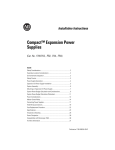
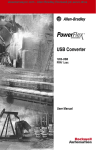
1
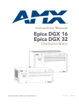
Application Solution
Controlling PowerFlex 4-Class Drives on
RS-485 Modbus RTU using MicroLogix
Controllers
Related Products and
Documentation
This document will guide you through the basic steps needed to install, start
up, and program PowerFlex 4-class drives for RS-485 Modbus RTU
communications. The information provided does not replace the user
manual, and is intended for qualified personnel only. All documentation
can be found on the Internet at www.theautomationbookstore.com using
either the public or private link.
Catalog Number Document Title
22A Series
PowerFlex 4 Adjustable Frequency AC Drive
User Manual
22B Series
PowerFlex 40 Adjustable Frequency AC Drive
User Manual
1761-NET-AIC
MicroLogix AIC+ Advanced Interface Converter
User Manual
1764-L Series
MicroLogix 1500 Programmable Logic Controllers
User Manual
(1)
Publication Number
22A-UM001C(1)-EN-E
22B-UM001A(1)-EN-E
1761-6.4
1764-UM001B(1)-EN-P
The letter represents document revision, and is subject to change.
Hardware That You Will Need
Many of the devices listed below may be or should be supplied with your
system, however these devices have been listed to help in the understanding
of the overall system application. You may not need all of the hardware
listed. For more information regarding firmware and revision levels, refer to
the table in Step 2 entitled Connecting the Hardware.
Product Name
PowerFlex 4-Class Drive
Catalog Number
22A-, or 22B-
MicroLogix AIC+ Advanced
1761-NET-AIC
Interface Converter
MicroLogix 1500 LRP Series C,
1764-LRP
Revision C, Firmware Version 9.0
Controller(2)
MicroLogix Programming Cable
1761-CBL-PM02
Belden 9841 Cable
(2)
None; user-supplied
Description
Device used to control the speed of a
motor.
Device used to interface a MicroLogix
controller with an RS-485 network.
Device also known as a Programmable
Logic Controller.
Device used to program a MicroLogix
controller.
Device used to connect a 1761-NET-AIC
converter to a PowerFlex 4-Class drive.
It is recommended that you use this controller type since it offers an additional programming port.
2
Controlling PowerFlex 4-Class Drives on RS-485 Modbus RTU using MicroLogix Controllers
What You Need To Do
• Step 1: Configure the hardware
• Step 2: Connect the hardware
• Step 3: Enter the Logic Status logic
• Step 4: Enter the Speed Feedback logic
• Step 5: Enter the Logic Command logic
• Step 6: Enter the Speed Reference logic
Supported Modbus Function Codes
Modbus Function Code
03
06
Command Description
Read Holding Registers
Preset (Write) Single Registers
Modbus devices can either be 0-based (registers are numbered starting at 0),
or 1-based (registers are numbered starting at 1). Since MicroLogix
controllers use 1-base technology, you will need to offset register addresses
by +1.
For example, the Logic Command word may be register address 8192 for
some master devices (e.g. ProSoft MVI56-MCM ControlLogix Modbus
scanner) and 8193 for others (e.g. MicroLogix and PanelViews).
Important MicroLogix Controller Information
Even though you may configure Channel 0 and Channel 1 for Modbus RTU
Master functionality, it is recommended that you dedicate Channel 0 for
RSLogix 500 software programming and ControlFLASH firmware
upgrading (based on customer statistics).
Channel 1 will not:
• allow you to flash upgrade controller firmware
• supply power to external devices (i.e. 1761-NET-AIC+)
While system setup is entirely up to the customer, using an external 24 VDC
power supply isolates the controller from the 1761-NET-AIC+ converter for
better noise immunity. Therefore, in this application example, Channel 1
has been dedicated as the Modbus RTU Master for drive control.
Controlling PowerFlex 4-Class Drives on RS-485 Modbus RTU using MicroLogix Controllers
3
Important RS-485 Wiring Information
Standard RS-485 wiring practices apply. Termination resistors need to be
installed at each end of the network cable to eliminate EMI noise induction
and to strengthen data signal. Also, RS-485 repeaters may need to be used
for long cable runs, or if greater than 32 nodes are needed on the network.
Step 1: Configuring the Hardware
This section will guide you through configuring a PowerFlex 4-class drive,
1761-NET-AIC converter, and MicroLogix 1500 LRP controller.
Device
PowerFlex 4 and 40 Drives
Steps
1. Set Parameters:
P036 [Start Source] to 5 “Comm Port”
P038 [Speed Reference] to 5 “Comm Port”
A103 [Comm Data Rate] to 4 “19.2K”
A104 [Comm Node Addr] to 1, or a unique node address
A107 [Comm Format] to 0 “RTU 8-N-1”
To Configure: You may use the LCD HIM, DriveExplorer
software version 3.01 or greater, or DriveExecutive software
version 2.01 or greater.
MicroLogix AIC+ Advanced
1. Set rotary switch to AUTO position.
Interface Converter, 1761-NET-AIC
MicroLogix 1500 LRP Series C,
Revision C, Firmware Version 9.0
Controller
1. Run RSLogix 500 programming software.
2. Create a project, or open an existing project.
3. In the left-hand project window, double-click the “Channel
Configuration” folder.
4. Click the “Channel 1” tab and set:
• Driver to Modbus RTU Master
• Baud to 19.2K
• Parity to NONE
• Control Line to No Handshaking
• InterChar. Timeout (x1 ms) to 0
• Pre Transmit Delay (x1 ms) to 0
5. Leave all other settings at default.
To Configure: You may only use RSLogix 500 software version
6.10.00 or greater. To verify software revision level, click Help
then About RSLogix 500 from the top menu bar.
4
Controlling PowerFlex 4-Class Drives on RS-485 Modbus RTU using MicroLogix Controllers
Step 2: Connecting the Hardware
➋
➊
➡
➌
➡
➡
➡
➡
➍
➏
➐
Drive Node 1
➎
➑
➒
Drive Node 247
B
C
O
M
SH
IE
G LD
N
D
A
TE
R
M
1761-NET-AIC
Terminal 16 if PowerFlex 4
Terminal 19 if PowerFlex 40
Install 120 ohm
termination resistor
if last drive.
NOTE: You may substitute a PowerFlex 4-class drive for a PowerFlex 7-class using a 20-COMM-H RS-485 HVAC adapter.
Wiring will be identical to the 1761-NET-AIC diagram above. Only jumper terminals TERM and A on the
adapters at the end of the RS-485 network, and only jumper terminals SHIELD and GND at a single
point (one device) on the network.
No.
➊
➋
➌
➍
➎
➏
➐
➑
➒
Description
MicroLogix 1500 LRP Series C, Revision C, Firmware Version 9.0 Controller
PowerFlex 4-Class Drive Frn 1.xxx and greater
Belden #3105A or equivalent cable
1761-CBL-PM02 MicroLogix Programming Cable. If this cable is not available, you may use a 1761-CB2-AC00 cable instead.
Channel 1 9-pin Female Serial Connector on MicroLogix 1500 LRP Controller (left side)
AK-U0-RJ45-TB2P Terminal Block Connector
1761-NET-AIC MicroLogix AIC+ Advanced Interface Converter Frn 1.xxx. You will need to supply converter with external 24 VDC power.
RS-485 Network Wiring Diagram
Second 1761-CBL-PM02 MicroLogix Programming Cable (for uploading/downloading programs to controller)
Controlling PowerFlex 4-Class Drives on RS-485 Modbus RTU using MicroLogix Controllers
5
Step 3: Entering the Logic Status Logic
Task
A
B
C
D
E
Description
Double-click the LAD 2 [MAIN] program folder and insert a ladder rung.
Double-click on the rung, and then copy-and-paste the following logic into the address bar: MSG MG10:0 3
LOCAL 1 1 N11:0 8449 1 2 132 SLOT:0
In a separate rung, double-click on the rung, and then copy-and-paste the following logic into the address bar:
BST XIC MG10:0/DN NXB XIC MG10:0/ER BND OTU MG10:0/EN
Click on Setup Screen to launch the message configuration window.
Configure the General tab by entering the information shown in the table below.
A
MSG
Read/Write Message
MSG File
MG10:0
Setup Screen
B
EN
DN
ER
MG10:0
MG10:0
U
EN
DN
C
MG10:0
D
ER
E
➊
➋
➌
➍
➎
➏
➐
No.
➊
➋
➌
➍
➎
➏
➐
Field
Channel:
Action
Select communication port
Recommended Setting
1
Modbus Command:
Select message function
03 Read Holding Registers (4xxxx)
Data Table Address:
Select an unused data file
N11:0 (user defined)
Size in Elements:
Element size = INT
1
Message Timeout:
Select control timeout in “seconds”
2
MB Data Address (1-65536): Select data register in drive
8449 (drive defined)
Slave Node Address (dec):
1
Select node address of drive
6
Controlling PowerFlex 4-Class Drives on RS-485 Modbus RTU using MicroLogix Controllers
Step 4: Entering the Speed Feedback Logic
Task
A
B
C
D
E
Description
Double-click the LAD 2 [MAIN] program folder and insert a ladder rung.
Double-click on the rung, and then copy-and-paste the following logic into the address bar: MSG MG10:1 3
LOCAL 1 1 N11:1 8452 1 2 128 SLOT:0
In a separate rung, double-click on the rung, and then copy-and-paste the following logic into the address bar:
BST XIC MG10:1/DN NXB XIC MG10:1/ER BND OTU MG10:1/EN
Click on Setup Screen to launch the message configuration window.
Configure the General tab by entering the information shown in the table below.
A
MSG
Read/Write Message
MSG File
MG10:1
Setup Screen
B
EN
DN
ER
MG10:1
MG10:1
U
EN
DN
C
MG10:1
D
ER
E
➊
➋
➌
➍
➎
➏
➐
No.
➊
➋
➌
➍
➎
➏
➐
Field
Channel:
Action
Select communication port
Recommended Setting
1
Modbus Command:
Select message function
03 Read Holding Registers (4xxxx)
Data Table Address:
Select an unused data file
N11:1 (user defined)
Size in Elements:
Element size = INT
1
Message Timeout:
Select control timeout in “seconds”
2
MB Data Address (1-65536): Select data register in drive
8452 (drive defined)
Slave Node Address (dec):
1
Select node address of drive
Controlling PowerFlex 4-Class Drives on RS-485 Modbus RTU using MicroLogix Controllers
7
Step 5: Entering the Logic Command Logic
Task
A
B
C
D
E
Description
Double-click the LAD 2 [MAIN] program folder and insert a ladder rung.
Double-click on the rung, and then copy-and-paste the following logic into the address bar: MSG MG10:2 6
LOCAL 1 1 N11:2 8193 1 2 128 SLOT:0
In a separate rung, double-click on the rung, and then copy-and-paste the following logic into the address bar:
BST XIC MG10:2/DN NXB XIC MG10:2/ER BND OTU MG10:2/EN
Click on Setup Screen to launch the message configuration window.
Configure the General tab by entering the information shown in the table below.
A
MSG
Read/Write Message
MSG File
MG10:2
Setup Screen
B
EN
DN
ER
MG10:2
MG10:2
U
EN
DN
C
MG10:2
D
ER
E
➊
➋
➌
➍
➎
➏
➐
No.
➊
➋
➌
➍
➎
➏
➐
Field
Channel:
Action
Select communication port
Recommended Setting
1
Modbus Command:
Select message function
06 Write Single Registers (4xxxx)
Data Table Address:
Select an unused data file
N11:2 (user defined)
Size in Elements:
Element size = INT
1
Message Timeout:
Select control timeout in “seconds”
2
MB Data Address (1-65536): Select data register in drive
8193 (drive defined)
Slave Node Address (dec):
1
Select node address of drive
8
Controlling PowerFlex 4-Class Drives on RS-485 Modbus RTU using MicroLogix Controllers
Step 6: Entering the Speed Reference Logic
Task
A
B
C
D
E
Description
Double-click the LAD 2 [MAIN] program folder and insert a ladder rung.
Double-click on the rung, and then copy-and-paste the following logic into the address bar: MSG MG10:3 6
LOCAL 1 1 N11:3 8194 1 2 0 SLOT:0
In a separate rung, double-click on the rung, and then copy-and-paste the following logic into the address bar:
BST XIC MG10:3/DN NXB XIC MG10:3/ER BND OTU MG10:3/EN
Click on Setup Screen to launch the message configuration window.
Configure the General tab by entering the information shown in the table below.
A
MSG
Read/Write Message
MSG File
MG10:3
Setup Screen
B
EN
DN
ER
MG10:3
MG10:3
U
EN
DN
C
MG10:3
D
ER
E
➊
➋
➌
➍
➎
➏
➐
No.
➊
➋
➌
➍
➎
➏
➐
Field
Channel:
Action
Select communication port
Recommended Setting
1
Modbus Command:
Select message function
06 Write Single Registers (4xxxx)
Data Table Address:
Select an unused data file
N11:3 (user defined)
Size in Elements:
Element size = INT
1
Message Timeout:
Select control timeout in “seconds”
2
MB Data Address (1-65536): Select data register in drive
8194 (drive defined)
Slave Node Address (dec):
1
Select node address of drive
Controlling PowerFlex 4-Class Drives on RS-485 Modbus RTU using MicroLogix Controllers
9
Understanding the I/O
The following table identifies drive I/O. In RSLogix 500 software, you will
need to know the data table address(es), and logic bit definiton(s) in order to
effectively control your drive. They are:
Data Table Address
N11:0
N11:1
N11:2
N11:3
Description
Logic Status Word; for bit definitons, please refer to Appendix C-4 of the
drive’s user manual.
Speed Feedback; for bit definitons, please refer to Appendix C-4 of the
drive’s user manual.
Logic Command Word; for bit definitons, please refer to Appendix C-3
of the drive’s user manual.
Speed Reference Word; for bit definitons, please refer to Appendix C-3
of the drive’s user manual.
Other Supported Controllers
Allen-Bradley offers additional MicroLogix controllers with Modbus RTU
Master capabilities. They are:
Controller Type
MicroLogix 1200 Series C, Revision C, Firmware Version 8.0
MicroLogix 1500 LSP Series C, Revision C, Firmware Version 9.0
Catalog Number
1762-L24, -L40
1764-LSP
Rockwell Automation Support
Before you contact Rockwell Automation for technical assistance, we
suggest that you please review the troubleshooting information contained in
the supporting product publications.
If the problem persists, call your local Allen-Bradley distributor or contact
Rockwell Automation in one of the following ways:
Phone
United States / Canada
•
•
Outside United States / Canada
You can access the phone number for your
country via the Internet:
1.262.512.8176 (7 AM - 6 PM CST)
1.440.646.5800 (24 hour support)
1. Go to http://www.ab.com
2. Click on Support (http://
support.rockwellautomation.com)
3. Under Contact Customer Support, click
on Phone Support
Internet
Email
➭
➭
Go to http://www.ab.com/support/abdrives
[email protected]
This document was written for Rockwell Automation by David M.
Wisniewski, Sr. Technical Support Engineer. All rights reserved.