1
BB702 Operation
3
AC Power Mains Input and Fuse Compartment:
The customer connects the power cord to the AC Power Input. As a safety
precaution, the power cord cannot be connected if the fuse compartment is open.
Refer to Section 5.3 for information on fuse replacement.
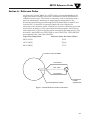
Reference Probe Connection:
The reference probe enables the user to monitor the target plate temperature
with an external instrument. The wires are connected to a Class A, 0.00385 RTD
Sensor.
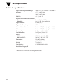
Refer to Section 6 for pinout details.
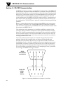
RS-232 Communications Port:
The female DB-9 port allows the customer to make a 3-wire RS-232 interface
with the BB-702. A detailed description of this port is described in Section 4.
3.3
Changing the Temperature Setpoint
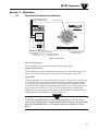
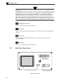
The layout of the front panel is shown in Figure 3. The BB702 incorporates a PID
digital setpoint controller. The upper display indicates the blackbody target plate
temperature known as (PV) Process Variable, while the lower display indicates
the programmed setpoint known as (SV) Setpoint Variable. Making changes to
the setpoint, units of measure and communication settings are made via the
"
" and "
" keys. Holding a key in, continuously, will cause the setpoint
temperature to advance more quickly to a desired value. Three scanning speeds
are provided: slow, medium and fast. The minimum and maximum setpoints are
locked.
3.4
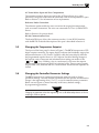
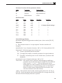
Changing the Controller Parameter Settings
The BB702 operates at its optimum performance when left with its factory
parameter settings. The only internal parameter that the operator should need to
change is the engineering units (°F or °C), or serial communications parameters.
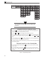
Below are two figures: a) menu hierarchy with factory default settings;
b) programming procedure.
CAUTION:
Changing any parameter other than engineering units could defeat safety features of the unit
rendering it unsafe to operate.
3-3