1
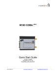
BusWorks® 900PB Series
ProfiBus/RS485 Network I/O Modules
Model 966PB-2004 Four Channel RTD Input Module
Model 966PB-2006 Six Channel RTD Input Module
USER’S MANUAL
ACROMAG INCORPORATED
30765 South Wixom Road
P.O. BOX 437
Wixom, MI 48393-7037 U.S.A.
Copyright 2002, Acromag, Inc., Printed in the USA.
Data and specifications are subject to change without notice.
Tel: (248) 624-1541
Fax: (248) 624-9234
8500-695-C04J008
2
BusWorks® 966PB Module User’s Manual
ProfiBus RTD Input
__________________________________________________________________
TABLE OF
CONTENTS
Symbols on equipment:
!
Means Refer to User’s Manual
(this manual) for additional
information”.
The information of this manual
may change without notice.
Acromag makes no warranty
of any kind with regard to this
material, including, but not
limited to, the implied
warranties of merchantability
and fitness for a particular
purpose. Further, Acromag
assumes no responsibility for
any errors that may appear in
this manual and makes no
commitment to update, or
keep current, the information
contained in this manual. No
part of this manual may be
copied or reproduced in any
form without the prior written
consent of Acromag, Inc.
IMPORTANT SAFETY CONSIDERATIONS
You must consider the possible negative effects of power, wiring,
component, sensor, or software failure in the design of any type of
control or monitoring system. This is very important where property
loss or human life is involved. It is important that you perform
satisfactory overall system design and it is agreed between you and
Acromag, that this is your responsibility.
GETTING STARTED
MOUNTING AND DIMENSIONS………………………
CONTROLS & INDICATORS..…………………………
ISOLATION BARRIERS..……………………………….
SETTING SLAVE ADDRESS…………………………..
CONNECTIONS………………………………………….
DIN-Rail Mounting And Removal………………
Network……………………………………………..
Power………………………………………………..
Analog Inputs……..……………………………….
Earth Ground..……………………………………..
TROUBLESHOOTING…………………………………..
Tips For Building ProfiBus Networks..……….
Top Four Common ProfiBus Problems……….
Troubleshooting Tools…………………………..
Using Connectors To Troubleshoot…………..
Diagnostics Function…………………………….
Diagnostics Table…………………………………
CALIBRATION…………………………………………...
3
3
3
4
4
4
5
6
7
7
8
8
8
8
9
9
10
11
TECHNICAL REFERENCE
KEY FEATURES…………………………………………
HOW IT WORKS………….……………………………..
SPECIFICATIONS……………………………………….
Model Numbers…………………………………..
Analog Inputs..………………....…………………
General Specifications…………………………..
Enclosure/Physical……………………………….
Agency Approvals…..…………………………….
Environmental……………………………………..
Communication Interface………………………..
Controls & Indicators…………………………….
Module Specific Parameters……………………
Data Types…………………………………………
12
13
14
14
14
15
15
16
16
17
19
19
20
Windows® is a registered trademark of Microsoft Corporation.
Profibus® is a registered trademark of ProfiBus Trade Organization.
All trademarks are the property of their respective owners.
_______________________________________________________________________________________
Acromag, Inc. Tel:248-624-1541 Fax:248-624-9234 Email:[email protected] http://www.acromag.com
BusWorks® 966PB Module User’s Manual
ProfiBus RTD Input
___________________________________________________________________
Rubber Plug - Pull To
Remove For Switch Access
(TB4 connections are present
for Model 966PB-2006 only)
TB4
TB3
DC-
DC+
Unit mounts to “T” type DIN
rails (35mm, type EN50022).
PWR
11 12 13 14 15 16
IN3-
IN2-
WARNING: IEC Safety
Standards may require that
this device be mounted within
an approved metal enclosure
or sub-system, particularly for
applications with exposure to
voltages greater than or equal
to 75VDC or 50VAC.
IN3L
IN3+
IN2+
TB2
IN1-
IN1+
IN1L
IN0-
IN0+
IN0L
TB1
2.34
(59.4)
RTD INPUTS 2,3
21 22 23 24 25 26
TB2
TB1
3.90
(99.1)
"T" RAIL DIN MOUNTING
DIN EN 50022, 35mm
4.35
(110.5)
NOTE: Dimensions Are INCHES (MILLIMETERS).
MODEL 966PB-2006 ENCLOSURE DIMENSIONS
REMOVE PLUG
TO ACCESS DP SLAVE
ADDRESS SWITCHES
(TB4 connections are present
for Model 966PB-2006 only)
TB4
TB3
CONTROLS &
INDICATORS
DC-
DC+
SLAVE
ADDRESS
(HEX)
RTD INPUTS 4,5
(966PB-2006 ONLY)
LRTN
LSD MSD 33 32 31
TB4
IN4-
IN4+
IN5-
IN5L
IN4L
46 45 44 43 42 41
TB3
RUN/PWR LED (GREEN)
BUS STATUS LED (YELLOW)
BUS
IN5+
Acromag
RUN
MOUNTING AND
DIMENSIONS
Units may be mounted sideby-side on 1-inch centers.
RTD INPUTS 0,1
1.05
(26.7)
LRTN
IN4-
IN4+
IN4L
IN5-
IN5L
RTD INPUTS 4,5
(966PB-2006 ONLY)
IN2L
PROFIBUS
LSD MSD 33 32 31
SLAVE
ADDRESS
(HEX)
3.75
(95.3)
CL
IN5+
46 45 44 43 42 41
BUS
4.68
(118.9)
RUN
TB3
TB4
Acromag
3
PWR
Green Run LED will stay ON if
power is on and unit is OK,
and will blink if unit fails.
PROFIBUS
IN3-
IN3L
IN3+
IN2-
IN2+
IN2L
TB2
IN1-
IN1L
IN1+
IN0L
IN0-
11 12 13 14 15 16
21 22 23 24 25 26
TB2
TB1
963/964PB
ISOLATION
DIAGRAM
Yellow BUS LED will turn ON if
module is properly connected
to the network and in data
exchange mode.
RTD INPUTS 2,3
ANALOG INPUTS
PWR
TB4
RTD INPUTS 4,5
(966PB-2006 ONLY)
DC+
DC-
LSD MSD 33 32 31
SLAVE
ADDRESS
(HEX)
PWR
IN3L
IN3-
IN3+
IN2L
IN2-
IN2+
TB2
IN1-
RTD INPUTS 2,3
IN1L
IN1+
IN0L
IN0-
IN0+
RTD INPUTS 0,1
TB1
Dashed Lines denote isolation
barriers.
The input circuit, network, and
power circuits are isolated
from each other for safety and
noise immunity.
5V
5V
NETWORK
ISOLATION BARRIERS
TRANSFORMER
OPTICAL
11 12 13 14 15 16
TB3
TB3
LRTN
IN4-
IN4+
IN4L
IN5+
IN5-
IN5L
46 45 44 43 42 41
TB4
REMOVABLE
(PLUG-IN TYPE)
TERMINAL BLOCKS
IN0+
PROFIBUS CONNECTOR
DB9 FEMALE
TB1
RTD INPUTS 0,1
21 22 23 24 25 26
TB2
TB1
ANALOG INPUTS
ANALOG INPUTS
_______________________________________________________________________________________
Acromag, Inc. Tel:248-624-1541 Fax:248-624-9234 Email:[email protected] http://www.acromag.com
4
BusWorks® 966PB Module User’s Manual
ProfiBus RTD Input
__________________________________________________________________
HEX ADDRESS
MSD LSD
x16 x1
Remove Rubber Plug
To Access Address
Switches
SETTING SLAVE
ADDRESS
Address is set to 126 (7EH)
from the factory. This address
is reserved for commissioning
purposes only.
TOP EDGE VIEW
EF 0 1 2
EF 0 1 2
D
3 D
3
4 C
4
C
5 B
5
B
A9 76
A9 76
8
8
SET SWITCHES TO A VALID SLAVE ADDRESS FROM 0 TO 125 (00H TO 7DH)
Locate hexadecimal address
switches in recessed opening
next to power terminals
(remove rubber plug).
1. Choose a slave address from 0-125 and locate highest MSD number less
than this address. Set MSD switch to this number's corresponding HEX digit.
MSD
x16 HEX
LSD DEC
x1 HEX
1
Use a screwdriver to rotate
these switches to set a unique
valid address from 0 to 125.
2
0
0
0
16 32 48 64 80 96 112 128 144 160 176 192 208 224 240
1 2 3 4 5 6 7 8 9 A B C D E F
1 2 3 4 5 6 7 8 9 10 11 12 13 14 15
0
1
2
3
4
5
6
7
8
9
A
B
C
D
E
F
2. Determine the DECimal remainder and set the LSD switch to its
corresponding HEX digit.
3. Replace the rubber plug (if present) over this switch opening
to shield circuit from debris.
If the switches are set to a
valid address from 0-125, then
the switch setting determines
the slave address and the Set
Slave Address software
command will be rejected.
If these switches are instead
set to 126 (7EH) upon powerup (or 126 to 254), the unit will
retrieve its address from the
internal EEPROM, which is
modified via the Set Slave
Address command.
If these switches are set to
255 (FFH) upon power-up, this
will return the address in
EEPROM to 126 (7EH).
The address stored in the internal EEPROM is modified via the Set Slave
Address command. If the address switches are set to 126 (or 126 to 254)
upon power-up, the module will retrieve the last address stored within its
EEPROM (126 from the factory). With both the internal EEPROM and
external switch addresses set to 126, the unit will await the Set Slave
Address command after power-up, before proceeding to the
parameterization state (address 126 cannot be used in data exchange mode
and is reserved for commissioning purpose only). You must use the Set
Slave Address command to change the internal (EEPROM) address
following power-up in order to proceed. However, if the switches are set to
an address less than 126 upon power-up, then the switches determine the
slave address and the EEPROM setting is ignored. You can later restore the
internal EEPROM setting to 126 by powering the unit up with the address
switches set to 255 (FF). You would then power the unit up again with these
switches set to 126 in order to place the unit in commissioning mode.
CONNECTIONS
PUSH
MODULE REMOVAL
FROM DIN RAIL
TB3
DC-
LSD MSD 33 32 31
SLAVE
ADDRESS
(HEX)
DC+
46 45 44 43 42 41
TB4
DIN-Rail
Mounting
& Removal
USE YOUR FINGER TO APPLY
DOWNWARD PRESSURE HERE
AS YOU LIFT AND TILT MODULE
TO REMOVE IT FROM RAIL
PWR
"T" TYPE
DIN RAIL
11 12 13 14 15 16
TB2
TB1
Any Series 9XXPB ProfiBus Module
21 22 23 24 25 26
Remove Terminal Blocks On This
Side To Provide Clearance
PRY WITH SCREWDRIVER
INSERTED IN SLOT HERE
(DO NOT TWIST TO AVOID
DAMAGING PLASTIC TAB)
When attaching the module to the T-type DIN
rail, angle the top of the unit towards the rail
and locate the top groove of the adapter over
the upper lip of the rail. Firmly push the unit
towards the rail until it snaps into place. To
remove, first separate the input terminal
block(s) from the bottom side of the module to
create a clearance to the DIN mounting area.
Next, while holding the module in place from
above, insert a screwdriver into the lower arm
of the DIN rail connector and use it as a lever
to force the connector down until the unit
disengages from the rail (do not twist the
screwdriver to avoid damaging plastic).
PUSH SCREWDRIVER AS SHOWN
TO TILT AND LIFT MODULE OFF RAIL
_______________________________________________________________________________________
Acromag, Inc. Tel:248-624-1541 Fax:248-624-9234 Email:[email protected] http://www.acromag.com
BusWorks® 966PB Module User’s Manual
ProfiBus RTD Input
___________________________________________________________________
CONNECTIONS
Siemens ProfiBus Connector
9
5
Network
3
8
4
DB9
(Male)
7
2
Grn
Insul Shld
Green Wire = A
Red Wire = B
IN OUT
Network
Do not mix RS485 A & B connections. Green wire is A, red wire is B.
You MUST terminate the network at both ends only.
Termination resistors are integrated in the ProfiBus connector.
When you switch termination ON, the out-going connections
are disconnected from the network.
RTD INPUTS 4,5
TB3
DC+
DC-
SLAVE
ADDRESS
(HEX)
LRTN
TB4
IN4-
IN4+
IN5-
LSD MSD 33 32 31
The connector must have builtin inductors in order to operate
at the higher baud rates.
11 12 13 14 15 16
IN3L
IN3-
IN2+
TB2
IN1-
RTD INPUTS 2,3
IN1L
IN1+
IN0-
IN0+
IN0L
RTD INPUTS 0,1
TB1
966PB-2004 ACRO0702.GSD
Ident_Number=0702 Hex
966PB-2006 ACRO0701.GSD
Ident_Number 0701 Hex
ProfiBus Connector
ProfiBus Socket
(DB9 Female)
When building cables, do not
mix A & B connections. Green
wire is A, Red wire is B.
PWR
(966PB-2006 ONLY)
IN3+
PROFIBUS
PVC
Sheath
Use ProfiBus cable
per DIN 19245 and
EN 50170.
46 45 44 43 42 41
IN5+
BUS
IN4L
RUN
Always use ProfiBus cable per
DIN 19245 and EN 50170.
GSD Files:
IN5L
Acromag
DB9 CONNECTIONS
1 Shield
2 No Connection
3 Data A
4 Request To Send
5 Ground
6 +5V
7 No Connection
8 Data B
9 No Connection
0.35
0.30
IN2L
ProfiBus
Cable
(Violet)
Red
6
R
on
off
off
IN2-
on
Use ProfiBus connectors
similar to the one shown at left
(Siemens version shown).
Strip Cable
Similar to Shown
AB
0.25
1
Termination
Switch
5
21 22 23 24 25 26
R
on
off
FRONT
VIEW
ProfiBus
Cable
IN OUT Green Wire = A
Network Red Wire = B
RIGHT SIDE VIEW
Network Length
Use Type A ProfiBus cable per EN 50170. Keep line lengths less than the
length indicated below for your transmission rate. For baud rates not shown,
the lower length of the closest range end points apply (i.e. 100M at 3Mbps).
Bus Segment Length Limit Per Baud Rate For Type A Bus Cable
BAUD
9.6K
19.2K
93.75K 187.5K 500K
1.5M
12M
Type A 1200M 1200M 1200M 1000M 400M
200M
100M
IMPORTANT: Do not connect
earth ground to logic Ground
(DB9 Pin 5). Earth Ground
should connect to cable Shield
(common to DB9 Pin 1).
Note that Acromag modules
also support the optional RTS
direction control signal at Pin
4.
_______________________________________________________________________________________
Acromag, Inc. Tel:248-624-1541 Fax:248-624-9234 Email:[email protected] http://www.acromag.com
6
BusWorks® 966PB Module User’s Manual
ProfiBus RTD Input
__________________________________________________________________
CONNECTIONS
Termination
Network
The network must be terminated at both ends only. Most ProfiBus
connectors include a switch for termination as shown above. Note that this
switch will also disconnect the outgoing network signal.
Example ProfiBus System
Connections
A network segment may contain up to 32 nodes without the use of a signal repeater.
Transmission distance is up to 1200 meters per segment without a repeater.
Termination must be placed at both ends of a network or network-segment.
Acromag
RUN
Voltage
12VDC
15VDC
24VDC
36VDC
Current
217mA
162mA
102mA
69mA
PROFIBUS
61
NODE 32'
on
off
31
Acromag
Acromag
PROFIBUS
PROFIBUS
RUN
BUS
RUN
BUS
RS485 SIGNAL
REPEATER
TERMINATION
SWITCH
on
on
off
NODE 2'
off
30
NODE 32
NODE 1'
NODE 31
END OF SEGMENT
(TERMINATION ON)
START OF SEGMENT
(TERMINATION ON)
END OF NETWORK
(TERMINATION ON)
on
off
4
NODE 5
SEGMENT 2 (UP TO 1200 METERS,
UP TO 32 NODES PER SEGMENT)
PROFIBUS MASTER
PLUG-IN CARD
INSTALLED IN PC.
NETWORK LENGTH PER
BAUD RATE w/ TYPE A
PROFIBUS CABLE
BAUD
9600bps
19.2Kbps
93.75Kbps
187.5Kbps
500Kbps
1.5Mbps
12Mbps
LENGTH
1200M
1200M
1200M
1000M
400M
200M
100M
START OF NETWORK
(TERMINATION REQD)
PROFIBUS MASTER - A
HOST PC WITH PROFIBUS
CARD INSTALLED AND
RUNNING APPLICATION
SOFTWARE.
Acromag
Acromag
Acromag
PROFIBUS
PROFIBUS
PROFIBUS
RUN
BUS
RUN
on
1
NODE 1
NODE 2
PROFIBUS RS485 NETWORK
off
BUS
RUN
on
2
off
NODE 3
BUS
on
3
off
NODE 4
SEGMENT 1 (UP TO 1200 METERS, UP TO 32 NODES PER SEGMENT)
NOTE: THE PROFIBUS CONNECTORS SHOWN HAVE A TERMINATION NETWORK BUILT-IN.
WITH TERMINATION ON, THE OUTGOING CABLE IS DISCONNECTED FROM NETWORK. SWITCH
TERMINATION ON ONLY AT THE BEGINNING AND END OF A NETWORK OR NETWORK SEGMENT.
9
Power
The total number of nodes and total distance may be extended by using signal repeater(s).
The maximum number of modules possible is further limited by the address range from 0 to 125.
Connect 12-36V DC to the power terminals labeled DC+ & DC-. For
supply connections, use No. 14 AWG wires rated for at least 75°C.
Observe proper polarity. CAUTION: Do not exceed 36VDC peak.
OBSERVE PROPER POLARITY
12 TO 36VDC
EARTH
GROUND
TB3
TB3
DC+
DC-
PWR
TIP: A recommended RS485
repeater for ProfiBus is the
Siemens 6ES79720AA010XA0.
PROFIBUS
BUS
INPUT POWER
IS ISOLATED
LRTN
SLAVE
ADDRESS
(HEX)
Note: 12Mbps installations
require a minimum cable
length of 1M between stations.
RUN
LSD MSD 33 32 31
Up to 125 slave modules may
network together with a class 1
master using four repeaters
(one repeater every 31 nodes).
Address 0 is typically reserved
for the class 1 master.
Acromag
BUS
Note that earth ground is connected to the LRTN terminal as shown above
and is not connected to the inputs.
CAUTION: Risk of Electric Shock – More than one disconnect switch may
be required to de-energize equipment before servicing.
IMPORTANT – External Fuse: If unit is powered from a supply capable of
delivering more than 1A to the unit, it is recommended that this current be
limited via a high surge tolerant fuse rated for a maximum current of 1A or
less (for example, see Bel Fuse MJS1).
_______________________________________________________________________________________
Acromag, Inc. Tel:248-624-1541 Fax:248-624-9234 Email:[email protected] http://www.acromag.com
7
BusWorks® 966PB Module User’s Manual
ProfiBus RTD Input
___________________________________________________________________
IN0L
IN1+
IN1IN1L
TB1
EARTH
GROUND
NOTE 1
DO NOT
GROUND
TB1
TB1
IN0+
IN0IN0L
IN1+
IN1IN1L
Input is Cu, Pt, or Ni RTD, or
resistance, connected in 2wire, or 3-wire fashion.
RTD INPUTS 0,1
IN0-
16 15 14 13 12 11
EARTH
GROUND
TB1
IN0+
RTD INPUTS 0,1
16 15 14 13 12 11
NOTE 1
Inputs are not isolated
channel-to-channel.
JUMPER [IN-] TO [INL]
FOR 2-WIRE RTD
NOTE 1: DO NOT APPLY EARTH GROUND TO INPUT LEADS OR INPUT
TERMINALS. EARTH GROUND SHOULD INSTEAD BE APPLIED AT THE
INPUT LOGIC GROUND TERMINAL (LRTN AT TB3-33).
Unused inputs should be
terminated and not left floating.
IMPORTANT: RTD INPUTS ARE NOT
ISOLATED CHANNEL TO CHANNEL
For 2-wire connections, be
sure to jumper the IN- and
INL leads together.
JUMP
JUMPER [IN-] TO [INL] FOR
RESISTANCE BOX OR 2-WIRE
TB1
IN0+
IN0IN0L
IN1+
IN1IN1L
RTD INPUTS 0,1
16 15 14 13 12 11
RESISTANCE
DECADE BOX
TERMINATE UNUSED
INPUT CHANNELS
R
TB1
TB1
R
TB1
IN0+
IN0IN0L
IN1+
IN1IN1L
RTD INPUTS 0,1
UNUSED INPUTS
RESISTANCE INPUT
16 15 14 13 12 11
DO NOT
GROUND
Analog Inputs
2-WIRE RTD
3-WIRE RTD
9
CONNECTIONS
Connect analog input signals to the input terminals as shown below
according to your signal type. Note earth ground.
JUMP
9
Do not attach earth ground
to any input leads. Earth
ground should connect to
the LRTN terminal at TB3-33.
DO NOT LEAVE UNUSED
INPUTS FLOATING
Earth Ground
Connect Earth Ground as shown in the connection drawings above.
Note that earth ground is connected to the LRTN terminal and should
not connect to the inputs. Additionally, ground the ProfiBus cable as
shown in the drawing below. The ground connections noted are
recommended for best results. If sensors are already grounded, use
caution and avoid making additional ground connections which could
create ground loops.
Warning: To comply with safety and performance standards, use
shielded cable and connect earth ground as noted. Failure to use good
wiring and grounding practices may be unsafe and hurt performance.
The plastic module housing does not require earth ground.
PROFIBUS WIRING AND GROUND
PROFIBUS
CONNECTOR
1. Always connect the cable shield to earth ground at both
ends as shown.
2. If the field device does not include an earth ground
screw, it may be necessary to strip the cable insulation
near the field device and clamp the cable shield to a local
grounding bar or surface as shown.
EARTH GROUND SCREW
ON EQUIPMENT (WHEN
AVAILABLE)
THE SHIELD IS COMMON TO
THE HOUSING (FOR METAL
ENCLOSURES).
PROFIBUS FIELD DEVICE
R
on
off
OUT
GROUND
CLAMP
ACROMAG MODULES:
The metal shroud of the DB9 ProfiBus connector on
Acromag modules is common to pin 1 of the DB9
connector (SHIELD). This is also common to the
cable shield which must be earth grounded. Acromag
modules are enclosed in plastic and do not
provide a dedicated earth ground screw. As such,
a local earth ground connection to the cable shield
must be made as shown above.
R
on
off
CABLE
SHIELD
EARTH GROUND SCREW
ON EQUIPMENT (WHEN
AVAILABLE)
INP
NOTE: If a potential difference exists between
earth grounding points, an equalization current
can flow through the cable shield when connected
at both ends. In this case, it may be necessary to
install an additional potential equalization line between
field locations to minimize this current as shown here.
CABLE
SHIELD
EQUIPOTENTIAL BONDING STRIP
(IF NECESSARY--SEE NOTE)
PROFIBUS CABLE
GROUND
CLAMP
THE SHIELD IS COMMON TO
THE HOUSING (FOR METAL
ENCLOSURES).
Use ProfiBus cable
per DIN 19245 and
EN 50170.
Use only approved cables
with braided shields of
density greater than 80%.
Green Wire = A
Red Wire = B
AB
Grn
PROFIBUS FIELD DEVICE
Shld Red
GROUNDING:
Insul
PROFIBUS
CONNECTOR
PVC
Sheath
_______________________________________________________________________________________
Acromag, Inc. Tel:248-624-1541 Fax:248-624-9234 Email:[email protected] http://www.acromag.com
8
BusWorks® 966PB Module User’s Manual
ProfiBus RTD Input
__________________________________________________________________
TROUBLESHOOTING
Tips For Building
ProfiBus Networks
The module routinely performs internal diagnostics following power-up
or reset. During this period, the green “Run” LED will flash for a moment. If
the diagnostics complete OK, the “Run” LED will stop flashing after a few
seconds and remain ON. This indicates the unit is operating normally.
Once the unit has passed through the initialization, parameterization, and
configuration states, and is in data exchange mode, the yellow BUS LED will
be ON. If the BUS LED is OFF and the unit is connected to the network,
then this is indicative of an initialization problem.
•
•
•
•
•
•
•
•
•
•
•
Top Four Common
ProfiBus Problems
Troubleshooting Tools
Follow the ProfiBus installation guidelines.
Use the recommended cable and connectors of the standard.
Verify that none of the wires are broken or shorted.
Don’t mix up the A & B lines. Green wire is A, red wire is B.
Do not exceed the recommended segment length for the baud rate.
Make sure that there are no more than 32 RS-485 devices per
segment (including the master device and the repeater).
Check for proper termination of all copper-wire network segments
(an RS-485 segment must have a termination resistor at both ends
of the segment only).
All activated terminations must be powered all the time. If this is not
possible, then consider using an active-termination box.
Check whether the station address is set to the correct value.
If your network connects between buildings or runs through
hazardous environments, consider the use of fiber-optics.
Avoid drop lines and keep their length within the specified maximum.
If you employ T-drops, consider using repeaters and active-bus
terminations.
1. Incorrect slave address set at the slave.
2. ProfiBus connector between the master and slave has its
termination switch turned ON.
3. Incorrect module configuration sent to slave.
4. Configuration is based on outdated GSD file information.
There are several models of handheld devices on the market that
simplify the installation and troubleshooting of ProfiBus networks. The more
sophisticated units include LCD displays that read out errors directly. Two of
these of these devices are referenced below:
Hand-Held ProfiBus Network Maintenance Tools
Manufacturer
Part Number
Special Features
Siemens
BT 200
Primarily a Cable Tester
Comsoft
NetTest II Set
Includes DP Mono-Master
4000-7-06C-J
Functionality
In general, these devices can be used to check the network wiring
before devices are connected to the bus and are often used to indicate:
•
•
•
•
Whether the A and B lines have been switched.
Whether a short exists between the A & B lines and shield.
The occurrence of a wire-break in the A or B line, or shield line.
Improper termination.
_______________________________________________________________________________________
Acromag, Inc. Tel:248-624-1541 Fax:248-624-9234 Email:[email protected] http://www.acromag.com
BusWorks® 966PB Module User’s Manual
ProfiBus RTD Input
___________________________________________________________________
These tools can also be used to check the RS-485 interface of a
ProfiBus device after it has been connected and may include the following:
•
•
•
•
The ability to create a list of all stations connected to a network
(useful for identifying missing or “offline” devices).
Can test individual stations and help identify duplicate addresses.
Can measure the distance along a network segment to verify if it
complies with the Profibus requirements for distance and data rate.
They can detect signal reflections along the network, useful for
locating bus line interruptions and discontinuities.
9
TROUBLESHOOTING
Troubleshooting Tools
Acromag strongly suggests the use of these tools for building and
maintaining ProfiBus networks. Note that Profichip also offers a Profibus
connector (PA003100) that includes 4 network diagnostic LED’s that may be
helpful in trouble-shooting your network (see table below).
The standard 9-pin ProfiBus connectors with integrated termination
resistors are also helpful in troubleshooting segments of the network. In
most of these connectors, when the termination resistors are switched ON,
the outgoing portion of the connector is disconnected. As such, you can
selectively disable segments of the network until you find the branch that is
causing the problem. For example, if your handheld unit is connected to the
beginning of a network and indicates a wire break, you can selectively switch
off portions of the network and recheck your handheld unit to help pin point
the portion of the network that is causing the problem. Below are some
ProfiBus connectors that we recommend:
Preferred Bus Connectors
Manufacturer
Part Number
Siemens
6ES7972-0BA12-0XA0
Siemens
6ES7972-0BB12-0XA0
Profichip
PA003100
Using Connectors To
Troubleshoot
Special Features
Switchable Termination
Adds PB Interface (Piggy
Back DB9 For Diagnostic
Connection)
Adds PB Interface and Four
Diagnostic LED’s For TroubleShooting.
ProfiBus includes a rich diagnostic function that can be used to
troubleshoot ProfiBus devices. This function contains 6 bytes of standard
diagnostic information, plus up to an additional 238 bytes of device specific
diagnostic information. Most configuration tools support this command and
can read the diagnostic information from the Profibus device.
Diagnostics Function
_______________________________________________________________________________________
Acromag, Inc. Tel:248-624-1541 Fax:248-624-9234 Email:[email protected] http://www.acromag.com
10
BusWorks® 966PB Module User’s Manual
ProfiBus RTD Input
__________________________________________________________________
Diagnostics Table
If your problem still exists after
checking your wiring and
reviewing this information, or if
other evidence points to
another problem with the unit,
an effective and convenient
fault diagnosis method is to
exchange the module with a
known good unit. Acromag’s
Application Engineers can
provide further technical
assistance if required.
Complete repair services are
also available from Acromag.
SYMPTOM
Yellow BUS LED
does not light.
Yellow BUS LED
turned OFF.
Cannot
communicate.
POSSIBLE CAUSE
Initialization Problem.
LED ON if module in
data exchange state.
Both the internal
EEPROM and
external address
switches are set to
an address of 126.
Communication
Halted.
Is power ON at the
module and/or
RS485 converter?
Is address correct?
Is the termination
switch of the
Profibus connector at
the prior node turned
on?
Continuous flashing
green RUN LED.
Many
Communication
Errors.
Internal firmware
problem.
Missing Termination
Resistors?
Is baud rate too high
for distance?
POSSIBLE FIX
Check Station Address. Is
GSD file correct. Check for
wiring error.
Module is awaiting Set Slave
Address command in order
to complete initialization.
Alternately, set switches
from 0-125 and re-power.
Turn power off and then ON
to reset unit. Investigate
grounding.
Check power. Is green
RUN LED ON?
Check address settings at
the slave.
Switch Termination on only
at the ends of the network.
With termination switch on,
the outgoing connections
are disconnected from the
network chain.
Return the module for
service.
Termination resistors must
be placed only at both ends
of a network or network
segment.
Maximum distance is limited
below 1200 meters as baud
rate is increased above
93.75Kbps (see Table).
_______________________________________________________________________________________
Acromag, Inc. Tel:248-624-1541 Fax:248-624-9234 Email:[email protected] http://www.acromag.com
BusWorks® 966PB Module User’s Manual
ProfiBus RTD Input
___________________________________________________________________
There are six calibration channels for these models. The following table
gives the calibration values for supported input ranges. These are the input
signals required to calibrate the range endpoints. If calibration is required, it
is recommended that all ranges of the unit be done.
INPUT RANGE
Pt 100Ω (-200 to +850ºC), α=1.3850
Pt 100Ω (-200 to +850ºC), α=1.3911
Ni 120Ω (-80 to +320ºC), α=1.6720
Cu 10Ω (-200 to +260ºC), α=1.4272
0 to 500Ω Linear, α=1.000
Low Calibration
0°C (100Ω)
0°C (100Ω)
0°C (120Ω)
0°C (9.04Ω)
10.00Ω
High Calibration
850°C (390.48Ω)
850°C (395.12Ω)
300°C (439.44Ω)
250°C (18.73Ω)
450.00Ω
These models have two I/O Configuration definitions in their GSD files,
one for normal operation, and another for accomplishing calibration. The
normal data exchange definition supports 6 input words (12 input bytes
representing your measured values). A second calibration definition
supports 6 input words and 6 output words. The master software will allow
you to choose which mode the slave will assume—Input Mode or
Configuration Mode. The method used to transfer information between the
master and slave will vary widely between systems. The steps below
represent the minimum steps necessary to accomplish software calibration.
If you choose to perform calibration and select Configuration Mode, the
master will download the 6I/6O word configuration during the startup
sequence, and the module may then be calibrated as follows:
1. With your master software, select the “Configuration Mode” from the
GSD file when setting up the master to communicate with the module.
2. With user parameter bytes 0 & 1, set the ranges that are to be calibrated.
3. Apply the zero calibration signal (see table of prior page) to the input to
be calibrated and allow the input to settle a few seconds.
4. Write FFH into the low-order byte of the channel’s output word several
times (to ensure transmission). In Configuration Mode, the module will
automatically calibrate the channel’s zero value when FFH is detected.
Then write 00H into the low-order byte to complete zero calibration.
5. Apply the full-scale calibration signal (Cal Hi, see table) to the input to be
calibrated and allow the input to settle a few seconds.
6. Write FFH into the high-order byte of the channel’s output word several
times to ensure transmission. In Configuration Mode, the module will
automatically calibrate the channel’s full-scale value when FFH is
detected. Then write 00H into the high-order byte to complete full-scale
calibration.
7. Repeat steps 3-6 for the other channels of the same range.
8. With user parameter bytes 0-5, select the next range to be calibrated.
9. Repeat steps 3-7 for all channels of this range.
10. Repeat steps 8-9 until all input ranges have been calibrated.
11. When finished calibrating, use the master software to return the module
to the normal “Input Mode” to prevent miscalibration.
11
CALIBRATION
IMPORTANT: This module
has already been calibrated at
the factory and recalibration is
not normally required, except
as necessary to correct for
long term component aging, or
to satisfy your company’s
maintenance requirements.
Do not attempt to recalibrate
this module unless absolutely
required, as miscalibration will
negatively affect the module’s
performance.
For best results, be sure to
use a precision signal source
capable of reproducing the
nominal endpoint signals
shown below, at least as
accurate as the module itself
(better than ±0.1% of span).
Always allow the module to
warm up a few minutes prior to
calibration.
After completing calibration, the module should be reconfigured as
required and placed in the normal “Input Mode” configuration (I/O
configuration is 6 input words only). In general, your software allows you to
select the normal “Input Mode” configuration, and the slave will then be
taken off-line by the master and reconfigured. If reconfiguration is
successful, the slave module will pass to the data exchange state with a
normal I/O configuration.
_______________________________________________________________________________________
Acromag, Inc. Tel:248-624-1541 Fax:248-624-9234 Email:[email protected] http://www.acromag.com
12
BusWorks® 966PB Module User’s Manual
ProfiBus RTD Input
__________________________________________________________________
TECHNICAL REFERENCE
KEY FEATURES
•
•
•
•
•
•
•
•
•
•
•
•
•
•
•
•
•
•
•
•
•
•
PTO Certified - Unit certified by the ProfiBus Trade Organization.
Safety Agency Approvals – CE marked, UL, & cUL listed, Class 1;
Division 2; Groups A, B, C, D approvals.
Fully Independent Slave w/ Direct I/O Connection – This selfcontained unit does not require special bus couplers, power supplies, or
a rack mount to operate.
Plug-In Terminal Blocks & DIN-Rail Mount - Make mounting, removal,
and replacement easy. Barrier strip and spring-clamp type terminals are
also available as an option.
Industry Standard ASIC – Uses Siemens SPC3 intelligent ASIC to talk
ProfiBus.
Isolated RS485/ProfiBus Network Interface – Highly immune to noise
and can operate over long distances. Allows many modules to network
together.
Flexible Quad or Hex RTD Inputs - Accepts four or six channels of
input for Platinum (Pt), Copper (Cu), and Nickel (Ni) RTD types, or
simple resistance. RTD’s are connected in 2 or 3 wire fashion.
Linearization, excitation, lead break detection, and lead-wire
compensation (3-wire) are included.
Ratiometric Differential RTD Sampling – The RTD is sampled
differentially using ratiometric conversion and this increases accuracy.
Automatic Self-Calibration – Built-in self-calibration helps correct for
temperature drift of the input circuit every 60 seconds.
Upscale Or Downscale Break Detection – Inputs may be configured to
go upscale or downscale upon lead breakage.
Auto-Baud Rate Detection – The baud rate is set automatically.
High-Speed Data Rates – Half-duplex RS485 up to 12M baud.
Includes RTS Support – ProfiBus interface includes the optional RTS
(Request-To-Send) direction control.
Precise High-Resolution A/D Conversion – Modules use highresolution, low noise, sigma-delta analog-to-digital conversion for high
accuracy and reliability.
Nonvolatile Reprogrammable Memory – Allows the functionality of this
device to be reliably reprogrammed thousands of times.
Fully Isolated – Input channels (as a group), network, and power are all
isolated from each other for safety and increased noise immunity.
LED Indicators – A green LED indicates power. A yellow bus LED
indicates proper network connection and unit in data exchange mode.
Watchdog Timer Built-In – Standard for the ASIC and operates in the
data exchange mode if communication with the master is lost.
Self-Diagnostics & Diagnostic Watchdog - For easy maintenance
and troubleshooting. Includes a hardware watchdog timer built into the
microcontroller that causes it to initiate a self reset if the controller ever
“locks up” or fails to return from an operation in a timely manner.
Wide-Range DC-Power - Diode-coupled power provides reverse
polarity protection and may be used with redundant supplies, and/or
battery back-up.
Hardened For Harsh Environments - For protection from RFI, EMI,
ESD, EFT, & surges. Has low radiated emissions per CE requirements.
Wide Ambient Operation – Reliable over a wide temperature range.
_______________________________________________________________________________________
Acromag, Inc. Tel:248-624-1541 Fax:248-624-9234 Email:[email protected] http://www.acromag.com
BusWorks® 966PB Module User’s Manual
ProfiBus RTD Input
___________________________________________________________________
These input modules will process up to four or six RTD input signals,
according to model number, and provide an isolated RS485 ProfiBus
interface for configuring and monitoring the inputs. One A/D is provided for
every pair of input channels and each input drives a separate A/D channel.
An integrated multiplexer and analog switch are used to connect each of two
A/D input channels to the A/D converter. The A/D converter then applies
appropriate gain to these signals, performs analog-to-digital conversion, and
digitally filters the signals. The digitized A/D signal is then transmitted
serially to a microcontroller. The microcontroller completes the transfer
function according to the input type/range per its embedded program.
Configuration and calibration parameters are stored in non-volatile memory
integrated within the microcontroller. These modules implement the
ProfiBus protocol via an industry-standard SPC3 ASIC from Siemens. This
ASIC acts like a RAM or UART chip to the internal microcontroller and
completely handles the requirements of the protocol standard. The ASIC will
transfer network data to the microcontroller and automatically provide the
response to the bus. The ASIC handles the ProfiBus protocol and
communicates with the network via an optically isolated RS485 transceiver.
A wide input switching regulator (isolated flyback) provides isolated power to
the input circuit and the RS485 port. Refer to the simplified schematic below
to gain a better understanding of the circuit.
HOW IT WORKS
966PB SIMPLIFIED SCHEMATIC
1+
ISOLATED RS485
1R+
A/D #1
PWR
LED
BUS
LED
+5V
+5V
RTS
22+
PROFIBUS
SPC3 SLAVE
ASIC
MICRO
CONTROLLER
1+
1R+
13
A/D #2
RS485
PROFIBUS
TRANSCEIVER
4
DB9
SHLD
4
2-
N
E
T
W
O
R
K
ADDRESS
BUFFER
2+
EF 0 1 2
3
D
C
4
5
B
A9 76
8
EF 0 1 2
3
D
4
C
B
5
A9 7 6
8
1+
ISOLATED INPUT POWER
1R+
2-
A/D #3
12-36VDC
ISOLATED SECONDARIES
NETWORK
POWER
5V
2+
ISOLATED
FLYBACK
SWITCHER
DC+
DC-
5V
LRTN
100
INPUT/LOGIC
POWER
EARTH
GROUND
_______________________________________________________________________________________
Acromag, Inc. Tel:248-624-1541 Fax:248-624-9234 Email:[email protected] http://www.acromag.com
P
O
W
E
R
14
BusWorks® 966PB Module User’s Manual
ProfiBus RTD Input
__________________________________________________________________
SPECIFICATIONS
These DC-powered, DIN-rail mount, ProfiBus DP slave modules will
condition up to four or six RTD input signals according to the model, and
provide an isolated RS485/ProfiBus network interface. Inputs (as a group),
network, and power are isolated from each other. Non-volatile
reprogrammable memory in the module stores configuration and calibration
information.
Model Numbers
966PB-2004 (4 Ch RTD)
966PB-2006 (6 Ch RTD)
The ProfiBus model prefix “900” denotes the Series 900. The “PB” suffix
denotes ProfiBus. Select 966PB for RTD inputs. The four digit suffix of this
model number represents the following options, respectively: “2” = ProfiBus
DP; “0” = Default; “04” or “06” = 4 or 6 Channels, respectively.
Analog Inputs
Four or six RTD input channels according to model number. The unit must
be wired and configured for the intended input type and range (see
Connections Section for details). The following paragraphs summarize this
model’s input types, ranges, and other applicable specifications.
RTD: User configured to one of four RTD types, or as a simple resistance
input as noted in Table 1 of the following page. The module supports 2
or 3-wire connection types and provides sensor excitation, linearization,
lead-wire compensation (3-wire mode), and sensor lead break
detection.
Input Reference Test Conditions (Unless Otherwise Noted): Pt
RTD 0°C to 100°C, Ni RTD 0°C to 50°C, Cu RTD 0°C to 250°C;
Ambient = 25°C; Power = 24VDC.
Input Configuration: Two-wire or three-wire only.
Excitation Current: 1mA DC typical, all types.
Linearization: Better than ±0.25°C, typical.
Lead-Wire Compensation: Applies to 3-wire RTD with lead wires of
equal size and length. The maximum possible resistance including lead
wires is 506Ω. Thus, the maximum lead resistance is approximately
25Ω per lead (Pt), 15Ω per lead (Ni), 10Ω per lead (Cu), 3Ω per lead
(500Ω resistance).
Lead Resistance Effect: 3.5°C per Ω of unbalance typical for Pt,
1.4°C per Ω of unbalance typical for Ni, 25.5°C per Ω of unbalance
typical for Cu.
Break Detection: Sensor failure (open) or lead breakage can provide
upscale or downscale indication for all channels. This applies to faults
with individual leads, or all leads together.
IMPORTANT (0-500 ohm inputs w/ break detection): The maximum
input resistance including lead wires is about 506Ω. If break detection
is set downscale and your input resistance is greater than 506Ω
(saturated), this will trigger break detection and the input reading will be
sent downscale for the over-range input resistance, without actual lead
breakage. Likewise, upscale break is indistinguishable from an overrange input resistance greater than 506Ω.
_______________________________________________________________________________________
Acromag, Inc. Tel:248-624-1541 Fax:248-624-9234 Email:[email protected] http://www.acromag.com
BusWorks® 966PB Module User’s Manual
ProfiBus RTD Input
___________________________________________________________________
15
Table 1: Supported RTD Types, Ranges, and Accuracy
α
°C Range
RTD Type
Typical Accuracy
alpha
1.3850 -200 to +850°C
Pt 100Ω
±0.25°C
1.3911 -200 to +850°C
Pt 100Ω
±0.25°C
1.6720 - 80 to +320°C
Ni 120Ω
±0.25°C
1.4272 -200 to +260°C
Cu 10Ω
±1.25°C
Resistance (Linear)
1.000
0 to 500Ω
±0.05Ω
Note (Table 2): Alpha (α) is used to identify the particular RTD curve.
The value of alpha is derived by dividing the resistance of the sensor at
100°C by the resistance at 0°C (α = R100°C/R0°C). For Pt 100Ω, this is
138.5Ω/100.0Ω, or 1.385 (also shown as 0.00385Ω/Ω/°C).
Accuracy: Accuracy is better than ±0.1% of span, typical for nominal input
ranges. This includes the effects of repeatability, terminal point
conformity, and linearization, but does not include sensor error.
Measurement Temperature Drift: Better than ±50ppm/°C (±0.005%/°C).
Analog to Digital Converter (A/D): A 16-bit Σ-∆ converter, Analog Devices
AD7714YRU. A/D reference is 1020Ω (1.02V at 1mA excitation). The
differential input is sampled ratiometric to the reference.
Input Bias Current: 1mA DC excitation current.
Resolution: 0.005% or 1 part in 20000 (see Table 2 below).
General Specifications
Table 2: Effective Resolution Per Applicable Range
Range
Resolution
10Ω Cu (α=1.4272)
0.2°C (0.36°F)
Pt (α=1.3850)
0.1°C (0.18°F)
Pt (α=1.3911)
0.1°C (0.18°F)
Ni (α=1.6720)
0.1°C (0.18°F)
0 to 500Ω
7.8125mΩ
Input Conversion Rate: 80ms per channel, or 480ms for all six input
channels.
Input Filter: Normal mode filtering, plus digital filtering optimized and fixed
per input range within the Σ-∆ ADC.
Input Filter Bandwidth: -3dB at 3Hz, typical.
Noise Rejection (Normal Mode): Better than 40dB @ 60Hz, typical with
100Ω input unbalance.
Noise Rejection (Common Mode): Better than 130dB @ 60Hz, typical with
100Ω input unbalance (10Ω unbalance for Cu RTD).
Dimensions: 1.05 inches wide, 4.68 inches tall, 4.35 inches deep. Refer to
the dimensions drawing at the front of this manual.
DIN Rail Mount: Type EN50022; “T” rail (35mm).
I/O Connectors: Removable plug-in type terminal blocks rated for
15A/300V; AWG #12-24 stranded or solid copper wire.
Network Connector: 9-pin D-Sub connector (female) with metal housing
and 4-40 jack screw support.
Enclosure and Physical
_______________________________________________________________________________________
Acromag, Inc. Tel:248-624-1541 Fax:248-624-9234 Email:[email protected] http://www.acromag.com
16
BusWorks® 966PB Module User’s Manual
ProfiBus RTD Input
__________________________________________________________________
Enclosure and Physical
D-Sub Pin Signal
Description
1
SHLD
Shield (Connect to Earth Ground)
2
NC
No Connection
3
A
Data A (TxD/RxD+)
4
RTS
Request To Send
5
GND
RS485 Logic Ground
6
+5V
+5V
7
NC
No Connection
8
B
Data B (TxD/RxD-)
9
NC
No Connection
Note: SHLD pin 1 connects to the DB9 connector shroud which
connects to the cable shield which is earth grounded.
Case Material: Self-extinguishing NYLON type 6.6 polyamide thermoplastic
UL94 V-2, color beige; general purpose NEMA Type 1 enclosure.
Printed Circuit Boards: Military grade FR-4 epoxy glass.
Shipping Weight: 1 pound (0.45 Kg) packed.
Agency Approvals
ProfiBus Trade Organization (PTO): Certified.
Safety Approvals: CE marked (EMC Directive 89/336/EEC); UL Listed
(UL508, UL1604); cUL Listed (Canada Standard C22.2, No. 142M1987 & 213-M1987); Hazardous Locations: Class 1; Division 2;
Groups A, B, C, and D.
Environmental
Operating Temperature: -25°C to +70°C (-13°F to +158°F).
Storage Temperature: -40°C to +85°C (-40°F to +185°F).
Relative Humidity: 5 to 95%, non-condensing.
Power Requirements: 11-36V DC SELV (Safety Extra Low Voltage).
Observe proper polarity. Current draw will decrease up to 13% as the
baud rate is increased to 12MB. Data below is at 9600 baud.
CAUTION: Do not exceed
36VDC peak, to avoid damage
to the module.
External Fuse: Select a high
surge tolerant fuse rated for
1A or less to protect unit.
Supply
12V
15V
24V
36V
966PB-2004 Current
(Typical/Maximum)
189mA/208mA Max
142mA/157mA Max
87mA/96mA Max
62mA/69mA Max
966PB-2006 Current
(Typical/Maximum)
197mA/217mA Max
147mA/162mA Max
92mA/102mA Max
62mA/69mA Max
CAUTION: Risk of Electric Shock – More than one disconnect switch may
be required to de-energize equipment before servicing.
Note that input channels are
not isolated channel-tochannel.
Power Supply Effect:
Volts: Less than ±0.001% of output span change per volt for rated
power supply variations.
60/120 Hz Ripple: Less than 0.01% of output span per volt peak-topeak of power supply ripple.
Isolation: Input channels (as a group), power, and network circuits are
isolated from each other for common-mode voltages up to 250VAC, or
354V DC off DC power ground, on a continuous basis (will withstand
1500VAC dielectric strength test for one minute without breakdown).
Complies with test requirements of ANSI/ISA-82.01-1988 for voltage
rating specified.
_______________________________________________________________________________________
Acromag, Inc. Tel:248-624-1541 Fax:248-624-9234 Email:[email protected] http://www.acromag.com
BusWorks® 966PB Module User’s Manual
ProfiBus RTD Input
___________________________________________________________________
Installation Category: Designed to operate in an Installation in a Pollution
Degree 2 environment with an installation category (Overvoltage
Category) II rating.
Electromagnetic Interference Immunity (EMI): Measurement shift has
been demonstrated at less than ±2.5% of a 100°C reference span for
interference from switching solenoids, commutator motors, and drill
motors.
Electromagnetic Compatibility (EMC) Minimum Immunity Per European Norm EN50082-1:
Electrostatic Discharge (ESD) Immunity: 4KV direct contact and 8KV
air-discharge to the enclosure port per EN61000-4-2.
Radiated Field Immunity (RFI): 10V/M, 80 to 1000MHz AM and
900MHz keyed carrier, per EN61000-4-3 and ENV50204.
Electrical Fast Transient Immunity (EFT): 2KV to power, and 1KV to
signal I/O per EN61000-4-4.
Conducted RF Immunity (CRFI): 10V rms, 150KHz to 80MHz, per
EN61000-4-6.
Surge Immunity: 1KV per EN61000-4-5.
Emissions Per European Norm EN50081-1:
Radiated Frequency Emissions: 30 to 1000MHz per EN55022 Class A
WARNING: This is a Class A product. In a domestic environment, this
product may cause radio interference in which the user may be
required to take adequate measures.
17
Environmental
These limits represent the
minimum requirements of the
standard, but product has
typically been tested to comply
with higher standards in some
cases.
IMPORTANT: Power, input, and output (I/O) wiring must be in accordance
with Class I, Division 2 wiring methods Article 501-4(b) of the National
Electrical Code, NFPA 70 for installations in the U.S., or as specified in
section 18-1J2 of the Canadian Electrical Code for installations within
Canada and in accordance with the authority having jurisdiction.
This equipment is suitable for use in Class I, Division 2, Groups A, B,
C, and D, or non-hazardous locations only.
WARNING – EXPLOSION HAZARD – Substitution of components may
impair suitability for Class I, Division 2.
WARNING – EXPLOSION HAZARD – Do not disconnect equipment unless
power has been switched off or the area is known to be non-hazardous.
Interface Standard: 3-wire RS-485 multi-drop, half-duplex (D, D-bar, and
Common), asynchronous.
Command/Response Protocol: Standard ProfiBus DP (Master/Slave)
protocol per European Norm EN50170.
Baud Rate: Supported baud rates are 9600, 19.2K, 45.45K, 93.75K,
187.5K, 500K, 1.5M, 3M, 6M, and 12M bits per second, auto-detected.
Maximum transmission length is dependent on baud rate selection (range
is up to 1200M at 9600bps, or up to 100M at 12Mbps). Refer to the
following table for maximum transmission distances at supported baud
rates using recommended type A (<30pF/M), or alternately type B
(<60pF/M) bus wire (see EN50170):
Communication
Interface
_______________________________________________________________________________________
Acromag, Inc. Tel:248-624-1541 Fax:248-624-9234 Email:[email protected] http://www.acromag.com
18
BusWorks® 966PB Module User’s Manual
ProfiBus RTD Input
__________________________________________________________________
Communication
Interface
Baud Rate
9600 bps
19.2K bps
≤ 93.75K bps
187.5K bps
500K bps
1.5M bps
≤ 12M bps
NETWORK LENGTH
Type A
Type B
1200M
1200M
1200M
1200M
1200M
1200M
1000M
600M
400M
200M
200M
NA
100M
NA
Parity: Even parity.
Stop Bits: One.
Communication Distance: Up to 1200 meters without a repeater.
Address: Set via two rotary hexadecimal switches, or alternately via the Set
Slave Address command. Remove the rubber plug (if present)
adjacent to the power terminals to access these switches. Valid setting
is 0-125 (7 bits). Address 126 (7EH) is the default factory address and
is reserved for commissioning purposes only. Address 127 (7FH) is
reserved by the software as a global address for broadcast messages.
If the address switches are set to 126 upon power-up (or 126-254), then
the unit will retrieve its address from its internal EEPROM rather than
the switches. The internal EEPROM setting is modified via the Set
Slave Address command. Powering up with switches set to 255 (FFH)
will cause the internal EEPROM setting to revert back to 126 (7EH),
which may be used to recommission the module. If both the internal
EEPROM address and the switches are set to 126 upon power-up (this
is the initial state from the factory), the module will await the Set Slave
Address command before completing initialization and assuming the
data exchange mode.
IMPORTANT (Address Setting): The internal EEPROM address
setting and external switch setting is 126 from the factory. As such, the
module will await the Set Slave Address command following power-up
and will not proceed to exchange data, unless the external switches are
instead set to an address from 0-125, or the internal setting is changed
to an address from 0-125 via the Set Slave Address command.
Maximum Message Size: Up to 32 bytes recommended, extendable up to
244 bytes of data/node/message, plus 11 bytes of overhead (data
frame).
ProfiBus Character: 11 bits (1 start bit + 8 data bits + 1 even parity bit + 1
stop bit). Applies to all bytes, including frame bytes.
Ident_Number: 0702 Hex (966PB-2004); 0701 Hex (966PB-2006).
GSD File: ACRO0702.GSD (966PB-2004); ACRO0701.GSD (966PB2006).
Bus Idle State: “1” (a start bit causes line to go to “0”). An idle state of at
least 33 Tbits (sync-time) must be provided between messages.
Note: 1Tbit at 12Mbaud = 1/12000000bit/sec = 83nsec.
Network Capacity: Multi-drop up to 31 modules, plus a host, without a
repeater. Up to 125 modules plus a host if four repeaters are used (one
for every 31 nodes).
Network Termination: Use 220Ω “A” to “B”, plus 390Ω “A” to GND, and
390Ω “B” to +5V. Use ±2%, 0.25W resistors.
_______________________________________________________________________________________
Acromag, Inc. Tel:248-624-1541 Fax:248-624-9234 Email:[email protected] http://www.acromag.com
BusWorks® 966PB Module User’s Manual
ProfiBus RTD Input
___________________________________________________________________
19
LED Indicators:
Run (Green) - Constant ON indicates power is applied and unit is OK.
Flashing ON/OFF indicates unit is performing diagnostics (first few
seconds following power-up), or has failed diagnostics (after a few
seconds).
Bus (Yellow) – ON indicates unit has completed its initialization sequence
and is in the data exchange mode on the network.
Switches:
Slave Address – Slave address is set via two rotary hexadecimal
switches adjacent to the power terminals (remove rubber plug if
present to access these switches, see Address above).
Controls & Indicators
This model includes 5 user parameterization bytes (User_Prm_Data)
defined as follows:
Module Specific
Parameters
(User_Prm_Data)
Byte
0
1
2
3
4
5
6
Description
Do Not Use – Reserved for SPC3 ASIC.
Channel 0 & 1 Range Select:
00H = 3-Wire Pt (α=1.3850)
01H = 3-Wire Pt (α=1.3911)
02H = 3-Wire Ni (α=1.6720)
03H = 3-Wire 10Ω Cu (α=1.4272)
04H = 3-Wire 0 to 500Ω
05H = 2-Wire Pt (α=1.3850)
06H = 2-Wire Pt (α=1.3911)
07H = 2-Wire Ni (α=1.6720)
08H = 2-Wire 10Ω Cu (α=1.4272)
09H = 2-Wire 0 to 500Ω
Channel 2 & 3 Range Select:
Same Format as Channel 0 & 1 (See Above)
Channel 4 & 5 Range Select:
Same Format as Channel 0 & 1 (See Above)
Break Detection:
00H = Upscale (all channels).
01H = Downscale (all channels).
Writing 55H to this register will cause the module to
restore its original factory calibration. Note that 55H is
not stored, but acts as a trigger, as this byte always
reads as 00H.
Factory Use Only – Do Not Modify.
Default
NA
00H
00H
00H
00H
00H
00H
Note that channels share the same break detect configuration, but the
input range may vary between channel pairs. All parameterization bytes
take effect immediately.
This model does not include any user defined diagnostic data
(Ext_Diag_Data).
_______________________________________________________________________________________
Acromag, Inc. Tel:248-624-1541 Fax:248-624-9234 Email:[email protected] http://www.acromag.com
20
BusWorks® 966PB Module User’s Manual
ProfiBus RTD Input
__________________________________________________________________
Data Types
I/O values of Acromag 9xxPB modules are represented by the following
simple data types for temperature, percentage, and discrete on/off. Note
that when transferring words (more than 1 byte), the high byte is transmitted
first, followed by the low byte (Big-Endian/Motorola format).
Data Types
Percentage
(This model)
Temperature
(This model)
Discrete
Description
A 16-bit signed integer value with resolution of
0.005%/lsb. ±20000 is used to represent ±100%. For
example, -100%, 0% and +100% are represented by
decimal values –20000, 0, and 20000, respectively. The
full range possible is –163.84% (-32768 decimal) to
+163.835% (+32767 decimal).
A 16-bit signed integer value with resolution of 0.1°C/lsb.
For example, a value of 12059 is equivalent to 1205.9°C,
a value of –187 equals –18.7°C. The maximum possible
temperature range is –3276.8°C to +3276.7°C.
A discrete value is generally indicated by a single bit of an
8-bit byte. The bit number/position typically corresponds
to the discrete channel number. Unless otherwise
defined for outputs, a 1 bit means the corresponding
output is closed or ON, a 0 bit means the output is open
or OFF. For active-high inputs, a value of 1 means the
input is in its high state (usually >> 0V), while a value of 0
specifies the input is in its low state (near 0V). For active
low inputs, a value of 1 means the input is ON (Active low
near 0V), while a value of 0 specifies the input is OFF or
in its high state (usually >> 0V).
Notes:
_______________________________________________________________________________________
Acromag, Inc. Tel:248-624-1541 Fax:248-624-9234 Email:[email protected] http://www.acromag.com