1
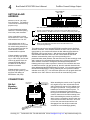
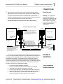
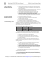
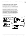
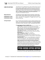
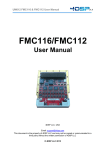
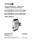
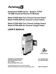
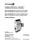
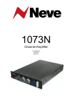
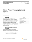
BusWorks® 900PB Series ProfiBus/RS485 Network I/O Modules Model 972PB-2004 Four Channel Current Output Model 972PB-2006 Six Channel Current Output Model 973PB-2004 Four Channel Voltage Output Model 973PB-2006 Six Channel Voltage Output USER’S MANUAL ACROMAG INCORPORATED 30765 South Wixom Road Wixom, MI 48393-2417 U.S.A. Copyright 2002, Acromag, Inc., Printed in the USA. Data and specifications are subject to change without notice. Tel: (248) 624-1541 Fax: (248) 624-9234 8500693E 2 BusWorks® 972/973PB User’s Manual ProfiBus Current/Voltage Output __________________________________________________________________ TABLE OF CONTENTS Symbols on equipment: ! Means Refer to User’s Manual (this manual) for additional information”. The information of this manual may change without notice. Acromag makes no warranty of any kind with regard to this material, including, but not limited to, the implied warranties of merchantability and fitness for a particular purpose. Further, Acromag assumes no responsibility for any errors that may appear in this manual and makes no commitment to update, or keep current, the information contained in this manual. No part of this manual may be copied or reproduced in any form without the prior written consent of Acromag, Inc. IMPORTANT SAFETY CONSIDERATIONS You must consider the possible negative effects of power, wiring, component, sensor, or software failure in the design of any type of control or monitoring system. This is very important where property loss or human life is involved. It is important that you perform satisfactory overall system design and it is agreed between you and Acromag, that this is your responsibility. GETTING STARTED MOUNTING AND DIMENSIONS……………………… CONTROLS & INDICATORS..………………………… ISOLATION BARRIERS..………………………………. SETTING SLAVE ADDRESS………………………….. CONNECTIONS…………………………………………. DIN-Rail Mounting And Removal……………... Network…………………………………………….. Power……………………………………………….. Analog Outputs…..………………………………. Earth Ground..……………………………………. TROUBLESHOOTING………………………………….. Tips For Building ProfiBus Networks..………. Top Four Common ProfiBus Problems………. Troubleshooting Tools………………………….. Using Connectors To Troubleshoot………….. Diagnostics Function……………………………. Diagnostics Table…………………………..……. CALIBRATION…………………………………………... 3 3 3 4 4 4 5 6 6 7 7 7 8 8 9 9 9 10 TECHNICAL REFERENCE KEY FEATURES………………………………………… HOW IT WORKS………….…………………………….. SPECIFICATIONS………………………………………. Model Numbers…………………………………… Analog Outputs………………....………………… General Specifications………………………….. Enclosure/Physical………………………………. Agency Approvals…..……………………………. Environmental…………………………………….. Communication Interface……………………….. Controls & Indicators……………………………. Module Specific Parameters…………………… Data Types………………………………………… 12 13 14 14 14 15 16 16 17 18 19 19 20 Windows® is a registered trademark of Microsoft Corporation. Profibus® is a registered trademark of ProfiBus Trade Organization. All trademarks are the property of their respective owners. _______________________________________________________________________________________ Acromag, Inc. Tel:248-624-1541 Fax:248-624-9234 Email:[email protected] http://www.acromag.com 3 TB3 MOUNTING AND DIMENSIONS TB3 BusWorks® 972/973PB User’s Manual ProfiBus Current/Voltage Output ___________________________________________________________________ Unit mounts to “T” type DIN rails (35mm, type EN50022). Acromag Units may be mounted sideby-side on 1-inch centers. I 5+ RTN I 4+ RTN I 3+ TB2 I 2+ 11 12 13 14 15 16 21 22 23 24 25 26 TB2 TB1 1.05 (26.7) WARNING: IEC Safety Standards may require that this device be mounted within an approved metal enclosure or sub-system, particularly for applications with exposure to voltages greater than or equal to 75VDC or 50VAC. ANALOG OUTPUTS RTN I 1+ RTN I 0+ RTN TB1 2.34 (59.4) ANALOG OUTPUTS RTN PROFIBUS PWR 3.75 (95.3) CL DC- SLAVE ADDRESS (HEX) DC+ LSD MSD 33 32 31 BUS 4.68 (118.9) RUN 3.90 (99.1) "T" RAIL DIN MOUNTING DIN EN 50022, 35mm 4.35 (110.5) NOTE: Dimensions Are INCHES (MILLIMETERS). MODEL 972/973PB-2006 ENCLOSURE DIMENSIONS DP SLAVE ADDRESS SWITCHES TB3 CONTROLS & INDICATORS SLA VE A D D RESS (H EX) TB3 LSD MSD 33 32 31 BUS DC+ RUN DC- Acromag RUN/PWR LED (GREEN) BUS STATUS LED (YELLOW) Green Run LED will stay ON if power is on and unit is OK, and will blink if unit fails. PWR PROFIBUS RTN I 5+ RTN I 4+ RTN TB2 11 12 13 14 15 16 I 3+ A N A LOG OU TPUTS RTN I 2+ RTN I 1+ RTN TB1 21 22 23 24 25 26 TB2 TB1 PWR 972/973PB ISOLATION DIAGRAM TB3 ISOLATION BARRIERS DC- DC+ LSD MSD 33 32 31 SLAVE ADDRESS (HEX) ANALOG OUTPUT AND LOGIC CIRCUIT PWR TB3 REMOVABLE (PLUG-IN TYPE) TERMINAL BLOCKS I 0+ A N A LOG OU TPUTS PROFIBUS CONNECTOR DB9 FEMALE Yellow BUS LED will turn ON if module is properly connected to the network and in data exchange mode. Dashed Lines denote isolation barriers. TRANSFORMER OPTICAL 5V SW The input circuit, network, and power circuit are isolated from each other for safety and noise immunity. 15V 11 12 13 14 15 16 RTN I 5+ RTN I 4+ I 3+ TB2 ANALOG OUTPUTS RTN I 2+ RTN I 1+ RTN I 0+ TB1 ANALOG OUTPUTS RTN NETWORK 5V 21 22 23 24 25 26 TB2 TB1 ANALOG OUTPUTS ANALOG OUTPUTS _______________________________________________________________________________________ Acromag, Inc. Tel:248-624-1541 Fax:248-624-9234 Email:[email protected] http://www.acromag.com 4 BusWorks® 972/973PB User’s Manual ProfiBus Current/Voltage Output __________________________________________________________________ HEX ADDRESS MSD LSD x16 x1 SETTING SLAVE ADDRESS TOP EDGE VIEW Address is set to 126 (7EH) from the factory. This address is reserved for commissioning purposes only. EF 0 1 2 EF 0 1 2 D 3 D 3 C 4 C 4 B 5 B 5 A9 76 A9 76 8 8 SET SWIT CHES T O A VALID SLAVE ADDRESS FROM 0 TO 125 (00H TO 7DH) Locate hexadecimal address switches in recessed opening next to the power terminals. 1. Choose a slave address from 0-125 and locate highest MSD number less than this address. Set MSD switch to this number's corresponding HEX digit. MSD x16 HEX LSD DEC x1 HEX 1 Use a screwdriver to rotate these switches to set a unique valid address from 0 to 125. 2 If the switches are set to a valid address from 0-125, then the switch setting determines the slave address and the Set Slave Address software command will be rejected. 0 0 0 0 16 1 1 1 32 2 2 2 48 3 3 3 64 4 4 4 80 5 5 5 96 6 6 6 112 128 144 160 176 192 208 224 240 7 8 9 A B C D E F 7 8 9 10 11 12 13 14 15 7 8 9 A B C D E F 2. Determine the DECimal remainder and set the LSD switch to its corresponding HEX digit. If these switches are instead set to 126 (7EH) upon powerup (or 126 to 254), the unit will retrieve its address from the internal EEPROM, which is modified via the Set Slave Address command. If these switches are set to 255 (FFH) upon power-up, this will return the address in EEPROM to 126 (7EH). The address stored in the internal EEPROM is modified via the Set Slave Address command. If the address switches are set to 126 (or 126 to 254) upon power-up, the module will retrieve the last address stored within its EEPROM (126 from the factory). With both the internal EEPROM and external switch addresses set to 126, the unit will await the Set Slave Address command after power-up, before proceeding to the parameterization state (address 126 cannot be used in data exchange mode and is reserved for commissioning purpose only). You must use the Set Slave Address command to change the internal (EEPROM) address following power-up in order to proceed. However, if the switches are set to an address less than 126 upon power-up, then the switches determine the slave address and the EEPROM setting is ignored. You can later restore the internal EEPROM setting to 126 by powering the unit up with the address switches set to 255 (FF). You would then power the unit up again with these switches set to 126 in order to return the unit to commissioning mode. CONNECTIONS PUSH DC- LSD MSD 33 32 31 SLAVE ADDRESS (HEX) DC+ 46 45 44 43 42 41 TB3 USE YOUR FINGER TO APPLY DOWNWARD PRESSURE HERE AS YOU LIFT AND TILT MODULE TO REMOVE IT FROM RAIL TB4 DIN-Rail Mounting & Removal MODULE REMOVAL FROM DIN RAIL PWR "T" TYPE DIN RAIL 11 12 13 14 15 16 TB2 TB1 Any Series 9XXPB ProfiBus Module 21 22 23 24 25 26 Remove Terminal Blocks On This Side To Provide Clearance PRY WITH SCREWDRIVER INSERTED IN SLOT HERE (DO NOT TWIST TO AVOID DAMAGING PLASTIC TAB) When attaching the module to the T-type DIN rail, angle the top of the unit towards the rail and locate the top groove of the adapter over the upper lip of the rail. Firmly push the unit towards the rail until it snaps into place. To remove, first separate the input terminal block(s) from the bottom side of the module to create a clearance to the DIN mounting area. Next, while holding the module in place from above, insert a screwdriver into the lower arm of the DIN rail connector and use it as a lever to force the connector down until the unit disengages from the rail (do not twist the screwdriver to avoid damaging plastic). PUSH SCREWDRIVER AS SHOWN TO TILT AND LIFT MODULE OFF RAIL _______________________________________________________________________________________ Acromag, Inc. Tel:248-624-1541 Fax:248-624-9234 Email:[email protected] http://www.acromag.com BusWorks® 972/973PB User’s Manual ProfiBus Current/Voltage Output ___________________________________________________________________ Siemens ProfiBus Connector CONNECTIONS 3 8 4 9 5 Network 7 R on off ProfiBus Cable (Violet) Grn off Green Wire = A Red Wire = B IN OUT Network Do not mix RS485 A & B connections. Green wire is A, red wire is B. You MUST terminate the network at both ends only. Termination resistors are integrated in the ProfiBus connector. When you switch termination ON, the out-going connections are disconnected from the network. Insul Shld on Strip Cable Similar to Shown AB 0.25 Red 2 6 1 DB9 (Male) Termination Switch 5 0.35 0.30 PVC Sheath Use ProfiBus cable per DIN 19245 and EN 50170. Use ProfiBus connectors similar to the one shown at left (Siemens version shown). Always use ProfiBus cable per DIN 19245 and EN 50170. When building cables, do not mix A & B connections. Green wire is A, Red wire is B. The connectors must have built-in inductors in order to operate at the higher baud rates. GSD Files: 972PB-2004 ACRO0769.GSD Ident_Number=0769H 972PB-2006 ACRO0768.GSD Ident_Number=0768H 973PB-2004 ACRO06FF.GSD Ident_Number=06FFH 973PB-2006 ACRO06FE.GSD Ident_Number=06FEH Network Length Use Type A ProfiBus cable per EN 50170. Keep line lengths less than the length indicated below for your transmission rate. For baud rates not shown, the lower length of the closest range end points apply (i.e. 100M at 3Mbps). Bus Segment Length Limit Per Baud Rate For Type A Bus Cable BAUD 9.6K 19.2K 93.75K 187.5K 500K 1.5M 12M Type A 1200M 1200M 1200M 1000M 400M 200M 100M Termination IMPORTANT: Do not connect earth ground to logic Ground (DB9 Pin 5). Earth Ground should connect to the cable Shield (common to DB9 Pin 1). Note that Acromag modules also support the optional RTS direction control signal at Pin 4. The network must be terminated at both ends only. Most ProfiBus connectors include a switch for termination as shown above. Note that this switch will also disconnect the outgoing network signal. _______________________________________________________________________________________ Acromag, Inc. Tel:248-624-1541 Fax:248-624-9234 Email:[email protected] http://www.acromag.com CONNECTIONS A network segment may contain up to 32 nodes without the use of a signal repeater. Transmission distance is up to 1200 meters per segment without a repeater. Termination must be placed at both ends of a network or network-segment. Example ProfiBus System Connections A cr om ag A cr om ag RUN RUN BUS PRO FI BUS BUS The total number of nodes and total distance may be extended by using signal repeater(s). The maximum number of modules possible is further limited by the address range from 0 to 125. PRO FI BUS Power on 31 of f NODE 32' BUS PRO FI BUS on of f NODE 2' START OF SEGMENT (TERMINATION ON) END OF NETWORK (TERMINATION ON) on of f NODE 32 NODE 1' of f 30 4 NODE 31 END OF SEGMENT (TERMINATION ON) NODE 5 SEGMENT 2 (UP TO 1200 METERS, UP TO 32 NODES PER SEGMENT) PROFIBUS MASTER PLUG-IN CARD INSTALLED IN PC. NETWORK LENGTH PER BAUD RATE w/ TYPE A PROFIBUS CABLE BAUD 9600bps 19.2Kbps 93.75Kbps 187.5Kbps 500Kbps 1.5Mbps 12Mbps LENGTH 1200M 1200M 1200M 1000M 400M 200M 100M START OF NETWORK (TERMINATION REQD) PROFIBUS MASTER - A HOST PC WITH PROFIBUS CARD INSTALLED AND RUNNING APPLICATION SOFTWARE. A cr om ag A cr om ag A cr om ag RUN RUN RUN BUS PRO FI BUS on BUS PRO FI BUS on on of f 1 of f 2 NODE 2 PROFIBUS RS485 NETWORK BUS PRO FI BUS of f NODE 1 3 NODE 3 NODE 4 SEGMENT 1 (UP TO 1200 METERS, UP TO 32 NODES PER SEGMENT) NOTE: THE PROFIBUS CONNECTORS SHOWN HAVE A TERMINATION NETWORK BUILT-IN. WITH TERMINATION ON, THE OUTGOING CABLE IS DISCONNECTED FROM NETWORK. SWITCH TERMINATION ON ONLY AT THE BEGINNING AND END OF A NETWORK OR NETWORK SEGMENT. Voltage Current 972PB-2006 16VDC 318mA 24VDC 190mA 36VDC 127mA 973PB-2006 16VDC 207mA 24VDC 135mA 36VDC 94mA Connect 16-36V DC to power terminals labeled DC+ & DC-. Observe proper polarity. For supply connections, use No. 14 AWG wires rated for at least 75C. CAUTION: Do not exceed 36VDC peak. OBSERVE PROPER POLARITY TB3 16 TO 36VDC + TB3 EARTH GROUND DC+ DC- PWR TIP: A recommended RS485 repeater for ProfiBus is the Siemens 6ES7 972-0AA010XA0. RUN BUS PRO FI BUS LSD MSD 33 32 31 Note: 12Mbps installations require a minimum cable length of 1M between stations. on 61 A cr om ag RUN RS485 SIGNAL REPEATER TERMINATION SWITCH Up to 125 slave modules may network together with a class 1 master using four repeaters (one repeater every 31 nodes). Address 0 is typically reserved for the class 1 master. A cr om ag INPUT POWER IS ISOLATED SLAVE ADDRESS (HEX) 6 BusWorks® 972/973PB User’s Manual ProfiBus Current/Voltage Output __________________________________________________________________ CAUTION: Risk of Electric Shock – More than one disconnect switch may be required to de-energize equipment before servicing. IMPORTANT – External Fuse: If unit is powered from a supply capable of delivering more than 1A to the unit, it is recommended that this current be limited via a high surge tolerant fuse rated for a maximum current of 1A or less (for example, see Bel Fuse MJS1). Analog Outputs CURRENT OUTPUT CONNECTIONS (972PB) SHIELDED CABLE Current outputs may drive up to 20.8mA into 500Ω. Voltage outputs may deliver up to 10V into 1KΩ (10mA). CURRENT OUT LOAD (UP TO 550 OHMS) RL EARTH GROUND I 0+ RTN I 1+ RTN I 2+ RTN ANALOG OUTPUTS + TB1 VOLTAGE OUTPUT CONNECTIONS (973PB) SHIELDED CABLE CHANNEL 1 OF 6 VOLTAGE OUT LOAD (UP TO 10mA) TB1 + RL EARTH GROUND V 0+ RTN V 1+ RTN V 2+ RTN ANALOG OUTPUTS Outputs are not isolated channel-to-channel and share a common return (RTN). TB1 I 16 15 14 13 12 11 CHANNEL 1 OF 6 16 15 14 13 12 11 Output is DC Current (972PB) or DC Voltage (973PB). Connect analog outputs as shown below according to your model. TB1 _______________________________________________________________________________________ Acromag, Inc. Tel:248-624-1541 Fax:248-624-9234 Email:[email protected] http://www.acromag.com 7 BusWorks® 972/973PB User’s Manual ProfiBus Current/Voltage Output ___________________________________________________________________ CONNECTIONS Connect Earth Ground as shown in the connection drawings above. Additionally, ground the ProfiBus cable as shown in the drawing below. Earth Ground The ground connections noted are recommended for best results. If sensors are already grounded, use caution and avoid making additional ground connections which could create ground loops. Warning: To comply with safety and performance standards, use shielded cable and connect earth ground as noted. Failure to use good wiring and grounding practices may be unsafe and hurt performance. The plastic module housing does not require earth ground. PROFIBUS WIRING AND GROUND PROFIBUS CONNECTOR GROUNDING: 1. Always connect the cable shield to earth ground at both ends as shown. 2. If the field device does not include an earth ground screw, it may be necessary to strip the cable insulation near the field device and clamp the cable shield to a local grounding bar or surface as shown. PROFIBUS FIELD DEVICE THE SHIELD IS COMMON TO THE HOUSING (FOR METAL ENCLOSURES). OUT GROUND CLAMP ACROMAG MODULES: The metal shroud of the DB9 ProfiBus connector on Acromag modules is common to pin 1 of the DB9 connector (SHIELD). This is also common to the cable shield which must be earth grounded. Acromag modules are enclosed in plastic and do not provide a dedicated earth ground screw. As such, a local earth ground connection to the cable shield must be made as shown above. R on off CABLE SHIELD INP NOTE: If a potential difference exists between earth grounding points, an equalization current can flow through the cable shield when connected at both ends. In this case, it may be necessary to install an additional potential equalization line between field locations to minimize this current as shown here. CABLE SHIELD EQUIPOTENTIAL BONDING STRIP (IF NECESSARY--SEE NOTE) PROFIBUS CABLE The module routinely performs internal diagnostics following power-up or reset. During this period, the green “Run” LED will flash for a moment. If the diagnostics complete OK, the “Run” LED will stop flashing after a few seconds and remain ON. This indicates the unit is operating normally. Once the unit has passed through the initialization, parameterization, and configuration states, and is in data exchange mode, the yellow BUS LED will be ON. If the BUS LED is OFF and the unit is connected to the network, then this is indicative of an initialization problem. EARTH GROUND SCREW ON EQUIPMENT (WHEN AVAILABLE) Follow the ProfiBus installation guidelines. Use the recommended cable and connectors of the standard. Verify that none of the wires are broken or shorted. Don’t mix the A & B lines. Use green wire for A and red wire for B. Do not exceed the recommended segment length for the baud rate. Make sure that there are no more than 32 RS-485 devices per segment (including the master device and the repeater). GROUND CLAMP THE SHIELD IS COMMON TO THE HOUSING (FOR METAL ENCLOSURES). Use ProfiBus cable per DIN 19245 and EN 50170. Use only approved cables with braided shields of density greater than 80%. Green Wire = A Red Wire = B AB Shld Red R on off EARTH GROUND SCREW ON EQUIPMENT (WHEN AVAILABLE) Grn PROFIBUS FIELD DEVICE Insul PROFIBUS CONNECTOR PVC Sheath TROUBLESHOOTING Tips For Building ProfiBus Networks _______________________________________________________________________________________ Acromag, Inc. Tel:248-624-1541 Fax:248-624-9234 Email:[email protected] http://www.acromag.com 8 BusWorks® 972/973PB User’s Manual ProfiBus Current/Voltage Output __________________________________________________________________ Tips For Building ProfiBus Networks Top Four Common ProfiBus Problems Troubleshooting Tools Check for proper termination of all copper-wire network segments (an RS-485 segment must have a termination resistor at both ends of the segment only). All activated terminations must be powered all the time. If this is not possible, then consider using an active-termination box. Check whether the station address is set to the correct value. If your network connects between buildings or runs through hazardous environments, consider the use of fiber-optics. Avoid drop lines and keep their length within the specified maximum. For T-drops, consider using repeaters and active-bus terminations. 1. Incorrect slave address set at the slave. 2. ProfiBus connector between the master and slave has its termination switch turned ON. 3. Incorrect module configuration sent to slave. 4. Configuration is based on outdated GSD file information. There are several models of handheld devices on the market that simplify the installation and troubleshooting of ProfiBus networks. The more sophisticated units include LCD displays that read out errors directly. Two of these of these devices are referenced below: Hand-Held ProfiBus Network Maintenance Tools Manufacturer Part Number Special Features Siemens BT 200 Primarily a Cable Tester Comsoft NetTest II Set Includes DP Mono-Master 4000-7-06C-J Functionality In general, these devices can be used to check the network wiring before devices are connected to the bus and are often used to indicate: Whether the A and B lines have been switched. Whether a short exists between the A & B lines and shield. The occurrence of a wire-break in the A or B line, or shield line. Improper termination. These devices can also be used to check the RS-485 interface of ProfiBus devices after they have been connected. They may include the following functions: The ability to create a list of all stations connected to a network (useful for identifying missing or “offline” devices). Test individual stations and help identify duplicate addresses. Measure the distance along a network segment to verify whether it complies with the Profibus requirements for distance and data rate. Detect signal reflections along the network, useful for locating bus line interruptions and discontinuities. Acromag strongly suggests the use of these tools for building and maintaining ProfiBus networks. Note that Profichip also offers a Profibus connector (PA003100) that includes 4 network diagnostic LED’s that may be helpful in trouble-shooting your network (see table below). _______________________________________________________________________________________ Acromag, Inc. Tel:248-624-1541 Fax:248-624-9234 Email:[email protected] http://www.acromag.com BusWorks® 972/973PB User’s Manual ProfiBus Current/Voltage Output ___________________________________________________________________ The standard 9-pin ProfiBus connectors with integrated termination resistors are also helpful in troubleshooting segments of the network. In most of these connectors, when the termination resistors are switched ON, the outgoing portion of the connector is disconnected. As such, you can selectively disable segments of the network until you find the branch that is causing the problem. For example, if your handheld unit is connected to the beginning of a network and indicates a wire break, you can selectively switch off portions of the network and recheck your handheld unit to help pin point the portion of the network that is causing the problem. Below are some ProfiBus connectors that we recommend: Preferred Bus Connectors Mfg Part Number Siemens 6ES7972-0BA12-0XA0 Siemens 6ES7972-0BB12-0XA0 Profichip PA003100 Cannot communicate. Yellow BUS LED turned OFF. Continuous flashing green RUN LED. Many Communication Errors. Using Connectors To Troubleshoot Special Features Switchable termination. Adds PB interface (piggy-back DB9 for diagnostic connection). Adds PB interface & 4 diagnostic LED’s for trouble-shooting. ProfiBus includes a rich diagnostic function that can be used to troubleshoot ProfiBus devices. This function contains 6 bytes of standard diagnostic information, plus up to an additional 238 bytes of device specific diagnostic information. Most configuration tools support this command and can read the diagnostic information from the Profibus device. SYMPTOM Yellow BUS LED does not light. 9 POSSIBLE CAUSE Initialization Problem. LED ON if module in data exchange state. Both internal EEPROM and external address switches are set to an address of 126. Power ON at module and/or converter? Is address correct? Is the termination switch of the Profibus connector at the prior node turned on? Communication Halted. Internal firmware problem. Missing Termination Resistors? Is baud rate too high for distance? POSSIBLE FIX Check Station Address. Is GSD file correct? Check for wiring error. Module is awaiting Set Slave Address command in order to complete initialization. Alternately, set switches from 0-125 and re-power. Check power. Is green RUN LED ON? Check address settings. Switch Termination on only at the ends of the network. With termination switch on, the outgoing connections are disconnected from the network chain. Cycle power to reset unit. Investigate grounding. Return the module for service. Termination resistors must be placed only at both ends of a network or segment. Maximum distance is limited below 1200 meters as baud rate is increased above 93.75Kbps (see Table). Diagnostics Function Diagnostics Table If your problem still exists after checking your wiring and reviewing this information, or if other evidence points to another problem with the unit, an effective and convenient fault diagnosis method is to exchange the module with a known good unit. Acromag’s Application Engineers can provide further technical assistance if required. Complete repair services are also available from Acromag. _______________________________________________________________________________________ Acromag, Inc. Tel:248-624-1541 Fax:248-624-9234 Email:[email protected] http://www.acromag.com 10 BusWorks® 972/973PB User’s Manual ProfiBus Current/Voltage Output __________________________________________________________________ CALIBRATION The Series 972/973PB output modules are calibrated using a single base output range with fixed calibration endpoints. The calibration of the module’s sub-ranges are interpolated based on these results. Prior to calibration, the 972PB models must have the 4-20mA output range selected, and the 973PB must have the 0-10V output range selected. Calibration is then performed by adjusting the output signal level until its measured value precisely matches the low or high calibration range endpoint indicated. With the output level precisely adjusted to the Calibration LOW or HIGH range endpoint signal, the module is triggered to store the output channel’s raw DAC count by toggling the corresponding channel’s Cal HIGH (upper byte) or Cal LOW (lower byte) calibration register. The following table gives the calibration values for the base output range of these models. Your success in recalibrating the output will strongly depend upon the accuracy and precision of your measurement system with respect to calibrating the base range endpoints. IMPORTANT: This module has already been calibrated at the factory and recalibration is not normally required, except as necessary to correct for long term component aging, or to satisfy your company’s maintenance requirements. Do not attempt to recalibrate this module unless absolutely required, as miscalibration will negatively affect the module’s performance. Cal LOW (Zero) Cal HIGH (Full-Scale) Model Range Signal ~Write % Signal ~Write % 972PB 4-20mA 4.000mA 4000 20.000mA 20000 973PB 0-10V 0.000V 0 10.000V 20000 Notes: 1. Output values are written via 16-bit signed integer values with resolution of 0.005%/lsb. 20000 is used to represent 100%. For example, -100%, 0% and +100% are represented by decimal values –20000, 0, and 20000, respectively. The full range is –163.84% (-32768 decimal) to +163.835% (+32767 decimal). 2. The “Write %” values noted above are the ideal values written to the output word of the channel and may only approximate the value required to produce the Cal LOW and Cal HIGH endpoint signals. During calibration, you need to adjust these values as required to precisely reproduce the endpoint signals. 3. Calibration of the 0-20mA & 0-1mA, and 0-5V & 0-1V subranges are internally interpolated from the resultant calibration of the base range noted in the table above for each model. Additionally, since resolution is degraded for the sub-ranges, it is very important that high accuracy be ensured for the primary base calibration when making output adjustments and measurements. These models have two output configuration definitions in their GSD files: one for normal output operation (4 or 6 output words according to the number of output channels), and another for accomplishing output calibration (with 8 or 12 output words according to the number of output channels). The normal data exchange definition supports 4 or 6 output words (8 or 12 output bytes representing your programmed values). A second calibration definition supports 4 or 6 output words, plus an additional 4 or 6 output words that represent the channel calibration words. Your Master software allows you to choose which mode the slave will assume— normal Output Mode or Output Calibration Mode. The method used to transfer information between the master and slave will vary widely between systems. The steps below represent the minimum steps necessary to accomplish software calibration. If you choose to perform output calibration and select the Calibration Mode, the master will download the 4/4 or 6/6 word configuration during the startup sequence, and the module may then be calibrated as follows: _______________________________________________________________________________________ Acromag, Inc. Tel:248-624-1541 Fax:248-624-9234 Email:[email protected] http://www.acromag.com BusWorks® 972/973PB User’s Manual ProfiBus Current/Voltage Output ___________________________________________________________________ IMPORTANT: For best results, you must measure the output signal via an external current or volt meter that is at least as accurate as the module itself (better than ±0.1% of span). Always calibrate the low value before the high value and allow the module to warm up a few minutes prior to calibration. 11 CALIBRATION General Calibration Procedure: 1. With your master software, select the “Calibration Mode” from the GSD file when setting up the master to communicate with the module. 2. With user parameterization bytes 1-6 (or 1-4), set the base range for each channel to be calibrated. Select 4-20mA for 972PB models, or 010V for 973PB models. 3. Write the zero calibration % value to the output to be calibrated and adjust this value as necessary to precisely reproduce the Cal LOW (zero) signal (see table of prior page). Allow the output to settle a few seconds. 4. Write FFH into the low-order byte of the channel’s calibration word several times to ensure transmission. In Output Calibration Mode, the module will automatically calibrate the channel’s zero value when FFH is detected in the low-order byte. Then write 00H into the low-order byte to complete zero calibration. 5. Write the full-scale calibration % value to the output to be calibrated and adjust this value as necessary to precisely reproduce the Cal HIGH (fullscale) signal (see table of prior page). Allow the output to settle a few seconds. 6. Write FFH into the high-order byte of the channel’s calibration word several times to ensure transmission. In Output Calibration Mode, the module will automatically calibrate the channel’s full-scale value when FFH is detected in the high-order byte. Then write 00H into the highorder byte to complete full-scale calibration. 7. Repeat steps 3-6 for each output channel to be calibrated. 8. When finished calibrating, use the master software to return the module to the normal “Output Mode” to prevent miscalibration. With user parameter bytes 1-6 (or 1-4), select the range required for your application. You may then check the calibration of the alternate range(s). Note that the alternate ranges are calibrated by interpolating their calibration endpoints from those of the base range. After completing calibration, the module should be reconfigured as required and placed in the normal Output Mode configuration (output configuration is 4 or 6 output words only). In general, your software allows you to select the normal “Output Mode” configuration, and the slave will then be taken off-line by the master and reconfigured. If reconfiguration is successful, the slave module will pass to the data exchange state with a normal Output Mode configuration. _______________________________________________________________________________________ Acromag, Inc. Tel:248-624-1541 Fax:248-624-9234 Email:[email protected] http://www.acromag.com 12 BusWorks® 972/973PB User’s Manual ProfiBus Current/Voltage Output __________________________________________________________________ TECHNICAL REFERENCE KEY FEATURES PTO Certified - Unit certified by the ProfiBus Trade Organization. Safety Agency Approvals – CE, UL, & cUL listed, plus Class 1; Division 2; Groups A, B, C, D approvals. Fully Independent Slave w/ Direct I/O Connection – This selfcontained unit does not require special bus couplers, power supplies, or a rack mount to operate. Plug-In Terminal Blocks & DIN-Rail Mount - Make mounting, removal, and replacement easy. Industry Standard ASIC – Uses Siemens SPC3 intelligent ASIC to talk ProfiBus. Isolated RS485/ProfiBus Network Interface – Highly immune to noise and can operate over long distances. Allows many modules to network together. Flexible Process Current Output (972PB) – Generates up to 6 process current signals in 3 ranges. Flexible DC Voltage Output (973PB) – Generates up to 6 DC voltage signals in 3 ranges. Selected Ranges May Vary Channel-to-Channel – Multiple channels may have different ranges configured. Auto-Baud Rate Detection – The baud rate is set automatically. High-Speed Data Rates – Half-duplex RS485 up to 12M baud. Includes RTS Support – ProfiBus interface includes the optional RTS (Request-To-Send) direction control. Precise High-Resolution D/A Conversion – Modules use high resolution (12-bit), low noise, digital-to-analog conversion for high accuracy and reliability. Nonvolatile Reprogrammable Memory – Allows the functionality of this device to be reliably reprogrammed thousands of times. Fully Isolated – Output channels (as a group), network, and power are all isolated from each other for safety and increased noise immunity. LED Indicators – A green LED indicates power. A yellow bus status LED indicates proper network connection and unit in data exchange mode. Watchdog Timer Built-In – Standard for the ASIC and operates in the data exchange mode if communication with the master is lost. Self-Diagnostics & Diagnostic Watchdog - For easy maintenance and troubleshooting. Includes a hardware watchdog timer built into the microcontroller that causes it to initiate a self reset if the controller ever “locks up” or fails to return from an operation in a timely manner. Wide-Range DC-Power - Diode-coupled for use with redundant supplies, and/or battery back-up. Hardened For Harsh Environments - For protection from RFI, EMI, ESD, EFT, & surges. Has low radiated emissions per CE requirements. Wide Ambient Operation – Reliable over a wide temperature range. _______________________________________________________________________________________ Acromag, Inc. Tel:248-624-1541 Fax:248-624-9234 Email:[email protected] http://www.acromag.com BusWorks® 972/973PB User’s Manual ProfiBus Current/Voltage Output ___________________________________________________________________ These transmitters will drive up to six analog current outputs (972PB), or six analog voltage outputs (973PB), and provide an isolated ProfiBus network interface for configuration and control of the outputs. The ProfiBus protocol is implemented via the industry-standard SPC3 ASIC from Siemens. The ASIC transfers network data to the microcontroller and automatically provides a response to the bus. The ASIC communicates with the network via an optically isolated RS485 transceiver. This ASIC acts like a RAM or UART chip to the internal microcontroller and completely handles the requirements of the ProfiBus protocol. The microcontroller completes the output transfer function according to the output type/range per its embedded program, and sends output values to two, 12-bit, quad-output DAC’s (Digital-to-Analog Converters). The corresponding DAC output voltages are sent to individual voltage-to-current converter circuits (972PB), or to non-inverting output amplifiers (973PB). Output configuration and calibration parameters are stored in non-volatile memory integrated within the microcontroller. A factory program port allows the microcontroller to be reprogrammed in circuit. A wide input switching regulator (isolated flyback) provides isolated power to the output circuit and the RS485 port. A second switcher converts the 15V output supply to a 5V logic supply. Refer to the simplified schematic below to gain a better understanding of the circuit. HOW IT WORKS 972/973PB SIMPLIFIED SCHEMATIC PWR LED OUTPUT CHANNEL 1 OF 6 (Typical) 13 ISOLATED RS485 BUS LED +5V +5V RTS OUT+ V-TO-I CONVERTER or RTN 12-bit DAC VOLTAGE AMPLIFIER PROFIBUS SPC3 SLAVE ASIC MICRO CONTROLLER RS485 PROFIBUS TRANSCEIVER 4 DB9 SHLD 4 N E T W O R K ADDRESS BUFFER EF 0 1 2 D 3 C 4 B 5 A9 76 8 OUTPUT CHANNEL 6 OF 6 OUT+ ISOLATED INPUT POWER V-TO-I CONVERTER or RTN EF 0 1 2 D 3 C 4 B 5 A9 76 8 VOLTAGE AMPLIFIER 12-bit DAC 16-36VDC ISOLATED SECONDARIES NETWORK POWER 5V OUTPUT/LOGIC +15V POWER SWITCHER +5V ISOLATED FLYBACK SWITCHER DC+ DC- P O W E R -0.7V _______________________________________________________________________________________ Acromag, Inc. Tel:248-624-1541 Fax:248-624-9234 Email:[email protected] http://www.acromag.com 14 BusWorks® 972/973PB User’s Manual ProfiBus Current/Voltage Output __________________________________________________________________ SPECIFICATIONS These DIN-rail mount, ProfiBus DP slave, output modules will drive up to six process current, or voltage signals, according to the model, and provide an isolated RS485/ProfiBus network interface for configuration and control of the outputs. Units are DC-powered and include reverse polarity protection. Outputs share a common return connection and are not isolated channel-tochannel. Outputs (as a group), network, and power are isolated from each other. Non-volatile reprogrammable memory in the module stores configuration and calibration information. Model Numbers The ProfiBus model prefix “900” denotes the Series 900. The “PB” suffix denotes ProfiBus. Select 972MB for current output, and 973PB for voltage output. The four digit suffix of this model number represents the following options, respectively: “2” = ProfiBus DP; “0” = Default; “04” or “06” = 4 or 6 channels, respectively. 972PB-2004 (4x Current) 972PB-2006 (6x Current) 973PB-2004 (4x Voltage) 973PB-2006 (6x Voltage) Analog Outputs Four or six analog output channels for current or voltage according to model number. The unit must be wired and configured for the intended output type and range (see Connections Section for details). The following paragraphs summarize this model’s output types, ranges, and applicable specifications. Current Output Specifications (972PB Only): Output Ranges: Select 0-20mA DC, 4-20mA DC, or 0-1mA DC. The 0-20mA and 0-1mA ranges are sub-ranges of the 4-20mA range. Note: The 0-20mA and 0-1mA output ranges may not precisely go to the 0mA endpoint. The 0-20mA range will typically approach 0mA within 0.1% of span. Do not use 0 as a calibration endpoint. Output Maximum Current: ~20.8mA typical (DAC count ~3758). Output Accuracy: See Resolution & Accuracy Table under General Specifications. Output Compliance: 12V Minimum, 13V Typical. Output Load Resistance Range: 0 to 625, typical. Response Time: 11ms typical into 500, for measurement to reach 98% of the final value in response to a step command. Actual response time will vary with load. Output Resolution: 12 bits, or 1 part in 4096 based on a theoretical 22.67mA over-range value. This is 5.535uA/bit (22.67mA/4096bits). Note the over-range DAC count is internally limited to approximately 3758, or 20.8mA. See below for effective resolution calculations. DAC Count (Current): Internal DAC count can be approximated by multiplying the output current by 180680. The resultant value (rounded) can be used to calculate the effective resolution and to approximate the required output register program value (see below). The over-range DAC count is internally limited to approximately 3758, or 20.8mA. Internal DAC Count Versus Current Output Range Range DAC 0% DAC 100% DAC Span 0-1mA 0 181 181 4-20mA 723 3614 2891 0-20mA 0 3614 3614 The effective resolution is 1 part in the DAC Span. The resolution and accuracy for the 0-1mA range is significantly less than the other ranges. _______________________________________________________________________________________ Acromag, Inc. Tel:248-624-1541 Fax:248-624-9234 Email:[email protected] http://www.acromag.com BusWorks® 972/973PB User’s Manual ProfiBus Current/Voltage Output ___________________________________________________________________ Register Program Value: Output values use integers with 20000 representing 100%. The required output register program value can be approximated using the DAC values shown above via the formula: Register Value = 20000 * (DAC Count – DAC 0%)/DAC Span. Ideal Current Output Register Program Value Output Current Range 0mA 1mA 4mA 12mA 0-1mA 0 20000 ----4-20mA ----0 10000 0-20mA 0 1000 4000 12000 15 Analog Outputs 20mA --20000 20000 Voltage Output Specifications (973PB Only): Output Range: Select 0-10V DC, 0-5V DC, or 0-1V DC. Ranges are sub-ranges of nominal 0-11.3V design limit (which includes approximately 13% of over-range). Output Maximum Voltage: 11.3V, typical. Output Accuracy: See Resolution and Accuracy Table under General Specifications. Output Current: 0-10mA DC maximum. Output Impedance: 1. Output Short Circuit Protection: Included Response Time: 110us rise time typical, 150us fall time typical, unloaded, for output to reach 98% of the final value in response to a step command. Actual response time will vary with load. Output Resolution: 1 part in 4046 based on 11.368V full-scale, or 2.81mV/bit (11.368V/4046bits). DAC Count (Voltage): The internal DAC count can be calculated by multiplying 355.96 by the sum of the output voltage and 0.1393. The resultant value (rounded) can be used to calculate the effective resolution and to approximate the required output register program value (see below). Note the effective resolution is 1 part in the DAC Span. Internal DAC Count Versus Voltage Output Range Range DAC 0% DAC 100% DAC Span 0-1V 50 406 356 0-5V 50 1829 1779 0-10V 50 3609 3559 Register Program Value: Output values use integers with 20000 representing 100%. The required output register program value can be approximated using the DAC values shown above via the following formula: Register Value = 20000 * (DAC Count – DAC 0%)/DAC Span. Ideal Voltage Output Register Program Value Output Voltage Range 0V 1V 2.5V 5V 0-1V 0 20000 ----0-5V 0 4000 10000 20000 0-10V 0 2000 5000 10000 10V ----20000 Accuracy: Outputs are accurate to better than 0.1% of output span, typical, for 4-20mA, 0-20mA, 0-10V, and 0-5V ranges (see table below). This includes the effects of repeatability, terminal point conformity, and linearization. General Specifications _______________________________________________________________________________________ Acromag, Inc. Tel:248-624-1541 Fax:248-624-9234 Email:[email protected] http://www.acromag.com 16 BusWorks® 972/973PB User’s Manual ProfiBus Current/Voltage Output __________________________________________________________________ General Specifications Ambient Temperature Effect: Better than ±.005% of output span per C (50ppm/C), or 1.0uV/C, whichever is greater. Digital-to-Analog Converter: Burr-Brown/Texas Instruments DAC7615, 12-bit. Monotonic to 12 bits. Integral Non-Linearity: 0.1% of span or 2LSB typical, whichever is larger, for spans equal to or greater than 16mA (972PB), or 5V (973PB). Analog Output Range Resolution & Accuracy Calibrated Output Range Effective Resolution Model 972PB-2004 or 972PB-2006 0 to 20mA DC .028%, 1/3614 4 to 20mA DC .035%, 1/2891 0 to 1mA DC .552%, 1/181 Model 973PB-2004 or 973PB-2006 0-10V DC .028%, 1/3559 0-5V DC .056%, 1/1779 0-1V DC .281%, 1/356 Inaccuracy as a Percent-of-Span 0.1% span (0.02mA) 0.1% span (0.02mA) 1.6% span (0.016mA) 0.1% span (10mV) 0.1% span (5mV) 0.8% span (8mV) Note (0-1mA & 0-1V ranges only): Due to the possible inability of the output to precisely adjust to the ideal range endpoints as a result of the low resolution for the 0-1mA & 0-1V ranges, effective inaccuracy may be as high as 2.2% & 1.1% respectively for these sub-ranges. Enclosure and Physical Dimensions: 1.05 inches wide, 4.68 inches tall, 4.35 inches deep. Refer to the dimensions drawing at the front of this manual. DIN Rail Mount: Type EN50022; “T” rail (35mm). I/O Connectors: Removable plug-in type terminal blocks rated for 15A/300V; AWG #12-24 stranded or solid copper wire. Network Connector: 9-pin D-Sub connector (female) with metal housing and 4-40 jack screw support. D-Sub Pin 1 2 3 4 5 6 7 8 9 Signal SHLD NC A RTS GND +5V NC B NC Description Shield (Connect to Earth Ground) No Connection Data A (TxD/RxD+) Request To Send RS485 Logic Ground +5V No Connection Data B (TxD/RxD-) No Connection Case Material: Self-extinguishing NYLON type 6.6 polyamide thermoplastic UL94 V-2, color beige; general purpose NEMA Type 1 enclosure. Printed Circuit Boards: Military grade FR-4 epoxy glass. Shipping Weight: 1 pound (0.45 Kg) packed. Agency Approvals ProfiBus Trade Organization (PTO): Certified. Safety Approvals: CE marked (EMC Directive 89/336/EEC); UL Listed (UL508, UL1604); cUL Listed (Canada Standard C22.2, No. 142M1987 & 213-M1987); Hazardous Locations: Class 1; Division 2; Groups A, B, C, and D. _______________________________________________________________________________________ Acromag, Inc. Tel:248-624-1541 Fax:248-624-9234 Email:[email protected] http://www.acromag.com BusWorks® 972/973PB User’s Manual ProfiBus Current/Voltage Output ___________________________________________________________________ Operating Temperature: 972PB: -25C to +60C (-13F to +140F); 973PB: -25C to +70C (-13F to +158F). Storage Temperature: -40C to +85C (-40F to +185F). Relative Humidity: 5 to 95%, non-condensing. Power Requirements: 16-36V DC SELV (Safety Extra Low Voltage). Observe proper polarity. Current draw will decrease up to 10% as the baud rate is increased to 12MB. Data below is at 9600 baud with current outputs (972PB) set to 20mA, and voltage outputs (973PB) set to 10V across 1KΩ (10mA). Power Supply 16V 24V 36V 972PB-2004 Current Typical/Maximum 204mA/224mA 132mA/145mA 92mA/101mA 972PB-2006 Current Typical/Maximum 289mA/318mA 173mA/190mA 115mA/127mA Power Supply 16V 24V 36V 973PB-2004 Current Typical/Maximum 154mA/169mA 103mA/113mA 73mA/80mA 973PB-2006 Current Typical/Maximum 188mA/207mA 123mA/135mA 85mA/94mA CAUTION: Risk of Electric Shock – More than one disconnect switch may be required to de-energize equipment before servicing. Power Supply Effect: Volts: Less than 0.001% of output span change per volt for rated power supply variations. 60/120 Hz Ripple: Less than 0.01% of output span per volt peak-topeak of power supply ripple. Isolation: Output channels (as a group), power, and network circuits are isolated from each other for common-mode voltages up to 250VAC, or 354V DC off DC power ground, on a continuous basis (will withstand 1500VAC dielectric strength test for one minute without breakdown). Complies with test requirements of ANSI/ISA-82.01-1988 for voltage rating specified. Installation Category: Designed to operate in an Installation in a Pollution Degree 2 environment with an Installation Category (over-voltage category) II rating. Electromagnetic Interference Immunity (EMI): Output shift has been demonstrated at less than 0.25% of output span for interference from switching solenoids, commutator motors, and drill motors. Electromagnetic Compatibility (EMC) Minimum Immunity Per European Norm EN50082-1: Electrostatic Discharge (ESD) Immunity: 4KV direct contact and 8KV air-discharge to the enclosure port per EN61000-4-2. Radiated Field Immunity (RFI): 10V/M, 80 to 1000MHz AM and 900MHz keyed carrier, per EN61000-4-3 and ENV50204. Electrical Fast Transient Immunity (EFT): 2KV to power, and 1KV to signal I/O per EN61000-4-4. Conducted RF Immunity (CRFI): 10Vrms, 150KHz to 80MHz, per EN61000-4-6. Surge Immunity: 0.5KV per EN61000-4-5. Emissions Per European Norm EN50081-1: Radiated Frequency Emissions: 30 to 1000MHz per EN55022 Class A 17 Environmental CAUTION: Do not exceed 36VDC peak, to avoid damage to the module. External Fuse: Select a high surge tolerant fuse rated for 1A or less to protect unit. Note that input channels are not isolated channel-tochannel, except for small common-mode variations less than ±4V peak. These limits represent the minimum requirements of the standard, but product has typically been tested to comply with higher standards in some cases. _______________________________________________________________________________________ Acromag, Inc. Tel:248-624-1541 Fax:248-624-9234 Email:[email protected] http://www.acromag.com 18 BusWorks® 972/973PB User’s Manual ProfiBus Current/Voltage Output __________________________________________________________________ Environmental WARNING: This is a Class A product. In a domestic environment, this product may cause radio interference in which the user may be required to take adequate measures. IMPORTANT: Power, input, and output (I/O) wiring must be in accordance with Class I, Division 2 wiring methods Article 501-4(b) of the National Electrical Code, NFPA 70 for installations in the U.S., or as specified in section 18-1J2 of the Canadian Electrical Code for installations within Canada and in accordance with the authority having jurisdiction. This equipment is suitable for use in Class I, Division 2, Groups A, B, C, and D, or non-hazardous locations only. WARNING – EXPLOSION HAZARD – Substitution of components may impair suitability for Class I, Division 2. WARNING – EXPLOSION HAZARD – Do not disconnect equipment unless power has been switched off or the area is known to be non-hazardous. Communication Interface Interface Standard: 3-wire RS-485 multi-drop, half-duplex (D, D-bar, and Common), asynchronous. Command/Response Protocol: Standard ProfiBus DP (Master/Slave) protocol per European Norm EN50170. Baud Rate: Supported baud rates are 9600, 19.2K, 45.45K, 93.75K, 187.5K, 500K, 1.5M, 3M, 6M, and 12M bits per second, auto-detected. Maximum transmission length is dependent on baud rate selection (range is up to 1200M at 9600bps, or up to 100M at 12Mbps). Refer to the following table for maximum transmission distances at supported baud rates using recommended type A (<30pF/M), or alternately type B (<60pF/M) bus wire (see EN50170): Baud Rate 9600 bps 19.2K bps ≤ 93.75K bps 187.5K bps 500K bps 1.5M bps ≤ 12M bps NETWORK LENGTH Type A Type B 1200M 1200M 1200M 1200M 1200M 1200M 1000M 600M 400M 200M 200M NA 100M NA Address: Set via two rotary hexadecimal switches adjacent to the power terminals, or alternately via the Set Slave Address command. Valid setting is 0-125 (7 bits). Address 126 (7EH) is the default factory address and is reserved for commissioning purposes only. Address 127 (7FH) is reserved by the software as a global address for broadcast messages. If the address switches are set to 126 upon power-up (or 126-254), then the unit will retrieve its address from its internal EEPROM rather than the switches. The internal EEPROM setting is modified via the Set Slave Address command. Powering up with switches set to 255 (FFH) will cause the internal EEPROM setting to revert back to 126 (7EH), which may be used to recommission the module. If both the internal EEPROM address and the switches are set to 126 upon power-up (this is the initial state from the factory), the module will await the Set Slave Address command before completing initialization and assuming the data exchange mode. _______________________________________________________________________________________ Acromag, Inc. Tel:248-624-1541 Fax:248-624-9234 Email:[email protected] http://www.acromag.com BusWorks® 972/973PB User’s Manual ProfiBus Current/Voltage Output ___________________________________________________________________ 19 IMPORTANT (Address Setting): The internal EEPROM address setting and external switch setting is 126 from the factory. As such, the module will await the Set Slave Address command following power-up and will not proceed to exchange data, unless the external switches are instead set to an address from 0-125, or the internal setting is changed to an address from 0-125 via the Set Slave Address command. Parity/Stop Bits: Even parity with one stop bit. Communication Distance: Up to 1200 meters without a repeater. Maximum Message Size: Up to 32 bytes recommended, extendable up to 244 bytes of data/node/message, plus 11 bytes of overhead (frame). ProfiBus Character: 11 bits (1 start bit + 8 data bits + 1 even parity bit + 1 stop bit). Applies to all bytes, including frame bytes. Ident_Number: 0769H (972PB-2004), 0768H (072PB-2006), 06FFH (973PB-2004), 06FEH (973PB-2006). GSD File: 972PB-2004: ACRO0769.GSD; 972PB-2006: ACRO0768.GSD; 973PB-2004: ACRO06FF.GSD; 973PB-2006: ACRO06FE.GSD. Bus Idle State: “1” (a start bit causes line to go to “0”). An idle state of at least 33 Tbits (sync-time) must be provided between messages. Note: 1Tbit at 12Mbaud = 1/12000000bit/sec = 83nsec. Network Capacity: Multi-drop up to 31 modules, plus a host, without a repeater. Up to 125 modules plus a host if four repeaters are used (one for every 31 nodes). Network Termination: Use 220Ω “A” to “B”, plus 390Ω “A” to GND, and 390Ω “B” to +5V. Use ±2%, 0.25W resistors. Communication Interface LED Indicators: Run (Green) - Constant ON indicates power applied and unit OK. Flashing ON/OFF indicates unit is performing diagnostics (first few seconds following power-up), or has failed diagnostics (after a few seconds). Bus (Yellow) – ON indicates unit has completed its initialization sequence and is in the data exchange mode on the network. Switches: Slave Address: Two hexadecimal rotary DIP switches located in the recessed opening adjacent to power terminals and represent the hex MSB & LSB of the 8 bit address. See Address above for operation. Controls & Indicators These models include 27 user parameterization bytes (6 channel “-2006” models), or 19 user parameterization bytes (4 channel “-2004” models) of User_Prm_Data defined as follows (any changes to user parameterization bytes take effect immediately): Module Specific Parameters (User_Prm_Data) User Parameterization Bytes (User_Prm_Data) “-2006” “-2004” BYTE BYTE DESCRIPTION 0 0 Do Not Use – Reserved for SPC3 ASIC. 1 1 CH 0 Range Select (typical for all channels): 00H = 0-20mA (972PB), 0-10V (973PB) 01H = 4-20mA (972PB), 0-5V (973PB) 02H = 0-1mA (972PB), 0-1V (973PB) 2 2 CH 1 Range Select (see CH 0 for definition). 3 3 CH 2 Range Select (see CH 0 for definition). 4 4 CH 3 Range Select (see CH 0 for definition). 5 NA CH 4 Range Select (see CH 0 for definition). 6 NA CH 5 Range Select (see CH 0 for definition). DEF NA 00H 00H 00H 00H 00H 00H _______________________________________________________________________________________ Acromag, Inc. Tel:248-624-1541 Fax:248-624-9234 Email:[email protected] http://www.acromag.com 20 BusWorks® 972/973PB User’s Manual ProfiBus Current/Voltage Output __________________________________________________________________ Module Specific Parameters (User_Prm_Data) This model does not include any user defined diagnostic data (Ext_Diag_Data). Data Types I/O values of Acromag 9xxPB modules are represented by the simple data types noted at right for temperature, percentage, and discrete on/off. Note that when transferring words, data bytes are transmitted using “Big Endian” format (MSB first, LSB second). User Parameterization Bytes (User_Prm_Data)…continued “-2006” “-2004” BYTE BYTE DESCRIPTION 7 5 CH 0 Output Action – action taken in Clear Mode or upon Watchdog Timeout (typical for all channels): 00H = Clear outputs (set all outputs to zero). 01H = Do not change (maintain last value). 02H = Set outputs according to user definition in bytes 13-24 (or 9-16) below. Outputs go to these pre-defined levels. 8 6 CH 1 Output Action (see CH0 for definition). 9 7 CH 2 Output Action (see CH0 for definition). 10 8 CH 3 Output Action (see CH0 for definition). 11 NA CH 4 Output Action (see CH0 for definition). 12 NA CH 5 Output Action (see CH0 for definition). 13 9 CH 0 Predefined Output High Order Byte 14 10 CH 0 Predefined Output Low Order Byte 14 11 CH 1 Predefined Output High Order Byte 16 12 CH 1 Predefined Output Low Order Byte 17 13 CH 2 Predefined Output High Order Byte 18 14 CH 2 Predefined Output Low Order Byte 19 15 CH 3 Predefined Output High Order Byte 20 16 CH 3 Predefined Output Low Order Byte 21 NA CH 4 Predefined Output High Order Byte 22 NA CH 4 Predefined Output Low Order Byte 23 NA CH 5 Predefined Output High Order Byte 24 NA CH 5 Predefined Output Low Order Byte 25 17 Writing 55H to this register will cause the module to restore its original factory calibration (55H is not stored, but acts as a trigger, and this byte always reads as 00H). 26 18 Factory Use Only – Do Not Modify. Data Types Percentage (This Model) Temperature Discrete DEF 00H 00H 00H 00H 00H 00H 00H 00H 00H 00H 00H 00H 00H 00H 00H 00H 00H 00H 00H NA Description A 16-bit signed integer value with resolution of 0.005%/lsb. 20000 is used to represent 100%. For example, -100%, 0% and +100% are represented by decimal values –20000, 0, and 20000, respectively. The full range is –163.84% (-32768 decimal) to +163.835% (+32767 decimal). A 16-bit signed integer value with resolution of 0.1C/lsb. For example, a value of 12059 is equivalent to 1205.9C, a value of –187 equals –18.7C. The maximum possible temperature range is –3276.8C to +3276.7C. A discrete value is generally indicated by a single bit of an 8-bit byte. The bit number/position typically corresponds to the discrete channel number. Unless otherwise defined for outputs, a 1 bit means the corresponding output is closed or ON, a 0 bit means the output is open or OFF. For active-high inputs, a value of 1 means the input is in its high state (usually >> 0V), while a value of 0 specifies the input is in its low state (near 0V). For active low inputs, a value of 1 means the input is ON (Active low near 0V), while a value of 0 specifies the input is OFF or in its high state (usually >> 0V). _______________________________________________________________________________________ Acromag, Inc. Tel:248-624-1541 Fax:248-624-9234 Email:[email protected] http://www.acromag.com BusWorks® 972/973PB User’s Manual ProfiBus Current/Voltage Output ___________________________________________________________________ Revision History The following table shows the revision history for this document: Release Date Version EGR/DOC Description of Revision 27 JUN 03 A BC/KLK Initial release. 28 OCT 03 B BC/KLK UL updates per ECN 03J022. 02 NOV 04 C CAP/KLK 11 AUG 06 D BC/KLK 02 FEB 15 E FJM/ARP Added latest UL information to manuals and labels per ECN 04J008. Max current update per ECN 06E022. Correction to connectors on DB9 Connections table. 21