1
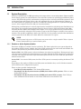
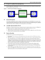
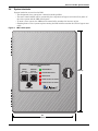
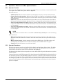
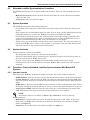
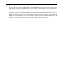
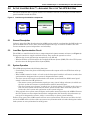
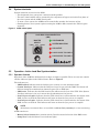
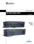
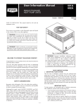
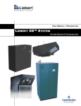
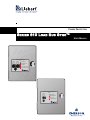
POWER PROTECTION
SERIES 610 LOAD BUS SYNC™
USER MANUAL
LOAD BUS SYNCHRONIZATION
(LBS)
MODE
SELECT
OFF
AUTO
MASTER
SELECT
LOAD 1 LOAD 2
LBS ENABLED
SYSTEM NON-SYNC
LBS ACTIVE
LOAD 1 SYNC TO LOAD 2
LOAD 2 SYNC TO LOAD 1
LAMP TEST
EXTENDED LOAD BUS SYNCHRONIZATION
(ELBS)
MODE
SELECT
OFF
AUTO
LBS ENABLED
SYSTEM NON-SYNC
LBS ACTIVE
LOAD 1 SYNC TO DMS
LAMP TEST
TABLE OF CONTENTS
1.0
INTRODUCTION . . . . . . . . . . . . . . . . . . . . . . . . . . . . . . . . . . . . . . . . . . . . . . . . . . . . . . . . . .1
1.1
System Description. . . . . . . . . . . . . . . . . . . . . . . . . . . . . . . . . . . . . . . . . . . . . . . . . . . . . . . . . . . 1
1.1.1
Passive or Active Synchronization. . . . . . . . . . . . . . . . . . . . . . . . . . . . . . . . . . . . . . . . . . . . . . . . 1
2.0
PASSIVE LOAD BUS SYNCHRONIZATION . . . . . . . . . . . . . . . . . . . . . . . . . . . . . . . . . . . . . . .2
2.1
General Description . . . . . . . . . . . . . . . . . . . . . . . . . . . . . . . . . . . . . . . . . . . . . . . . . . . . . . . . . . 2
2.2
Load Bus Synchronization Circuit . . . . . . . . . . . . . . . . . . . . . . . . . . . . . . . . . . . . . . . . . . . . . . 2
2.3
System Operation . . . . . . . . . . . . . . . . . . . . . . . . . . . . . . . . . . . . . . . . . . . . . . . . . . . . . . . . . . . . 2
2.4
System Interlocks . . . . . . . . . . . . . . . . . . . . . . . . . . . . . . . . . . . . . . . . . . . . . . . . . . . . . . . . . . . . 3
2.5
Operation—Passive Load Bus Synchronization . . . . . . . . . . . . . . . . . . . . . . . . . . . . . . . . . . . . 4
2.5.1
2.5.2
Operator Controls . . . . . . . . . . . . . . . . . . . . . . . . . . . . . . . . . . . . . . . . . . . . . . . . . . . . . . . . . . . . . 4
Operator Procedures. . . . . . . . . . . . . . . . . . . . . . . . . . . . . . . . . . . . . . . . . . . . . . . . . . . . . . . . . . . 4
3.0
PASSIVE EXTENDED LOAD BUS SYNCHRONIZATION WITH LIEBERT UPS SYSTEMS . . . . . . . .5
3.1
System Description. . . . . . . . . . . . . . . . . . . . . . . . . . . . . . . . . . . . . . . . . . . . . . . . . . . . . . . . . . . 5
3.2
Extended Load Bus Synchronization & MSDA Controllers. . . . . . . . . . . . . . . . . . . . . . . . . . . 6
3.3
System Operation . . . . . . . . . . . . . . . . . . . . . . . . . . . . . . . . . . . . . . . . . . . . . . . . . . . . . . . . . . . . 7
3.4
System Interlocks . . . . . . . . . . . . . . . . . . . . . . . . . . . . . . . . . . . . . . . . . . . . . . . . . . . . . . . . . . . . 7
3.5
Operation—Passive Extended Load Bus Synchronization With Liebert UPS Systems . . . . 7
3.5.1
3.5.2
Operator Controls . . . . . . . . . . . . . . . . . . . . . . . . . . . . . . . . . . . . . . . . . . . . . . . . . . . . . . . . . . . . . 7
Operator Procedures. . . . . . . . . . . . . . . . . . . . . . . . . . . . . . . . . . . . . . . . . . . . . . . . . . . . . . . . . . . 8
4.0
PASSIVE EXTENDED LOAD BUS SYNCHRONIZATION WITH MIXED UPS SYSTEMS . . . . . . . . .9
4.1
System Description. . . . . . . . . . . . . . . . . . . . . . . . . . . . . . . . . . . . . . . . . . . . . . . . . . . . . . . . . . . 9
4.2
Extended Load Bus Synchronization Controllers. . . . . . . . . . . . . . . . . . . . . . . . . . . . . . . . . . 10
4.3
System Operation . . . . . . . . . . . . . . . . . . . . . . . . . . . . . . . . . . . . . . . . . . . . . . . . . . . . . . . . . . . 10
4.4
System Interlocks . . . . . . . . . . . . . . . . . . . . . . . . . . . . . . . . . . . . . . . . . . . . . . . . . . . . . . . . . . . 10
4.5
Operation—Passive Extended Load Bus Synchronization With Mixed UPS Systems . . . . 10
4.5.1
4.5.2
Operator Controls . . . . . . . . . . . . . . . . . . . . . . . . . . . . . . . . . . . . . . . . . . . . . . . . . . . . . . . . . . . . 10
Operator Procedures. . . . . . . . . . . . . . . . . . . . . . . . . . . . . . . . . . . . . . . . . . . . . . . . . . . . . . . . . . 11
5.0
ACTIVE LOAD BUS SYNC™—AVAILABLE ONLY FOR TWO UPS SYSTEMS . . . . . . . . . . . . . 12
5.1
General Description . . . . . . . . . . . . . . . . . . . . . . . . . . . . . . . . . . . . . . . . . . . . . . . . . . . . . . . . . 12
5.2
Load Bus Synchronization Circuit . . . . . . . . . . . . . . . . . . . . . . . . . . . . . . . . . . . . . . . . . . . . . 12
5.3
System Operation . . . . . . . . . . . . . . . . . . . . . . . . . . . . . . . . . . . . . . . . . . . . . . . . . . . . . . . . . . . 12
5.4
System Interlocks . . . . . . . . . . . . . . . . . . . . . . . . . . . . . . . . . . . . . . . . . . . . . . . . . . . . . . . . . . . 13
5.5
Operation—Active Load Bus Synchronization . . . . . . . . . . . . . . . . . . . . . . . . . . . . . . . . . . . . 13
5.5.1
5.6
Operator Controls . . . . . . . . . . . . . . . . . . . . . . . . . . . . . . . . . . . . . . . . . . . . . . . . . . . . . . . . . . . . 13
Operator Procedures . . . . . . . . . . . . . . . . . . . . . . . . . . . . . . . . . . . . . . . . . . . . . . . . . . . . . . . . 14
i
FIGURES
Figure 1
Figure 2
Figure 3
Figure 4
Figure 5
Figure 6
Figure 7
Figure 8
Figure 9
Load bus synchronization components . . . . . . . . . . . . . . . . . . . . . . . . . . . . . . . . . . . . . . . . . . . . . . . 2
LBS control panel . . . . . . . . . . . . . . . . . . . . . . . . . . . . . . . . . . . . . . . . . . . . . . . . . . . . . . . . . . . . . . . . 3
Extended load bus synchronization—all Liebert UPS . . . . . . . . . . . . . . . . . . . . . . . . . . . . . . . . . . . 5
ELBS control panel . . . . . . . . . . . . . . . . . . . . . . . . . . . . . . . . . . . . . . . . . . . . . . . . . . . . . . . . . . . . . . . 6
Master select and distribution assembly (MSDA). . . . . . . . . . . . . . . . . . . . . . . . . . . . . . . . . . . . . . . 6
Extended load bus synchronization—mixed UPS systems. . . . . . . . . . . . . . . . . . . . . . . . . . . . . . . . 9
ELBS control panel . . . . . . . . . . . . . . . . . . . . . . . . . . . . . . . . . . . . . . . . . . . . . . . . . . . . . . . . . . . . . . . 9
Load bus synchronization components . . . . . . . . . . . . . . . . . . . . . . . . . . . . . . . . . . . . . . . . . . . . . . 12
ALBS control panel . . . . . . . . . . . . . . . . . . . . . . . . . . . . . . . . . . . . . . . . . . . . . . . . . . . . . . . . . . . . . . 13
ii
Introduction
1.0
INTRODUCTION
1.1
System Description
Liebert’s Load Bus Sync™ (LBS) option keeps the output of two or more independent Uninterruptible
Power Supply systems in synchronization, even when the systems are operating from different power
sources. Any UPS will typically synchronize to its bypass source. As long as the UPS systems are tied
to the same input and bypass sources, they will automatically stay in synchronization. However, if
the UPS systems are operating on batteries, on different backup generators or asynchronous bypass
sources, their outputs will tend to drift out of synchronization.
Maintaining synchronization is critically important for installations with dual power distribution systems. These sites typically feature Liebert Precision Power Centers (PPC) with Liebert Static Bus
Transfer Switches (STSs). Each STS has dual inputs: it can receive power from any connected UPS,
and switch seamlessly among the UPS systems as long as the UPS outputs are held in close synchronization. This provides redundancy down to the PPC level. It also permits one half of the distribution
system (upstream of the STS) to be taken offline for maintenance or repairs.
NOTE
In this manual reference to a UPS system may mean either a single-module UPS or a System
Control Cabinet (SCC) of a multi-module system.
1.1.1
Passive or Active Synchronization
Two forms of LBS are available, Passive and Active. The form required for your system depends on
the number of UPS systems, whether the Liebert UPS systems are the same model and whether the
Liebert UPS systems are paired with another manufacturer’s UPS.
Passive LBS - One UPS system is selected as Master, the others become Slaves. During normal operation all systems will function independently of each other. Should the UPS systems lose synchronization with each other for more than a pre-determined period of time, the slave UPSs will synchronize
with the master UPS.
Active LBS - In an Active LBS system, the Slave UPS system is constantly tracking the Master UPS
system.
Depending on the number of UPSs in the LBS system and whether they are all of Liebert manufacture will dictate the configuration required.
There are three possible configurations:
• Load Bus Synchronization—Two Liebert UPS systems
• Extended Load Bus Synchronization (ELBS) with Liebert UPS systems—Three or more
Liebert UPS systems
• Extended Load Bus Synchronization (ELBS) with mixed UPS systems—Two UPS systems of different Liebert models or one Liebert UPS and one non-Liebert UPS
1
Passive Load Bus Synchronization
2.0
PASSIVE LOAD BUS SYNCHRONIZATION
The Load Bus Sync™ (LBS) option consists of an interface board in each UPS plus one LBS control
panel installed between the UPSs.
Figure 1
Load bus synchronization components
LBS
Interface
Board
LBS Control Panel
UPS System #1
2.1
LBS
Interface
Board
UPS System #2
General Description
The Liebert Load Bus Sync option works by synchronizing the slave UPS (DSS) to the output of the
master UPS (DMS). Furthermore, the LBS is dormant until the two UPSs drift more than a predetermined amount out of synchronization. There are no other connections between the logic or controls of
either UPS. This ensures maximum system independence and reliability.
2.2
Load Bus Synchronization Circuit
The LBS is a controller that fits into a compact 20 x 24 inch (508 x 610mm) enclosure (see Figure 2).
Front panel controls are simple and fault tolerant. They enable the operator to select:
1. Whether the circuit will function automatically or be “Off,” and
2. Whether UPS #1 or UPS #2 will be the Designated Master System (DMS). The other UPS system
then becomes the Designated Slave System (DSS).
2.3
System Operation
The LBS option performs the following functions:
1. Continuously senses the phase relationship between the outputs of the two UPSs that make up
the system.
2. If the two systems lose synchronization with each other for more than a predetermined period of
time (adjustable from 2 to 5 seconds), the LBS will synchronize the Designated Slave System
(DSS) to the Designated Master System (DMS) if the Auto/Off switch is in the Auto position. DSS
and DMS are selected manually via the master system select switch. If the DSS is on bypass and
unable to synchronize to the DMS, the DMS will then synchronize to the output bus of the DSS.
This re-selection of master will be accomplished automatically.
3. Continuously monitors the quality and synchronization of the bypass input voltage to both
systems. Once quality and synchronization between the two have been re-established for five
seconds, the LBS will revert to separate synchronization for both systems, each synchronized to
its own bypass.
4. Failure of any part of the LBS controls will not cause system failure. The worst case effect of a
failure in the LBS will be a failure of the two systems to synchronize with each other during times
when both systems are not synchronized to utility power.
2
Passive Load Bus Synchronization
2.4
System Interlocks
System interlocks are used on the LBS:
• The designated slave system has a manual transfer prohibit.
• The static switch inhibit will be governed by the comparison of bypass and critical bus phase of
the slave system and the LBS control panel.
• To start a slave system, the LBS must be turned off to transfer the inverter on-line.
• Shutting down a slave system requires turning the LBS to Off to transfer the UPS to bypass manually.
Figure 2
LBS control panel
LOAD BUS SYNCHRONIZATION
(LBS)
MODE
SELECT
OFF
AUTO
MASTER
SELECT
LOAD 1 LOAD 2
LBS ENABLED
SYSTEM NON-SYNC
LBS ACTIVE
LOAD 1 SYNC TO LOAD 2
LOAD 2 SYNC TO LOAD 1
LAMP TEST
20"
508mm)
3
24"
610mm)
Passive Load Bus Synchronization
2.5
Operation—Passive Load Bus Synchronization
2.5.1
Operator Controls
Operation of the LBS has been kept as simple as possible. There are only three controls and five indicator lights on the LBS control panel. Refer to Figure 2.
The indicators are:
• LBS Enabled. Indicates that the load bus synchronization circuitry is in the Automatic mode.
• System Non-Synchronization. Indicates that the DSS is no longer in synchronization with the
DMS. This alarm will indicate during the transition from internal bypass synchronization to DMS
synchronization.
• LBS Active. Indicates that the LBS circuitry has taken over the synchronization of the UPS. If
the System Non-Synchronization indicator is also on, it means that synchronization is in process.
• Load 1 Synchronization to Load 2. Indicates that the UPS critical bus is synchronized to the
output of the DMS, in this case UPS #2. This indicator will turn on when the synchronization process is complete.
• Load 2 Synchronization to Load 1. Indicates that the UPS critical bus is synchronized to the
output of the DMS, in this case UPS #1. This indicator will turn on when the synchronization process is complete.
NOTE
All indicators mentioned above are available via Form C dry contacts for remote monitoring.
LBS controls are:
• Mode Select Switch. Provides manual selection of automatic operation or “Off” modes. In the
Automatic mode, the LBS will be enabled. In the Off mode, both UPSs will synchronize independently.
• Master Select Switch. Provides manual selection of the DMS source. The LBS circuitry will
automatically switch DMS sources should the initially selected DSS transfer to bypass.
• Lamp Test. Push this button to test indicator lights.
2.5.2
Operator Procedures
The only two operator controls are the Mode Select Switch and the Master Select Switch. The Mode
Select Switch can be left in the Automatic position all the time. The Off position can be selected at
times when it is desired to let the UPSs synchronize independently.
The Master Select Switch allows the operator to choose which UPS will provide the reference synchronization signal.
In normal operation, both UPS systems will be functioning and the LBS Mode Select Switch will be in
the Automatic position. The LBS Enable indicator will be lit, as will one of the indicators for Load X
synchronization to Load Y. If the two UPS drift out of synchronization (while on generator or battery,
for example), the LBS Active and System Non-Sync indicators will be lighted. The Load X Synchronization to Load Y indicator will be off during the synchronization process and turn back on when the
process is complete.
4
Passive Extended Load Bus Synchronization with Liebert UPS Systems
3.0
PASSIVE EXTENDED LOAD BUS SYNCHRONIZATION WITH LIEBERT UPS
SYSTEMS
3.1
System Description
The Extended Load Bus Sync™ option consists of an interface board and an ELBS panel for each
UPS, plus one Master Select and Distribution Assembly (MSDA) for the complete system. For multimodule systems, the interface board will be in each System Control Cabinet (SCC).
The ELBS assemblies are packaged in wall-mount enclosures, with each mounted as close as possible
to the UPS being controlled. The MSDA is also packaged in a wall-mount enclosure and installed near
the UPS chosen as the Designated Master System (DMS). The other UPS systems will be considered
Designated Slave Systems (DSS).
Figure 3
Extended load bus synchronization—all Liebert UPS
LBS
Interface
Board
ELBS
Control
Panel
Master Select
& Distribution
Assembly (MSDA)
UPS System #1
ELBS
Control
Panel
LBS
Interface
Board
UPS System #2
ELBS
Control
Panel
ELBS
Control
Panel
LBS
Interface
Board
LBS
Interface
Board
UPS System #4
UPS System #3
The Liebert ELBS option works by synchronizing the various slave UPSs (DSS) to the output of the
DMS. The ELBS is dormant until the UPS systems drift out of synchronism by more than a predetermined amount. There are no other connections between the logic or controls of the UPS systems. This
ensures maximum system independence and reliability.
5
Passive Extended Load Bus Synchronization with Liebert UPS Systems
Figure 4
ELBS control panel
EXTENDED LOAD BUS SYNCHRONIZATION
(ELBS)
LBS ENABLED
MODE
SELECT
OFF
SYSTEM NON-SYNC
AUTO
LBS ACTIVE
LOAD 1 SYNC TO DMS
LAMP TEST
3.2
Extended Load Bus Synchronization & MSDA Controllers
The ELBS controller fits into a compact 20x24 inch (508 x 610mm) enclosure. There are two controls
on the front panel:
• Mode Select Switch—Provides manual selection of whether the circuit will function automatically or be “Off,” and
• Lamp Test—Push to test indicator lights
The MSDA Controller has one control:
• Master Select Switch: Provides manual selection of DMS Source. Two or more UPSs feed the
MSDA, so the selection of the DMS would either be Source 1 or Source 2, with Source 1 being the
first choice and Source 2 being the contingency source.
Figure 5
Master select and distribution assembly (MSDA)
MASTER SELECT AND DISTRIBUTION ASSEMBLY
(MDSA)
MASTER
SELECT
Source 2
UPS 1
Source 3
UPS 2
Source 1
Source 4
UPS 3
UPS 4
NOTE
A four-UPS System unit is shown. MSDA units are available for three, four, five and six UPS
systems.
6
Passive Extended Load Bus Synchronization with Liebert UPS Systems
3.3
System Operation
The ELBS option performs the following functions:
• Continuously senses the phase relationship between the outputs of the slave UPSs (DSS) and the
DMS.
• If the systems lose synchronization with each other for more than a predetermined period of time
(adjustable from 2 to 5 seconds), the ELBS will synchronize the Designated Slave Systems (DSS)
to the Designated Master System (DMS) if the mode switch is in the Auto position. DSS and DMS
are selected manually via the master system select switch on the MSDA.
• Continuously monitors the quality and synchronization of the bypass input voltage to all systems.
Once quality and synchronization have been re-established for five seconds, the ELBS will revert
to separate synchronization for all systems, each synchronized to its own bypass.
• Failure of any part of the ELBS controls will not cause system failure. The worst case effect of a
failure in the ELBS will be a failure of the systems to synchronize with each other during times
when the systems are not synchronized to utility power.
3.4
System Interlocks
System interlocks are used on the ELBS:
• The designated slave system has a manual transfer prohibit.
• The static switch inhibit will be governed by the comparison of bypass and critical bus phase of
the slave system and the ELBS control panel.
• To start a slave system, the ELBS must be turned off to transfer the inverter on-line.
• Shutting down a slave system requires turning the ELBS to Off to transfer the UPS to bypass
manually.
3.5
Operation—Passive Extended Load Bus Synchronization With Liebert UPS
Systems
3.5.1
Operator Controls
Operation of the ELBS has been kept as simple as possible. The system indicator lights are:
• ELBS Enabled (on ELBS control panel)—Indicates that the load bus synchronization circuitry is
in the Automatic mode.
• System Non-Sync (on ELBS control panel)—Indicates that the DSS is no longer in synchronization with the DMS. This alarm will indicate during the transition from internal bypass synchronization to DMS synchronization.
• ELBS Active (on ELBS control panel)—Indicates that the LBS circuitry has taken over the synchronization of the UPS. If the System Non-Sync indicator is also on, it means that synchronization is in process.
• Load Sync to DMS (on ELBS control panel)—Indicates that the critical load bus is synchronized
to the output of the DMS. This indicator will turn on when the synchronization process is complete.
• UPS 1 (on MSDA)—Indicates that UPS 1 is the DMS.
• UPS (2-X) (on MSDA)—Indicates that UPS 2 (or 3 or 4) is the DMS.
NOTE:
All indicators above are available via Form C dry contacts for remote monitoring.
ELBS controls are:
• Mode Select—Provides manual selection of automatic operation or “Off” modes. In the Automatic mode, the ELBS will be enabled. In the Off mode, slave UPSs will synchronize independently (see Figure 4).
• Lamp Test—Press this button to test indicator lights (see Figure 4).
MSDA control is:
• Master Select. Provides manual selection of the DMS source. The ELBS circuitry will automatically switch DMS sources should the initially selected DMS lose its bypass input (see Figure 5).
7
Passive Extended Load Bus Synchronization with Liebert UPS Systems
3.5.2
Operator Procedures
The only two operator controls are the Mode Select Switch and the Master Select Switch. The Mode
Select Switch can be left in the Automatic position all the time. The Off position can be selected for
maintenance or other times when it is desired to let the UPSs synchronize independently.
The Master Select Switch allows the operator to choose which UPS will provide the reference synchronization signal.
In normal operation, all UPS systems will be functioning and the ELBS Mode Select switch will be in
the Automatic position. The LBS Enable indicator will be lit, as will the indicator for Load Sync to
DMS. If one of the UPSs drifts out of synchronization (while on generator or battery, for example), the
LBS Active and System Non-Sync indicators will be lit. The Load Sync to DMS indicator will be off
during the synchronization process and turn back on when the process is complete.
8
Passive Extended Load Bus Synchronization With Mixed UPS Systems
4.0
PASSIVE EXTENDED LOAD BUS SYNCHRONIZATION WITH MIXED UPS SYSTEMS
4.1
System Description
The Extended Load Bus Sync™ (ELBS) option for mixed UPS systems permits synchronizing the outputs of a combination of either:
• different models of Liebert UPS systems
OR
• a Liebert UPS and a non-Liebert UPS.
The option consists of an interface board and an ELBS assembly for the Liebert UPS designated as
the slave system (DSS), plus one fuse kit for the Designated Master System (DMS). If a non-Liebert
UPS system is used, that UPS will always be designated as the master system. If different Liebert
UPS models are connected, one Liebert UPS system will be designated as the master system.
For multi-module systems, the interface board will be in the Liebert System Control Cabinet (SCC).
The ELBS assembly is packaged in a wall-mount enclosure, mounted as close as possible to the UPS
being controlled.
Figure 6
Extended load bus synchronization—mixed UPS systems
LBS
Interface
Board
ELBS Control
Panel
Liebert UPS System
(always designated slave
in this configuration)
Fuse Kit
Designated
Master UPS
System
The ELBS option works by bringing the DSS into synchronization with the DMS. Furthermore, the
ELBS is dormant until the DSS drifts more than a predetermined amount out of synchronization with
the DMS. There are no other connections between the logic or controls of the UPSs. This ensures maximum system independence and reliability.
Figure 7
ELBS control panel
EXTENDED LOAD BUS SYNCHRONIZATION
(ELBS)
LBS ENABLED
MODE
SELECT
OFF
SYSTEM NON-SYNC
AUTO
LBS ACTIVE
LOAD 1 SYNC TO DMS
LAMP TEST
9
Passive Extended Load Bus Synchronization With Mixed UPS Systems
4.2
Extended Load Bus Synchronization Controllers
The ELBS Controller fits into a compact 20x24 inch enclosure. There are only two front panel controls:
• Mode Select Switch: Provides manual selection of whether the circuit will function automatically or be “Off,” and
• Lamp Test: Push to test indicator lights.
4.3
System Operation
The ELBS option performs the following functions:
• Continuously senses the phase relationship between the outputs of the UPSs that make up the
system.
• If the systems lose synchronization with each other for more than a predetermined period of time
(adjustable from 2 to 5 seconds), the ELBS will synchronize the DSS to the DMS
• Continuously monitors the quality and synchronization of the output voltage of the DSS. Once
quality and synchronization have been re-established for five seconds, the ELBS will revert to
separate synchronization for the DSS, each synchronized to its own bypass.
• Failure of any part of the ELBS controls will not cause system failure. The worst case effect of a
failure in the ELBS will be a failure of the systems to synchronize with each other during times
when the systems are not synchronized to utility power.
4.4
System Interlocks
System interlocks are used on the ELBS:
• The designated slave system has a manual transfer prohibit.
• The static switch inhibit will be governed by the comparison of bypass and critical bus phase of
the slave system and the ELBS control panel.
• To start a slave system, the ELBS must be turned off to transfer the inverter on-line.
• Shutting down a slave system requires turning the ELBS to Off to transfer the UPS to bypass
manually.
4.5
Operation—Passive Extended Load Bus Synchronization With Mixed UPS
Systems
4.5.1
Operator Controls
Operation of the ELBS has been kept as simple as possible. The system indicator lights are:
• ELBS Enabled—Indicates that the load bus synchronization circuitry is in the Automatic mode.
• System Non-Sync—Indicates that the DSS is no longer in synchronization with the DMS. This
alarm will indicate during the transition from internal bypass synchronization to DMS synchronization.
• ELBS Active—Indicates that the LBS circuitry has taken over the synchronization of the UPS. If
the System Non-Synchronization indicator is also on, it means that synchronization is in process.
• Load 1 Sync to DMS—Indicates that the critical load bus is synchronized to the output of the
DMS. This indicator will turn on when the synchronization process is complete.
NOTE:
All indicators above are available via Form C dry contacts for remote monitoring.
ELBS controls are:
• Mode Select—Provides manual selection of automatic operation or “Off” modes. In the Automatic mode, the ELBS will be enabled. In the Off mode, both UPSs will synchronize independently (see Figure 4).
• Lamp Test—Press this button to test indicator lights (see Figure 4).
10
Passive Extended Load Bus Synchronization With Mixed UPS Systems
4.5.2
Operator Procedures
The only operator control is the Mode Select Switch. The Mode Select Switch can be left in the Automatic position all the time. The Off position can be selected for maintenance or other times when it is
desired to let the UPSs synchronize independently.
In normal operation, all UPS systems will be functioning and the ELBS Mode Select switch will be in
the Automatic position. The ELBS Enable indicator will be lit, as will the indicator for Load Sync to
DMS. If one of the UPSs drifts out of synchronization (while on generator or battery, for example), the
ELBS Active and System Non-Sync indicators will be lit. The Load Sync to DMS indicator will be off
during the synchronization process and turn back on when the process is complete.
11
Active Load Bus Sync™—Available Only for Two UPS Systems
5.0
ACTIVE LOAD BUS SYNC™—AVAILABLE ONLY FOR TWO UPS SYSTEMS
The Active Load Bus Sync™ option consists of an interface board in each UPS plus one LBS control
panel installed between the UPSs.
Figure 8
Load bus synchronization components
LBS
Interface
Board
Active LBS Control
Panel
UPS System #1
5.1
LBS
Interface
Board
UPS System #2
General Description
Liebert’s Active Load Bus Synchronization (ALBS) option works by synchronizing the DSS to the output of the DMS. There are no other connections between the logic or controls of either UPS. This
ensures maximum system independence and reliability.
5.2
Load Bus Synchronization Circuit
The ALBS is a controller that fits into a compact 20x24 inch (508 x 610mm) enclosure (see Figure 9).
Front panel controls are simple and fault tolerant. They enable the operator to select:
• Whether the circuit will function automatically or be Off and
• Whether UPS #1 or UPS #2 will be the Designated Master System (DMS). The other UPS system
then becomes the Designated Slave System (DSS).
5.3
System Operation
The ALBS option performs the following functions:
• Continuously senses the phase relationship between the outputs of the two UPSs that make up
the system.
• When ALBS is turned to Load 1 or Load 2 (via the front panel switch) it will wait 5 seconds, then
synchronize the designated slave system to designated master system.
• The slave system will remain synchronized to the master system until the ALBS control panel
switch is turned to the OFF position or:
• The master system synchronization signal goes away (out of voltage tolerance) in which case
the slave system will return to synchronization with its internal bypass.
• The slave system goes to bypass, in which case, if critical voltage is available at the slave system, the slave system will become the master system and the other connected system will
become the slave system and synchronize to the system in bypass.
• If the original slave system comes off bypass and resumes normal operation, the ALBS will return
the UPS systems to their original master/slave configuration (the manually selected master system again is designated as master, with a 5 second delay to ensure system stability).
Failure of any part of the ALBS controls will not cause system failure. The worst case effect of a failure in the ALBS will be a failure of the two systems to synchronize with each other during times when
both systems are not synchronized to utility power.
12
Active Load Bus Sync™—Available Only for Two UPS Systems
5.4
System Interlocks
System interlocks are used on the ALBS:
• The designated slave system has a manual transfer prohibit.
• The static switch inhibit will be governed by the comparison of bypass and critical bus phase of
the slave system and the ALBS control panel.
• To start a slave system, the ALBS must be turned off to transfer the inverter on-line.
• Shutting down a slave system requires turning the ALBS to Off to transfer the UPS to bypass
manually.
Figure 9
ALBS control panel
LOAD BUS SYNCHRONIZATION
(LBS)
LBS ENABLED
MASTER
SELECT
LOAD 1
OFF
SYSTEM NON-SYNC
LOAD 2
LBS ACTIVE
LOAD 1 SYNC TO LOAD 2
LOAD 2 SYNC TO LOAD 1
LAMP TEST
5.5
Operation—Active Load Bus Synchronization
5.5.1
Operator Controls
Operation of the ALBS has deliberately been kept as simple as possible. There are only two controls
and five indicator lights on the LBS enclosure. Refer to Figure 2.
The indicators are:
• LBS Enabled. Indicates that the load bus sync circuitry is in the Automatic mode.
• System Non-Sync. Indicates that the DSS is no longer in sync with the DMS. This alarm will
indicate during the transition from internal bypass sync to DMS sync.
• LBS Active. Indicates that the LBS circuitry has taken over the sync of the UPS. If the System
Non-Sync indicator is also on, it means that synchronization is in process.
• Load 1 Sync to Load 2. Indicates that the UPS critical bus is synchronized to the output of the
DMS, in this case UPS #2. This indicator will turn on when the sync process is complete.
• Load 2 Sync to Load 1. Indicates that the UPS critical bus is synchronized to the output of the
DMS, in this case UPS #1. This indicator will turn on when the sync process is complete.
NOTE
All indicators mentioned above are available via Form C dry contacts for remote monitoring.
ALBS controls are:
• Master Select Switch (three position switch). Provides manual selection of the DMS source.
• Lamp Test. Push this button to test indicator lights.
13
Active Load Bus Sync™—Available Only for Two UPS Systems
5.6
Operator Procedures
The only operator control is the Master Select Switch. This switch allows the operator to choose which
UPS will provide the reference synchronization signal.
The Off position can be selected at times when it is desired to let the UPSs synchronize independently.
In normal operation, both UPS systems will be functioning and the Master Select Switch will be in
the Load 1 or load 2 position. The LBS Enable indicator will be lit, as will one of the indicators for
Load X Synchronization to Load Y.
14
POWER PROTECTION
SERIES 610 Load Bus Sync™
The Company Behind the Products
With over a million installations around the globe,
Liebert is the world leader in computer protection
systems. Since its founding in 1965, Liebert has
developed a complete range of support and
protection systems for sensitive electronics:
•
•
•
•
•
Environmental systems—close-control air
conditioning from 1 to 60 tons
Power conditioning and UPS with power
ranges from 300 VA to more than 1000 kVA
Integrated systems that provide both
environmental and power protection in a
single, flexible package
Monitoring and control—from systems of any
size or location, on-site or remote
Service and support through more than 100
service centers around the world and a 24/7
Customer Response Center
While every precaution has been taken to ensure
the accuracy and completeness of this literature,
Liebert Corporation assumes no responsibility and
disclaims all liability for damages resulting from
use of this information or for any errors or
omissions.
© 2005 Liebert Corporation
All rights reserved throughout the world.
Specifications subject to change without notice.
® Liebert and the Liebert logo are registered
trademarks of Liebert Corporation. All names
referred to are trademarks or registered
trademarks of their respective owners.
SL-30105 (3/05) Rev. 1
USER MANUAL
Technical Support/Service
Web Site
www.liebert.com
Monitoring
800-222-5877
[email protected]
Outside the US: 614-841-6755
Single-Phase UPS
800-222-5877
[email protected]
Outside the US: 614-841-6755
Three-Phase UPS
800-543-2378
[email protected]
Environmental Systems
800-543-2778
Outside the United States
614-888-0246
Locations
United States
1050 Dearborn Drive
P.O. Box 29186
Columbus, OH 43229
Italy
Via Leonardo Da Vinci 8
Zona Industriale Tognana
35028 Piove Di Sacco (PD)
+39 049 9719 111
Fax: +39 049 5841 257
Asia
23F, Allied Kajima Bldg.
138 Gloucester Road
Wanchai
Hong Kong
+852 2 572 2201
Fax: +852 2 831 0114