1
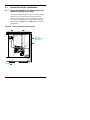
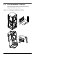
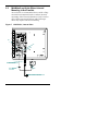
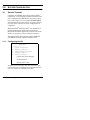
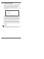
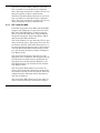
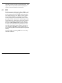
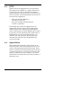
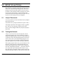
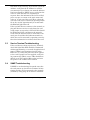
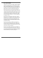
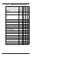
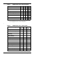
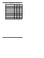
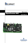
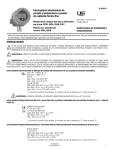
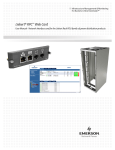
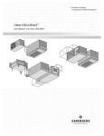
SITE MONITORING
OpenComms NIC
Network Interface Card
Installation &
User Manual
NOTE TO USER
To help us better serve you, please contact us with
any comments you have about this manual or this
product in general.
We encourage you to comment and would appreciate your assistance in improving Liebert products.
Site Products Applications Engineering (U.S.):
[email protected]
TABLE OF CONTENTS
NOTE TO USER2
1.0
INTRODUCTION
1.1
NIC Specifications . . . . . . . . . . . . . . . . . . . . . 3
2.0
INSTALLATION
2.1
Internal Retrofit Kit Installations. . . . . . . . . 5
2.1.1
2.1.2
2.1.3
Physical Installation—Deluxe System/3
and Industrial Cooling Series (ICS)5
Physical Installation—Challenger . . . . . . 7
System Wiring (SM, AM, AG microprocessors)8
2.2
MiniMate2 and Units Where Internal Mounting is Not Feasible11
2.3
User Connections . . . . . . . . . . . . . . . . . . . . . 13
2.3.1
Physical 10BaseT Connection . . . . . . . . 13
2.4
DIP Switch Settings . . . . . . . . . . . . . . . . . . . 13
3.0
SYSTEM CONFIGURATION
3.1
Service Terminal . . . . . . . . . . . . . . . . . . . . . 14
3.1.1
3.1.2
3.1.3
3.1.4
3.1.5
3.1.6
3.1.7
Configuring the NIC . . . . . . . . . . . . . . . 14
System Information Menu . . . . . . . . . . . 15
Network Interface Menu. . . . . . . . . . . . . 16
SNMP Communications Menu . . . . . . . . 17
Firmware Update Menu . . . . . . . . . . . . . 18
Factory Settings Menu . . . . . . . . . . . . . . 18
BOOTP and DHCP Mode . . . . . . . . . . . . 19
4.0
OPERATION
4.1
SNMP . . . . . . . . . . . . . . . . . . . . . . . . . . . . . . 20
4.2
MIB . . . . . . . . . . . . . . . . . . . . . . . . . . . . . . . . 20
4.3
HTTP. . . . . . . . . . . . . . . . . . . . . . . . . . . . . . . 21
4.4
System Reset . . . . . . . . . . . . . . . . . . . . . . . . 21
5.0
NIC SET UP AND TESTING
5.1
Jumper Placements . . . . . . . . . . . . . . . . . . . 24
5.2
Testing the Network . . . . . . . . . . . . . . . . . . 24
FIGURES
Figure 1
Figure 2
Figure 3
Figure 4
Figure 5
Figure 6
Figure 7
Figure 8
Typical System Configuration . . . . . . . . . . . . 2
Deluxe System/3 Control Cavity . . . . . . . . . . . 5
Deluxe System/3 120" Chilled Water Control
Cavity6
ICS Control Cavity. . . . . . . . . . . . . . . . . . . . . . 6
Challenger Installation Location . . . . . . . . . . 7
Challenger 3000 Control Cavity . . . . . . . . . . . 8
NIC-ENCL1, Internal View. . . . . . . . . . . . . . 11
Card Component Locations . . . . . . . . . . . . . . 23
1.0
INTRODUCTION
Congratulations on your choice of the Liebert
OpenComms NIC product.
The OpenComms NIC transforms Liebert units
into intelligent managed nodes on your network,
enabling in-band communications with network
management systems (NMS). For the first time,
the system that monitors the well-being of your
computing/communication infrastructure can comprehensively monitor your Liebert equipment as
well.
The following protocols are supported:
SNMP v1, v2c
HTTP v1.1
These protocols allow simple integration into the
network management system, thus leveraging
prior investment and established procedures.
Alternately, Liebert units may be monitored “ondemand” via a Web browser from anywhere network access is permitted. The NIC’s IP address
will be visible on the network so that access to the
web page will be achievable.
Introduction
1
Figure 1
2
Typical System Configuration
Introduction
1.1
NIC Specifications
Electrical Requirements:
Voltage: 18 VAC to 24 VAC
50/60 Hz, Single Phase
12 VDC to 36 VDC
Power:
6 VA maximum
Environmental Conditions:
Operating Ambient Temperature: 5°C to 40°C
(41°F to 104°F)
Storage Ambient Temperature: -20°C to 60°C
(-4°F to 140°F)
Relative Humidity:
Humidity: 10% to 90% RH (non-condensing)
Dimensions:
Net: 178 mm x 102 mm x 38 mm, 0.2 kg
(7.0" x 4.0" x 1.5", 0.4 lbs)
As shipped: 248 mm x 178 mm x 64 mm, 0.6 kg
(9.75" x 7.0" x 2.5", 1.3 lbs)
Compatibility:
Environmental
Advanced Graphics (AG)
Advanced Microprocessor (AM)
Standard Microprocessor (SM)
MiniMate2, 8-Ton Controller
MiniMate2, 1½ - 5 Ton Controller
Level 10
Level 0
3-Phase UPS
7200 Series
Introduction
3
2.0
INSTALLATION
The OpenComms NIC card may be ordered as a
factory-installed option, in a kit for field-retrofit to
existing Liebert units or as a self-contained unit in
its own enclosure.
If ordered as a factory-installed option, proceed
directly to the section on User Connections.
As a retrofit kit, the circuit board is secured to a
metal mounting plate. The back of the mounting
plate is affixed to a flat metal surface in a low-voltage section of the Environmental unit.
The self-contained model packages the interface
card inside a steel enclosure, for mounting external to the Liebert unit. A low-voltage transformer
is also provided.
4
Installation
2.1
Internal Retrofit Kit Installations
2.1.1
Physical Installation—Deluxe System/3 and
Industrial Cooling Series (ICS)
Position the OpenComms card in the low voltage/
control cavity of the Liebert Deluxe System/3
units. Use three #8 x 1/2" sheet metal screws to
attach the mounting plate to the Environmental
unit. Refer to Figure 2 and Figure 3 for typical
positioning.
Figure 2
Deluxe System/3 Control Cavity
F3
P4
P43
E1
(
P24
)
T1
F1
LI EBERT
P 44
F2
4
1
F4
8
P43
ASS Y NO.
4C14651G RE V
5
P25
TB2
CONNECTS TO
SCREW TERMINALS 77, 78
(SEE SCHEMATIC)
TB1
NIC BOARD
Installation
5
Figure 3
Deluxe System/3 120" Chilled Water Control
Cavity
TB2 CONNECTS TO SCREW TERMINALS 77, 78 (SEE SCHEMATIC)
TB3
TB1
P25
P43
T1
1
5
P24
4
P44
8
)
LIEBERT
P4
ASSY NO.
4C14651G REV
F4
P43
E1
(
F3
F2
1
2
3
4
8
7
6
5
ICS Control Cavity
TB2. CONNECTS TO SCREW TERMINALS 77, 78 (SEE SCHEMATIC)
TB3
TB1
P25
+
+
6
Installation
+
P43
N.C. 93
N.O. 92
C 91
5
C 24
G5
Figure 4
N.O. 50
N.C. 90
F1
2.1.2
Physical Installation—Challenger
The OpenComms Network card mounts to the
L-plate for Challenger units.
Figure 5
Challenger Installation Location
Installation
7
Figure 6
Challenger 3000 Control Cavity
TB1
SNSR3
TB3
C3
R3
C4
C5
R N1
U2
R2
C1
R5
R6
C2
U1
Q1
R1
R8
R7
R4
R 12
R 11
U3
Q2
P1
SN SR4
R5
N.O.
COM
N.C.
3
T1
NIC BOARD
1
5
P2 4
8
4
P44
F4
)
P4
AS SY NO.
4C14651G REV
P43
E1
(
LIEBERT
TB2
CONNECTS TO
SCREW TERMINALS 77, 78
(SEE SCHEMATIC)
F3
F2
F1
G5
5
C 24
N.O. 50
N.C. 90
N.C . 93
N.O. 92
C 91
P43
P25
8
1
7
2
6
3
5
4
ELECTRIC PANEL
NOTE
Board location shown only for illustration of
connections. Board location and wire length will
change depending upon the specific installation.
2.1.3
System Wiring (SM, AM, AG
microprocessors)
Two wiring harnesses are included with the retrofit kit, one for the power conncection and the second for communications. They are of sufficient
length for use with the Deluxe System/3 and ICS
units and the microporcessors listed above. For the
8
Installation
Challenger product series, use the longer wiring
harnesses included with the NIC-K-Chall kit.
Power Connection (SM, AM, AG
microprocessors)
The harness supplied with the OpenComms Network Interface Card (p/n 159084G1) is equipped
with three connectors, one at either end of the harness and one in the middle. The harness taps
power from the 24 VAC input to the control board
of the environmental unit. To connect this power
to the NIC:
1. Locate the connector containing the two red
wires plugged into P43 on the control board
and unplug it. Reconnect it to the connector in
the middle of the supplied harness.
2. Plug one end of this harness into P43 on the
control board and the other end into TB3 of the
OpenComms card.
NOTE
Do not tap power from the auxiliary 24 VAC
terminals T5/G5 on the SM/AM/AG
environmental controllers. Damage to the
controller and interface card may occur.
Power Connection (Level 0 and Level 10
microprocessors)
To connect power to the NIC, wire as described
above. However, some field modification of the wiring harnesses is necessary for connection to legacy
systems.
Level 0: Remove the power connector normally
plugged into P43 and wire to terminal connections
1-5 (24V)/1-10 (ground).
Installation
9
Level 10: Remove power connector normally
plugged into P43 and wire to terminal connections
TB1-5 (ground) and TB1-8 (24VAC).
Communication Connection (SM, AM, AG
microprocessor)
The second wiring harness provided (p/n
159083G1) has a connector fitted at either end and
is the communications connection between the
unit microprocessor and the NIC. To put it in the
system:
1. Remove the existing wire located on P25 of the
environmental controller, cut off the red
connector and reconnect the wires to TB2 of
the interface card. Ensure correct polarity.
2. Connect one end of the wire harness to TB1 of
the interface card; the other end connects to
P25 of the environmental controller.
Communication Connection (Level 0 and
Level 10 microprocessors)
To connect communications wire to the NIC, wire
as described above. However, some field modifications of the wiring harnesses is necessary for connection to legacy systems.
Level 0 and Level 10: Remove the red connector
normally plugged into P25. Wire to terminal connection P25.
10
Installation
2.2
MiniMate2 and Units Where Internal
Mounting is Not Feasible
An enclosure is recommended for use with ceilingmounted environmental units or where internal
mounting of the Network Interface Card is not feasible. Older-generation Deluxe and Challenger
units may require external mounting.
Figure 7
NIC-ENCL1, Internal View
TB3
TB1
TB2
AC
AC
GRD
TO SITESCAN CONNECTION
TERMINALS ON UNIT.
AC
AC
FIELD SUPPLIED
USE 18 AWG
GRD
REFER TO SPECIFIC UNIT INSTALLATION
COMMUNICATIONS CONNECTION
Installation
11
Power Connection
Power for the OpenComms Network card should
be sourced from the supplied wall-plug transformer. Use field-supplied wiring to connect the
outer terminals on the transformer to the screw
connectors at TB3 on the Network Interface card.
A field-supplied ground wire attaches to the center
terminal on the transformer and connects to the
grounding stud in the lower corner of the enclosure.
NOTE
Do not tap power from the auxiliary 24 VAC
terminals T5/G5 on the SM/AM/AG
environmental controllers. Damage to the
controller and interface card may occur.
Communication Connection
Deluxe System3 and Challenger
A communication wire harness is included for connection to Deluxe and Challenger units. Should
longer wiring be required, add field-supplied connectors and wiring (18 or 22 AWG). Refer to section 2.1.3 for various microprocessors.
MiniMate 2, 1-5 Ton
Connect TB102-1 (positive) of the interface card to
TB4-1 (positive) of the MiniMate 2 control board
and TB102-2 (negative) of the interface card to
TB4-2 (negative) of the MiniMate 2 control board.
MiniMate 2, 8 Ton
Wiring is identical to Deluxe System/3. All wiring
is field-supplied.
12
Installation
2.3
User Connections
Two user connections are typically required: a permanent network connection and a temporary
serial connection for configuration/setup.
NOTE
An unknown or unauthorized network drop may
adversely affect operation of the Network
Interface Card. Consult with the network’s
administrator to arrange a network drop to the
Liebert equipment.
The OpenComms NIC comes equipped with a
RJ-45 (8-wire) jack for a user-supplied Ethernet
cable (10BaseT), as well as a DB-9 serial port connection to configure the selected features or capabilities of the card.
2.3.1
Physical 10BaseT Connection
The OpenComms Network card communicates via
standard 10BaseT Ethernet network connection.
Route the 10BaseT cable into the Liebert unit and
connect to J3, the RJ45 jack on the interface card.
The OpenComms Network Interface Card will
operate with any 10BaseT Ethernet, regardless of
setup or configuration used.
2.4
DIP Switch Settings
A four-position DIP switch is provided, but no user
configuration via DIP switches is necessary.
Switch positioning will not affect card capability.
Installation
13
3.0
SYSTEM CONFIGURATION
3.1
Service Terminal
Configure the SNMP Agent using either ASCII
terminal or a PC running terminal emulation software configured for 9600 Baud, no parity, 8 data
bits, and 1 stop bit. A user-supplied DB9F-DB9F
null-modem serial cable will be necessary. Disconnect the serial connection when configuration is
completed.
Hyperterminal® and Procomm® are examples of
terminal emulation applications running on
Microsoft Windows® operating systems. All trademarks are property of their respective owners.
The OpenComms NIC supports Static, BOOTP
and DHCP network address configurations.
3.1.1
Configuring the NIC
Main Menu
--------1. System Information
2. Network Interface
3. SNMP Communications Menu
4. Firmware Updates
5. Factory Settings
q: quit and abort changes
x: exit and save
Please select a key
In general, the <escape> key will cancel the current menu item and redisplay the menu one level
up. Use <enter> to confirm your entry.
14
System Configuration
3.1.2
System Information Menu
The System Information Menu seeks descriptive
input to enable the unit to be identified. This data
is readable via SNMP queries.
System Information Menu
----------------------1. Description Uninitialized
2. Location Uninitialized
3. Contact Uninitialized
4. Name Uninitialized
<ESC>: Cancel menu level
Please select a key
System Configuration
15
3.1.3
Network Interface Menu
The Network Interface Menu configures network
parameters essential for proper network operation. The network administrator or other personnel responsible for the network should be
consulted for the proper parameters to be entered
in this menu.
Network Interface Menu
---------------------1. Boot Mode
2. IP Address
3. Netmask
4. Default Gateway
In the static mode, the IP address is entered. Use
the standard four-part dotted decimal format. The
Netmask and Default Gateway should also be
entered in dotted decimal format. The Netmask,
also known as subnet mask, delineates devices on
the same physical network segment, versus
devices that require the services of a network
router for access to other networks. The Default
Route is the address of default router on the local
segment.
NOTE
Consult your network administrator to determine
the parameters appropriate to your network.
16
System Configuration
3.1.4
SNMP Communications Menu
The SNMP (Simple Network Management Protocol) Communications Menu specifies parameters
particular to the SNMP interface. Communities
are used as a means of security for SNMP v1; only
specified hosts with the appropriate community
name(s) are allowed to perform particular SNMP
operations.
SNMP Communications Menu
-----------------------1. Authentication Traps
2. Display/Modify Communities
3. Display/Modify Trap Communities
Up to 20 different communities can be assigned.
For each community, specify the dotted decimal IP
address of the remote host, the privilege level
(read or read/write), and community name.
Trap Communities specify the recipient(s) of
SNMP trap messages generated by the OpenComms Network Interface Card. Typically, the
recipient is the management station of the NMS.
Specify the destination IP address, and the community name for that host. Up to 20 trap communities can be assigned.
For Communities and Trap Communities, the
information can be entered as a “complex” line —
all parameters space-delimited on the command
line. Otherwise, the menu items will prompt for
each individual parameter. .
NOTE
SNMP v1 communities are transmitted in plain
(unencrypted) text across the network.
Authentication failure traps may be enabled, so
that the network management system can be
System Configuration
17
warned when unauthorized access (i.e., incorrect
community name) is attempted.
3.1.5
Firmware Update Menu
The Firmware Update Menu is intended for Liebert service personnel only. No user configurable
parameters are accessed in this selection. If
entered, to escape, power must be cycled on the
card.
Firmware Update Menu
--------------------1. Initiate XMODEM Session
3.1.6
Factory Settings Menu
The Factory Settings Menu displays the manufacture date, serial number and MAC address of the
card. These parameters are read-only.
Factory Settings Menu
--------------------Manufacture Date
MAC Address
Serial Number
Once all parameters have been entered, press
<escape> to return to the Main menu; then press
<x> to save configuration, exit and reboot to
enable the new configuration. All parameters are
stored in non-volatile flash memory. Alternately,
pressing <q> after <escape> will abort all changes.
Neither selection is case-sensitive.
18
System Configuration
3.1.7
BOOTP and DHCP Mode
The OpenComms NIC supports DHCP & BOOTP.
To use this ability, a DCHP or BOOTP server must
exist on the network. When this feature is enabled,
at bootup the card will perform a DHCP or BOOTP
request for configuration information, including
automatic assignment of IP address. If the card
receives the information, then no further requests
are made. If, at bootup, a response is not received,
the card will continue to send a request once
approximately every 30 seconds until a response is
received. When this condition is encountered,
pushing the enter key returns the unit to the service terminal mode.
System Configuration
19
4.0
OPERATION
4.1
SNMP
The OpenComms Network Interface Card supports “get,” “getnext,” “set,” “response” and “trap”
packets of SNMP (Simple Network Management
Protocol). The OpenComms NIC supports MIB-II,
RFC1628 and Liebert Global Products MIBs.
The terms, “alarms” and “conditions” will be used
interchangeably through out this description.
Alarms are generated and maintained through the
RFC 1628 UPS MIB. Conditions are generated and
maintained through the Liebert Global Products
MIB. The RFC 1628 UPS MIB provides information for the supported UPS devices. The Liebert
Global Products MIB provides information for the
supported environmental devices. All conditions
that are listed are dependent upon what the unit
itself supports.
When a condition occurs within the unit, it is
logged into the condition table within the appropriate MIB and a unique ID is assigned. A description of the condition along with the value of the
system up-time when the condition was generated
is placed into the table as well. A trap is then sent
out to the monitoring system.
4.1.1
Liebert Global Products MIB:
Environmental units log conditions in the Liebert
Global Products MIB. Traps for the environmental
units are generated out of the Liebert Global Products MIB. Currently, there are only two traps that
are sent for environmental units through the MIB:
Event Condition Entry Added and Event Condition Entry Removed.
20
Operation
The Event Condition Entry Added is sent each
time a condition is inserted into the conditions
table. This trap provides the condition ID, the condition description, and the condition time.
The Event Condition Entry Removed is sent each
time a condition is removed from the conditions
table. This trap provides the condition ID, the condition description, and the condition time.
4.1.2
RFC 1628 UPS MIB:
UPS units log alarms in the RFC 1628 UPS MIB.
Traps for the UPS units are generated out of the
RFC 1628 UPS MIB. There are four traps that
may be sent for the UPS units: Trap On Battery,
Trap Test Completed, Trap Alarm Entry Added
and Trap Alarm Entry Removed.
The Trap on Battery is sent when the UPS is operating on battery power. This trap will be sent once
per minute until the UPS either shuts down or is
no longer running on battery power. This trap provides the Estimated Minutes Remaining on Battery, the Seconds on Battery and the Configured
Low Battery Time.
The Trap Test Completed is sent when a UPS
diagnostic test is completed. This trap provides the
Test ID of the test that has been performed, the
Test Spin Lock, the Test Results Summary, the
Test Results Detail, the Test Start Time and the
Test Elapsed Time.
The Trap Alarm Entry Added is sent when an
alarm is placed into the alarm table and provides
the alarm ID and the alarm description. This trap
is not sent on the following alarms: On Battery
and Test In Progress.
The Trap Alarm Entry Removed is sent when an
alarm is removed from the alarm table and proOperation
21
vides the alarm ID and the alarm description. This
trap is not sent out when the Test In Progress
alarm is removed from the alarm table.
4.2
MIB
The Management Information Base (MIB) is a formal document declaring the specifics of the information supported by the SNMP implementation.
The administrator for the NMS (or other applications utilizing SNMP to communicate with the
Liebert units) will need the MIB in order to integrate the Liebert units into the monitoring system.
The MIBs for the OpenComms Network Interface
Card are available for download on the Liebert
Web site, www.liebert.com. Navigate through
Products, then Site Monitoring & Software and
proceed to the OpenComms support information
area. The RCF 1628 MIB can be downloaded at
www.ietf.org (the Internet Engineering Task
Force).
Physical media containing MIB files do not ship
with the hardware.
22
Operation
4.3
HTTP
Status and alarm information can be queried by
Web browsers via HTTP v1.1 (Hyper Text Transfer Protocol). The data is shown in an intuitive
graphical format, akin to the unit’s front bezel controls. Currently, the following browsers have been
tested and are supported:
• Microsoft Internet Explorer,
versions 5.x and later
• Netscape Navigator/Communicator,
version 4.x and later
Font sizing may need to be adjusted on your
browser for optimal viewing. With appropriate
NMS software and configuration, HTTP pages
may be initiated on receipt of SNMP traps in order
to view the overall operating status of the unit or
HTTP may be used on its own to monitor “ondemand” the unit operation. HTTP pages will
automatically refresh (reload) approximately
every 20 seconds.
4.4
System Reset
The OpenComms Network card contains an onboard real time clock and watchdog circuitry. The
card is self-monitoring and self-correcting. Nevertheless, a push button is provided in the event that
a manual system reset is desired. The Reset push
button is labeled S1 on the interface card. Press
and hold for 3 seconds before releasing to initiate a
hardware reset.
Operation
23
Diagnostics
A number of LEDs are provided on the interface
card to provide information for diagnostic purposes. The following table summarizes their indications.
LED Identifier
24
Description
DS1
Ethernet Port Collision
DS2
Ethernet Port Receive
DS3
Ethernet Port Transmit
DS4
Ethernet Port Link
DS5
Not used
DS6
Not used
DS7
IGM Repeater Port Receive
DS8
IGM Port Receive
DS9
Microprocessor in Operation
DS10
Serial Port Receive
DS11
Serial Port Transmit
DS12
IGM Repeater Port Transmit
DS13
IGM Port Transmit
DS14-19
Not used
Operation
Figure 8
Card Component Locations
Operation
25
5.0
NIC SET UP AND TESTING
The NIC has a specific setup that must be in place
before the card will function properly. There are
jumpers on the board that must be in the correct
locations. The positions of these jumpers are numbered on the board itself. A small triangle silk
screened on the board represents pin 1 for each set
of pins to which jumpers may be applied.
5.1
Jumper Placements
J13, J14, and J18 on the board must have jumpers
installed on them.
J32 must have a jumper installed on pins 2 and 3.
J28 jumper positions will apply to future capabilities, but are not currently usable on the NIC.
Your card was shipped with the jumpers properly
installed.
5.2
Testing the Network
“Ping” is a tool used to test the network. At the
command prompt, type “ping <address of card>”.
Ping will respond that it received a reply from the
card if the card is functioning properly on the network. If the card is not functioning properly or is
not connecting to the network, ping will respond
that the request it sent to the card has timed out.
If the ping request times out, go to the Service Terminal to verify that the card initialized the network when it powered up. If the card is sitting at
the text “Initializing network…”, then the card has
not connected to the network. Hit <enter> to go
into the Service Terminal. Select number 2 for the
Network Interface Menu. Verify that you have the
26
NIC Set Up and Testing
boot mode set up correctly. If you choose a static IP
Address, verify that the IP Address is valid for
your network. If you obtain your network information from a BootP or DHCP server, verify that the
server is valid and that it is responding to
requests. Once the information has been verified,
press <escape> to return to the main menu and
select “x” to exit out of the card. Then, reboot the
card. The card may be rebooted by pressing switch
S1 on the card for approximately 2 seconds until
the DS9 link light turns off.
If the card still does not connect to the network, or
ping still does not receive a reply from the card,
verify proper set up on the card itself. DS4 should
be illuminated if the card detects the network.
Verify that the network cable is connected to ethernet port J3 and that the hub/router/switch to
which the card is connected is operating correctly.
Once this information is verified, reboot the card.
5.3
Service Terminal Troubleshooting
If the card does not bring up a Service Terminal,
check link light DS9. DS9 should be illuminated
within approximately 0.5 seconds of application of
power. If DS9 is not illuminated and no other
LED's are on, verify that power has been applied
to the card. If power has been applied, verify wiring connected to TB3 is correct. TB3 should have
24VAC or 12 VDC applied. Reboot the card once
the power to the card has been verified.
5.4
SNMP Troubleshooting
If SNMP is not functioning, first make sure that
the card powers up, the Service Terminal is functioning and the card is connected to the network
(verified by using ping). If all of those conditions
NIC Set Up and Testing
27
are met, verify that the community strings are set
up correctly. To do this, go into the Service Terminal and select number 3 for SNMP Communications. Then, select number 2 for Display/Modify
Communities. Verify that the IP Addresses listed
are valid for your network. Verify that you are typing in the correct community name when trying to
access SNMP. The community name is case sensitive. Once this information is verified, reboot the
card and try to access SNMP again.
5.5
Web Troubleshooting
If the card does not serve up a web page, but the
Service Terminal is functioning, SNMP is functioning, and the card is connected to the network
(verified through ping), then reboot the card. In
this case, the web server has been lost and needs
to be restarted.
If the card serves up a web page, but the web page
only displays “Discovering connected device…”,
verify that the card is connected to the desired
device. Verify that the link lights DS13 and DS8
are blinking on and off. DS13 indicates that the
card is receiving from the connected device. DS8
indicates that the card is transmitting to the connected device. If neither of the link lights are
blinking, check the connection between TB1 or P3.
TB1 is used to interface to the Environmental
units and to some UPS’s. P3 is used to interface
with some UPS’s. If DS13 is blinking and DS8 is
not, this indicates a communication problem
between the card and the connected device.
Replace the NIC card and retry connecting to the
web. If the problem persists, change the card in
the device that the NIC card is trying to interface
with. Try to reconnect to the web.
28
NIC Set Up and Testing
The terms, alarms and conditions will be used
interchangeably through out this description.
Alarms are generated and maintained through the
RFC 1628 UPS MIB. Conditions are generated and
maintained through the Liebert Global Products
MIB. The RFC 1628 UPS MIB provides information for the supported UPS devices. The Liebert
Global Products MIB provides information for the
supported environmental devices. All conditions
that are listed are dependent upon what the unit
itself supports.
When a condition happens within the unit, a condition is logged into the condition table within the
appropriate MIB. A unique ID is assigned to the
condition when it is generated and placed into the
table. A description of the condition along with the
value of the system up time when the condition
was generated is placed into the table. A trap is
then sent out to the monitoring system.
Liebert Global Products MIB:
Environmental units log conditions in the Liebert
Global Products MIB. Traps for the environmental
units are generated out of the Liebert Global Products MIB. There are only two traps currently that
are sent for environmental units through the MIB:
Event Condition Entry Added and Event Condition Entry Removed.
The Event Condition Entry Added is sent each
time a condition is inserted into the conditions
table. This trap provides the condition ID, the condition description, and the condition time.
The Event Condition Entry Removed is sent each
time a condition is removed from the conditions
table. This trap provides the condition ID, the condition description, and the condition time.
NIC Set Up and Testing
29
RFC 1628 UPS MIB
UPS units log alarms in the RFC 1628 UPS MIB.
Traps for the UPS units are generated out of the
RFC 1628 UPS MIB. There are a four traps that
are sent for the UPS units through the MIB: Trap
On Battery, Trap Test Completed, Trap Alarm
Entry Added, and Trap Alarm Entry Removed.
The Trap on Battery is sent when the UPS is operating on battery power. This trap will be sent once
a minute until the UPS either shuts down or is not
running on battery power anymore. This trap provides the Estimated Minutes Remaining on Battery, the Seconds on Battery, and the Configured
Low Battery Time.
The Trap Test Completed is sent when a UPS
diagnostic test is completed. This trap provides the
Test ID of the test that has been performed, the
Test Spin Lock, the Test Results Summary, the
Test Results Detail, the Test Start Time, and the
Test Elapsed Time.
The Trap Alarm Entry Added is sent when an
alarm is placed into the alarm table. This trap is
not sent out on the following alarms: On Battery
and Test In Progress. This trap provides the alarm
ID and the alarm description.
The Trap Alarm Entry Removed is sent when an
alarm is removed from the alarm table. This trap
is not sent out when the Test In Progress alarm is
removed from the alarm table. This trap provides
the alarm ID and the alarm description.
30
NIC Set Up and Testing
Table 1
SNMP Points List—Environmental
AM/
AG
Status (Read-Only)
S
M
M
M
2
8
T
L
1
0
L
0
0
On/Off
✔
✔ ✔
(
1
)
Temperature Measurement
✔
✔ ✔
✔ ✔
Humidity Measurement
✔
✔ ✔
✔ ✔
Heating State
✔
✔ ✔
✔ ✔
Cooling State
✔
✔ ✔
✔ ✔
Humidifying State
✔
✔ ✔
✔ ✔
Dehumidifying State
✔
✔ ✔
✔ ✔
✔
✔ ✔
✔ ✔
Temperature Setting
✔
✔ ✔
✔ ✔
Temperature Tolerance
Setting
✔
✔ ✔
✔ ✔
Humidity Setting
✔
✔ ✔
✔ ✔
Humidity Tolerance Setting
✔
✔ ✔
✔ ✔
High Temperature Threshold
✔
✔
✔
High Humidity Threshold
✔
✔
✔
Low Humidity Threshold
✔
✔
✔
Low Temperature Threshold
✔
✔
✔
(
1
)
Stages of Cooling / Heating
Scale (F/C)
Econ-O-Cycle State
Percentage of Cooling /
Heating
NIC Set Up and Testing
31
Table 1
SNMP Points List—Environmental
M
M
2
8
T
L
0
0
S
M
High Head Pressure Comp
No.1
✔
✔ ✔
High Head Pressure Comp
No.2
✔
(
2
)
Loss of Airflow
✔
Standby Glycool Pump On
✔
Water Under Floor
✔
Change Filters
✔
✔
✔ ✔
High Temperature Alarm
✔
✔ ✔
✔ ✔
Low Temperature Alarm
✔
✔ ✔
✔ ✔
High Humidity Alarm
✔
✔ ✔
✔ ✔
Low Humidity Alarm
✔
✔ ✔
✔ ✔
Humidifier Abnormal
✔
✔ ✔
✔ ✔
Compressor No.1 Overload
✔
✔
Compressor No.2 Overload
✔
✔
Main Fan Overload
✔
✔
Alarms
✔
✔ ✔
✔
(
2
)
✔ ✔
✔
✔ ✔
✔
✔
✔
Manual Override
32
L
1
0
AM
AG
Smoke Detected
✔
✔
✔
Loss of Water Flow
✔
✔
✔
Standby Unit On
✔
✔
✔
NIC Set Up and Testing
Table 1
SNMP Points List—Environmental
Low Suction Pressure
✔
✔
Short Cycle Alarm
✔
✔
✔
Loss of Power Alarm
✔
✔
✔
Local Alarm #1
✔
✔ ✔
Local Alarm #2
✔
✔
Local Alarm #3
✔
✔
Local Alarm #4
✔
✔
Standby Fan On
Loss of Emergency Power
✔ ✔
(1) If equipped with remote on/off capability.
(2) If equipped with a second compressor.
:
Table 2
SNMP Points List – Series 7200
Status (Read-Only)
7200
SM
7200
MM
7200
SC
Battery Status
✔
✔
✔
Seconds on Battery
✔
✔
✔
Estimated Minutes
Remaining
✔
✔
Battery Voltage
✔
✔
✔
Battery Current
✔
✔
✔
Battery Temperature
✔
✔
✔
Input Line Bad
✔
✔
✔
Input Number of Lines
✔
✔
✔
Input Frequency
✔
✔
✔
Input Voltage
✔
✔
✔
Output Source
✔
✔
✔
Output Frequency
✔
✔
✔
Output Number of Lines
✔
✔
✔
NIC Set Up and Testing
33
Table 2
34
SNMP Points List – Series 7200
Output Voltage
✔
✔
✔
Output Current
✔
✔
✔
Output Power
✔
✔
✔
Output Percent Load
✔
✔
✔
Bypass Frequency
✔
✔
✔
Bypass Number of Lines
✔
✔
✔
Bypass Voltage
✔
✔
✔
Config Input Frequency
✔
✔
✔
Config Input Voltage
✔
✔
✔
Config Output Voltage
✔
✔
✔
Config Output VA
✔
✔
✔
Config Low Battery Time
✔
✔
✔
NIC Set Up and Testing
Table 2
SNMP Points List – Series 7200
Alarms
7200
SM
7200
MM
7200
SC
Battery Bad Alarm
✔
✔
On Battery Alarm
✔
✔
Depleted Battery Alarm
✔
✔
Battery Temperature Bad
Alarm
✔
✔
✔
Output Bad Alarm
✔
✔
✔
Output Overload Alarm
✔
✔
✔
On Bypass
✔
✔
Bypass Bad Alarm
✔
✔
✔
UPS System Off
✔
✔
✔
Fuse Failure
✔
✔
General Fault
✔
✔
NIC Set Up and Testing
✔
35
36
NIC Set Up and Testing
OpenComms NIC
The Company Behind the Products
With more than 1,000,000 installations around the globe, Liebert
is the world leader in computer protection systems. Since its founding in 1965, Liebert has developed a complete range of support and
protection systems for sensitive electronics:
• Environmental systems: close-control air conditioning from
1.5 to 60 tons
• Power conditioning and UPS with power ranges from 250 VA to
more than 1000 kVA
• Integrated systems that provide both environmental and power
protection in a single, flexible package
• Monitoring and control — on-site or remote — from systems of
any size or location
• Service and support, through more than 100 service centers
around the world, and a 24-hour Customer Response Center
Liebert Corporation
Liebert Europe
1050 Dearborn Drive
P.O. Box 29186
Columbus, OH 43229
800.877.9222 Phone
614.841.6022 Fax
Via Leonardo Da Vinci 8
Zona Industriale Tognana
35028 Piove Di Sacco
Italy
39-049-9719-111 Phone
39-049-5841-257 Fax
Liebert Asia
Liebert Web Site
23/F Allied Kajima Bldg.
138 Gloucester Road
Wanchai
Hong Kong
852.2.572.2201 Phone
852.2.831.0114 Fax
http://www.liebert.com
While every precaution has been taken to ensure the accuracy and
completeness of this literature, Liebert Corporation assumes no
responsibility, and disclaims all liability for damages resulting
from use of this information or for any errors or omissions.
© 2000 Liebert Corporation. All rights reserved throughout the
world. Specifications subject to change without notice.
® Liebert and the Liebert logo are registered trademarks of Liebert
Corporation. All names referred to are trademarks or registered
trademarks of their respective owners.
Printed in U.S.A.
SL-28082
Revised: December 2000
28