1
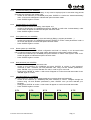
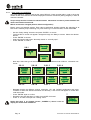
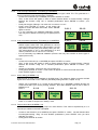
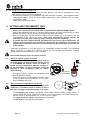
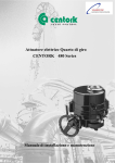
Digital electric actuator
CENTORK 460 Series
Installation and maintenance
user’s manual
INDEX
1.
2.
3.
CENTORK ELECTRIC ACTUATORS .....................................................................................................3
SAFETY INSTRUCTIONS.......................................................................................................................3
TRANSPORT AND STORAGE ...............................................................................................................3
3.1
Transport..............................................................................................................................................3
3.2
Storage.................................................................................................................................................3
4.
SERVICE conditions FOR ELECTRIC ACTUATORS.............................................................................4
4.1
Electric actuator: Main description and purpose..................................................................................4
4.2
Temperature range ..............................................................................................................................4
4.3
Actuator and motor duty service ..........................................................................................................4
4.4
IP protection degree.............................................................................................................................4
4.5
Painting and protection against corrosion............................................................................................4
4.6
Electronic features ...............................................................................................................................4
5.
MOUNTING TO THE VALVE ..................................................................................................................6
5.1
Pre-Installation Inspection....................................................................................................................6
5.2
Output size ...........................................................................................................................................6
5.3
Output type...........................................................................................................................................6
5.4
Mounting: .............................................................................................................................................6
6.
MANUAL OPERATION ...........................................................................................................................6
7.
ELECTRIC AND ELECTRIC CONNECTIONS........................................................................................7
7.1
Wiring diagram (electric manoeuvre) ...................................................................................................7
7.2
Terminal plan and wiring......................................................................................................................7
8.
FRONTAL INTERFACE ..........................................................................................................................8
8.1
Torque and position control and measurement electronic Unit ...........................................................8
8.2
Menu routines and screens..................................................................................................................8
8.3
Main menu ...........................................................................................................................................9
8.4
Operational Data submenu (SCREEN 4) ............................................................................................9
8.5
Settings (SCREEN 2).........................................................................................................................10
9.
SETTING AND PRELIMINARY TEST...................................................................................................14
9.1
Sense of rotation actuator and valve .................................................................................................14
9.2
Motor and power supply (Sense of rotation)......................................................................................14
9.3
Closed position limit switch setting ....................................................................................................15
9.4
Open position limit switch setting.......................................................................................................15
9.5
Close Torque switching setting ..........................................................................................................15
9.6
Open Torque switching setting ..........................................................................................................15
9.7
Intermediate limit switches.................................................................................................................15
9.8
4-20 mA Position transmitter (OPTIONAL): TPS...............................................................................15
10.
MAINTENANCE.....................................................................................................................................16
10.1
After commissioning .......................................................................................................................16
10.2
Maintenance for service .................................................................................................................16
10.3
Electric actuator’s service life .........................................................................................................16
10.4
Batteries .........................................................................................................................................16
11.
TECHNICAL SUPPORT........................................................................................................................17
12.
APPENDIX.............................................................................................................................................17
CAUTION: CENTORK electric actuators are a high value devices. In order to prevent damage
in their handling, setting and use it is essential to follow and observe all the points in this
user manual, operate under actuators’ designated use, and observe health and safety rules,
standards and directives, as other national regulations as well.
CENTORK electric actuators must be handled with care and caution.
IMPORTANT NOTE
The contents in this manual is subject to change due to the quality improvement, without
individual notice.
ELECTRIC ACTUATOR USER MANUAL
Pag 1
Pag 2
ELECTRIC ACTUATOR USER MANUAL
1. CENTORK ELECTRIC ACTUATORS
The electric actuator is a device designed to be coupled to a general purpose industrial valve to carry out
its movement. The movement is stopped by limit switching or by torque (thrust) switching.
2. SAFETY INSTRUCTIONS
The scope of this manual is to enable a competent user to install, operate, adjust and inspect a
CENTORK electric actuator. These instructions must be observed, otherwise a safe operation of the
actuator in no longer warrantee.
As electric device, during electrical operation certain parts inevitably carry lethal voltages and
currents (ELECTRICAL RISKS). Work on the electrical system or equipment must only be
carried out by a skilled electrician himself or by specially instructed personnel, in accordance
with the applicable electrical engineering rules, health and safety Directives and any other
national legislation applicable.
Electric actuator devices are a high powerful apparatus. A negligence handling might cause
severe damages to valves, people, and actuator as well. Under no circumstances should any
modification or alteration be carried out on the actuator as this could very well invalidate the
conditions which the device was designed.
3. TRANSPORT AND STORAGE
3.1
Transport
−
−
−
3.2
CENTORK electric actuators must be transported in sturdy packing. During transport measures
should be adopt in order to prevent impacts, hits. CENTORK delivers its actuators ex-work.
Hits or impacts against wall, surfaces or objects might cause severe damage on electric actuator.
In this cases, after such events, a technical inspection must be done by CENTORK technicians.
Do not attach to the handwheel ropes or hooks to lift by hoist.
Storage
−
−
−
−
−
−
−
−
Store in a clean, cool, dry and ventilated place. For other storage conditions or, and long
time periods (More than 5 months) contact to manufacturer.
Check that electrical connection cover and switching and signalling unit cover and are correctly
closed ant tight.
Cable entries on electrical connection cover must be sealed. Protection plug supplied by
CENTORK are only adequate for storing in dry and ventilated places, for short period of time. In
other conditions protection plug must be replaced with metallic plug sealed with PTFE tape.
Do not store the actuator directly on the ground!
Cover it to protect it from dust and dirt. Cover the machined parts with suitable protection against
corrosion.
Do not handle it by picking it up by the handwheel.
Just when commissioning, CENTORK recommend a visual inspection in order to detect any
anomaly caused during the transport, and during the storage as well. Checking should
include a visual inspection of electric compartment, and switching and signalling unit
shouldn’t be opened .
For further details, consult the technical sheet ‘Conditions for Transport and Storage’.
ELECTRIC ACTUATOR USER MANUAL
Pag 3
4. SERVICE CONDITIONS FOR ELECTRIC ACTUATORS
4.1
Electric actuator: Main description and purpose
−
−
−
−
−
Electric actuator is an apparatus or device formed by a electric motor, coupled to a main gearbox
unit, which transmits motion and torque to valves. An electronic unit formed by electronic boards
and sensors, inside of electric actuator, allows to provide continuous torque measurement and
control, and continuous position measurement and control.
Electronic device actives settable output relays which allows torque and limit switching operation.
Limit and torque switches relays must be included on the electric manoeuvre in order to
prevent overloads on valve and actuator which might cause a fatal damage on valve and
actuator, Electric motor are powerful devices.
Electric actuators series 460 can be operated using an external electric cabinet, or employing
CENTRONIK units. For more information, consult CENTORK.
Electric actuators actuators are provided with a declutchable manual override system in order to
operate manually in case of emergency or fail of oil supply.
Electric actuator can be coupled directly to valve, or maybe, through gearbox units (Bevel, spur
and worm gearboxes)
4.2
Temperature range
CENTORK electric actuators work in a temperature range from -25ºC to +70ºC.
4.3
Actuator and motor duty service
−
−
−
−
4.4
IP protection degree
−
4.5
CENTORK electric actuators are designed in their standard version with IP67 (acc. EN 60.529)
environmental protection although IP68 protection may be supplied on request. IP67 and IP68
protection degree is only guarantee employing proper protection plug and cable gland for
cable entries, according to IP degree (See chapter 7) . It is necessary to observe storing and
maintenance rules written on chapter 10 as well.
Painting and protection against corrosion
−
−
4.6
Electric actuator series 460 have been designed for valve motorization which requires ON-OFF
and inching (Modulating) duty service.
Electric actuator can run continuously at nominal torque. Nominal torque is rated to 50% of max
tripping torque (100%), value marked on actuator nameplates. Higher nominal torques can reduce
the actuator’s service life.
Max torque is only recommended for short period of time, not exceeding 10% of total operation
time.
Electric motor has been designed to operate under severe conditions. Motors have been designed
for S2 short duty and S4 modulating duty. For more technical details, contact CENTORK.
As standard, CENTORK has designed three protection degree: Standard protection, P1 and P2.
For technical details, consult CENTORK.
Electric actuator are coated with a epoxy- two components primer (Film thickness depends on
protection class selected, actuators are coated with intermediates primers) followed by a
polyurethane component paint coat. The standard colour is blue RAL 5003. Other colours are
possible (Option). Other film thickness under request.
Electronic features
−
Local indication: A LCD display 48 character control panel including the following information:
− Valve position and Torque (Percentage)
− Actuator status (Outputs relays)
− Serial number
− Operations Data (Recorder):This menu indicates the number of the following
information: Opening Operations, Closing operations, Open torque Faults, Close torque
faults, Thermal faults, Number of cycles,
− Settings menu: Menu Protected by password. Adjust the following data:
− Set Open Position 0% (Adjust the close position)
Pag 4
ELECTRIC ACTUATOR USER MANUAL
−
−
−
−
−
−
−
Set Open position 100% (Adjust the open position)
Open Torque Value (Adjust the Open torque value for torque switching)
Close Torque Value (Adjust the Close torque value for torque switching)
Intermediate limit switching (Adjust middle travel, %; limit switch)
Alarm settings
TPS setting: Adjust of analogue position transmitter: 4/20mA or0/20 mA, direct or
reverse polarity
− TTS Setting: Adjust of analogue position transmitter: 4/20mA or0/20 mA, direct or
reverse polarity
− Relays setting: 4 relay configurable, 7 relays as option.
− Language setting : English, Spanish, German, French and Italian. Other languages
under request.
Four LED for main indication:
− Red/green LED indicator (LED1 and LED4): Red “ON”: Valve fully opened / Green
“ON”: Valve fully closed
− Red LED indicator (LED2): Red “ON”: Alarm activated
− Yellow LED indicator (LED3): Yellow “ON”: Valve in intermediate position
−
Position control:
− A position encoder, incorporated in the actuator, design permits continuous monitoring
of valve position during motor and hand wheel operation.
− The calibration may be done with the control panel.
− Maximum allowable actuator stroke= 100.000 turns (Output shaft)
−
Torque Control:
− Two force sensors, incorporated in the actuator PTCS, allows continuous monitoring of
valve torque during motor an hand wheel operation.
− Tripping torque can be adjusted from 40% up to 100% of maximum Torque,
(According to electric actuators range) independent for each rotation sense (Open and
close).
−
Motor thermal protection: The motor is protected against overheating by thermistors embedded in
the motor windings.
−
Position and Torque switch: 4 programmable Bistable relays, 24VDC/250VAC (Standard) and up
to 11 programmable relays (Optional)
−
Position and torque analogue transmitters TPS and TTS (Optional):
− TPS Analogue position transmitter (2 wire 0/20mA o 4/20mA programmable).
− TTS Analogue Torque transmitter (2 wire 0/20mA o 4/20mA programmable)
− Both sensor receive supplied from internal voltage source.
−
Serial communication (Optional): Serial communication RS232, permit to read/write all the data of
the actuator, for setting and maintenance facilities.
ELECTRIC ACTUATOR USER MANUAL
Pag 5
5. MOUNTING TO THE VALVE
5.1
Pre-Installation Inspection
−
Verify the actuators nameplate to insure correct model number, torque, operating speed, voltage and
enclosure type before installation or use.
−
It is important to verify that the output torque of the actuator is appropriate for the torque
requirements of the valve and that the actuator duty cycle is appropriate on the intended application
5.2
Output size
Check whether actuator output flange suits the flange of the valve to be driven. The latter should have
been designed following the ISO5210 or ISO5211 standard, for standard application, or following the
customer’s specifications, for special application.
5.3
Output type
Check that the type of flange-coupling of the actuator suits the valve to be driven (diameters and
lengths). Those manufactured as Standard at CENTORK follow the ISO5210/5211 standards. Types
of output drive:
−
−
−
5.4
Output type A: If not otherwise specified in the order, it is supplied blank. The thread must be
machined according to the stem of the valve to be driven. For the dismounting and machining of
this type of output, see Appendix . Output type A models can withstand axial loads and torque
Output type B1, B2, C: It is supplied machined to the dimensions stated in the ISO 5210/5211 or
DIN 3338 standard. Output type B and C models cannot withstand axial loads.
Output type B3, B4: It is supplied blank. For the dismounting and machining of this type of output,
see Appendix .
Mounting:
−
−
−
−
−
−
−
Once the size and the type of output match the valve to be driven, we can go on to the following
step.
Degrease the mounting surfaces at actuator and valve thoroughly.
Slightly grease the input shaft of the valve to be driven.
Fit the actuator into the valve. In the event of a threaded output (type A), use the handwheel for
turning the nut over the threaded stem.
Do not lift the actuator by the handwheel
The actuator may be mounted in any position
Using ISO Class 8.8 quality bolts, fasten crosswise controlling the applied torque according to the
table in Appendix
6. MANUAL OPERATION
−
−
−
CENTORK actuators are fitted with a handwheel for the manual actuation of
the valve.
In the case of simultaneous motorised and manual working, the motorised one
will always be the preferential one.
Once the handwheel has been engaged is not possible to disengaged, the
override engagement lever returns automatically to motor position when
the motor is operated.
Engagement of manual operation:
− Turn the change-over lever 20º clockwise while slightly turning the handwheel.
− When you notice an increase in the resistance of the wheel, the manual control
is engaged.
− Run the valve in the desired direction. Standard sense of rotation is clockwise
to close. For greater operating speed you can connect any powertool,
pneumatic or electric, to the hand-wheel shaft. The maximum speed is 150
rpm.
Pag 6
Movement
Handwheel
ELECTRIC ACTUATOR USER MANUAL
7. ELECTRIC AND ELECTRIC CONNECTIONS
CAUTION:
When handling electric equipment, take into account the health and safety standards (EN
60204, 73/23/EEC directive) and any other national legislation applicable.
7.1
Wiring diagram (electric manoeuvre)
Electric actuator must be controlled by a external electric cabinet with all elements needed
(Transformer, contactors, relays, lamps, fuses…) Wiring diagram should be designed according to
electric actuator features. Electric actuator datasheet, supplied with the actuator, includes a
PROPOSED WIRING DIAGRAM, delivered with other technical documentation.
The following points should be observed:
−
−
−
−
−
We recommend to switch off the corresponding contactor/relay always directly by the limit or
torque RELAYS (opening and closing). Torque RELAYS must be included on Electric/electric
manoeuvre in order to protect actuator and valve from undesired overloads. Each valve
manufacturer decides whether the switching off at both ends is made by torque switching
(RELAYS) or by limit switching (RELAYS). Electric features of RELAYS are included on appendix.
The maximum delay for switching off the motor with the signal of the torque or limit RELAY
cannot exceed 40 ms.
Torque RELAY signals are non-maintained signals, when motor stops after a over-torque
condition torque signals may reset (Non-maintained). Relays or another device must be
employed (See wiring diagram on APPENDIX)
Capacitors for single-phase A.C. motors are delivered with electric actuators. They should be
installed on electric cabinet (External). Each capacitor is dimensioned according to motor voltage
and power.
CENTORK actuators are provided with thermo-switches mounted in the windings of the motor
(TRM). The protection of the motor is only achieved with a proper connection for these
thermostats. Centork guarantee for the motor is not valid if this connection is not properly
done. DC motor do not have thermo-switches on windings. Max current should be limited.
Features of electric and electronic components listed on appendix. Wiring diagram are included on
appendix: D0105X1 for A.C. three-phase, D0107X1 for A.C. single-phase.
7.2
Terminal plan and wiring
The electric connection diagram or terminal plan is depicted on Electric actuator datasheet,
supplied with the actuator, and it can be found printed on a label inside of electrical
compartment cover.
− Open the electrical cover
− Feed the cable(s) through the cable glands . Fix proper cable glands according to IP67 or IP68
protection degree.
Figure 6.1
Figure 6.2
Figure 6.3
Figure 6.4
Electric actuator with Plug-socket connectors with screws
− Unscrew the attachment plate from the connection cover.
− With a suitable screwdriver, connect the cables for the control signals according to the electric
connection diagram. (Figure 6.1)
ELECTRIC ACTUATOR USER MANUAL
Pag 7
Electric actuator with Terminals connection
− With a suitable screwdriver (SD 0,6x3,5 DIN 5264-A), connect the cables for the control signals
according to the electric connection diagram. (Figure 6.2 and Figure 6.4)
CAUTION:
−
−
−
to the earth connection located
Connect the earth cable terminal
inside of electric connection cover (M5 screw hole). Electric actuator has
a external bolt in order to connect an external earth terminal.
Once you have checked that the connections have been properly carried
out, close the connection cover and check the proper connection, the
state of the o-ring seal and the proper installation of the latter, greasing it
slightly. Fasten the 4 screws crosswise.
Fix proper cable glands according to IP67 or IP68 protection
degree. Replace the protection plug with suitable metallic
protection plug sealed with PTFE . (Figure 6.3) Tighten cable glands
and protection plugs to ensure enclosure IP67 (IP68 if applicable).
WARNING!
REPLACE WITH
METAL PLUG
SEALED WITH
PTFE TAPE
8. FRONTAL INTERFACE
LCD
DISPLAY
“SCAPE”
pushbutton
“ENTER”
pushbutton
8.1
INDICATION LEDS
“UP”
pushbutton
“DOWN”
pushbutton
Torque and position control and measurement electronic Unit
The figure depicts the frontal interface of the DIGITAL electric actuator. It is not necessary to open the
frontal panel during the first years. For main maintenance and stat-up routines user don not need to
open this cover. CENTORK recommend no to do it, in order to keep the Protection degree (Sealing).
For batteries changes, and battery description see chapter 10.4.
8.2
Menu routines and screens
A LCD display allows user to set and communicate with the actuator. Two
categories can be found:
− Main menu
− Settings and Operational data submenus
screens or menus
.
Pag 8
ELECTRIC ACTUATOR USER MANUAL
8.3
Main menu
Pressing “UP” and “DOWN” pushbuttons, user can
access to different information.
1
2
3
8.4
5
6
7
4
Operational Data submenu (SCREEN 4)
−
−
−
Pressing “UP” and “DOWN” pushbuttons navigate
thought main menu screen until “Settings” screen is
selected.
Then press “ENTER” to confirm and get into setting
menu.
Navigate through screens to access to information:
4.1
4.2
4.7
−
4.3
4.6
4.4
4.5
Press “ESCAPE” to return to Main Menu
ELECTRIC ACTUATOR USER MANUAL
Pag 9
8.5
Settings (SCREEN 2)
−
−
−
−
−
Pressing “UP” and “DOWN” pushbuttons navigate thought main menu screen until “Settings”
screen is selected
Then press “ENTER” to confirm and get into setting menu.
A password screen will appear. User should introduce the password number. Default password
code is 0123. User can change this password code.
Pressing “UP” and “DOWN” select the first code or digit. Then press
“ENTER” to confirm. Automatically the second code or digit will flash or
blink, waiting for confirmation or change. Select the second code
Repeat this steps until the complete code is introduced.
Wrong codes causes that program automatically escapes to main menu. If user makes a mistake in
one code, it is not possible to go back. It is necessary to escape and enter again to “Settings” menu.
Setting menu is formed by several submenus, explained in following chapters.
2.1
2.13
2.2
2.3
2.4
2.12
2.5
2.11
2.10
8.5.1
2.9
2.8
2.7
2.6
Set open position 0% (2.1 SCREEN):
This menu allows to set the Open position 0% (Valve Fully close) and 100% (Valve fully open)
− Run the valve to the desired close position (0%), electrically or
manually –via handwheel-. Notice that when running, INDICATOR
LAMPS will light on and off. That means that position sensor is working
correctly. If user reverse the movement, colour sequence will reverse
too.
− Keep pressing for 5 seconds “ENTER” pushbutton. After that, a OK message will appear. Press
“ENTER” again to confirm.
Program will show a new screen: Setting open position 100% (Valve Fully open)
−
−
Run the valve to the desired open position (0%), electrically or manually –via handwheel-. Notice
that when running, INDICATOR LAMPS will light on and off, as well.
Keep pressing for 5 seconds “ENTER” pushbutton. After that, a OK message will appear. Press
“ENTER” again to confirm.
Pag 10
ELECTRIC ACTUATOR USER MANUAL
8.5.2
Desactivate Battery (2.2 SCREEN)
This menu allows to desactivate the battery. It only must be employed just in case when long periods
of storage are expected. See chapter 10.4
− Access to this submenu (2.2 SCREEN) and press “ENTER” to confirm the “desactivate battery”
order. A OK screen will appear to indicate that option has been made.
− Press “ENTER” again to confirm.
8.5.3
Activate Battery (2.3 SCREEN)
This menu allows to activate the battery. See chapter 10.4
− Access to this submenu (2.3 SCREEN) and press “ENTER” to confirm the “Activate battery” order.
A OK screen will appear to indicate that option has been made.
− Press “ENTER” again to confirm.
8.5.4
Store parameter (2.4 SCREEN)
This menu allows to store in memory the actual settings (Relays, program parameters…)
− Access to this submenu (2.4 SCREEN) and press “ENTER” to confirm “Store parameters” order. A
OK screen will appear to indicate that option has been made.
− Press “ENTER” again to confirm.
8.5.5
Reset system (2.5 SCREEN)
This menu allows to recover the default configuration and load it in memory. It can be useful when
many undesired changes have been made. Notice that previous configurations will be erased!
− Access to this submenu (2.5 SCREEN) and press “ENTER” to confirm “reset system” order. A OK
screen will appear to indicate that option has been made.
− Press “ENTER” again to confirm.
8.5.6
New password (2.6 SCREEN)
This menu allows to change the password code.
− Access to this submenu (2.6 SCREEN) and press “ENTER” to confirm a “new password”
command or order. Introduce your new password code, using “UP and “DOWN” pushbuttons,
press “ENTER” once you have selected one code, in order to go to next code.
− Finally press “ENTER” to confirm. A OK screen will appear to confirm that order was made. Press
“ENTER” again to confirm.
8.5.7
Language setting (2.7 SCREEN)
This menu allows to change the language employed on screens (texts and message).
− Access to this submenu (2.7 SCREEN) and press “ENTER” to confirm. Navigate thought the
screens using “UP and “DOWN” pushbuttons, press “ENTER” once you have selected your
language.
− Finally press “ENTER” to confirm. A OK screen will appear to confirm that order was made.
− Press “ENTER” again to confirm.
2.7.1
2.7.2
ELECTRIC ACTUATOR USER MANUAL
2.7.3
2.7.4
2.7.5
Pag 11
8.5.8
Relay setting (2.8 SCREEN)
This menu allows to configure and set the output RELAYS. Check terminal plan in order to know the
number of RELAYS. RELAYS should be employed on electric manoeuvre (Wiring diagram) in order to
control the actuator.
Torque relays must be included on electric/electric manoeuvre in order to protect actuator and
valve from undesired overloads.
RELAY 5 cannot be changed (It has a default configuration)
Electric motor are powerful devices. Each valve manufacturer decides whether the switching off at
both ends is made by torque switching or by limit switching. For technical data, consult CENTORK.
−
−
−
−
−
Get into “Relay setting” submenu and press “ENTER” to access.
The first RELAY screen will appear. Navigate through the Relay’s screens. Select the desired
RELAY.
Press “ENTER” to access.
Select and set the relay state: “Normally closed” or “normally open”.
Press “ENTER” to confirm.
2.8.1
−
−
−
−
−
Next step: Select the type of information for the RELAY: Different kind of RELAY information can
be set:
2.8.1.1
2.8.1.2
2.8.1.3
2.8.1.4
2.8.1.5
2.8.1.6
2.8.1.7
2.8.1.8
Navigate thought the different screens, employing “UP” and “DOWN” pushbuttons and press
“ENTER” to select the desired information for this relay. A OK screen will appear to confirm that
order was made.
Press “ENTER” again to confirm.
7
Repeat the process described, in order to set all RELAYS used.
Press “C” in order to escape from “Setting” menu.
Notice that there is an Outputs screen ( SCREEN 7) where it can be
display the actual state of RELAYS
Pag 12
ELECTRIC ACTUATOR USER MANUAL
8.5.9
−
−
−
−
−
4-20 mA torque transmitter: TTS setting (2.9 SCREEN)
This menu allows to set and configure the 4-20 mA torque signal, called TTS. TTS generates a 420 mA continuous signal proportional to TORQUE.
Access to this submenu (2.9 SCREEN) and press “ENTER” to confirm.
Then, a new screen will appear in order to select between Direct or reverse Polarity. Change
between this screens, using “UP” or “DOWN” pushbuttons, press “ENTER” to confirm your
choice.
Finally set the type of Range: 4-20 mA/2-10V or 0-20 mA / 0-10 V.
Finally press “ENTER” to confirm. A OK screen will
appear to confirm that order was made. Press “ENTER”
2.9.1.1
2.9.1.2
again to confirm.
It is not necessary any additional calibration process.
User only has to define or set the type of signal (Volts or
mA).
8.5.10 4-20 mA position transmitter: TPS setting (2.10 SCREEN)
−
−
2.9.2.1
2.9.2.2
This menu allows to set and configure the 4-20 mA
position signal, called TPS. TPS generates a 4-20 mA
continuous signal proportional to valve position. As limit
end position CLOSE (0%) and OPEN (100%) are set,
TPS automatically is set or auto-calibrated to its end
values (4-20mA/2-10V or 0-20 mA or 0-10Volts).
It is not necessary any additional calibration process. User only has to define or set the type of
signal (Volts or mA).
Process:
− Access to this submenu (2.10 SCREEN) and press “ENTER” to confirm.
− Then, a new screen will appear in order to select between Direct or reverse Polarity. Change
between this screens, using “UP” or “DOWN” pushbuttons, press “ENTER” to confirm your
choice.
− Set the type of Range: 4-20 mA/2-10V or 0-20 mA/0-10 V.
− Finally press “ENTER” to confirm. A OK screen will appear to confirm that order was made.
− Press “ENTER” again to confirm.
8.5.11 Alarm setting (SCREEN 2.11)
Different kind of event can be defined as ALARM signal. This submenu allows to set the ALARM
signal which actives ON or OFF a RELAY (See Relay setting submenu, chapter 8.5.8).
−
Alarms can be activated or no. Access to this submenu (2.11 SCREEN), navigate through the
screens and select your choice pressing “ENTER”, then select between YES or NO in order to
activate or not.
2.11.1
−
2.11.2
2.11.3
2.11.3.1
Press “C” in order to escape from “Setting” menu.
8.5.12 Torque close value (SCREEN 2.12)
This menu allows to set the tripping torque for close direction. This value is expressed by a % of
rated torque marked on actuator nameplate.
−
−
Access to this submenu (2.12 SCREEN) and press “ENTER” to confirm. Set the desired value
increasing/decreasing, using “UP and “DOWN” pushbuttons, press “ENTER” once you have
selected your value.
Finally press “ENTER” to confirm.
ELECTRIC ACTUATOR USER MANUAL
Pag 13
8.5.13
Torque open value (SCREEN 2.13)
This menu allows to set the tipping toque for open direction. This value is expressed by a % of
rated torque marked on actuator nameplate.
− Access to this submenu (2.13 SCREEN) and press “ENTER” to confirm. Set the desired value
increasing/decreasing, using “UP and “DOWN” pushbuttons, press “ENTER” once you have
selected your value.
− Finally press “ENTER” to confirm.
9. SETTING AND PRELIMINARY TEST
−
−
−
−
Safety rules and standard should be observed (See SAFETY INSTRUCTIONS chapter)
Setting and preliminary test can only be done when finished the wiring and mounting on valve.
Electric and electric manoeuvre and devices should be ready and checked.
Both the torque and the limit switches setting must be carried out in accordance with the
characteristics of the valve to be driven. Each valve manufacturer decides whether the
switching off at both ends is made by torque switching or by limit switching.
If actuator has been supplied already assembled onto the valve by valve manufacturer, the
settings made originally by the manufacturer should NOT be modified on site without the
authorisation of the latter, otherwise, serious damage may be caused both to the valve and
to the actuator.
CENTORK recommend to move the valve to an intermediate position manually, -via handwheel
device- (according to chapter 6) in order to execute the test routines descried below, avoiding
problems due to incorrect routines or user’s mistakes.
User should not open covers for setting routines!
9.1
Sense of rotation actuator and valve
Electric actuator and valve sense of rotation must be
the same. Electric actuator sense of rotation criteria
is CLOCKWISE TO CLOCK. Sense of rotation is
critical for many components (RELAYS, sensors, 420 mA transmitter). A correct operation cannot be
warranty in case of different sense of rotation
valve/actuator)
−
−
9.2
Operate the electric actuator via handwheel (See
Manual operation chapter).
Check that running the handwheel clockwise, valve
moves to close. If the turn direction is not correct,
stop immediately and verify.
CLOSE
Movement
CLOCKWISE
Motor and power supply (Sense of rotation)
When running to close, electric actuator output shaft
should turn in clockwise sense of rotation as well. It
this does not happen, stop immediately!, and check:
−
−
−
For three-phase A.C. motors: Check that U-V-W phase sequence (Main voltage supply) is
correct. Notice that U-V-W phases are wired to 1-2-3 motor contacts or terminals. Change two
phases U-V-W on terminal blocks (e.g. U and V) and try it again.
For single-phase A.C. motors: Verify the wiring (See figure)
For DC motors: Check polarity on terminals!.
Pag 14
ELECTRIC ACTUATOR USER MANUAL
9.3
Closed position limit switch setting
−
−
−
−
9.4
Manually or electrically operate the valve to the desired CLOSED position.
Access to “Settings” menu (See chapter 8.4)
Access to “Set open position 0%” menu and set the “FULLY CLOSE” limit position (See chapter
8.4.1)
Check that when opens, RELAY corresponding to “Reached position close” is switches off. (See
Data operation menu, outputs submenu), also, INDICATOR LED will light off. Then go back to
“fully close” position and check that Relay “Reached position close” switches on and INDICATION
LED (nº4) lights on (GREEN).
Open position limit switch setting
−
−
−
−
Manually or electrically operate the valve to the desired OPEN position.
Access to “Settings” menu (See chapter 8.4)
Access to “Set open position 100%” menu and set the “FULLY OPEN” limit position (See chapter
8.4.1)
Check that when closes, RELAY corresponding to “Reached position open” switches off. (See
Data operation menu, outputs submenu), also, INDICATOR LED will light off. Then go back to
“fully open” position and check that Relay “Reached position open” switches on and INDICATION
LED (nº1) lights on.
9.5
Close Torque switching setting
CENTORK electric actuators leave the factory tested and calibrated for its Max. Torque (100%) rated
on nameplates, as standard.
Guarantee is not valid if the user exceeds 100%, or if torque RELAYS are not employed on
electric manoeuvre.
− Access to “Settings” menu (See chapter 8.4)
− Access to “Torque close value” (SCREEN 2.12) and set the Torque value (%). Warning! Consult
valve manufacturer for Thrust and torque allowable on valve!
9.6
Open Torque switching setting
CENTORK electric actuators leave the factory tested and calibrated for its Max. Torque (100%) rated
on nameplates, as standard.
Guarantee is not valid if the user exceeds 100%, or if torque RELAYS are not employed on
electric manoeuvre.
− Access to “Settings” menu (See chapter 8.4)
− Access to “Torque open value” (SCREEN 2.13) and set the Torque value (%). Warning! Consult
valve manufacturer for Thrust and torque allowable on valve!
9.7
Intermediate limit switches
Electric actuator allows to set two intermediate signals (RELAYS). These positions can be set, as a
percentage of total stroke (%)
− Access to “Settings” menu (See chapter 8.4)
− Access to “Relays settings” (SCREEN 2.9), select the proper “RELAY”, and set “Intermediate
position 1” or “Intermediate position 2”. Set the % position employing “UP” and “DOWN”
pushbuttons.
9.8
4-20 mA Position transmitter (OPTIONAL): TPS
As limit end positions (Valve fully OPEN and valve fully CLOSED) are set, TPS values (4-20 mA, or 020 mA or 0-10 Volt, see chapter 8.5.10) are auto-adjusted or calibrated according to those end of
travel limits . They do not depend on valve stroke, number of turns.
ELECTRIC ACTUATOR USER MANUAL
Pag 15
10. MAINTENANCE
CENTORK actuators are supplied greased from the factory for their lifetime, needing practically no
maintenance.
10.1 After commissioning
−
−
−
Check for damage on paint caused by transport, assembly or handling and repair the damage
carefully in order to ensure complete protection against corrosion.
Make sure that all the o-ring seals are correctly mounted and that the cable glands are firmly
fastened , and protection plug for cable entry not used have been replaced with metallic protection
plug sealed with PTFE tape, in order to ensure the IP67, IP68 protection.
The most important condition for reliable service of the CENTORK actuators is the fact of having
carried out a correct commissioning and set-up procedure.
10.2 Maintenance for service
CENTORK recommends for a preventive maintenance programme: Approximately 3 months after
commissioning and then every 9/12 months:
− Check the correct tightening of the bolts between the actuator and the valve. Retighten according
to section 2 if required.
− Take advantage of each revision to check the proper tightening of the covers, of the handwheel
lock and the external electric connection.
− Check cable entries
− Visual inspection inside of switching and signalling, and electrical compartments.
− Contact with valve manufacturer I order to know about maintenance routines of valve.
In the event of infrequent service, perform a test run every 6 months in order to ensure the availability
of service of the actuator.
10.3 Electric actuator’s service life
−
−
−
−
Electric actuator service life is rated to 20.000 cycles.
Each cycle is formed by an opening manoeuvre (Valve close position to valve open position) and a
closing manoeuvre (Valve open position to valve close position).
50 turns has been considered as standard valve stroke reference.
Operation data screen allows to check the number of cycles made.
10.4 Batteries
Torque and position control and measurement electronic unit has been designed with a very low
energy consumption.
When main voltage is not supplied, electronic unit remains in a STAND BY state. Main screen will turn
off, and INDICATION LEDS will light off, as well. Electronic unit will measure any change of valve
position (E.g. operating manually –via handwheel-).
Electronic unit will check the battery level. Checking routines are
made every 30 minutes. Low levels are indicated on screen
employing a “battery symbol”. In that case, connect to main power
supply or replace battery. Batteries life is rated on 4 operation
years, as average.
Replacing batteries:
− Battery is located inside of NON-INTRUSIVE frontal
interface. Open this cover carefully , taking care of
wires, and replace the battery. In some cases, it will
be necessary to dismount some electronic boards in
order to access to battery. In that case, once the
battery has been replace, reconnect all wires.
− Employ only CENTORK Battery spares!!
Pag 16
ELECTRIC ACTUATOR USER MANUAL
11. TECHNICAL SUPPORT
Each actuator is supplied with a datasheet on A4 format. The following is included:
− The nameplates attached to the actuator.
− The electric connection diagram for each actuator (also stuck inside the connections cover of the
actuator).
For any claim or information request, the SERIAL NUMBER included on this datasheet or on the electric
actuator nameplates should be used.
Electric actuator manufacturer address: See on Manual covers.
12. APPENDIX
− OUTPUT TYPES
− FASTEN BOLTS (CLASS 8.8)
− WIRING DIAGRAMS, TERMINAL PLANS, LEGENDS AND SYMBOLS.
− D0105X1 DIAGRAM
−
D0107X1 DIAGRAM
ELECTRIC ACTUATOR USER MANUAL
Pag 17
OUTPUT TYPES
OUTPUT TYPE A Size F-07 (ISO 5210)
Disassembly:
Employing a suitable tool, remove the retaining ring (3) which fix
the removable bronze bush (1).
Push in order to extract this piece.
Assembly:
Having machined the removable bush according to valve stem
dimensions, refit the drive bus (1) into the output shaft bore, align
the keyway (2) in its output shaft shape.
Refit the retaining ring (3).
Figure 1
OUTPUT TYPE A Size F-10/F-16/F-25 (ISO 5210)
Disassembly:
Push and press the removable bronze bush (2) in order to extract
the cover (4), axial bearings (3) and removable bronze bush (2)
Assembly:
Having machined the removable bronze bush according to valve
shaft, clean toughly this piece. Apply grease on axial bearings and
discs (3). Assemble axial disc on removable bush (2), finally insert
the cover (4). Check O-rings on cover.
Apply grease on. Insert the removable bush on output type A
base casting unit and output shaft, notice that dog coupling
(Tooth) on bushing should match with actuator hollow output shaft
(1).Verify O-ring (4).
Figure 2
For maintenance, grease can be supply thought grease nipple (5).
Pag 18
ELECTRIC ACTUATOR USER MANUAL
OUTPUT TYPE A Size F-14 (ISO 5210)
Disassembly
− Remove retaining ring (5) and unscrew the stop ring
(4) employing a suitable tool.
− Push and press the removable bronze bush (1) in
order to extract it.
Assembly:
− Having machined the removable bush according to
valve stem dimensions, refit the drive bus (1) into the
output shaft bore (3), align the keyway (2) in its output
shaft shape.
− Screw the stop ring (4) employing a suitable tool.
− Refit the retaining ring (5).
Figure 3
OUTPUT TYPE B3 Size F-07/F-10/F-14/F-16/F-25
(ISO 5210)
Disassembly:
−
−
Employing a suitable tool, remove the retaining ring
(4) which fix the removable steel bush (1).
Push in order to extract this piece.
Assembly:
−
−
Having machined the removable steel bush according
to valve stem dimensions, refit the drive bus (1) into
the output shaft bore, align the keyway (2) in its output
shaft shape.
Refit the retaining ring (4).
Figure 4
OUTPUT TYPE B0 Size F-10 / F-14
B0 output type is supplied, already machined, according to
dimensions published in technical datasheets.
Disassembly:
−
−
Employing a suitable tool, remove the retaining ring
(3) which fix the removable steel bush (1).Removable
bush is located inside of output shaft (2)
Push in order to extract this piece.
Assembly:
−
−
Figure 5
Having machined the removable steel bush according
to valve stem dimensions, refit the drive bus (1) into
the output shaft bore
Refit the retaining ring (3).
ELECTRIC ACTUATOR USER MANUAL
Pag 19
FASTEN BOLTS (CLASS 8.8)
FRICTION FACTOR
BOLT
LOW
MEDIUM
HIGH
M4
4.2
6
8
M6
6.2
8.2
10
M8
15
21
24
M10
30
41
48
M12
49
68
85
M14
85
108
130
M16
130
165
200
M18
170
240
280
M20
240
340
410
M30
800
1150
1350
M36
1450
2050
2400
Torque values in N.m
Steel bolts class 8.8
Pag 20
ELECTRIC ACTUATOR USER MANUAL
WIRING DIAGRAMS, TERMINAL PLANS, LEGENDS AND SYMBOLS
SYMBOL
M
DESCRIPTION
TECHNICAL FEATURES
−
−
−
−
MOTOR:
A.C. motor (single and three-phase)
SUPPLY SOURCE:
120v
Supply source (Voltage) for Torque and
230v
position control and measurement electronic 446v
unit
Squirrel cage motor.
Isolation class F.
Main power supply: See motor nameplates.
Main voltage supply tolerance: ±5%
(±18%) 50/60Hz
(±14%) 50/60Hz
(±23%) 50/60Hz
RELAY:
Switching rating (Imax) for 250VAC: 10A ( cosφ=1)
Switching rating (Imax) for 30VDC: 10A (resistive load)
BLK:
Movement signalling unit (Blinker).
Type: Transistor
Voltage: 24VDC
Max current: 100mA
TPS:
Electronic Position transmitter
2 wire active system
Maximum load for current transmisor: 500Ω
Minimum load for tension transmisor: 1000 Ω
TTS:
Electronic Torque transmitter
2 wire active system
Maximum load for current transmisor: 500Ω
Minimum load for tension transmisor: 1000 Ω
For further technical information, consult CENTORK technical datasheet or contact directly with CENTORK.
CENTORK address can be found printed on manual covers.
Next terminal plan shows a typical scheme of a electric actuator with all of optional elements:
ELECTRIC ACTUATOR USER MANUAL
Pag 21
CENTORK Valve Control S.L.
Camino Portuetxe, 23 SAN SEBASTIAN 20.018 (SPAIN)
Telf.: +34.943.31.60.31
Fax:: +34.943.21.76.75
Email: [email protected]
http://www.centork.com
MANE1460X001
Edition: 01.06