1
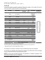
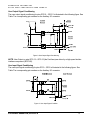
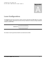
SC500 Scan Controller User Manual Part Number P0900-0150, Revision H CAMBRIDGE TECHNOLOGY INC. SC500 Scan Controller User Manual Cambridge Technology Inc. 2011-2013 Cambridge Technology Inc. is a registered trademark. P/N: P0900-0150 Rev: H Cambridge Technology, Inc. International Headquarters 125 Middlesex Turnpike Bedford, MA 01730 Tel: +1-781-266-5700 Fax: +1-781-266-5114 E-mail: [email protected] Cambridge Technology Europe Headquarters Tel: +49-89-31707-0 Fax: +49-89-31707250 E-mail: [email protected] Cambridge Technology Asia Headquarters Tel: +81 (3) 5825-8853 Fax: +81 (3) 5825-8858 E-mail: [email protected] Website: http://www.camtech.com/ Revision Notes Revision C – July 2011 Location: Tables and Figures Chapter 5 – Software Part Number P0900-0150, Revision H Update: Revised and fixed with clearer images Added i Tutorial Appendix B and C Appendix A – Universal API Reference Entire Document Added Updated to reflect DLL changes and added functions General Formatting and wording Revision D – August 2011 Location: Figure 2: Controller Layout Table 3: Laser Connector – Standard Laser Configuration Chapter 5 – Software Entire Document Update: Laser pinout fixed Pinout fixed SyncDomain Naming conventions fixed Light formatting Revision E – September 2011 Location: Chapter 2 – USB interface Chapter 2 – Laser and Auxiliary I/O connectors Chapter 5 Chapter 5 – SyncDomains Chapter 5 – Lists Chapter 5 – I/O Appendix B Appendix D Entire Document Entire Document Chapter 2 - Laser Control Chapter 3 – Theory of Operation Chapter 5 – Software Update: Added USB protection comment Added ESTOP section Renamed chapter to “The SC500 SDK” Updated SyncDomain explanation Updated List explanation Updated I/O explanation Combined tutorials in Appendix B; “Example Code Added Simple Input Detection example code Added FIFO management example code Added appendix; Laser Configuration Removed MOTF content Spacing, minor grammar and spelling Moved all laser control types to Appendix D Removed MOTF reference Updated terminology Revision F – October 2011 Location: Chapter 2 – Figure 2: Controller Layout Appendix E – ScanTest Application Appendix A – Universal API Command Reference Update: Fixed laser/DB25 pinout inconsistency New appendix added to detail this application Added new error codes Revision G – May 2012 Location: General Update: Split Theory of Operation and all software-related sections into a separate Universal API manual Revision H – January 2013 Location: General Part Number P0900-0150, Revision H Update: Updated Address ii Table of Contents IMPORTANT INFORMATION ......................................................................................................1 Safety........................................................................................................................................................................... 1 ESD Warning............................................................................................................................................................... 1 Unpacking ................................................................................................................................................................... 2 Warranty Information ................................................................................................................................................. 2 Customer Support ...................................................................................................................................................... 2 GENERAL DESCRIPTION...........................................................................................................3 System Description .................................................................................................................................................... 3 Hardware features ...................................................................................................................................................... 4 Software Features ...................................................................................................................................................... 4 Layout.......................................................................................................................................................................... 5 Inputs and Outputs .................................................................................................................................................... 6 Connector Identification ......................................................................................................................................... 6 Connector Options .................................................................................................................................................. 6 Power Input – DB9 Straight or Edge Connector .................................................................................................. 7 Single or Dual Power Supply Configurations ..................................................................................................................................................7 USB Interface ........................................................................................................................................................... 9 Laser Control – DB25 Edge or Straight Connector.............................................................................................. 9 Servo Power Output – Molex 43045-0414 connector........................................................................................... 9 Analog Servo Command - Molex 87831-0620 connector .................................................................................. 10 Servo XY2-100 Command – 14 pin IDC Header.................................................................................................. 10 Status Channel Data.............................................................................................................................................. 11 Auxiliary I/O............................................................................................................................................................ 12 ESTOP PIN.................................................................................................................................................................................................. 13 User Output Signal Conditioning......................................................................................................................... 14 User Input Signal Conditioning............................................................................................................................ 14 Jumper W4 and W5 ............................................................................................................................................... 15 Environmental Requirements ................................................................................................................................. 15 LASER CONFIGURATIONS......................................................................................................17 Part Number P0900-0150, Revision H iii List of Tables Table 1: Connector Options..........................................................................................................6 Table 2 Power Input Connector ...................................................................................................7 Table 3: Servo Power Connector..................................................................................................9 Table 4: Servo Analog Connector...............................................................................................10 Table 5: Servo XY2-100 Connector............................................................................................10 Table 6: XY2-100 Status ............................................................................................................11 Table 7: Auxiliary I/O Connector.................................................................................................12 Table 8: Connection relationships between UAPI, SC500, and various laser types. ..................18 List of Figures Figure 1: Typical Two-Axis Optical Scanning System ..................................................................3 Figure 2: Controller Layout ...........................................................................................................5 Figure 3: SC500 Connectors ........................................................................................................6 Figure 4: Servos Powered through SC500 ...................................................................................8 Figure 5: Servos Powered Directly - Digital Command.................................................................8 Figure 6: Servos Powered Directly – Analog Command...............................................................8 Figure 7: user ESTOP ................................................................................................................13 Figure 8: User Output Signal Conditioning .................................................................................14 Figure 9: User Input Signal Condition........................................................................................14 Figure 10: Guide Laser Setup.....................................................................................................19 Part Number P0900-0150, Revision H iv Part Number P0900-0150, Revision H v C A M B R I D G E T E C H N O L O G Y S C 5 0 0 S C A N C O N T R O L L E R U S E R M A N U A L Chapter 1 Important Information Safety Please read all operating instructions completely before installing and using the SC500 board. Laser Radiation: Do not stare directly into a laser beam. Follow all system laser safety requirements during installation and operation. Cambridge Technology recommends the use of a shutter to prevent unwarranted emission of laser radiation, where practical. Use of controls, adjustments, or procedures other than those specified in this manual without consulting a competent safety professional may result in component damage, and/or exposure to potential hazards. Always follow established industrial safety practices when operating equipment. ESD Warning The electronics that Cambridge Technology manufactures - including the SC500 controller - are electrostatic discharge (ESD) sensitive. Improper handling could therefore damage these electronics. Proper handling is required. The SC500 drivers and receivers for XY2-100 are rated for ESD protection to 15kV. All controller I/O pins resist ±2kV ESD per the human body model (100pF capacitor and 1500Ω resistor). Cambridge Technology has implemented procedures and precautions for handling these devices and we encourage our customers to do the same. Upon receiving your components, you should note that it is packaged in an ESD-protected container with the appropriate ESD warning labels. The equipment should remain sealed until you are located at a proper static control station. A proper static control station should include: • A soft grounded conductive tabletop or grounded conductive mat on the tabletop. • A grounded wrist strap with the appropriate (1 Mega Ohm) series resistor connected to the tabletop mat and ground. • An adequate earth ground connection such as a water pipe or AC ground. Part Number P0900-0150, Revision H 1 C A M B R I D G E T E C H N O L O G Y S C 5 0 0 S C A N C O N T R O L L E R • • • U S E R M A N U A L Conductive bags, trays, totes, racks or other containers used for storage. Properly grounded power tools. Personnel handling ESD items should wear ESD protective garments and ground straps. Note: Any equipment returned to the factory must be shipped in anti-static packaging. Unpacking Carefully unpack the contents from the box and inspect each item for damage. Check the contents of the box against the packing list to ensure reception of all parts. Contact customer service immediately if you suspect shipping damage or an incomplete shipment. Save the shipping container and packaging material in case you need to return a unit for service. Warranty Information The Customer shall examine each shipment within 10 days of receipt and inform Cambridge Technology of any shortage or damage. If no discrepancies are reported, we shall assume the shipment was delivered complete and defect free. Cambridge Technology warrantees products against defects up to 1 year from manufacture date, barring unauthorized modifications or misuse. Repaired product is warranted 90 days after the repair is made, or one year after manufacture date whichever is longer. Contact Customer Service to obtain a Return Materials Authorization (RMA) number before returning any product for repair. All orders are subject to the Cambridge Technology Terms and Conditions and Limited Warranty. Contact your local sales office for the latest version of these documents and other useful information. Customers assume all responsibility for maintaining a laser-safe working environment. OEM customers must assume all responsibility for CDRH (Center for Devices and Radiological Health) certification. Customer Support Cambridge Technology has support services to address your questions or concerns with either the product or the manual you are using. Before calling for assistance, be sure to refer to any appropriate sections in the manual that may answer your questions. Call Cambridge Technology’s Customer Service Department Monday through Friday between 8 A.M. and 5 P.M. local time (GMT – 05:00 Eastern Time (US & Canada)). Customer service personnel will be able to give you direct assistance and answers to your questions. See the Copyright page for contact information. Part Number P0900-0150, Revision H 2 C A M B R I D G E T E C H N O L O G Y S C 5 0 0 S C A N C O N T R O L L E R U S E R M A N U A L Chapter 2 General Description System Description Cambridge Technology continues the advancement of scan and laser control products with the SC500 scan controller. The SC500 scan controller: • Connects to a host PC through a USB port to provide digital or analog commands to scanner sets and scan heads. • Enables easy system integration with its laser control (interfaces including CO2 tickle pulse and first pulse suppression) and opto-isolation of IO ports. • Comes with a fully functional software library. In addition, Cambridge Technology offers the ScanMaster API as well as ScanMaster Designer* *For more information see www.camtech.com Figure 1: Typical Two-Axis Optical Scanning System (including galvos, servos, and control electronics) The SC500 controller and software package is intended to provide essential laser marker functionality, with a feature set adequate for most marking applications. The SC500 scan controller and software can be used for welding, laser guidance and many other applications. The SC500 scan controller is connected to a host PC via a USB connection. This is often the same PC used as the human machine interface (HMI) in a production application. Part Number P0900-0150, Revision H 3 C A M B R I D G E T E C H N O L O G Y S C 5 0 0 S C A N C O N T R O L L E R U S E R M A N U A L The SC500 has mounting holes for securely fastening it to a chassis assembly and can be placed up to 3 meters from the PC. The SC500 controller is designed for ease of embedding within a scan head or the PC itself. Hardware features • USB 2.0 Interface • 2 general purpose optically isolated outputs for interface to automation systems. • 2 general purpose optically isolated inputs plus one high speed Start Mark input for interface to automation systems. • 0-5V analog isolated Laser power control Output • Direct cable-level interfacing with the IPG YLP type-B interface. • Power input from a male DB9 power connector. • Three 4-conductor Molex 3mm connectors for power connection to servos. • Three 6-conductor Molex 2mm signal connectors for analog servo control. (3-axis analog command signals using 16 Bit D/A Converters to convert digital position command to +/-10V differential analog voltage). • Generates 3-axis XY2-100 output as defined in the industry standard digital XY2-100 communication specification and accepts return of status information over the interface. • Monitors configurable servo ready signal from servos and updates via XY2-100 data stream. • Connectors can be populated on either the top or bottom of the board if necessary to accommodate different packaging designs. Software Features • Command Data Stream • Status Data Stream • Optional Programmable laser control and I/O connectors pinout • Compatibility with Windows XP, Vista and 7. Part Number P0900-0150, Revision H 4 C A M B R I D G E T E C H N O L O G Y S C 5 0 0 S C A N C O N T R O L L E R U S E R M A N U A L Layout The controller layout is shown below. Dimensions are shown in inches. The outer board dimensions are 3.9” (9.91 cm) by 2.9” (7.36 cm). The DB9 and DB25 connectors are in the same relative locations as most XY2-100 receiver boards. Figure 2: Controller Layout NOTE: There are two unlisted connectors, one located below the XY2-100 port, and another located under the USB 2.0 port. These connectors are used to configure the board during manufacture ONLY and are not for customer use. Part Number P0900-0150, Revision H 5 C A M B R I D G E T E C H N O L O G Y S C 5 0 0 S C A N C O N T R O L L E R U S E R M A N U A L Inputs and Outputs Connector Identification Figure 3: SC500 Connectors Connector Options The SC500 is provided with a standard connector configuration as depicted in the table below. The additional connector options in the table are available for qualified customers. Connector Default Option Power & Laser (D-sub) Straight (vertical) Edge (right-angle) Servo outputs Analog circuitry USB Top of Board (same as D-sub) Included B-style Socket Bottom of Board Omitted 5-Pin Header Table 1: Connector Options Part Number P0900-0150, Revision H 6 C A M B R I D G E T E C H N O L O G Y S C 5 0 0 S C A N C O N T R O L L E R U S E R M A N U A L Power Input – DB9 Straight or Edge Connector The acceptable voltage for this input connection is ±15V to ±28V DC. The board will require no more than 200mA of current. Make sure not to exceed the power requirement of the scanner set / scan head connected to the SC500 controller! Please refer to the scanner set or scan head hardware’s documentation that you are connecting to the SC500. Pin Function 1 - Supply 2 - Supply 3 Power Return (tied to Sig. Ground) 4 + Supply 5 + Supply 6 - Supply 7 Power Return (tied to Sig. Ground) 8 Power Return (tied to Sig. Ground) 9 + Supply DB9 Mating Connector Pinout Table 2 Power Input Connector SINGLE OR DUAL P OW ER S UPPL Y CONFIGURATIONS The power input can be configured either as a single or a dual power supply depending on the system configuration, as seen in the following examples. If the servos are powered through the SC500, a single power supply is required, as shown in the following diagram. Part Number P0900-0150, Revision H 7 C A M B R I D G E T E C H N O L O G Y S C 5 0 0 S C A N C O N T R O L L E R U S E R M A N U A L Figure 4: Servos Powered through SC500 If the servos are powered directly by a separate power supply and the SC500 is generating a digital (XY2-100) command, a dual power supply is used, as shown in the following diagram. Figure 5: Servos Powered Directly - Digital Command If the servos are powered directly by a separate power supply and the SC500 is generating an analog command, a dual power supply is used, as shown in the following diagram. Servo PSU Servo Specific Voltage Servo Head Servo Power Servo SC500 PSU + 15V - SC500 Power Laser SC500 PC Analog USB 2.0 Connection Figure 6: Servos Powered Directly – Analog Command Part Number P0900-0150, Revision H 8 C A M B R I D G E T E C H N O L O G Y S C 5 0 0 S C A N C O N T R O L L E R U S E R M A N U A L USB Interface A USB 2.0 connection is used to stream data to and from the PC through a right-angle USB edge connector on the side edge of the board. For implementation inside a scan head, a 5-pin 0.1” inline header is available for cabling to a bulkhead USB connector, such as the Bulgin P/N PX0443. The controller buffers the data on both sides of the USB connection, to prevent any disruptions in the command data. The board does not draw any power from the USB connector. To prevent a ground loop from damaging the PC, we suggest using a USB hub for the SC500 connection. Pin Function 1 VCC 2 3 4 5 DD+ GND Shield J12 USB Board Connector Pinout Laser Control – DB25 Edge or Straight Connector The SC500 Utilizes a DB25 connector for laser control. The pinouts can be found in Appendix A – Laser Configurations. Appendix A also shows the pin functions for lasers commonly used with the SC500. Servo Power Output – Molex 43045-0414 connector Mate: Molex 43025-0400 (contacts 43030-0006 for 26-30AWG). Each of these 3 connectors sends power and ground to one servo driver. The pinout matches the CTI ASD and 677 Servo board power connectors to simplify cabling. Pin 1 2 3 4 Function Signal Ground Chassis Ground -VDRV +VDRV Molex Mating Connector Pinout Table 3: Servo Power Connector Part Number P0900-0150, Revision H 9 C A M B R I D G E T E C H N O L O G Y S C 5 0 0 S C A N C O N T R O L L E R U S E R M A N U A L Analog Servo Command - Molex 87831-0620 connector Mate: Molex 51110-0660 (contacts 50394-8200 for 26-30AWG). These connectors are used to send the ±10V differential analog command voltage to the X, Y, and Z servo drivers. They also return digital servo ready signal to the board, as well as a probe signal feedback. The board provides a pull-up for the active low servo ready signal if available. Pin Function 1 -Command Out 2 3 4 5 +Command Out ~Ready* Chassis Ground Probe In 6 Signal Ground Molex Mating Connector Pinout Table 4: Servo Analog Connector *Ready signal input from the servo. Servo Ready can be connected to the signal ground if a signal is not required from the servo. Servo XY2-100 Command – 14 pin IDC Header This interface is used to generate 3-axis digital position commands and to report servo status. Pin Name XY2-100 Serial Link 1 2 3 4 5 CLKCLK+ SYNCSYNC+ XDATA- Clock, 1.875MHz nominal 6 7 8 9 10 11 XDATA+ YDATAYDATA+ ZDATAZDATA+ STAT- 12 13 14 STAT+ NC NC XY2-100 Board Pinout Indicates start of 20bit data word 20-bit X-axis data send 20-bit Y-axis data send 20-bit Z-axis data send 20-bit status return Table 5: Servo XY2-100 Connector All XY2-100 output differential pairs are driven to EIA-422 standard. STAT differential inputs are terminated by 150Ω plus 680Ω bias (input + 680Ω to 3.3V, input - Part Number P0900-0150, Revision H 10 C A M B R I D G E T E C H N O L O G Y S C 5 0 0 S C A N C O N T R O L L E R U S E R M A N U A L Status Channel Data 2-axis status data is generated from Status Channels per the following table: Bit XY2-100 definition Value C2 0 0 C1 1 1 C0 1 1 S15 Power Status XReady & YReady S14 Temperature Status 1 S13 In-field 1 S12 1 1 S11 1 1 S10 1 1 S9 x 0 S8 x 1 S7 Power Status XReady & YReady S6 Temperature Status 1 S5 In-field 1 S4 1 1 S3 1 1 S2 1 1 S1 x 0 S0 x 1 Par x (no parity) even parity Table 6: XY2-100 Status Part Number P0900-0150, Revision H 11 C A M B R I D G E T E C H N O L O G Y S C 5 0 0 S C A N C O N T R O L L E R U S E R M A N U A L Auxiliary I/O A 20-pin IDC header is provided for auxiliary I/O. Many of the signals on the Auxiliary I/O pins also occur on the Laser Connector as seen in the following table. Pin Pin Name Special Use Laser Connector (See Table 3) Description Auxiliary I/O Board Pinout Data can’t be delivered to SC500 fast enough SC500 in idle state 1 GPO0 fifo_underrun 2 GPO1 not_busy 3 4 GPO2 GPO3 Laser Master Oscillator Guide Laser Pin 18 Pin 22 5 GPO4 Free for user Pin 1 6 GPO5 Free for user Pin 2 7 8 9 GPO6 GPO7 GPI0 Laser Data 2 Laser Data 3 (Encoder In) Pin 3 Pin 4 10 GPI1 (MOTF Event) 11 12 13 GPI2 GPI3 GPI4 Laser Status 0 Laser Status 1 Free for user 14 15 GPI5 GPO15 LSR_PWR_PWM_OUT 16 ESTOP 17 18 +5.0_ISO GND_ISO 19 LSR_PWR_ANALO G 20 GND_ISO UserOut 3 UserOut 4 User Out Data User Out Data Start Mark Start marking process UserIn3 User In Data UserIn4 User In Data PWM signal** Pin is only for laser use Pin 21 Pin 16 Free for user Configured to 5V pulldown SMD Pin Name* Pin 23 0 – 5 V signal 300 KHz BW** Table 7: Auxiliary I/O Connector *ScanMaster Designer software ScanScript scripting language. For more information about ScanMaster Designer software and ScanScript see www.camtech.com ** Signal proportional to the 8-bit laser digital power command. The Auxiliary I/O Connection is intended to allow the SC500 board system level integration. The I/O Ports are accessed via the physical pins described in the table above and are managed using the Universal API Software Development Kit provided. NOTE: The pinout and accessibility described is only applicable to a standard configuration of the board and can change as per your configuration. Part Number P0900-0150, Revision H 12 C A M B R I D G E T E C H N O L O G Y S C 5 0 0 S C A N C O N T R O L L E R U S E R M A N U A L ESTOP PIN The ESTOP pin listed in the Auxiliary I/O connector (pin 16) is routed directly to the ESTOP pin listed in the Laser Control connector (pin 23). This pin is only for the IPG laser, but can be used for other laser configurations (see Appendix D – Laser Configurations). The two pins (Auxiliary I/O pin 16 and Laser Control connector pin 25) are tied to a resistor which pulls both to a logic high state (5V), and does nothing else. Figure 7: user ESTOP The intended use of these pins is to have the Laser Control connector’s ESTOP pin be plugged into the IPG laser, and the Auxiliary I/O connector’s ESTOP pin be connected to some external switch/failsafe solution. The switch should pull the ESTOP pin state to a logic low by grounding it, when this happens the Laser Control connector ESTOP pin will also be grounded and the laser will be forced to turn off via its own failsafe mechanism. Grounding the ESTOP pin will have no effect on the SC500, and is NOT a hardware failsafe solution for the SC500. If you are not using an IPG laser, you are still free to utilize the functionality offered from these pins to implement your own failsafe solution or use it for some other implementation of your choosing. Part Number P0900-0150, Revision H 13 C A M B R I D G E T E C H N O L O G Y S C 5 0 0 S C A N C O N T R O L L E R U S E R M A N U A L User Output Signal Conditioning The user output signal conditioning for pins GPO 0 – GPO11 is illustrated in the following figure. See Table 7 for corresponding pin numbers on the Auxiliary I/O connector. Figure 8: User Output Signal Conditioning NOTE: User Output on pins GPO 12 – GPO 15 (the Fast lines) are driven by a high speed isolator interface component (ISO7240). User Input Signal Conditioning The user input signal conditioning for pins GPI 0 – GPI 5 is illustrated in the following figure. See Table 7 for corresponding pin numbers on the Auxiliary I/O connector. Figure 9: User Input Signal Condition Part Number P0900-0150, Revision H 14 C A M B R I D G E T E C H N O L O G Y S C 5 0 0 S C A N C O N T R O L L E R U S E R M A N U A L Jumper W4 and W5 Jumpers W4 and W5 give the option to isolate the outputs and voltage from the SC500 and allow them to be user-supplied. Leaving the jumpers in place will keep the outputs and voltage supplied by the SC500. Removing the jumpers will allow the outputs to be isolated and user-specified. Jumper W4 – jumps Voltage Jumper W5 – jumps Ground It is recommended to either leave both jumpers in place or remove both, leaving only jumper W4 in may potentially cause damage to the board. Environmental Requirements • Operating temperature: +10 to +60ºC • Storage temperature: -20 to +100ºC • Humidity: 10% to 85% RH non-condensing • Shock: 500G (0.5ms half sine-wave) • Vibration: 10G (55Hz to 2kHz) operating Part Number P0900-0150, Revision H 15 C A M B R I D G E T E C H N O L O G Y S C 5 0 0 S C A N C O N T R O L L E R U S E R Part Number P0900-0150, Revision H M A N U A L 16 C A M B R I D G E T E C H N O L O G Y S C 5 0 0 S C A N C O N T R O L L E R U S E R M A N U A L Appendix A Laser Configurations This appendix shows the pin functions for lasers commonly used with the SC500. Below is an image of the DB25 straight or edge board connector and its pin numbers for reference (looking towards the connector on the SC500): DB25 Pinout: Also shown is how the guide laser should be connected and controlled. Part Number P0900-0150, Revision H 17 C A M B R I D G E T E C H N O L O G Y S C 5 0 0 S C A N C O N T R O L L E R Pin 1 2 3-8 9 10-15 16 17 U S E R M A N U A L Pin Definitions for Common Laser Types see Note 1 IPG YLP Type “B” CO2 Lasers with FPS Laser Power, Bit 0, LSB Laser Power, Bit 1 Laser Power, Bits 2-7 Laser Power Latch Control Ground Laser Alarms Status, Line 1 Guide Laser DC Power Ground Guide Laser DC Power 18 19 Master Oscillator On/Off Power Amplifier On/Off 20 Pulse Synchronization Laser Modulation 21 22 23 24 25 Laser Alarms Status, Line 2 Guide Laser On/Off Emergency Stop Ground Laser Power Output Monitor Guide Laser On/Off Emergency Stop Ground Laser Modulation Ground Guide Laser DC Power Laser Modulation Gate First Pulse Suppression Guide Laser On/Off Emergency Stop Ground Access through the Universal API UAPI Designations UAPI Commands DIGITAL_OUTPUTS (Bit 4) see Note 2 DIGITAL_OUTPUTS (Bit 5) see Note 2 n/a UA_set_laser_power UAL_set_laser_power DIGITAL_LASER_POWER UA_write_io_port UAL_write_io_port n/a see Note 3 n/a n/a DIGITAL_INPUTS (Bit 2) UA_read_digital_port n/a n/a DIGITAL_OUTPUTS (Bit 12) n/a see Note 2 see Note 3 n/a see Note 3 DIGITAL_INPUTS (Bit 3) DIGITAL_OUTPUTS (Bit 13) n/a n/a n/a UA_read_digital_port see Note 2 see Note 4 n/a n/a Level TTL/CMOS TTL/CMOS TTL/CMOS TTL/CMOS Ground TTL/CMOS 5±0.25VDC TTL/CMOS TTL/CMOS TTL/CMOS TTL/CMOS TTL/CMOS TTL/CMOS Ground NC Table 8: Connection relationships between UAPI, SC500, and various laser types. Notes: 1. These pin definitions are for differing factory configurations. Entries for the IPG laser and the CO2 laser refer to the standard SC500 configuration. Lasers needing FPS (First Pulse Suppression) require a special factory configuration. 2. All commands for writing to digital ports can be used. These are as follows: UA_write_io_port, UA_assert_io_port, UA_clear_io_port, UAL_write_io_port, UAL_assert_io_port, UAL_clear_io_port. 3. These pins are not directly controllable via UAPI commands, but are driven by the SC500 when necessary as the result of issued UAPI commands. 4. Pin 23 is routed to pin 16 on the SC500’s auxiliary IO header connector, and is pulled up to 5V. The UAPI has no control over this pin. Part Number P0900-0150, Revision H 18 C A M B R I D G E T E C H N O L O G Y S C 5 0 0 S C A N C O N T R O L L E R U S E R M A N U A L Figure 10: Guide Laser Setup Part Number P0900-0150, Revision H 19 C A M B R I D G E T E C H N O L O G Y S C 5 0 0 S C A N C O N T R O L L E R U S E R M A N U A L End of Document Part Number P0900-0150, Revision H 20